WO2018159782A1 - タイヤ - Google Patents
タイヤ Download PDFInfo
- Publication number
- WO2018159782A1 WO2018159782A1 PCT/JP2018/007894 JP2018007894W WO2018159782A1 WO 2018159782 A1 WO2018159782 A1 WO 2018159782A1 JP 2018007894 W JP2018007894 W JP 2018007894W WO 2018159782 A1 WO2018159782 A1 WO 2018159782A1
- Authority
- WO
- WIPO (PCT)
- Prior art keywords
- groove
- width direction
- tire
- width
- direction groove
- Prior art date
- Legal status (The legal status is an assumption and is not a legal conclusion. Google has not performed a legal analysis and makes no representation as to the accuracy of the status listed.)
- Ceased
Links
Images



Classifications
-
- B—PERFORMING OPERATIONS; TRANSPORTING
- B60—VEHICLES IN GENERAL
- B60C—VEHICLE TYRES; TYRE INFLATION; TYRE CHANGING; CONNECTING VALVES TO INFLATABLE ELASTIC BODIES IN GENERAL; DEVICES OR ARRANGEMENTS RELATED TO TYRES
- B60C11/00—Tyre tread bands; Tread patterns; Anti-skid inserts
- B60C11/03—Tread patterns
- B60C11/13—Tread patterns characterised by the groove cross-section, e.g. for buttressing or preventing stone-trapping
-
- B—PERFORMING OPERATIONS; TRANSPORTING
- B60—VEHICLES IN GENERAL
- B60C—VEHICLE TYRES; TYRE INFLATION; TYRE CHANGING; CONNECTING VALVES TO INFLATABLE ELASTIC BODIES IN GENERAL; DEVICES OR ARRANGEMENTS RELATED TO TYRES
- B60C11/00—Tyre tread bands; Tread patterns; Anti-skid inserts
- B60C11/01—Shape of the shoulders between tread and sidewall, e.g. rounded, stepped or cantilevered
-
- B—PERFORMING OPERATIONS; TRANSPORTING
- B60—VEHICLES IN GENERAL
- B60C—VEHICLE TYRES; TYRE INFLATION; TYRE CHANGING; CONNECTING VALVES TO INFLATABLE ELASTIC BODIES IN GENERAL; DEVICES OR ARRANGEMENTS RELATED TO TYRES
- B60C11/00—Tyre tread bands; Tread patterns; Anti-skid inserts
- B60C11/03—Tread patterns
-
- B—PERFORMING OPERATIONS; TRANSPORTING
- B60—VEHICLES IN GENERAL
- B60C—VEHICLE TYRES; TYRE INFLATION; TYRE CHANGING; CONNECTING VALVES TO INFLATABLE ELASTIC BODIES IN GENERAL; DEVICES OR ARRANGEMENTS RELATED TO TYRES
- B60C11/00—Tyre tread bands; Tread patterns; Anti-skid inserts
- B60C11/03—Tread patterns
- B60C11/0306—Patterns comprising block rows or discontinuous ribs
-
- B—PERFORMING OPERATIONS; TRANSPORTING
- B60—VEHICLES IN GENERAL
- B60C—VEHICLE TYRES; TYRE INFLATION; TYRE CHANGING; CONNECTING VALVES TO INFLATABLE ELASTIC BODIES IN GENERAL; DEVICES OR ARRANGEMENTS RELATED TO TYRES
- B60C11/00—Tyre tread bands; Tread patterns; Anti-skid inserts
- B60C11/03—Tread patterns
- B60C2011/0337—Tread patterns characterised by particular design features of the pattern
- B60C2011/0339—Grooves
- B60C2011/0341—Circumferential grooves
- B60C2011/0353—Circumferential grooves characterised by width
-
- B—PERFORMING OPERATIONS; TRANSPORTING
- B60—VEHICLES IN GENERAL
- B60C—VEHICLE TYRES; TYRE INFLATION; TYRE CHANGING; CONNECTING VALVES TO INFLATABLE ELASTIC BODIES IN GENERAL; DEVICES OR ARRANGEMENTS RELATED TO TYRES
- B60C11/00—Tyre tread bands; Tread patterns; Anti-skid inserts
- B60C11/03—Tread patterns
- B60C2011/0337—Tread patterns characterised by particular design features of the pattern
- B60C2011/0339—Grooves
- B60C2011/0358—Lateral grooves, i.e. having an angle of 45 to 90 degees to the equatorial plane
- B60C2011/0365—Lateral grooves, i.e. having an angle of 45 to 90 degees to the equatorial plane characterised by width
-
- B—PERFORMING OPERATIONS; TRANSPORTING
- B60—VEHICLES IN GENERAL
- B60C—VEHICLE TYRES; TYRE INFLATION; TYRE CHANGING; CONNECTING VALVES TO INFLATABLE ELASTIC BODIES IN GENERAL; DEVICES OR ARRANGEMENTS RELATED TO TYRES
- B60C11/00—Tyre tread bands; Tread patterns; Anti-skid inserts
- B60C11/03—Tread patterns
- B60C2011/0337—Tread patterns characterised by particular design features of the pattern
- B60C2011/0339—Grooves
- B60C2011/0358—Lateral grooves, i.e. having an angle of 45 to 90 degees to the equatorial plane
- B60C2011/0367—Lateral grooves, i.e. having an angle of 45 to 90 degees to the equatorial plane characterised by depth
-
- B—PERFORMING OPERATIONS; TRANSPORTING
- B60—VEHICLES IN GENERAL
- B60C—VEHICLE TYRES; TYRE INFLATION; TYRE CHANGING; CONNECTING VALVES TO INFLATABLE ELASTIC BODIES IN GENERAL; DEVICES OR ARRANGEMENTS RELATED TO TYRES
- B60C11/00—Tyre tread bands; Tread patterns; Anti-skid inserts
- B60C11/03—Tread patterns
- B60C2011/0337—Tread patterns characterised by particular design features of the pattern
- B60C2011/0339—Grooves
- B60C2011/0358—Lateral grooves, i.e. having an angle of 45 to 90 degees to the equatorial plane
- B60C2011/0367—Lateral grooves, i.e. having an angle of 45 to 90 degees to the equatorial plane characterised by depth
- B60C2011/0369—Lateral grooves, i.e. having an angle of 45 to 90 degees to the equatorial plane characterised by depth with varying depth of the groove
-
- B—PERFORMING OPERATIONS; TRANSPORTING
- B60—VEHICLES IN GENERAL
- B60C—VEHICLE TYRES; TYRE INFLATION; TYRE CHANGING; CONNECTING VALVES TO INFLATABLE ELASTIC BODIES IN GENERAL; DEVICES OR ARRANGEMENTS RELATED TO TYRES
- B60C11/00—Tyre tread bands; Tread patterns; Anti-skid inserts
- B60C11/03—Tread patterns
- B60C2011/0337—Tread patterns characterised by particular design features of the pattern
- B60C2011/0339—Grooves
- B60C2011/0381—Blind or isolated grooves
-
- B—PERFORMING OPERATIONS; TRANSPORTING
- B60—VEHICLES IN GENERAL
- B60C—VEHICLE TYRES; TYRE INFLATION; TYRE CHANGING; CONNECTING VALVES TO INFLATABLE ELASTIC BODIES IN GENERAL; DEVICES OR ARRANGEMENTS RELATED TO TYRES
- B60C11/00—Tyre tread bands; Tread patterns; Anti-skid inserts
- B60C11/03—Tread patterns
- B60C11/13—Tread patterns characterised by the groove cross-section, e.g. for buttressing or preventing stone-trapping
- B60C11/1307—Tread patterns characterised by the groove cross-section, e.g. for buttressing or preventing stone-trapping with special features of the groove walls
- B60C2011/1338—Tread patterns characterised by the groove cross-section, e.g. for buttressing or preventing stone-trapping with special features of the groove walls comprising protrusions
Definitions
- the present invention relates to a tire.
- the air column resonance sound is noise generated by resonance of air in the pipe surrounded by a circumferential groove extending continuously in the circumferential direction of the tread surface and a road surface, and is about 800 to 1200 Hz in a general passenger car. Often observed. Such air column resonance sound has a high peak level and a wide frequency band, and therefore occupies most of the noise generated from the tire.
- a side branch type resonator having a longitudinal groove and a lateral groove is provided in a rib-like land portion partitioned by a plurality of circumferential grooves.
- Patent Document 1 a side branch type resonator having a longitudinal groove and a lateral groove is provided in a rib-like land portion partitioned by a plurality of circumferential grooves.
- Patent Document 2 an air chamber that opens on the surface of the land portion at a position spaced apart from the circumferential groove, and one or more constricted necks that communicate the air chamber with the circumferential groove.
- a Helmholtz type resonator Patent Document 2
- an object of the present invention is to provide a tire that can reduce the air column resonance noise, maintain the degree of freedom of tread design, and suppress uneven wear in the tread.
- the tire of the present invention is a tire having at least one circumferential groove extending continuously in the tire circumferential direction on the tread surface, and a shoulder land portion defined by the circumferential groove and the tread ground contact end.
- the shoulder land portion has a first width direction groove extending in the tire width direction and communicating the circumferential groove and the tread grounding end, and the first width direction groove is formed in the first width direction groove.
- the second width direction groove communicates with the first width direction groove, and each of the circumferential groove, the first width direction groove, and the second width direction groove has a relational expression “circumference The groove width of the direction groove> the groove width of the first width direction groove> the groove width of the second width direction groove ”is satisfied. According to the tire of the present invention having such a configuration, the degree of freedom in designing the tread can be maintained and uneven wear in the tread can be suppressed while air column resonance noise is reduced.
- the “tread surface” refers to a road surface when a tire that is assembled to a rim and filled with a predetermined internal pressure is rolled with a maximum load applied.
- the outer peripheral surface of the entire circumference of the tire is meant, and the “tread grounding end” means the end in the tire width direction of the tread surface.
- the “reference state” refers to a state in which the tire is assembled to the rim, filled with a predetermined internal pressure, and no load is applied, and “when the tire is in contact with the ground” means that the tire is assembled to the rim, It refers to the time when the vehicle is stopped on a flat road surface with a predetermined internal pressure filled and the maximum load applied.
- rim is an industrial standard valid for the region where tires are produced and used.
- JATMA Joint Automobile Tire Association
- JATMA YEAR BOOK in Europe ETRTO (The European Tire and Rim Technical STANDARDS MANUAL (Organization), standard rims in applicable sizes described in the YEAR BOOK of the TRA (The Tire and Rim Association, Inc.) in the U.S.
- ETRTO European Tire and Rim Technical STANDARDS MANUAL (Organization)
- standard rims in applicable sizes described in the YEAR BOOK of the TRA The Tire and Rim Association, Inc.
- the above “rim” includes not only the current size but also the size that can be included in the industry standard in the future.
- the size listed as “FUTURE DEVELOPMENTS” in STANDARDS MANUAL 2013 edition of ETRTO can be cited.
- the size is not listed in the above industrial standards, It refers to the rim of the width.
- the “predetermined internal pressure” refers to the air pressure (maximum air pressure) corresponding to the maximum load capacity of a single wheel in the applicable size and ply rating, as described in the above JATMA YEAR BOOK, etc.
- the “predetermined internal pressure” refers to the air pressure (maximum air pressure) corresponding to the maximum load capacity defined for each vehicle on which the tire is mounted.
- the “maximum load load” refers to a load corresponding to the maximum load capacity.
- the air can be replaced with an inert gas such as nitrogen gas or the like.
- the groove width of the circumferential groove refers to a length in a direction perpendicular to the extending direction of the circumferential groove, measured in a reference state.
- the groove width of the first width direction groove and “the groove width of the second width direction groove” are the extending direction of the first width direction groove having the second width direction groove measured in the reference state.
- the length in the direction orthogonal to In any of the above grooves when the groove width changes along the depth direction of the groove, the groove width (hereinafter referred to as the maximum width) is specified unless otherwise specified such as the measurement position in the depth direction. In this embodiment, it is indicated by W1, W2, and W3).
- the dimensions and the like of each element such as a groove are measured in a reference state (the dimensions and the like of each element on the tread surface are in a development view of the tread surface in the reference state).
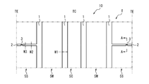
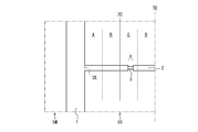
- FIG. 1 is a development view schematically showing a tread surface of a tire according to an embodiment of the present invention.
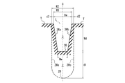
- FIG. 2 is a cross-sectional view of a second width direction groove taken along the line AA in FIG. 1. It is sectional drawing of the 2nd width direction groove
- FIG. 2 is a partially enlarged development view of a shoulder land portion of the tire shown in FIG. 1.
- FIG. 1 is a development view schematically showing a tread surface T of a tire 10 according to an embodiment of the present invention.
- the tire 10 continuously extends in the tire circumferential direction on the tread surface T (in the illustrated example, continuously in the tire circumferential direction along the tire circumferential direction, that is, at an angle of 0 ° with respect to the tire circumferential direction.
- the circumferential groove 1 in the present embodiment is a linear groove extending continuously in the tire circumferential direction along the tire circumferential direction.
- the circumferential groove 1 is the tire circumferential direction (tire It can also be a zigzag or wavy groove that is inclined with respect to the equator plane TC) and extends continuously in the tire circumferential direction.
- the number of circumferential grooves 1 is four. In the case of a plurality, it may be 2, 3, or 5 or more.
- the tire 10 of the present embodiment is partitioned on the tread tread T by the at least one circumferential groove 1 continuously extending in the tire circumferential direction, the circumferential groove 1 and the tread grounding end TE. It has a shoulder land portion 5S.
- the tire of the present embodiment is a pneumatic radial tire for passenger cars, but the present invention can also be applied to other types of tires that are required to reduce air column resonance noise.
- the shoulder land portion 5S extends in the tire width direction and communicates with the circumferential groove 1 and the tread grounding end TE.
- a plurality of shoulder land portions 5S are arranged apart from each other in the tire circumferential direction (in the illustrated example, 1), and a plurality of block-shaped land portions are formed in the tire circumferential direction by the first width direction groove 2.
- the first width direction groove 2 has a second width direction groove 3 communicating with the first width direction groove 2 in the first width direction groove 2.
- the second width direction groove 3 is formed at both ends in the extending direction of the second width direction groove 3 so that the first width direction groove 2 can communicate with the circumferential groove 1 and the tread grounding end TE.
- the groove width W2 of the first width direction groove 2 in the present embodiment is smaller than the groove width W1 of the circumferential direction groove 1. More specifically, the first width direction groove 2 is a narrow groove having a groove width of, for example, about 2 mm, and the groove width is the entire area in the tire width direction except for the region where the second width direction groove 3 is disposed. Over a period of time.
- the first width direction groove 2 preferably has a smaller cross-sectional area and / or a smaller groove depth than the circumferential direction groove 1.
- the first width direction groove 2 extends along the tire width direction (that is, at an angle of 0 ° with respect to the tire width direction), but the first width direction groove 2 is the tire width direction. For example, it may extend at an angle of 45 ° or less as long as it has a tire width direction component.
- FIG. 2 is a cross-sectional view taken along line AA shown in FIG. 1, and is perpendicular to the extending direction of the first width direction groove 2 of the second width direction groove 3 provided in the first width direction groove 2.
- the cross section by a surface is shown.
- the shapes of the groove walls 2Wa and 2Wb and the groove bottom 2B of the first width direction groove 2 are indicated by broken lines.
- the second width direction groove 3 is shallower than the first width direction groove 2, and the groove width W3 is narrowed.
- the groove walls (both groove walls defining the second width direction groove 3) 3Wa, 3Wb of the second width direction groove 3 have a first width as they go to the depth direction groove bottom 3B side of the second width direction groove 3. Inclined and extended in a direction approaching the opening center line C of the directional groove 2, and the groove bottom 3 ⁇ / b> B of the second width direction groove 3 is connected to the inner ends in the tire radial direction. Therefore, the second width direction groove 3 in the present embodiment has an inverted trapezoidal cross section.
- each groove width of the circumferential groove 1, the first width direction groove 2, and the second width direction groove 3 is expressed by a relational expression “groove width W1 of the circumferential groove 1> first width.
- the groove width W2 of the direction groove 2> the groove width W3 of the second width direction groove 3 ” must be satisfied.
- the circumferential groove 1 and the first width direction are generated. Since the groove widths W 1, W 2, W 3 between the groove 2 and the second width direction groove 3 satisfy the above relationship, the resonance noise can be reduced via the second width direction groove 3.
- the resonance noise is reduced by being discharged to the outside or being absorbed by the groove walls 3Wa, 3Wb, the groove bottom 3B, and the like of the second width direction groove 3.
- air column resonance can be reduced by utilizing the sound wave attenuation effect due to the viscosity of the air in the second width direction groove 3, particularly the inlet and outlet thereof.
- the tire according to the present invention it is not necessary to provide a groove or a concave portion having a large or complicated shape on the tread surface unlike the conventional branch type or Helmholtz type resonator, and the tire is narrow in the second width direction groove 2. Since it is only necessary to provide the second widthwise groove 3 of the width, the degree of freedom in tread design can be maintained, and furthermore, the land portion rigidity of the tread is unlikely to be uneven, thereby suppressing uneven wear on the tread surface. can do. That is, in the tire of the present invention, the air column resonance sound can be attenuated in the first width direction groove 2 without disposing a specific resonator on the tread surface, so that the freedom of design of the tread is not hindered. In addition, air column resonance can be reduced while maintaining the land rigidity of the tread uniform. However, other resonators may be provided.
- the ratio (W2 / W1) between the groove width W2 of the first widthwise groove 2 and the groove width W1 of the circumferential groove 1 is 0.1 or more and 0.5 or less. preferable. If it is 0.1 or more, a sufficient amount of air can be sent into the first width direction groove 2, so that the air column resonance can be further reduced. Further, if it is 0.5 or less, the first width direction groove 2 can sufficiently throttle the air flowing from the circumferential direction groove 1, and relatively high speed air can be sent to the second width direction groove 3, The air column resonance can be further reduced, the degree of freedom in designing the tread can be more sufficiently secured, and uneven wear in the tread can be further suppressed. Moreover, if it is 0.5 or less, pattern noise can be reduced. The ratio is more preferably 0.2 or more and 0.4 or less for the same reason.
- the ratio (W3 / W2) between the groove width W3 of the second width direction groove 3 and the groove width W2 of the first width direction groove 2 is preferably 0.1 or more and 0.8 or less. If it is 0.1 or more, a sufficient amount of air can be fed into the second width direction groove 3, so that air column resonance can be further reduced. Moreover, if it is 0.8 or less, the air flowing from the first width direction groove 2 can be sufficiently throttled by the second width direction groove 3, so that air column resonance can be further reduced.
- the ratio is more preferably 0.2 or more and 0.6 or less for the same reason.
- channel when a groove width changes along the extension direction of a groove
- the groove width of the second width direction groove when the groove width of the second width direction groove changes along the extending direction of the second width direction groove, the second width direction groove and the first width direction groove communicated with the second width direction groove.
- the groove width of the second width direction groove is the groove width of the second width direction groove at the boundary position, and the groove width of the first width direction groove changes along the extending direction of the first width direction groove.
- the maximum groove width is defined as the groove width of the first width direction groove.
- the groove width of the first width direction groove and the groove width of the second width direction groove may change continuously and smoothly at the boundary position of both grooves, but from the viewpoint of enhancing the effect of reducing air column resonance noise. It is preferable that it is not continuously and smoothly changing at the boundary position of both grooves.
- the groove width of the first width direction groove and the groove width of the second width direction groove are intermittent at the boundary position between both grooves as in this embodiment from the viewpoint of further enhancing the effect of reducing air column resonance noise. It is particularly preferable that the groove width of the first width direction groove is different from the groove width of the second width direction groove at the boundary position (boundary surface).
- the distance d1 between the groove bottom 3B of the second width direction groove 3 and the groove bottom 2B of the first width direction groove 2 is preferably 1.0 mm or more. This is because the air flowing in the vicinity of the groove bottom 2B of the first width direction groove 2 is low speed due to the effect of friction with the groove bottom 2B, but the air flowing in a region separated by 1 mm or more from the groove bottom 2B This is because the sufficiently high speed air layer passes through the second width direction groove 3 to increase the damping effect due to the viscosity and further reduce the air column resonance sound.
- the distance d2 between the groove walls 3Wa and 3Wb of the second width direction groove 3 and the groove walls 2Wa and 2Wb of the first width direction groove 2 is preferably 0.25 mm or more. This is because the air flowing in the vicinity of the groove walls 2Wa and 2Wb of the first widthwise groove 2 is low speed due to the influence of friction with the groove walls 2Wa and 2Wb, but 0.25 mm from the groove walls 2Wa and 2Wb. The air flowing in the above-separated region is relatively high speed, and this relatively high speed air passes through the second width direction groove 3 to increase the damping effect due to viscosity and further reduce air column resonance noise. is there.
- the distance between the groove bottom of the second width direction groove and the groove bottom of the first width direction groove and “the distance between the groove wall of the second width direction groove and the groove wall of the first width direction groove” are: The shortest length between both groove bottoms and between both groove walls shall be said.
- the surface of the groove walls 3Wa and 3Wb of the second width direction groove 3 is subjected to uneven processing so that the arithmetic average roughness Ra of the surface is 1.0 ⁇ m or more and 5.0 ⁇ m or less. In this case, energy loss in the second width direction groove 3 is increased, and air column resonance can be further reduced.
- the “arithmetic average roughness Ra” is “arithmetic average roughness Ra” defined in JIS B 0601 (2001), and is obtained with a unit length of 10 mm.
- the cross-sectional area of the second width direction groove 3 and the cross-sectional area of the first width direction groove 2 are “0.08 ⁇ the cross-sectional area of the second width direction groove 3 / the cross-sectional area of the first width direction groove 2 ⁇ 0”. .80 "is preferable. That is, in FIG. 2, a virtual line L that smoothly connects the tread surface T on one side in the tire circumferential direction of the first width direction groove 2 and the tread surface T on the other side in the tire circumferential direction, and the groove in the second width direction groove 3.
- the cross-sectional area of the second width direction groove 3 surrounded by the walls 3Wa, 3Wb and the groove bottom 3B is the imaginary line L, the groove walls 2Wa, 2Wb of the first width direction groove 2, and the groove bottom 2B. It is preferable that it is 0.08 times or more and 0.80 times or less of the cross-sectional area of the first width direction groove 2 surrounded by.
- the cross-sectional area of the second width direction groove is 0.08 times or more of the cross-sectional area of the first width direction groove 2
- a sufficient amount of air passes through the second width direction groove 3 and in the second width direction groove 3 Since a sufficient attenuation effect can be obtained, air column resonance can be further reduced.
- the ratio is 0.8 times or less, the air can be sufficiently squeezed in the second width direction groove 3, and the attenuation effect in the second width direction groove 3 is increased, so that the air column resonance can be further reduced. it can.
- the cross-sectional area of the second width direction groove 3 is preferably 0.5 times or less than the cross-sectional area of the first width direction groove 2. This is because by setting it to 0.5 times or less, the damping effect in the second width direction groove 3 is increased, and air column resonance is further reduced. For the same reason, it is more preferable that the cross-sectional area of the second width direction groove 3 is 0.4 times or less than the cross-sectional area of the first width direction groove 2.
- the second width direction groove when the cross-sectional area of the second width direction groove changes along the extending direction of the second width direction groove, the second width direction groove and the second width
- the cross-sectional area of the second width direction groove at the boundary position with the first width direction groove communicating with the width direction groove is defined as the cross-sectional area of the second width direction groove, and the cross-sectional area of the first width direction groove is the first width direction.
- the maximum cross-sectional area is taken as the cross-sectional area of the first width-direction groove.
- the cross-sectional area of the first width direction groove and the cross-sectional area of the second width direction groove may change continuously and smoothly at the boundary position of both grooves, from the viewpoint of enhancing the effect of reducing air column resonance noise It is preferable that it is not continuously and smoothly changing at the boundary position of both grooves.
- the first width direction groove at a position (including the boundary position) separated by, for example, 1.0 mm or less from the boundary position of both grooves toward the first width direction groove in the extending direction of the first width direction groove.
- the cross-sectional area of the first widthwise groove and the cross-sectional area of the second width direction groove are intermittent at the boundary position between both grooves as in this embodiment from the viewpoint of further enhancing the effect of reducing the air column resonance noise. It is particularly preferable that the cross-sectional area of the first width direction groove and the cross-sectional area of the second width direction groove are different at the boundary position (boundary surface).
- the extending length X (see FIG. 7) of the second width direction groove 3 along the extending direction of the first width direction groove 2 is 1.0 mm or more and 3.0 mm or less. If it is set to 1.0 mm or more, it is possible to suppress a decrease in rigidity of the shoulder land portion 5S due to the provision of the first width direction groove 2. In addition, the above-described attenuation effect in the second width direction groove 3 is not particularly proportional to the extension length X, and therefore it is sufficient if it is 3.0 mm or less.
- the second width direction groove 3 is arranged in the first width direction groove 2 having an arbitrary groove width as long as “the groove width W1 of the circumferential groove 1> the groove width W2 of the first width direction groove 2”.
- the groove width W2 is 1.0 mm or more and 3.0 mm or less
- the first width direction groove 2 is provided by providing the first width direction groove 2 having a relatively small groove width.
- the shape of the second width direction groove 3 in the cross section perpendicular to the first width direction groove 2 is not limited to the inverted trapezoidal shape, but can be any shape. In order to obtain this, it is necessary to make the second width direction groove 3 at least difficult to close when the tire is in contact with the ground.
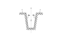
- the second width direction groove 3 has an inverted trapezoidal cross section in the reference state.
- FIG. 3B when the tire is in contact with the ground, the groove walls 3Wa and 3Wb of the second width direction groove 3 come into contact with each other on the tread tread surface T side due to the fall of the tread land portion, and the second width direction. The groove 3 is only partially closed.
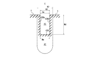
- FIG. 4 shows a second width direction groove 43 in another embodiment of the present invention.
- the second width direction groove 43 has a rectangular cross section in which the long side extends along the groove depth direction. That is, the groove walls 43Wa, 43Wb of the second width direction groove 43 extend toward the groove bottom along the opening center line C of the first width direction groove 42, and the tire wall inner ends in the tire radial direction of the groove walls 43Wa, 43Wb. Are connected to the groove bottom 43B.
- the groove width at the opening end of the second width direction groove 43 to the tread tread surface T (the groove width orthogonal to the extending direction of the second width direction groove 43, that is, the tire circumferential direction in the present embodiment). Length. The same applies to the following.)
- FIG. 5 shows a second width direction groove 53 in still another embodiment of the present invention as an example of the shape of the second width direction groove that is difficult to close even when the tire is in contact with the ground.
- the second width direction groove 53 has a trapezoidal cross section. That is, as the groove walls 53Wa and 53Wb of the second width direction groove 53 move toward the depth direction groove bottom 53B side of the second width direction groove 53, the distance from the opening center line C of the first width direction groove 52 increases.
- the groove bottom 53B is connected to the tire radial direction inner ends of the groove walls 53Wa and 53Wb.
- FIG. 6 shows a second width direction groove 63 in still another embodiment of the present invention as an example of the shape of the second width direction groove that is difficult to close even when the tire contacts the ground.
- the second width direction groove 63 has a cross section composed of a rectangular inlet portion opening in the tread tread surface T and an elliptical main body portion adjacent to the inner side in the tire radial direction of the inlet portion.
- the second width direction groove has the same groove width over the entire region in the depth direction including the opening end to the tread surface T, like the second width direction groove 43 shown in FIG.
- an opening end to the tread tread surface T such as the second width direction groove 3, the second width direction groove 53, and the second width direction groove 63 shown in FIGS.
- the groove width may be different in at least a part of the region in the depth direction.
- the latter (where the opening width to the tread tread T and at least a partial region in the depth direction have different groove widths of the second width direction groove) is toward the tread tread T of the second width direction groove. It is more preferable in that the attenuation characteristic of the resonance sound can be freely adjusted regardless of the groove width at the opening end of the.
- the second width direction groove is symmetric with respect to the opening center line C of the cross-sectional view width direction groove. Also good.
- only one second width direction groove is provided for each first width direction groove. A plurality of them may be provided in the same or different extending regions.
- the “cross-sectional area of the second width direction groove” in the above-mentioned “cross-sectional area of the second width direction groove / cross-sectional area of the first width direction groove” is the cross-sectional area of each second width direction groove.
- the second width direction groove extends along the extending direction of the first width direction groove in a developed view of the tread surface (ie, the first width). Extending at an angle of 0 ° with respect to the extending direction of the directional groove, as long as it communicates with the first width direction groove at both ends of the extending direction of the second width direction groove. It does not have to extend. However, from the viewpoint of ensuring a sufficient air flow toward the outer side in the tire width direction and more effective in reducing the air column resonance noise by the second width direction groove, the second width direction groove has the first width. It is preferable to extend along the extending direction of the directional groove.
- the second width direction groove is a groove that opens to the tread tread, but the second width direction groove is a tread tread that communicates with the first width direction groove at both ends in the extending direction. It may be a communicating hole that does not open. However, like the second width direction groove in the above-described embodiments, the communication hole needs not to be completely closed even when the tire is in contact with the ground.
- FIG. 7 is a partially enlarged view of the shoulder land portion 5S shown in FIG.
- the end of the second width direction groove 3 on the circumferential groove side 1 is a midpoint (first width direction) between the tire width direction inner end 2E of the first width direction groove 2 and the tread ground contact end TE.
- the groove 2 is located on the outer side in the tire width direction than the center 2C of the line segment connecting the tire width direction inner end 2E and the tread grounding end TE.
- the end on the circumferential groove side 1 of the second width direction groove 3 is located on the outer side in the tire width direction than the middle point 2C
- the end on the circumferential groove side 1 of the second width direction groove 3 is The air flow in the first width direction groove 2 closer to the circumferential groove 1 than the second width direction groove 3 is more compared to the case where the position is on the middle point or on the inner side in the tire width direction than the middle point 2C. This is because sufficient air can be secured, the air flowing into the second width direction groove 3 becomes faster, the damping effect due to viscosity increases, and the air column resonance can be further reduced. Further, as shown in FIG.
- the second width direction groove 3 divides the tire width direction distance between the tire width direction inner end 2E of the first width direction groove 2 and the tread ground contact end TE into four equal parts.
- the four tire width direction regions A, B, C, and D formed in this manner it is preferable to be located in the second tire width direction region C from the outer side in the tire width direction.
- the second width direction groove 3 since the second width direction groove 3 is always arranged in the ground contact surface of the tread, the effect of reducing the air column resonance noise by the second width direction groove 3 can be obtained more reliably. is there.
- first width direction grooves 2 having the second width direction grooves 3 are arranged in the contact surface of the tire (the surface that contacts the road surface when the tire contacts the ground). Furthermore, it is more preferable to arrange four or more.
- the resonance attenuation effect of the second width direction grooves 3 is proportional to the number of the first width direction grooves 2 having the second width direction grooves 3, but the rigidity of the shoulder land portion 5S is excessively reduced. From the viewpoint of avoiding this, it is preferable that the number is 6 or less.
- no grooves or sipes other than the first width direction groove 2 and the second width direction groove 3 are arranged in the shoulder land portion 5S, but depending on the intended tire performance, Various grooves, sipes, and the like can be arbitrarily provided.
- Various grooves, sipes, and the like can be arbitrarily provided in addition to the first width direction groove 2 provided with the second width direction groove 3, another width direction groove wider than the first width direction groove 2 may be provided.
- the center land portion 5C and the intermediate land portion 5M various grooves, sipes and the like can be arbitrarily provided according to the expected tire performance.
- Inventive tires 1-1 to 1-20 each have the tread pattern shown in FIG. 1 and have four circumferential grooves on the tread surface. Out of the circumferential grooves, both outermost circumferential directions in the tire width direction are provided. A plurality of first grooves communicating the circumferential groove and the tread grounding end that divide the land portion with the rib-shaped land portion (the shoulder land portion 5S in the above-described embodiment) partitioned by the groove and the tread grounding end. A width direction groove, a second width direction groove is provided in the first width direction groove, and each of the circumferential groove, the first width direction groove, and the second width direction groove has a “circumference”. The groove width of the direction groove 1> the groove width of the first width direction groove> the groove width of the second width direction groove ”.
- Comparative Example Tire 1-1 is the same tire as Invention Example Tire 1-1 except that it does not have the first width direction groove and the second width direction groove.
- the comparative example tire 1-2 has four circumferential grooves on the tread surface, and of the three rib-shaped land portions defined by the circumferential grooves, two rib-shaped land portions that do not include the tire equatorial plane A plurality of Helmholtz resonators that communicate with both circumferential grooves defining the land portion are provided (corresponding to the intermediate land portion 5M in the above-described embodiment).
- the comparative example tire 1-3 is the same tire as the example tire 1-1 except that the second width direction groove is not provided in the first width direction groove.
- the comparative example tire 1-4 is the same tire as the inventive example tire 1-1 except that the groove width of the first width direction groove is the same as the groove width of the circumferential groove.
- the comparative tire 1-5 is the same tire as the inventive tire 1-1 except that the groove width of the first width direction groove is larger than the groove width of the circumferential groove.
- the invention example tire 2-1 basically includes the tread pattern shown in FIG. 1 and has four circumferential grooves on the tread surface, and the circumferential grooves on both outermost sides in the tire width direction among the circumferential grooves.
- Directional grooves, and the second width direction grooves are included in the first width direction grooves, and the respective groove widths of the circumferential direction groove, the first width direction groove and the second width direction groove are defined as “circumferential direction
- the number of the first width direction grooves having the second width direction grooves that enter the ground contact surface of the tire is one for each of the rib-like land portions on both sides in the tire width direction.
- Comparative Example Tire 2-1 is the same as Invention Example Tire 2-1, except that the second width direction groove is not provided in the first width direction groove.
- Inventive tires 2-2 to 2-5 each have a number of first widthwise grooves having second widthwise grooves that enter the ground contact surface of the tire, 2 for each of the rib-like land portions on both sides in the tire width direction. Except for up to 5 tires, it is the same as the inventive tire 2-1.
- test / evaluation method of the test tire is the same as in Test 1.
- results are shown in Table 2 in terms of the amount of reduction (dB) relative to the comparative tire 2-1.
Landscapes
- Engineering & Computer Science (AREA)
- Mechanical Engineering (AREA)
- Tires In General (AREA)
Abstract
気柱共鳴音を低減しつつも、トレッドのデザインの自由度を維持し、かつ該トレッドにおける偏摩耗を抑制可能なタイヤを提供する。トレッド踏面に、タイヤ周方向に連続して延びる少なくとも1本の周方向溝と、該周方向溝とトレッド接地端とで区画されるショルダ陸部とを有するタイヤであって、前記ショルダ陸部は、タイヤ幅方向に延び前記周方向溝と前記トレッド接地端とを連通する、第1幅方向溝を有し、前記第1幅方向溝は、該第1幅方向溝内に、該第1幅方向溝に連通する第2幅方向溝を有し、前記周方向溝、前記第1幅方向溝及び前記第2幅方向溝の、それぞれの溝幅が、関係式「周方向溝の溝幅>第1幅方向溝の溝幅>第2幅方向溝の溝幅」を満足する。
Description
本発明は、タイヤに関する。
近年、走行中の自動車から生じる騒音においては、車両の静粛化に伴って、タイヤの負荷転動に起因する騒音の寄与が大きくなりその低減が求められている。中でも、高周波数、特に、1000Hz周辺のタイヤノイズが車外騒音の主たる原因となっており、環境問題の観点からもその低減対策が求められている。
この1000Hz周辺のタイヤノイズは、主に、気柱共鳴音によるものである。気柱共鳴音とは、トレッド踏面の周方向に連続して延びる周方向溝と路面とによって囲曉される、管内の空気の共鳴により発生する騒音であり、一般的な乗用車では800~1200Hz程度に観測されることが多い。かかる気柱共鳴音は、ピークレベルが高く、周波数帯域が広いことから、タイヤから発生する騒音の大部分を占めている。
また、人間の聴覚は、1000Hz周辺の周波数帯域で特に敏感であることから、走行時のフィーリング面での静粛性を向上させる上でも、このような気柱共鳴音の低減は有効である。
ここで、気柱共鳴音の低減を所期したタイヤとしては、例えば、複数本の周方向溝により区画されたリブ状陸部に、縦溝および横溝を有するサイドブランチ型の共鳴器を設けたもの(特許文献1)や、同陸部に、周方向溝に離間した位置で陸部表面に開口する気室と、該気室を周方向溝に連通させる1本以上の狭窄ネックと、を有するヘルムホルツ型の共鳴器を設けたもの(特許文献2)がある。
上述のサイドブランチ型およびヘルムホルツ型の共鳴器においては、トレッドの陸部に大きなまたは複雑な形状の溝や凹部を設ける必要があることから、トレッドのデザインの自由度が制限されたり、陸部の剛性分布が不均一になり、偏摩耗の原因となる虞があった。
そこで、本発明は、気柱共鳴音を低減しつつも、トレッドのデザインの自由度を維持し、かつ該トレッドにおける偏摩耗を抑制可能なタイヤを提供することを目的とする。
本発明のタイヤは、トレッド踏面に、タイヤ周方向に連続して延びる少なくとも1本の周方向溝と、該周方向溝とトレッド接地端とで区画されるショルダ陸部とを有するタイヤであって、前記ショルダ陸部は、タイヤ幅方向に延び前記周方向溝と前記トレッド接地端とを連通する、第1幅方向溝を有し、前記第1幅方向溝は、該第1幅方向溝内に、該第1幅方向溝に連通する第2幅方向溝を有し、前記周方向溝、前記第1幅方向溝及び前記第2幅方向溝の、それぞれの溝幅が、関係式「周方向溝の溝幅>第1幅方向溝の溝幅>第2幅方向溝の溝幅」を満足することを特徴とする。かかる構成の本発明のタイヤによれば、気柱共鳴音を低減しつつも、トレッドのデザインの自由度を維持し、かつ該トレッドにおける偏摩耗を抑制することができる。
ここで、本明細書において、「トレッド踏面」とは、リムに組み付けるとともに所定の内圧を充填したタイヤを、最大負荷荷重を負荷した状態で転動させた際に、路面と接触することになる、タイヤの全周に亘る外周面を意味し、「トレッド接地端」とは、トレッド踏面のタイヤ幅方向端を意味する。
また、本明細書において、「基準状態」とは、タイヤをリムに組み付け、所定の内圧を充填し、無負荷とした状態を指し、「タイヤの接地時」とは、タイヤをリムに組み付け、所定の内圧を充填し、最大負荷荷重を負荷した状態で、平坦な路面上に静止させたときを指す。
上記の「リム」とは、タイヤが生産され、使用される地域に有効な産業規格であって、日本ではJATMA(日本自動車タイヤ協会)のJATMA YEAR BOOK、欧州ではETRTO (The European Tyre and Rim Technical Organisation)のSTANDARDS MANUAL、米国ではTRA (The Tire and Rim Association, Inc.)のYEAR BOOK等に記載されているまたは将来的に記載される、適用サイズにおける標準リム(ETRTOのSTANDARDS MANUALではMeasuring Rim、TRAのYEAR BOOKではDesign Rim)を指す(すなわち、上記の「リム」には、現行サイズに加えて将来的に上記産業規格に含まれ得るサイズも含む。「将来的に記載されるサイズ」の例としては、ETRTOのSTANDARDS MANUAL 2013年度版において「FUTURE DEVELOPMENTS」として記載されているサイズを挙げることができる。)が、上記産業規格に記載のないサイズの場合は、タイヤのビード幅に対応した幅のリムをいう。
また、「所定の内圧」とは、上記のJATMA YEAR BOOK等に記載されている、適用サイズ・プライレーティングにおける単輪の最大負荷能力に対応する空気圧(最高空気圧)をいい、上記産業規格に記載のないサイズの場合は、「所定の内圧」は、タイヤを装着する車両ごとに規定される最大負荷能力に対応する空気圧(最高空気圧)をいうものとする。さらに、「最大負荷荷重」とは、上記最大負荷能力に対応する荷重をいうものとする。
なお、ここでいう空気は、窒素ガス等の不活性ガスその他に置換することも可能である。
また、本明細書において、「基準状態」とは、タイヤをリムに組み付け、所定の内圧を充填し、無負荷とした状態を指し、「タイヤの接地時」とは、タイヤをリムに組み付け、所定の内圧を充填し、最大負荷荷重を負荷した状態で、平坦な路面上に静止させたときを指す。
上記の「リム」とは、タイヤが生産され、使用される地域に有効な産業規格であって、日本ではJATMA(日本自動車タイヤ協会)のJATMA YEAR BOOK、欧州ではETRTO (The European Tyre and Rim Technical Organisation)のSTANDARDS MANUAL、米国ではTRA (The Tire and Rim Association, Inc.)のYEAR BOOK等に記載されているまたは将来的に記載される、適用サイズにおける標準リム(ETRTOのSTANDARDS MANUALではMeasuring Rim、TRAのYEAR BOOKではDesign Rim)を指す(すなわち、上記の「リム」には、現行サイズに加えて将来的に上記産業規格に含まれ得るサイズも含む。「将来的に記載されるサイズ」の例としては、ETRTOのSTANDARDS MANUAL 2013年度版において「FUTURE DEVELOPMENTS」として記載されているサイズを挙げることができる。)が、上記産業規格に記載のないサイズの場合は、タイヤのビード幅に対応した幅のリムをいう。
また、「所定の内圧」とは、上記のJATMA YEAR BOOK等に記載されている、適用サイズ・プライレーティングにおける単輪の最大負荷能力に対応する空気圧(最高空気圧)をいい、上記産業規格に記載のないサイズの場合は、「所定の内圧」は、タイヤを装着する車両ごとに規定される最大負荷能力に対応する空気圧(最高空気圧)をいうものとする。さらに、「最大負荷荷重」とは、上記最大負荷能力に対応する荷重をいうものとする。
なお、ここでいう空気は、窒素ガス等の不活性ガスその他に置換することも可能である。
さらに、本明細書において、「周方向溝の溝幅」は、基準状態で測定した、周方向溝の延在方向に直交する向きの長さをいうものとする。同様に、「第1幅方向溝の溝幅」および「第2幅方向溝の溝幅」は、基準状態で測定した、当該第2幅方向溝を有する当該第1幅方向溝の延在方向に直交する向きの長さをいうものとする。
なお、上記のいずれの溝においても、溝の深さ方向に沿って溝幅が変化する場合は、深さ方向の測定位置等の条件の指定が特にない限り、その最大幅をもって溝幅(以下の実施形態では、W1,W2,W3で示す)とする。
以下、特に断りのない限り、溝等の各要素の寸法等は、基準状態で(各要素のトレッド踏面における寸法等は、基準状態におけるトレッド踏面の展開図上で)測定されるものとする。
なお、上記のいずれの溝においても、溝の深さ方向に沿って溝幅が変化する場合は、深さ方向の測定位置等の条件の指定が特にない限り、その最大幅をもって溝幅(以下の実施形態では、W1,W2,W3で示す)とする。
以下、特に断りのない限り、溝等の各要素の寸法等は、基準状態で(各要素のトレッド踏面における寸法等は、基準状態におけるトレッド踏面の展開図上で)測定されるものとする。
本発明によれば、気柱共鳴音を低減しつつも、トレッドのデザインの自由度を維持し、かつ該トレッドにおける偏摩耗を抑制可能なタイヤを提供することができる。
以下に、図面を参照しながら、本発明に係るタイヤの実施形態を例示説明する。
図1は、本発明の一実施形態に係るタイヤ10のトレッド踏面Tを模式的に示す、展開図である。タイヤ10は、トレッド踏面Tに、タイヤ周方向に連続して延びる(図示例では、タイヤ周方向に沿って、すなわち、タイヤ周方向に対して0°の角度で、タイヤ周方向に連続して延びる)少なくとも1本(図示例では、4本)の周方向溝1を有し、該4本の周方向溝1と両トレッド接地端TEと、により、タイヤ赤道面TCを含む1つのセンター陸部5Cと、該センター陸部5Cのタイヤ幅方向両外側に周方向溝1を介して隣接する2つの中間陸部5Mと、該中間陸部のタイヤ幅方向両外側に周方向溝1を介して隣接する2つのショルダ陸部5Sと、が区画形成されている。本実施形態における周方向溝1は、タイヤ周方向に沿ってタイヤ周方向に連続して延びる、直線状の溝であるが、本発明のタイヤにおいて、周方向溝1は、タイヤ周方向(タイヤ赤道面TC)に対して傾斜してタイヤ周方向に連続して延びる、ジグザグ状や波状の溝とすることもできる。本発明のタイヤにおいて、周方向溝1は、少なくとも1本あればよく、本実施形態では4本であるが、これに限らず複数本あるのが好ましい。複数本の場合、2本、3本または5本以上であってもよい。
以上のとおり、本実施形態のタイヤ10は、トレッド踏面Tに、タイヤ周方向に連続して延びる少なくとも1本の周方向溝1と、該周方向溝1とトレッド接地端TEとで区画されるショルダ陸部5Sとを有している。
なお、本実施形態のタイヤは、乗用車用の空気入りラジアルタイヤであるが、本発明は、気柱共鳴音低減の要請のあるこれ以外の種類のタイヤにも適用可能である。
図1は、本発明の一実施形態に係るタイヤ10のトレッド踏面Tを模式的に示す、展開図である。タイヤ10は、トレッド踏面Tに、タイヤ周方向に連続して延びる(図示例では、タイヤ周方向に沿って、すなわち、タイヤ周方向に対して0°の角度で、タイヤ周方向に連続して延びる)少なくとも1本(図示例では、4本)の周方向溝1を有し、該4本の周方向溝1と両トレッド接地端TEと、により、タイヤ赤道面TCを含む1つのセンター陸部5Cと、該センター陸部5Cのタイヤ幅方向両外側に周方向溝1を介して隣接する2つの中間陸部5Mと、該中間陸部のタイヤ幅方向両外側に周方向溝1を介して隣接する2つのショルダ陸部5Sと、が区画形成されている。本実施形態における周方向溝1は、タイヤ周方向に沿ってタイヤ周方向に連続して延びる、直線状の溝であるが、本発明のタイヤにおいて、周方向溝1は、タイヤ周方向(タイヤ赤道面TC)に対して傾斜してタイヤ周方向に連続して延びる、ジグザグ状や波状の溝とすることもできる。本発明のタイヤにおいて、周方向溝1は、少なくとも1本あればよく、本実施形態では4本であるが、これに限らず複数本あるのが好ましい。複数本の場合、2本、3本または5本以上であってもよい。
以上のとおり、本実施形態のタイヤ10は、トレッド踏面Tに、タイヤ周方向に連続して延びる少なくとも1本の周方向溝1と、該周方向溝1とトレッド接地端TEとで区画されるショルダ陸部5Sとを有している。
なお、本実施形態のタイヤは、乗用車用の空気入りラジアルタイヤであるが、本発明は、気柱共鳴音低減の要請のあるこれ以外の種類のタイヤにも適用可能である。
また、ショルダ陸部5Sは、タイヤ幅方向に延び周方向溝1とトレッド接地端TEとを連通する、本実施形態では互いにタイヤ周方向に離隔して配置された複数本(図示例では、そのうちの1本を示している)の、第1幅方向溝2を有し、該第1幅方向溝2によって、タイヤ周方向に複数のブロック状陸部が形成されている。この第1幅方向溝2は、該第1幅方向溝2内に、第1幅方向溝2に連通する第2幅方向溝3を有している。第2幅方向溝3は、第1幅方向溝2が周方向溝1とトレッド接地端TEとを連通できるように、第2幅方向溝3の延在方向の両端で第1幅方向溝2に連通している。本実施形態における第1幅方向溝2の溝幅W2は、周方向溝1の溝幅W1よりも小さい。より詳細には、当該第1幅方向溝2は、溝幅が例えば2mm程の細溝であり、第2幅方向溝3の配置されている領域を除き、該溝幅がタイヤ幅方向の全域に亘って一定である。第1幅方向溝2は、周方向溝1よりも、断面積が小さいこと、および/または、溝深さが小さいことが好ましい。本実施形態では、第1幅方向溝2は、タイヤ幅方向に沿って(すなわち、タイヤ幅方向に対して0°の角度で)延びているが、第1幅方向溝2は、タイヤ幅方向に対して例えば45°以内の角度で傾斜して延びていてもよく、タイヤ幅方向成分を有していればよい。
第2幅方向溝3について、図2を用いて説明する。図2は、図1に示すA-A線における断面図であり、第1幅方向溝2内に設けられた第2幅方向溝3の、第1幅方向溝2の延在方向に直交する面による断面を示している。なお、ここでは説明のため、第1幅方向溝2の溝壁2Wa,2Wbおよび溝底2Bの形状を破線にて示している。図示するように、第2幅方向溝3は、第1幅方向溝2よりも深さが浅く、溝幅W3が狭くされている。第2幅方向溝3の溝壁(第2幅方向溝3を区画する両溝壁)3Wa,3Wbは、該第2幅方向溝3の深さ方向溝底3B側に向かうに従い、第1幅方向溝2の開口中心線Cに近づく方向に傾斜して延び、それらのタイヤ径方向内側端を、第2幅方向溝3の溝底3Bが繋いでいる。よって、本実施形態における第2幅方向溝3は、逆台形の断面を有している。
ここで、本発明のタイヤでは、周方向溝1、第1幅方向溝2及び第2幅方向溝3の、それぞれの溝幅が、関係式「周方向溝1の溝幅W1>第1幅方向溝2の溝幅W2>第2幅方向溝3の溝幅W3」を満足することが必要である。
上述のとおり、車両走行時においては、周方向溝1と路面とによって囲曉される管内の空気が共鳴する、共鳴音が生じるが、本発明のタイヤでは、周方向溝1と第1幅方向溝2と第2幅方向溝3との溝幅W1,W2,W3が上記関係を満たすようにされているため、かかる共鳴音を、第2幅方向溝3を介して低減することができる。より具体的には、車両走行中に周方向溝1に流入し周方向溝1を通過する空気(音波)は、第1幅方向溝2を介してタイヤ幅方向外側へも移動するが、空気が第2幅方向溝3を通過する際の粘性摩擦(第2幅方向溝3にて空気が絞られることによる摩擦)によって、該空気の運動エネルギーが熱エネルギーに変換され、この熱エネルギーが、外部へ放出され、または、第2幅方向溝3の溝壁3Wa,3Wbや溝底3B等へ吸収されることにより、共鳴音が低減される。このように、本発明のタイヤでは、第2幅方向溝3、特にその入口と出口における、空気の粘性による音波の減衰効果を利用することによって、気柱共鳴音を低減することができる。さらに、本発明のタイヤでは、従来の、ブランチ型やヘルムホルツ型の共鳴器のような、大きなまたは複雑な形状の溝や凹部をトレッド踏面に設ける必要がなく、第2幅方向溝2内に狭幅の第2幅方向溝3を設けるだけでよいので、トレッドのデザインの自由度を維持することができ、さらに、トレッドの陸部剛性が不均一になり難いので、トレッド踏面における偏摩耗を抑制することができる。すなわち、本発明のタイヤでは、トレッド踏面に特定の共鳴器を配設せずとも、第1幅方向溝2内において気柱共鳴音を減衰できるため、トレッドのデザインの自由度を妨げることなく、また、トレッドの陸部剛性を均一に保ちながら、気柱共鳴音を低減することができる。但し、他の共鳴器を設けてもよい。
上述のとおり、車両走行時においては、周方向溝1と路面とによって囲曉される管内の空気が共鳴する、共鳴音が生じるが、本発明のタイヤでは、周方向溝1と第1幅方向溝2と第2幅方向溝3との溝幅W1,W2,W3が上記関係を満たすようにされているため、かかる共鳴音を、第2幅方向溝3を介して低減することができる。より具体的には、車両走行中に周方向溝1に流入し周方向溝1を通過する空気(音波)は、第1幅方向溝2を介してタイヤ幅方向外側へも移動するが、空気が第2幅方向溝3を通過する際の粘性摩擦(第2幅方向溝3にて空気が絞られることによる摩擦)によって、該空気の運動エネルギーが熱エネルギーに変換され、この熱エネルギーが、外部へ放出され、または、第2幅方向溝3の溝壁3Wa,3Wbや溝底3B等へ吸収されることにより、共鳴音が低減される。このように、本発明のタイヤでは、第2幅方向溝3、特にその入口と出口における、空気の粘性による音波の減衰効果を利用することによって、気柱共鳴音を低減することができる。さらに、本発明のタイヤでは、従来の、ブランチ型やヘルムホルツ型の共鳴器のような、大きなまたは複雑な形状の溝や凹部をトレッド踏面に設ける必要がなく、第2幅方向溝2内に狭幅の第2幅方向溝3を設けるだけでよいので、トレッドのデザインの自由度を維持することができ、さらに、トレッドの陸部剛性が不均一になり難いので、トレッド踏面における偏摩耗を抑制することができる。すなわち、本発明のタイヤでは、トレッド踏面に特定の共鳴器を配設せずとも、第1幅方向溝2内において気柱共鳴音を減衰できるため、トレッドのデザインの自由度を妨げることなく、また、トレッドの陸部剛性を均一に保ちながら、気柱共鳴音を低減することができる。但し、他の共鳴器を設けてもよい。
また、本発明に係るタイヤでは、第1幅方向溝2の溝幅W2と周方向溝1の溝幅W1との比(W2/W1)が、0.1以上0.5以下であることが好ましい。0.1以上であれば、第1幅方向溝2に十分な量の空気を送り込むことができるため、気柱共鳴音をさらに低減させることができる。また、0.5以下であれば、第1幅方向溝2にて、周方向溝1から流れ込む空気を十分に絞り、比較的高速な空気を第2幅方向溝3に送り込むことができるため、気柱共鳴音をさらに低減させることができるとともに、トレッドのデザインの自由度をより十分に確保することができ、さらにトレッドにおける偏摩耗をより抑制することができる。また、0.5以下であれば、パターンノイズを低減できる。上記比は、0.2以上0.4以下であることが、同様の理由からさらに好ましい。
また、第2幅方向溝3の溝幅W3と第1幅方向溝2の溝幅W2との比(W3/W2)が、0.1以上0.8以下であることが好ましい。0.1以上であれば、第2幅方向溝3に十分な量の空気を送り込むことができるため、気柱共鳴音をさらに低減させることができる。また、0.8以下であれば、第2幅方向溝3にて、第1幅方向溝2から流れ込む空気を十分に絞ることができるため、気柱共鳴音をさらに低減させることができる。上記比は、0.2以上0.6以下であることが、同様の理由からさらに好ましい。
なお、各溝において、溝の延在方向に沿って溝幅が変化する場合は、以下の位置における溝幅をもって、当該溝の溝幅とする。すなわち、第2幅方向溝の溝幅が当該第2幅方向溝の延在方向に沿って変化する場合、第2幅方向溝と当該第2幅方向溝が連通する第1幅方向溝との境界位置における第2幅方向溝の溝幅を、第2幅方向溝の溝幅とし、第1幅方向溝の溝幅が当該第1幅方向溝の延在方向に沿って変化する場合、その最大の溝幅を、第1幅方向溝の溝幅とする。
第1幅方向溝の溝幅と第2幅方向溝の溝幅とは、両溝の境界位置で連続的かつ滑らかに変化していてもよいが、気柱共鳴音の低減効果を高める観点からは、両溝の境界位置で連続的かつ滑らかでなく変化していることが好ましい。但し、第1幅方向溝の溝幅と第2幅方向溝の溝幅とは、気柱共鳴音の低減効果をより高める観点からは、本実施形態のように、両溝の境界位置で断続的に変化している(当該境界位置(境界面)における、第1幅方向溝の溝幅と第2幅方向溝の溝幅とが異なっている)ことが特に好ましい。
第1幅方向溝の溝幅と第2幅方向溝の溝幅とは、両溝の境界位置で連続的かつ滑らかに変化していてもよいが、気柱共鳴音の低減効果を高める観点からは、両溝の境界位置で連続的かつ滑らかでなく変化していることが好ましい。但し、第1幅方向溝の溝幅と第2幅方向溝の溝幅とは、気柱共鳴音の低減効果をより高める観点からは、本実施形態のように、両溝の境界位置で断続的に変化している(当該境界位置(境界面)における、第1幅方向溝の溝幅と第2幅方向溝の溝幅とが異なっている)ことが特に好ましい。
また、本発明に係るタイヤでは、第2幅方向溝3の溝底3Bと第1幅方向溝2の溝底2Bとの距離d1が、1.0mm以上であることが好ましい。これは、第1幅方向溝2の溝底2Bの近傍を流れる空気は、該溝底2Bとの摩擦の影響を受けて低速であるが、溝底2Bから1mm以上離間した領域を流れる空気は十分に高速であり、この十分に高速な空気層が第2幅方向溝3を通過することによって、粘性による減衰効果が増し、気柱共鳴音をさらに低減できるからである。
さらに、第2幅方向溝3の溝壁3Wa,3Wbと第1幅方向溝2の溝壁2Wa,2Wbとの距離d2が、0.25mm以上であることが好ましい。これは、第1幅方向溝2の溝壁2Wa,2Wbの近傍を流れる空気は、該溝壁2Wa,2Wbとの摩擦の影響を受けて低速であるが、溝壁2Wa,2Wbから0.25mm以上離間した領域を流れる空気は比較的高速であり、この比較的高速な空気が第2幅方向溝3を通過することによって、粘性による減衰効果が増し、気柱共鳴音をさらに低減できるからである。
なお、「第2幅方向溝の溝底と第1幅方向溝の溝底との距離」および「第2幅方向溝の溝壁と第1幅方向溝の溝壁との距離」とは、両溝底間および両溝壁間の最短の長さをいうものとする。
また、第2幅方向溝3の溝壁3Wa,3Wbの表面の少なくとも一部に凹凸加工を施し、該表面の算術平均粗さRaを1.0μm以上5.0μm以下とすることが好ましい。この場合、第2幅方向溝3におけるエネルギー損失が増し、気柱共鳴音をさらに低減できるからである。なお、「算術平均粗さRa」とは、JIS B 0601(2001年)に規定の「算術平均粗さRa」であり、単位長さを10mmとして求めたものである。
また、第2幅方向溝3の断面積と第1幅方向溝2の断面積とが、「0.08≦第2幅方向溝3の断面積/第1幅方向溝2の断面積≦0.80」を満足することが好ましい。すなわち、図2において、第1幅方向溝2のタイヤ周方向一方側のトレッド踏面Tとタイヤ周方向他方側のトレッド踏面Tとを滑らかにつなぐ仮想線Lと、第2幅方向溝3の溝壁3Wa,3Wbと、溝底3Bと、によって囲まれる第2幅方向溝3の断面積が、上記仮想線Lと、第1幅方向溝2の溝壁2Wa,2Wbと、溝底2Bと、によって囲まれる第1幅方向溝2の断面積の、0.08倍以上0.80倍以下であることが好ましい、ということである。
第2幅方向溝の断面積が第1幅方向溝2の断面積の0.08倍以上の場合、十分な量の空気が第2幅方向溝3を通過し、第2幅方向溝3において十分な減衰効果が得られるため、気柱共鳴音をさらに低減することができる。また、0.8倍以下の場合、第2幅方向溝3において十分に空気を絞ることができ、第2幅方向溝3における減衰効果が大きくなるため、気柱共鳴音をさらに低減することができる。
気柱共鳴音をさらに低減する観点から言えば、第2幅方向溝3の断面積を第1幅方向溝2の断面積の0.5倍以下とすることが好ましい。0.5倍以下とすることにより、第2幅方向溝3における減衰効果が増し、気柱共鳴音がより低減するからである。同様の理由から、第2幅方向溝3の断面積を第1幅方向溝2の断面積の0.4倍以下とすることが、さらに好ましい。
なお、図示はしていないが、本発明のタイヤにおいて、第2幅方向溝の断面積が当該第2幅方向溝の延在方向に沿って変化する場合、第2幅方向溝と当該第2幅方向溝が連通する第1幅方向溝との境界位置における第2幅方向溝の断面積を、第2幅方向溝の断面積とし、第1幅方向溝の断面積が当該第1幅方向溝の延在方向に沿って変化する場合、その最大断面積を、第1幅方向溝の断面積とする。
第1幅方向溝の断面積と第2幅方向溝の断面積とは、両溝の境界位置で連続的かつ滑らかに変化していてもよいが、気柱共鳴音の低減効果を高める観点からは、両溝の境界位置で連続的かつ滑らかでなく変化していることが好ましい。また、同様の観点から、両溝の境界位置から第1幅方向溝の延在方向第1幅方向溝側に例えば1.0mm以下離隔した位置(当該境界位置も含む)における第1幅方向溝の断面積に対する第2幅方向溝の断面積が、上述の所定の断面積比になるように、第1幅方向溝の断面積が急激に減少して第2幅方向溝に至るような構成であることが、さらに好ましい。但し、第1幅方向溝の断面積と第2幅方向溝の断面積とは、気柱共鳴音の低減効果をより高める観点からは、本実施形態のように、両溝の境界位置で断続的に変化している(当該境界位置(境界面)における、第1幅方向溝の断面積と第2幅方向溝の断面積とが、異なっている)ことが特に好ましい。
第1幅方向溝の断面積と第2幅方向溝の断面積とは、両溝の境界位置で連続的かつ滑らかに変化していてもよいが、気柱共鳴音の低減効果を高める観点からは、両溝の境界位置で連続的かつ滑らかでなく変化していることが好ましい。また、同様の観点から、両溝の境界位置から第1幅方向溝の延在方向第1幅方向溝側に例えば1.0mm以下離隔した位置(当該境界位置も含む)における第1幅方向溝の断面積に対する第2幅方向溝の断面積が、上述の所定の断面積比になるように、第1幅方向溝の断面積が急激に減少して第2幅方向溝に至るような構成であることが、さらに好ましい。但し、第1幅方向溝の断面積と第2幅方向溝の断面積とは、気柱共鳴音の低減効果をより高める観点からは、本実施形態のように、両溝の境界位置で断続的に変化している(当該境界位置(境界面)における、第1幅方向溝の断面積と第2幅方向溝の断面積とが、異なっている)ことが特に好ましい。
さらに、第2幅方向溝3の、第1幅方向溝2の延在方向に沿う延在長さX(図7参照)を、1.0mm以上3.0mm以下とすることが好ましい。1.0mm以上とすれば、第1幅方向溝2を設けたことによるショルダ陸部5Sの剛性の低下を抑制することができる。また、上述した、第2幅方向溝3における減衰効果は、当該延在長さXに特に比例しないため、3.0mm以下であれば十分である。
また、第2幅方向溝3は、「周方向溝1の溝幅W1>第1幅方向溝2の溝幅W2」である限り、任意の溝幅を有する第1幅方向溝2への配設が可能であるが、特に、溝幅W2が1.0mm以上3.0mm以下である、溝幅が比較的小さい第1幅方向溝2に設けることにより、第1幅方向溝2を設けたことによるショルダ陸部5Sの剛性の低下を抑制しつつ、気柱共鳴音をより効果的に低減することができる。
また、本発明のタイヤにおいて、第2幅方向溝3の、第1幅方向溝2に直交する断面における形状は、逆台形に限らず任意の形状とすることができるが、本発明の作用効果を得るためには、タイヤの接地時に、第2幅方向溝3が少なくとも完全には閉じ難い形状とする必要がある。本実施形態において、第2幅方向溝3は、図3Aに示すように、基準状態においては逆台形の断面を有する。しかしながら、図3Bに示すように、タイヤの接地時においては、トレッド陸部の倒れ込みによって第2幅方向溝3の溝壁3Wa,3Wbがトレッド踏面T側で相互に接触し、該第2幅方向溝3が部分的にのみ閉じる。
タイヤの接地時においても閉じ難い第2幅方向溝の形状の一例として、図4に、本発明の他の実施形態における第2幅方向溝43を示す。第2幅方向溝43は、長辺が溝深さ方向に沿って延びる、長方形の断面を有する。すなわち、第2幅方向溝43の溝壁43Wa,43Wbが、第1幅方向溝42の開口中心線Cに沿って溝底に向かって延在し、溝壁43Wa,43Wbのタイヤ径方向内側端を、溝底43Bがつないでいる。なお、この例では、第2幅方向溝43の、トレッド踏面Tへの開口端における溝幅(第2幅方向溝43の延在方向に直交する溝幅、すなわち、本実施形態ではタイヤ周方向長さ。以下も同様。)Owと、溝底43Bにおける溝幅Mwと、溝深さ(タイヤ径方向長さ)Mdと、の比は、1:1:3である。より具体的に、本実施形態では、例えば、Ow=Mw=1mm、Md=3mmである。なお、本実施形態では、上記溝幅Owと上記溝幅Mwとはともに、本明細書で定義する溝幅W3に等しい。
同様に、タイヤの接地時においても閉じ難い第2幅方向溝の形状の一例として、図5に、本発明のさらに他の実施形態における第2幅方向溝53を示す。第2幅方向溝53は、台形の断面を有する。すなわち、第2幅方向溝53の溝壁53Wa,53Wbが、該第2幅方向溝53の深さ方向溝底53B側に向かうに従い、第1幅方向溝52の開口中心線Cから離れる方向に延在し、溝壁53Wa,53Wbのタイヤ径方向内側端を、溝底53Bがつないでいる。なお、この例では、第2幅方向溝53の、トレッド踏面Tへの開口端における溝幅Owと、溝底53Bにおける溝幅Mwと、溝深さMdと、の比は、1:3:8である。より具体的に、本実施形態では、例えば、Ow=0.5mm、Mw=1.5mm、Md=4mmである。なお、当該比を、1:2:6(例えば、Ow=0.5mm、Mw=1mm、Md=3mm)等とすることもできる。なお、本実施形態では、Mw=W3である。
同様に、タイヤの接地時においても閉じ難い第2幅方向溝の形状の一例として、図6に、本発明のさらに他の実施形態における第2幅方向溝63を示す。第2幅方向溝63は、トレッド踏面Tに開口する矩形の入口部と、該入口部のタイヤ径方向内側に隣接する楕円形の本体部と、からなる断面を有する。なお、この例では、第2幅方向溝63の、トレッド踏面Tへの開口端における溝幅Owと、本体部の溝幅Mwと、溝深さMdと、の比は、1:3:8である。より具体的に、本実施形態では、例えば、Ow=0.5mm、Mw=1.5mm、Md=4mmである。なお、本実施形態では、Mw=W3である。
なお、図2に示した、逆台形の断面を有する第2幅方向溝3では、該第2幅方向溝3の、トレッド踏面Tへの開口端における溝幅Owと、溝底3Bにおける溝幅Mwと、溝深さMdと、の比が、3以上:2:6である。より具体的に、本実施形態では、例えば、Ow=1.5mmまたはそれ以上、Mw=1mm、Md=3mmである。なお、本実施形態では、Ow=W3である。
以上述べたように、第2幅方向溝は、図4に示す第2幅方向溝43のように、トレッド踏面Tへの開口端を含む深さ方向の全域に亘ってその溝幅が同じであってもよいが、例えば、図2、図5および図6に示す第2幅方向溝3、第2幅方向溝53および第2幅方向溝63のように、トレッド踏面Tへの開口端と深さ方向の少なくとも一部の領域とでその溝幅が異なっていてもよい。後者(トレッド踏面Tへの開口端と深さ方向の少なくとも一部の領域とで、第2幅方向溝の溝幅が異なっているもの)の方が、第2幅方向溝のトレッド踏面Tへの開口端における溝幅によらずに共鳴音の減衰特性を自由に調整できる、という点では、より好ましい。
なお、上述の各実施形態では、図2~6に示すとおり、第2幅方向溝は、断面視幅方向溝の開口中心線Cに対し左右対称形状とされているが、非対称形状であってもよい。
また、上述の各実施形態では、図1~6に示すとおり、第2幅方向溝は、1つの第1幅方向溝に対し1つのみ設けられているが、1つの第1幅方向溝内の同一のまたは異なる延在領域内に、合わせて複数設けられていてもよい。この場合、上述した「第2幅方向溝の断面積/第1幅方向溝の断面積」における「第2幅方向溝の断面積」は、個々の第2幅方向溝の断面積とするものとする。
さらに上述の各実施形態では、図1および後述の図7に示すとおり、第2幅方向溝は、トレッド踏面の展開視で第1幅方向溝の延在方向に沿って(すなわち、第1幅方向溝の延在方向に対し0°の角度で)延びているが、当該第2幅方向溝の延在方向両端で第1幅方向溝に連通している限り、第1幅方向溝に沿って延びていなくてもよい。但し、タイヤ幅方向外側への空気の流れを十分確保し、第2幅方向溝による気柱共鳴音の低減効果をより十分なものとする観点からは、第2幅方向溝は、第1幅方向溝の延在方向に沿って延びていることが好ましい。
さらに、以上述べたところでは、第2幅方向溝は、トレッド踏面に開口する溝とされているが、第2幅方向溝は、延在方向両端で第1幅方向溝に連通する、トレッド踏面には開口しない連通孔とされていてもよい。但し、当該連通孔は、上述の各実施形態における第2幅方向溝と同様に、タイヤの接地時にも完全には閉じないものである必要がある。
なお、上述の各実施形態では、図2~6に示すとおり、第2幅方向溝は、断面視幅方向溝の開口中心線Cに対し左右対称形状とされているが、非対称形状であってもよい。
また、上述の各実施形態では、図1~6に示すとおり、第2幅方向溝は、1つの第1幅方向溝に対し1つのみ設けられているが、1つの第1幅方向溝内の同一のまたは異なる延在領域内に、合わせて複数設けられていてもよい。この場合、上述した「第2幅方向溝の断面積/第1幅方向溝の断面積」における「第2幅方向溝の断面積」は、個々の第2幅方向溝の断面積とするものとする。
さらに上述の各実施形態では、図1および後述の図7に示すとおり、第2幅方向溝は、トレッド踏面の展開視で第1幅方向溝の延在方向に沿って(すなわち、第1幅方向溝の延在方向に対し0°の角度で)延びているが、当該第2幅方向溝の延在方向両端で第1幅方向溝に連通している限り、第1幅方向溝に沿って延びていなくてもよい。但し、タイヤ幅方向外側への空気の流れを十分確保し、第2幅方向溝による気柱共鳴音の低減効果をより十分なものとする観点からは、第2幅方向溝は、第1幅方向溝の延在方向に沿って延びていることが好ましい。
さらに、以上述べたところでは、第2幅方向溝は、トレッド踏面に開口する溝とされているが、第2幅方向溝は、延在方向両端で第1幅方向溝に連通する、トレッド踏面には開口しない連通孔とされていてもよい。但し、当該連通孔は、上述の各実施形態における第2幅方向溝と同様に、タイヤの接地時にも完全には閉じないものである必要がある。
また、図7は、図1に示したショルダ陸部5Sの部分拡大図である。
第2幅方向溝3の周方向溝側1の端は、図7に示すように、第1幅方向溝2のタイヤ幅方向内側端2Eとトレッド接地端TEとの中点(第1幅方向溝2のタイヤ幅方向内側端2Eとトレッド接地端TEとを結んだ線分の中点)2Cよりもタイヤ幅方向外側に位置していることが好ましい。第2幅方向溝3の周方向溝側1の端が、上記中点2Cよりもタイヤ幅方向外側に位置している場合、第2幅方向溝3の周方向溝側1の端が、上記中点上または上記中点2Cよりもタイヤ幅方向内側に位置している場合と比較して、第2幅方向溝3より周方向溝1側の第1幅方向溝2における空気の流れをより十分確保でき、第2幅方向溝3に流れ込む空気がより高速になって、粘性による減衰効果が増し、気柱共鳴音をさらに低減できるからである。
また、第2幅方向溝3の少なくとも一部が、図7に示すように、第1幅方向溝2のタイヤ幅方向内側端2Eとトレッド接地端TEとのタイヤ幅方向距離を4等分して形成される4つのタイヤ幅方向領域A、B、C、Dのうち、タイヤ幅方向外側から2番目のタイヤ幅方向領域Cに位置していることが好ましい。この場合、第2幅方向溝3が常にトレッドの接地面内に配置されることになるため、該第2幅方向溝3による気柱共鳴音の低減効果をより確実に得ることができるからである。
第2幅方向溝3の周方向溝側1の端は、図7に示すように、第1幅方向溝2のタイヤ幅方向内側端2Eとトレッド接地端TEとの中点(第1幅方向溝2のタイヤ幅方向内側端2Eとトレッド接地端TEとを結んだ線分の中点)2Cよりもタイヤ幅方向外側に位置していることが好ましい。第2幅方向溝3の周方向溝側1の端が、上記中点2Cよりもタイヤ幅方向外側に位置している場合、第2幅方向溝3の周方向溝側1の端が、上記中点上または上記中点2Cよりもタイヤ幅方向内側に位置している場合と比較して、第2幅方向溝3より周方向溝1側の第1幅方向溝2における空気の流れをより十分確保でき、第2幅方向溝3に流れ込む空気がより高速になって、粘性による減衰効果が増し、気柱共鳴音をさらに低減できるからである。
また、第2幅方向溝3の少なくとも一部が、図7に示すように、第1幅方向溝2のタイヤ幅方向内側端2Eとトレッド接地端TEとのタイヤ幅方向距離を4等分して形成される4つのタイヤ幅方向領域A、B、C、Dのうち、タイヤ幅方向外側から2番目のタイヤ幅方向領域Cに位置していることが好ましい。この場合、第2幅方向溝3が常にトレッドの接地面内に配置されることになるため、該第2幅方向溝3による気柱共鳴音の低減効果をより確実に得ることができるからである。
また、本発明のタイヤにおいては、タイヤの接地面(タイヤの接地時に路面と接触する面)内に、第2幅方向溝3を有する第1幅方向溝2を2本以上配置することが好ましく、さらには、4本以上配置することがより好ましい。なお、第2幅方向溝3による共鳴音の減衰効果は、該第2幅方向溝3を有する第1幅方向溝2の配設本数に比例するが、ショルダ陸部5Sの剛性を過度に低下させない観点から、6本以下とすることが好ましい。
なお、図1に示す例では、ショルダ陸部5Sに、第1幅方向溝2および第2幅方向溝3以外の溝やサイプ等が配置されていないが、所期するタイヤ性能に応じて、各種溝やサイプ等を任意に設けることができる。例えば、第2幅方向溝3を設ける第1幅方向溝2の他に、該第1幅方向溝2よりも幅広の別の幅方向溝を設けることもできる。センター陸部5C、中間陸部5Mにおいても同様に、所期するタイヤ性能に応じて、各種溝やサイプ等を任意に設けることができる。
以下に、本発明の実施例について説明するが、本発明は下記の実施例に何ら限定されるものではない。
[試験1]
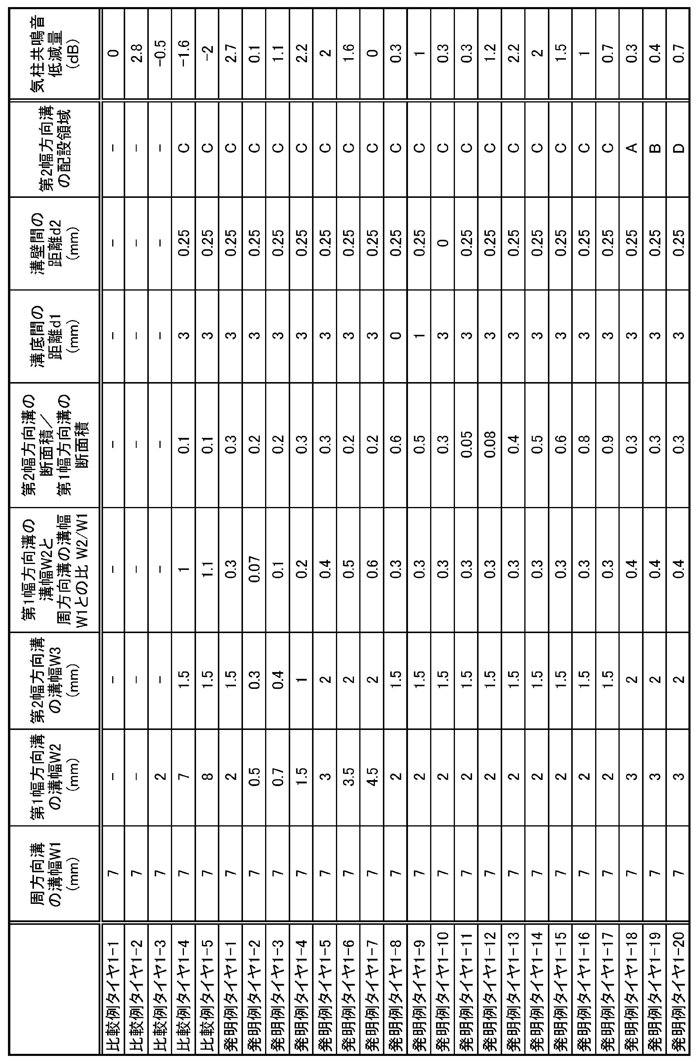
発明例タイヤおよび比較例タイヤ(ともに、タイヤサイズは215/55R17)を表1に示す仕様のもと試作し、気柱共鳴音の低減効果(静粛性)を評価した。
発明例タイヤおよび比較例タイヤ(ともに、タイヤサイズは215/55R17)を表1に示す仕様のもと試作し、気柱共鳴音の低減効果(静粛性)を評価した。
発明例タイヤ1-1~1-20は、図1に示すトレッドパターンを備え、トレッド踏面に4本の周方向溝を有し、該周方向溝のうち、タイヤ幅方向両最外側の周方向溝とトレッド接地端とにより区画されるリブ状陸部(上述の実施形態におけるショルダ陸部5S)に、該陸部を区画する周方向溝とトレッド接地端とを連通する、複数本の第1幅方向溝を備え、該第1幅方向溝内に第2幅方向溝を有しており、周方向溝、第1幅方向溝および第2幅方向溝の、それぞれの溝幅が、「周方向溝1の溝幅>第1幅方向溝の溝幅>第2幅方向溝の溝幅」となっている。
比較例タイヤ1-1は、第1幅方向溝および第2幅方向溝を有しないこと以外は、発明例タイヤ1-1と同様のタイヤである。
比較例タイヤ1-2は、トレッド踏面に4本の周方向溝を有し、該周方向溝により区画される3つのリブ状陸部のうち、タイヤ赤道面を含まない2つのリブ状陸部(上述の実施形態における中間陸部5Mに相当)に、該陸部を区画する両周方向溝を連通する、複数個のヘルムホルツ型の共鳴器を備えている。
比較例タイヤ1-3は、第1幅方向溝内に第2幅方向溝を有しないこと以外は、発明例タイヤ1-1と同様のタイヤである。
比較例タイヤ1-4は、第1幅方向溝の溝幅が周方向溝の溝幅と同じであること以外は、発明例タイヤ1-1と同様のタイヤである。
比較例タイヤ1-5は、第1幅方向溝の溝幅が周方向溝の溝幅より大きいこと以外は、発明例タイヤ1-1と同様のタイヤである。
比較例タイヤ1-4は、第1幅方向溝の溝幅が周方向溝の溝幅と同じであること以外は、発明例タイヤ1-1と同様のタイヤである。
比較例タイヤ1-5は、第1幅方向溝の溝幅が周方向溝の溝幅より大きいこと以外は、発明例タイヤ1-1と同様のタイヤである。
各供試タイヤをリム7.5Jに組み付けてタイヤ車輪とし、空気圧230kPa(相当圧)、タイヤ負荷荷重4.46kNを適用し、時速80km/hにて、室内ドラム試験機上で走行させた際のタイヤ側方音を、JASO C606規格にて定める条件で測定して、1/3オクターブ中心周波数800-1000-1250Hz帯域における、パーシャルオーバーオール値を演算し、気柱共鳴音を算出した。結果は、表1に、比較例タイヤ1-1に対する低減量(dB)を示した。
[試験2]
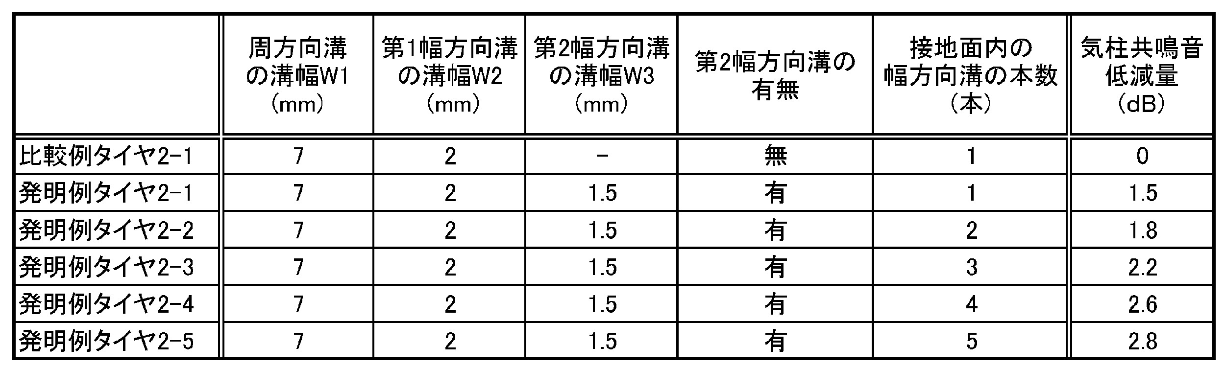
第2幅方向溝を有する第1幅方向溝の配設本数による、気柱共鳴音の低減効果の違いを評価した。
発明例タイヤ2-1は、基本的に図1に示すトレッドパターンを備え、トレッド踏面に4本の周方向溝を有し、該周方向溝のうち、タイヤ幅方向両最外側の周方向溝とトレッド接地端とにより区画されるリブ状陸部(上述の実施形態におけるショルダ陸部5S)に、該陸部を区画する周方向溝とトレッド接地端とを連通する、複数本の第1幅方向溝を備え、該第1幅方向溝内に第2幅方向溝を有しており、周方向溝、第1幅方向溝および第2幅方向溝の、それぞれの溝幅が、「周方向溝1の溝幅>第1幅方向溝の溝幅>第2幅方向溝の溝幅」となっている。タイヤの接地面内に入る、第2幅方向溝を有する第1幅方向溝の本数は、タイヤ幅方向両側の上記リブ状陸部につき、それぞれ1本である。
第2幅方向溝を有する第1幅方向溝の配設本数による、気柱共鳴音の低減効果の違いを評価した。
発明例タイヤ2-1は、基本的に図1に示すトレッドパターンを備え、トレッド踏面に4本の周方向溝を有し、該周方向溝のうち、タイヤ幅方向両最外側の周方向溝とトレッド接地端とにより区画されるリブ状陸部(上述の実施形態におけるショルダ陸部5S)に、該陸部を区画する周方向溝とトレッド接地端とを連通する、複数本の第1幅方向溝を備え、該第1幅方向溝内に第2幅方向溝を有しており、周方向溝、第1幅方向溝および第2幅方向溝の、それぞれの溝幅が、「周方向溝1の溝幅>第1幅方向溝の溝幅>第2幅方向溝の溝幅」となっている。タイヤの接地面内に入る、第2幅方向溝を有する第1幅方向溝の本数は、タイヤ幅方向両側の上記リブ状陸部につき、それぞれ1本である。
比較例タイヤ2-1は、該第1幅方向溝内に第2幅方向溝を有しないこと以外は、発明例タイヤ2-1と同様である。
発明例タイヤ2-2~2-5は、タイヤの接地面内に入る、第2幅方向溝を有する第1幅方向溝の本数が、タイヤ幅方向両側の上記リブ状陸部につき、それぞれ2~5本であること以外は、発明例タイヤ2-1と同様である。
供試タイヤの試験・評価方法は、試験1と同様である。
結果は、表2に、比較例タイヤ2-1に対する低減量(dB)を示した。
結果は、表2に、比較例タイヤ2-1に対する低減量(dB)を示した。
1:周方向溝、 2:第1幅方向溝、 2B:第1幅方向溝の溝底、 2C:第1幅方向溝のタイヤ幅方向内側端とトレッド接地端との中点、 2E:第1幅方向溝のタイヤ幅方向内側端、 2Wa,2Wb:第1幅方向溝の溝壁、 3,43,53,63:第2幅方向溝、 3B,43B,53B,63B:第2幅方向溝の溝底、 3Wa,3Wb,43Wa,43Wb,53Wa,53Wb,63Wa,63Wb:第2幅方向溝の溝壁、 5C:センター陸部、 5M:中間陸部、 5S:ショルダ陸部、 10:タイヤ、 T:トレッド踏面、 TC:タイヤ赤道面、 TE:トレッド接地端、W1:周方向溝の溝幅、 W2:第1幅方向溝の溝幅、 W3第2幅方向溝の溝幅、 X:第2幅方向溝の延在長さ
Claims (6)
- トレッド踏面に、タイヤ周方向に連続して延びる少なくとも1本の周方向溝と、該周方向溝とトレッド接地端とで区画されるショルダ陸部とを有するタイヤであって、
前記ショルダ陸部は、タイヤ幅方向に延び前記周方向溝と前記トレッド接地端とを連通する、第1幅方向溝を有し、
前記第1幅方向溝は、該第1幅方向溝内に、該第1幅方向溝に連通する第2幅方向溝を有し、
前記周方向溝、前記第1幅方向溝及び前記第2幅方向溝の、それぞれの溝幅が、次の関係式を満足することを特徴とするタイヤ。
周方向溝の溝幅>第1幅方向溝の溝幅>第2幅方向溝の溝幅 - 前記第1幅方向溝の溝幅と前記周方向溝の溝幅との比が、0.1以上0.5以下である、請求項1に記載のタイヤ。
- 前記第2幅方向溝の溝底と前記第1幅方向溝の溝底との距離が、1.0mm以上である、請求項1に記載のタイヤ。
- 前記第2幅方向溝の溝壁と前記第1幅方向溝の溝壁との距離が、0.25mm以上である、請求項1又は3に記載のタイヤ。
- 前記第2幅方向溝の前記周方向溝側の端が、前記第1幅方向溝のタイヤ幅方向内側端と前記トレッド接地端との中点よりもタイヤ幅方向外側に位置している、請求項1に記載のタイヤ。
- 前記第2幅方向溝の少なくとも一部が、前記第1幅方向溝のタイヤ幅方向内側端と前記トレッド接地端とのタイヤ幅方向距離を4等分して形成される4つのタイヤ幅方向領域のうち、タイヤ幅方向外側から2番目のタイヤ幅方向領域に位置している、請求項1又は5に記載のタイヤ。
Priority Applications (3)
| Application Number | Priority Date | Filing Date | Title |
|---|---|---|---|
| US16/486,157 US11511568B2 (en) | 2017-03-02 | 2018-03-01 | Tire |
| EP18761141.3A EP3590732B1 (en) | 2017-03-02 | 2018-03-01 | Tire |
| CN201880015208.7A CN110352136B (zh) | 2017-03-02 | 2018-03-01 | 轮胎 |
Applications Claiming Priority (2)
| Application Number | Priority Date | Filing Date | Title |
|---|---|---|---|
| JP2017039585A JP6851859B2 (ja) | 2017-03-02 | 2017-03-02 | タイヤ |
| JP2017-039585 | 2017-03-02 |
Publications (1)
| Publication Number | Publication Date |
|---|---|
| WO2018159782A1 true WO2018159782A1 (ja) | 2018-09-07 |
Family
ID=63371342
Family Applications (1)
| Application Number | Title | Priority Date | Filing Date |
|---|---|---|---|
| PCT/JP2018/007894 Ceased WO2018159782A1 (ja) | 2017-03-02 | 2018-03-01 | タイヤ |
Country Status (5)
| Country | Link |
|---|---|
| US (1) | US11511568B2 (ja) |
| EP (1) | EP3590732B1 (ja) |
| JP (1) | JP6851859B2 (ja) |
| CN (1) | CN110352136B (ja) |
| WO (1) | WO2018159782A1 (ja) |
Families Citing this family (2)
| Publication number | Priority date | Publication date | Assignee | Title |
|---|---|---|---|---|
| JP7680904B2 (ja) * | 2021-08-04 | 2025-05-21 | 株式会社ブリヂストン | タイヤ |
| JP7695181B2 (ja) | 2021-12-13 | 2025-06-18 | 株式会社ブリヂストン | タイヤ |
Citations (9)
| Publication number | Priority date | Publication date | Assignee | Title |
|---|---|---|---|---|
| JPH0853004A (ja) * | 1994-08-12 | 1996-02-27 | Bridgestone Corp | 空気入りタイヤ |
| JPH11198610A (ja) * | 1998-01-19 | 1999-07-27 | Sumitomo Rubber Ind Ltd | 重荷重用タイヤ |
| JP2007001484A (ja) * | 2005-06-24 | 2007-01-11 | Yokohama Rubber Co Ltd:The | 空気入りタイヤ |
| JP2010013091A (ja) * | 2008-06-02 | 2010-01-21 | Yokohama Rubber Co Ltd:The | 空気入りタイヤ |
| JP2011051529A (ja) | 2009-09-03 | 2011-03-17 | Bridgestone Corp | タイヤ |
| JP2011168221A (ja) * | 2010-02-19 | 2011-09-01 | Bridgestone Corp | タイヤ |
| JP2013129427A (ja) * | 2013-04-01 | 2013-07-04 | Sumitomo Rubber Ind Ltd | 空気入りタイヤ |
| JP2013139168A (ja) * | 2011-12-28 | 2013-07-18 | Sumitomo Rubber Ind Ltd | 空気入りタイヤ |
| JP2014166827A (ja) | 2013-02-28 | 2014-09-11 | Bridgestone Corp | 空気入りタイヤ |
Family Cites Families (8)
| Publication number | Priority date | Publication date | Assignee | Title |
|---|---|---|---|---|
| JPS60116510A (ja) | 1983-11-30 | 1985-06-24 | Toyo Tire & Rubber Co Ltd | 低騒音空気入りタイヤ |
| JP3204741B2 (ja) * | 1992-07-06 | 2001-09-04 | オーツタイヤ株式会社 | タイヤのトレッド構造 |
| JPH07172114A (ja) | 1993-12-21 | 1995-07-11 | Bridgestone Corp | 重荷重用空気入りタイヤ |
| DE4403662C2 (de) * | 1994-02-05 | 2001-04-19 | Uniroyal Englebert Gmbh | Fahrzeugreifen |
| DE102010015978B4 (de) * | 2010-03-15 | 2016-09-29 | Waldner Labor- Und Schuleinrichtungen Gmbh Dresden | Tafelanordnung |
| DE102010016978A1 (de) * | 2010-05-18 | 2011-11-24 | Continental Reifen Deutschland Gmbh | Fahrzeugluftreifen |
| JP5432076B2 (ja) * | 2010-07-07 | 2014-03-05 | 東洋ゴム工業株式会社 | 空気入りタイヤ |
| JP5620940B2 (ja) * | 2012-04-17 | 2014-11-05 | 住友ゴム工業株式会社 | 空気入りタイヤ |
-
2017
- 2017-03-02 JP JP2017039585A patent/JP6851859B2/ja active Active
-
2018
- 2018-03-01 CN CN201880015208.7A patent/CN110352136B/zh active Active
- 2018-03-01 WO PCT/JP2018/007894 patent/WO2018159782A1/ja not_active Ceased
- 2018-03-01 US US16/486,157 patent/US11511568B2/en active Active
- 2018-03-01 EP EP18761141.3A patent/EP3590732B1/en active Active
Patent Citations (9)
| Publication number | Priority date | Publication date | Assignee | Title |
|---|---|---|---|---|
| JPH0853004A (ja) * | 1994-08-12 | 1996-02-27 | Bridgestone Corp | 空気入りタイヤ |
| JPH11198610A (ja) * | 1998-01-19 | 1999-07-27 | Sumitomo Rubber Ind Ltd | 重荷重用タイヤ |
| JP2007001484A (ja) * | 2005-06-24 | 2007-01-11 | Yokohama Rubber Co Ltd:The | 空気入りタイヤ |
| JP2010013091A (ja) * | 2008-06-02 | 2010-01-21 | Yokohama Rubber Co Ltd:The | 空気入りタイヤ |
| JP2011051529A (ja) | 2009-09-03 | 2011-03-17 | Bridgestone Corp | タイヤ |
| JP2011168221A (ja) * | 2010-02-19 | 2011-09-01 | Bridgestone Corp | タイヤ |
| JP2013139168A (ja) * | 2011-12-28 | 2013-07-18 | Sumitomo Rubber Ind Ltd | 空気入りタイヤ |
| JP2014166827A (ja) | 2013-02-28 | 2014-09-11 | Bridgestone Corp | 空気入りタイヤ |
| JP2013129427A (ja) * | 2013-04-01 | 2013-07-04 | Sumitomo Rubber Ind Ltd | 空気入りタイヤ |
Non-Patent Citations (1)
| Title |
|---|
| See also references of EP3590732A4 |
Also Published As
| Publication number | Publication date |
|---|---|
| JP6851859B2 (ja) | 2021-03-31 |
| JP2018144553A (ja) | 2018-09-20 |
| EP3590732B1 (en) | 2020-11-11 |
| EP3590732A4 (en) | 2020-01-08 |
| CN110352136B (zh) | 2022-04-01 |
| EP3590732A1 (en) | 2020-01-08 |
| CN110352136A (zh) | 2019-10-18 |
| US11511568B2 (en) | 2022-11-29 |
| US20190375247A1 (en) | 2019-12-12 |
Similar Documents
| Publication | Publication Date | Title |
|---|---|---|
| US10377184B2 (en) | Pneumatic tire | |
| US9302553B2 (en) | Pneumatic tire | |
| EP1372988B1 (en) | Tread pattern for car tire | |
| EP0680837B1 (en) | Pneumatic tyre | |
| US9738120B2 (en) | Pneumatic tire | |
| JP6762267B2 (ja) | タイヤ | |
| JP6887908B2 (ja) | タイヤ | |
| JP7108633B2 (ja) | 空気入りタイヤ | |
| JP6450224B2 (ja) | 空気入りタイヤ | |
| WO2014174813A1 (ja) | 空気入りタイヤ | |
| US20140311638A1 (en) | Pneumatic tire | |
| JP4402393B2 (ja) | 空気入りタイヤ | |
| JP6851858B2 (ja) | タイヤ | |
| JP6851859B2 (ja) | タイヤ | |
| WO2016143477A1 (ja) | 空気入りタイヤ | |
| CN114829163B (zh) | 轮胎 | |
| JP7108632B2 (ja) | 空気入りタイヤ | |
| JP7074586B2 (ja) | 空気入りタイヤ | |
| JP7057234B2 (ja) | タイヤ | |
| WO2020179169A1 (ja) | 空気入りタイヤ |
Legal Events
| Date | Code | Title | Description |
|---|---|---|---|
| 121 | Ep: the epo has been informed by wipo that ep was designated in this application |
Ref document number: 18761141 Country of ref document: EP Kind code of ref document: A1 |
|
| NENP | Non-entry into the national phase |
Ref country code: DE |
|
| ENP | Entry into the national phase |
Ref document number: 2018761141 Country of ref document: EP Effective date: 20191002 |