WO2018164162A1 - 回転伝達機構、及び回転伝達機構を備えた自転車 - Google Patents
回転伝達機構、及び回転伝達機構を備えた自転車 Download PDFInfo
- Publication number
- WO2018164162A1 WO2018164162A1 PCT/JP2018/008687 JP2018008687W WO2018164162A1 WO 2018164162 A1 WO2018164162 A1 WO 2018164162A1 JP 2018008687 W JP2018008687 W JP 2018008687W WO 2018164162 A1 WO2018164162 A1 WO 2018164162A1
- Authority
- WO
- WIPO (PCT)
- Prior art keywords
- outer peripheral
- rotation
- peripheral convex
- internal
- transmission mechanism
- Prior art date
- Legal status (The legal status is an assumption and is not a legal conclusion. Google has not performed a legal analysis and makes no representation as to the accuracy of the status listed.)
- Ceased
Links
Images












Classifications
-
- B—PERFORMING OPERATIONS; TRANSPORTING
- B62—LAND VEHICLES FOR TRAVELLING OTHERWISE THAN ON RAILS
- B62M—RIDER PROPULSION OF WHEELED VEHICLES OR SLEDGES; POWERED PROPULSION OF SLEDGES OR SINGLE-TRACK CYCLES; TRANSMISSIONS SPECIALLY ADAPTED FOR SUCH VEHICLES
- B62M1/00—Rider propulsion of wheeled vehicles
- B62M1/10—Rider propulsion of wheeled vehicles involving devices which enable the mechanical storing and releasing of energy occasionally, e.g. arrangement of flywheels
- B62M1/105—Rider propulsion of wheeled vehicles involving devices which enable the mechanical storing and releasing of energy occasionally, e.g. arrangement of flywheels using elastic elements
-
- B—PERFORMING OPERATIONS; TRANSPORTING
- B62—LAND VEHICLES FOR TRAVELLING OTHERWISE THAN ON RAILS
- B62M—RIDER PROPULSION OF WHEELED VEHICLES OR SLEDGES; POWERED PROPULSION OF SLEDGES OR SINGLE-TRACK CYCLES; TRANSMISSIONS SPECIALLY ADAPTED FOR SUCH VEHICLES
- B62M1/00—Rider propulsion of wheeled vehicles
- B62M1/10—Rider propulsion of wheeled vehicles involving devices which enable the mechanical storing and releasing of energy occasionally, e.g. arrangement of flywheels
-
- B—PERFORMING OPERATIONS; TRANSPORTING
- B62—LAND VEHICLES FOR TRAVELLING OTHERWISE THAN ON RAILS
- B62M—RIDER PROPULSION OF WHEELED VEHICLES OR SLEDGES; POWERED PROPULSION OF SLEDGES OR SINGLE-TRACK CYCLES; TRANSMISSIONS SPECIALLY ADAPTED FOR SUCH VEHICLES
- B62M11/00—Transmissions characterised by the use of interengaging toothed wheels or frictionally-engaging wheels
- B62M11/02—Transmissions characterised by the use of interengaging toothed wheels or frictionally-engaging wheels of unchangeable ratio
-
- B—PERFORMING OPERATIONS; TRANSPORTING
- B62—LAND VEHICLES FOR TRAVELLING OTHERWISE THAN ON RAILS
- B62M—RIDER PROPULSION OF WHEELED VEHICLES OR SLEDGES; POWERED PROPULSION OF SLEDGES OR SINGLE-TRACK CYCLES; TRANSMISSIONS SPECIALLY ADAPTED FOR SUCH VEHICLES
- B62M21/00—Transmissions characterised by use of resilient elements therein
-
- B—PERFORMING OPERATIONS; TRANSPORTING
- B62—LAND VEHICLES FOR TRAVELLING OTHERWISE THAN ON RAILS
- B62M—RIDER PROPULSION OF WHEELED VEHICLES OR SLEDGES; POWERED PROPULSION OF SLEDGES OR SINGLE-TRACK CYCLES; TRANSMISSIONS SPECIALLY ADAPTED FOR SUCH VEHICLES
- B62M3/00—Construction of cranks operated by hand or foot
-
- F—MECHANICAL ENGINEERING; LIGHTING; HEATING; WEAPONS; BLASTING
- F16—ENGINEERING ELEMENTS AND UNITS; GENERAL MEASURES FOR PRODUCING AND MAINTAINING EFFECTIVE FUNCTIONING OF MACHINES OR INSTALLATIONS; THERMAL INSULATION IN GENERAL
- F16F—SPRINGS; SHOCK-ABSORBERS; MEANS FOR DAMPING VIBRATION
- F16F15/00—Suppression of vibrations in systems; Means or arrangements for avoiding or reducing out-of-balance forces, e.g. due to motion
- F16F15/10—Suppression of vibrations in rotating systems by making use of members moving with the system
- F16F15/12—Suppression of vibrations in rotating systems by making use of members moving with the system using elastic members or friction-damping members, e.g. between a rotating shaft and a gyratory mass mounted thereon
-
- F—MECHANICAL ENGINEERING; LIGHTING; HEATING; WEAPONS; BLASTING
- F16—ENGINEERING ELEMENTS AND UNITS; GENERAL MEASURES FOR PRODUCING AND MAINTAINING EFFECTIVE FUNCTIONING OF MACHINES OR INSTALLATIONS; THERMAL INSULATION IN GENERAL
- F16F—SPRINGS; SHOCK-ABSORBERS; MEANS FOR DAMPING VIBRATION
- F16F15/00—Suppression of vibrations in systems; Means or arrangements for avoiding or reducing out-of-balance forces, e.g. due to motion
- F16F15/10—Suppression of vibrations in rotating systems by making use of members moving with the system
- F16F15/12—Suppression of vibrations in rotating systems by making use of members moving with the system using elastic members or friction-damping members, e.g. between a rotating shaft and a gyratory mass mounted thereon
- F16F15/121—Suppression of vibrations in rotating systems by making use of members moving with the system using elastic members or friction-damping members, e.g. between a rotating shaft and a gyratory mass mounted thereon using springs as elastic members, e.g. metallic springs
- F16F15/124—Elastomeric springs
-
- F—MECHANICAL ENGINEERING; LIGHTING; HEATING; WEAPONS; BLASTING
- F16—ENGINEERING ELEMENTS AND UNITS; GENERAL MEASURES FOR PRODUCING AND MAINTAINING EFFECTIVE FUNCTIONING OF MACHINES OR INSTALLATIONS; THERMAL INSULATION IN GENERAL
- F16H—GEARING
- F16H55/00—Elements with teeth or friction surfaces for conveying motion; Worms, pulleys or sheaves for gearing mechanisms
- F16H55/02—Toothed members; Worms
- F16H55/30—Chain-wheels
Definitions
- the present invention relates to a rotation transmission mechanism, and more particularly to a rotation transmission mechanism used by being mounted on a rotation shaft such as a crankshaft of a bicycle.
- a rotation transmission mechanism used by being mounted on a rotation shaft such as a crankshaft of a bicycle.
- the bicycle can run with a small force once the bicycle starts running.
- the driver receives a particularly large repulsive force from the bicycle, and a part of the input energy bounces back to the knees, ankles, hips, etc.
- the input energy could not be used efficiently, leading to a reduction in propulsion.
- the load (drag) on the human body becomes particularly large. The necessary energy was also increased.
- a bicycle rotation having an internal rotation member having a rotation shaft and an external rotation member rotatably disposed on the rotation shaft of the internal rotation member”.
- a bicycle equipped with a pedal is proposed (see Patent Document 1).
- the internal rotation member has one or more outer peripheral protrusions that are formed integrally with the rotation shaft or fixed to the outer periphery of the rotation shaft and project to the outer periphery side of the rotation shaft
- the external rotating member is a side plate portion rotatably inserted into the rotating shaft at a side position of the outer peripheral convex portion of the inner rotating member, and the outer rotating member is rotated outside the outer peripheral convex portion of the inner rotating member.
- An outer cylinder portion standing on the outer periphery of the side plate portion concentrically with the shaft, and formed integrally with the side plate portion and / or the outer cylinder portion so as to protrude toward the inner peripheral side of the outer cylinder portion, or One or more inner peripheral convex portions fixed to the side plate portion and / or the outer cylindrical portion and arranged alternately with the outer peripheral convex portions of the inner rotating member, and the side plate portion or the outer cylinder of the outer rotating member
- the chain ring is formed or fixed on the part, before the outer peripheral convex part
- An elastic deformation portion is disposed between the outer circumferential convex portion and the inner circumferential convex portion on the rotational direction side, and when the inner rotating member and the outer rotating member rotate relatively, the elastic deforming portion is And elastically deformed by being sandwiched between the inner peripheral convex portion.
- the bicycle rotation transmission mechanism By arranging a bicycle rotation transmission mechanism on the rotating shaft of a bicycle that travels by rotating wheels by human power, the bicycle rotation transmission mechanism can be externally applied during initial movements such as starting, acceleration, and climbing or during traveling. It can absorb and store shock energy and excessive input energy generated by the large load received from the power source, greatly reducing the load on the human body.
- the rotation transmission mechanism for bicycles can effectively use the stored energy when the input energy is reduced or is interrupted for the rotation of the rotating shaft without waste. It is excellent and can be reduced in weight with a simple configuration with a small number of parts.
- the rotation transmission mechanism for bicycles is easy to disassemble and assemble, has excellent maintainability and productivity, can be easily incorporated into existing bicycles, and excels in mass productivity, assembly workability, space saving, and versatility. .
- By providing such a bicycle rotation transmission mechanism it is possible to reduce the load on the user's legs and the like.
- the bicycle rotation transmission mechanism has excellent acceleration performance, uniformity of rotational torque, stability during low-speed driving, and is complicated. No operation is required, and the load on the driver's knees and ankles can be reduced.
- a bicycle equipped with a bicycle rotation transmission mechanism can be easily driven.
- bicycles as daily commodities that can be easily traveled on slopes and roads with high resistance, they are also excellent in acceleration performance, uniformity of rotational torque, and stability during low-speed driving, for rehabilitation and competition purposes.
- a bicycle that can be used and has excellent operational stability, handleability, and versatility can be provided.
- An object of the present invention is to provide a rotation transmission mechanism capable of realizing a bicycle having better usability than before and a bicycle including the same.
- a rotation transmission mechanism includes an internal rotation member through which a rotation shaft is inserted, and an external rotation member that is rotatably disposed with respect to the internal rotation member.
- the internal rotation member includes a disc-shaped internal rotation member main body having a rotation shaft insertion hole, and is integrally formed with the internal rotation member main body or fixed to the internal rotation member main body and protrudes to an outer peripheral side of the internal rotation member main body.
- the external rotating member protrudes to an inner peripheral side of the annular portion, and an annular portion that is rotatably arranged with respect to the inner rotating member outside the outer peripheral convex portion of the inner rotating member. And one or a plurality of inner peripheral convex portions that are integrally formed with the annular portion or fixed to the annular portion and arranged alternately with the outer peripheral convex portions of the internal rotation member.
- the outer peripheral convex portion has an advancing surface located at a position shifted from the center of the outer peripheral convex portion along the forward rotation direction in which the rotation transmission mechanism rotates by advancing.
- An elastic deformation portion is disposed between the advance surface and the inner peripheral convex portion facing the advance surface in the forward rotation direction.
- the elastic deformation portion is sandwiched between the outer peripheral convex portion and the inner peripheral convex portion and elastically deforms.
- the outer peripheral convex portion and the annular portion are provided with a guide portion that guides the outer peripheral convex portion so as to be slidable along the rotation direction of the rotation transmission mechanism with respect to the annular portion. .
- the outer peripheral convex portion of the inner rotating member and the inner peripheral convex portion of the outer rotating member on the rotational direction side of the outer peripheral convex portion when the bicycle moves forward that is, the outer peripheral convex portion advances.
- An elastic deformation portion is disposed between the surface and the inner peripheral convex portion facing the advance surface in the advance rotation direction.
- the elastically deforming portion is sandwiched between the outer peripheral convex portion and the inner peripheral convex portion and elastically deforms.
- the outer peripheral convex portion of the inner rotating member and the outer rotating member of the outer rotating member are arranged along the rotation direction with respect to the annular portion.
- a guide portion for guiding the slidable movement is provided.
- another member for rotating the internal rotation member in the same direction as the external rotation member for example, a side plate portion for slidably holding the internal rotation member inside the annular portion of the external rotation member Or the cover part
- a rotation transmission mechanism capable of realizing a bicycle and the like that are more usable than conventional ones.
- the guide portion is formed on each of two opposing surfaces of the outer peripheral convex portion and the annular portion.
- a groove may be formed on one of the two surfaces of the outer peripheral convex portion and the annular portion. In this case, a projection to be inserted into the groove is formed on the other surface.
- the groove is formed on one surface of the two surfaces facing each other of the outer peripheral convex portion and the annular portion, and the protrusion inserted into the groove is provided on the other surface.
- the external rotation member includes a first external member, a second external member fixed to overlap the first external member, the first external member, and the A groove serving as the guide portion formed between the second external member and the second external member.
- the internal rotation member is disposed between the first external member and the second external member, and has a projection that is the guide portion positioned at the tip of the outer peripheral convex portion. The protrusion may be inserted into the groove.
- the external rotation member includes a protrusion that is the guide portion provided in the annular portion.
- the internal rotation member includes a first internal member having a first protrusion, a second internal member fixed to overlap the first internal member and having a second protrusion, the first protrusion, and the first protrusion And a groove that is the guide portion formed between the two protruding portions. The protrusion may be inserted into the groove.
- the bicycle according to the second aspect of the present invention includes the rotation transmission mechanism according to the first aspect.
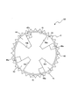
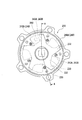
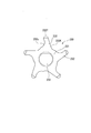
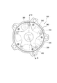
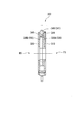
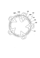
- FIG. 3 is a sectional view taken along line III-III shown in FIG. It is a top view which shows the surface of the external rotation member which comprises the rotation transmission mechanism in Embodiment 1 of this invention. It is a top view which shows the surface of the internal rotation member which comprises the rotation transmission mechanism in Embodiment 1 of this invention. It is a top view which shows the surface of the cover part which comprises the rotation transmission mechanism in Embodiment 1 of this invention.
- FIG. 10 is a sectional view taken along line IV-IV shown in FIG. 9. It is a top view which shows the surface of the internal rotation member which comprises the rotation transmission mechanism in Embodiment 2 of this invention. It is a top view which shows the surface of the external rotation member which comprises the said rotation transmission mechanism in Embodiment 2 of this invention. It is a figure explaining the structure of the modification of the internal rotation member shown in FIG.
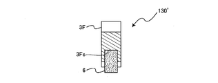
- FIG. 14 is a diagram for explaining a configuration of a modified example of the internal rotation member shown in FIG. 11, and a cross-sectional view taken along line VV shown in FIG. 13A. It is a top view which shows the modification of the external rotation member shown in FIG. It is sectional drawing which shows the modification of the rotation transmission mechanism shown in FIG. It is a top view which shows the back surface of the rotation transmission mechanism in Embodiment 3 of this invention. It is sectional drawing which follows the AA line shown in FIG. It is a top view which shows the 1st external member which comprises the rotation transmission mechanism in Embodiment 3 of this invention.
- FIG. 22 is a sectional view taken along line BB shown in FIG. 21. It is a top view which shows the external rotation member which comprises the rotation transmission mechanism in Embodiment 4 of this invention. It is a top view which shows the internal rotation member which comprises the rotation transmission mechanism in Embodiment 4 of this invention. It is sectional drawing which shows the internal rotation member which comprises the rotation transmission mechanism in Embodiment 4 of this invention.
- Embodiment 1 (Configuration of rotation transmission mechanism) First, the configuration of the rotation transmission mechanism according to Embodiment 1 of the present invention will be described with reference to FIGS. 1 to 6B.
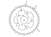
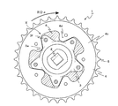
- FIG. 1 is a plan view showing the surface of the rotation transmission mechanism according to Embodiment 1 of the present invention.
- FIG. 2 is a plan view showing the back surface of the rotation transmission mechanism.
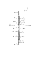
- 3 is a cross-sectional view taken along line III-III shown in FIG.
- FIG. 4A is a plan view showing a surface of an external rotation member constituting the rotation transmission mechanism.
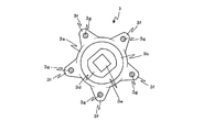
- FIG. 4B is a plan view showing the surface of the internal rotation member constituting the rotation transmission mechanism.
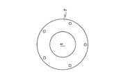
- FIG. 4C is a plan view showing the surface of the cover portion constituting the rotation transmission mechanism.
- FIG. 5 is a plan view showing the back surface of the internal rotation member constituting the rotation transmission mechanism.
- FIG. 1 is a plan view showing the surface of the rotation transmission mechanism according to Embodiment 1 of the present invention.
- FIG. 2 is a plan view showing the back surface of the rotation transmission mechanism.
- 3 is a cross-sectional view taken along line III-III shown in FIG.
- FIG. 4A is a plan
- FIG. 6A is a diagram illustrating the rotation transmission mechanism, and is a plan view illustrating a state where a cover portion is removed.
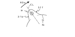
- FIG. 6B is an enlarged plan view in which a portion indicated by a symbol X in FIG. 6A is enlarged.
- symbol FS indicates the surface of the rotation transmission mechanism
- symbol BS indicates the back surface of the rotation transmission mechanism. That is, the plan view indicated by the symbol FS corresponds to FIG. 1, and the plan view indicated by the symbol BS corresponds to FIG.
- the rotation transmission mechanism 1 includes, for example, an internal rotation member 3 through which a rotation shaft such as a crankshaft of a bicycle is inserted, and rotation with respect to the internal rotation member 3
- An external rotating member 4 that is freely arranged and an elastic deformation portion 6 (elastic deformation body) are provided.
- the internal rotation member 3 includes a disk-shaped internal rotation member main body 3a, a columnar convex portion 3b integrally formed on the surface of the internal rotation member main body 3a, and a columnar shape integrally formed on the back surface of the internal rotation member main body 3a. 3c, a press-fitting recess 3d formed in the protrusion 3b, a rectangular cylindrical crankshaft insertion hole 3e (rotating shaft) that penetrates the protrusion 3c and the inner rotary member main body 3a and reaches the press-fit recess 3d. Insertion hole). As shown in FIG.
- the height of the convex portion 3b protruding from the surface of the internal rotary member main body 3a (the distance from the surface of the internal rotary member main body 3a to the end surface of the convex portion 3b in the direction of the crankshaft) is described later. It is larger than the thickness of the cover part 4c. Further, the height of the convex portion 3c protruding from the back surface of the internal rotating member main body 3a (the distance from the back surface of the internal rotating member main body 3a to the end surface of the convex portion 3c in the direction of the crankshaft) is as follows. Greater than thickness.
- the press-fit recess 3d has a substantially oval shape as shown in FIG.
- the internal rotating member 3 includes five outer peripheral convex portions 3f that are integrally formed with the internal rotating member main body 3a and project outward from the outer peripheral portion of the internal rotating member main body 3a.
- Bearing balls 3g and 3h are rotatably held on the front and back surfaces of the outer peripheral projection 3f, respectively.
- the balls 3g and 3h are 45 to 65%, preferably 58 to 62%, of the protrusion amount (length) of the outer peripheral protrusion 3f. In the position.
- each of the plurality of outer peripheral convex portions 3f has an advance surface 3ff and an opposite surface 3fb located on the opposite side of the advance surface 3ff.
- a position shifted from the center line CL of the outer circumferential convex portion 3f in the radial direction of the internal rotation member 3 along the rotation direction RDa forward rotation direction, rotation direction of the rotation transmission mechanism 1 when the bicycle moves forward
- the advance surface 3ff is positioned at the right side of the outer peripheral convex portion 3f in FIG. 6B.
- the position shifted from the center line CL of the outer circumferential convex portion 3f in the radial direction of the inner rotating member 3 along the direction opposite to the rotational direction RDa that is, the position on the left side of the outer circumferential convex portion 3f in FIG.
- the surface 3fb is located.
- the external rotating member 4 includes a side plate portion 4a, an annular portion 4b, and a cover portion 4c.
- the side plate portion 4 a is located next to the outer peripheral convex portion 3 f of the internal rotation member 3 and is rotatable with respect to the convex portion 3 c of the internal rotation member 3.
- An insertion hole 4e is formed in the side plate portion 4a, and a convex portion 3c is inserted in the insertion hole 4e.
- the annular portion 4b is screwed and fixed to the outer periphery of the side plate portion 4a outside the outer peripheral convex portion 3f of the internal rotating member 3.
- the cover part 4c is rotatable with respect to the convex part 3b in a state of being disposed opposite to the side plate part 4a.
- An insertion hole 4f is formed in the cover part 4c, and a convex part 3b is inserted in the insertion hole 4f.
- the cover portion 4c is fixed to the annular portion 4b with screws.
- the internal rotation member 3 rotates while the bearing balls 3g and 3h held on the front and back surfaces of the outer peripheral projection 3f roll on the cover 4c and the side plate 4a, respectively. Thereby, the internal rotation member 3 can be smoothly rotated.
- the external rotating member 4 includes five inner peripheral convex portions 4d.
- inner peripheral parts 4 d of inner peripheral parts are integrally formed in the annular part 4b so that it may protrude toward the inner peripheral side of the annular part 4b, and are arrange
- one outer peripheral convex portion 3f is disposed between the inner peripheral convex portions 4d adjacent to each other, and one inner peripheral convex portion 4d is disposed between the outer peripheral convex portions 3f adjacent to each other.
- a plurality of inner peripheral convex portions 4d and a plurality of outer peripheral convex portions 3f are disposed so as to be disposed.
- a chain ring 5 is fixed to the outer peripheral portion on the back surface side of the annular portion 4 b of the external rotating member 4.
- the elastic deformation part 6 is comprised by elastic members, such as a synthetic rubber, and can be elastically deformed.
- the elastic deformation portion 6 is sandwiched between the cover portion 4c and the side plate portion 4a, and is surrounded by the annular portion 4b.
- each of the elastically deforming portions 6 is sandwiched between the forward surface 3ff of the outer peripheral convex portion 3f and the inner peripheral convex portion 4d facing the forward surface 3ff in the rotational direction RDa.
- the number of the elastically deformable portions 6 shown in FIGS. 6A and 8 is five, the number of the elastically deformable portions 6 is not limited.
- the elastic deformation portion 6 transmits a rotational force from the external rotation member 4 to the internal rotation member 3 while elastically deforming. Further, the elastic deformation portion 6 transmits the energy stored in the elastic deformation portion 6 to the internal rotation member 3 as a rotational force.
- Rotation transmission mechanism 1 is assembled in the following procedure. That is, first, as shown in FIGS. 2 and 3, the side plate portion 4a is screwed and fixed to the annular portion 4b from the back side of the annular portion 4b. Next, as shown in FIGS. 3, 4A to 4C, and 6A, the side plate portion 4a is arranged such that the convex portion 3c located on the back surface side of the internal rotation member 3 is directed from the front surface side FS of the side plate portion 4a toward the back surface side BS. The insertion hole 4e is inserted. Thereby, the internal rotation member 3 is arrange
- the convex portion 3b located on the surface side of the internal rotation member 3 is inserted into the insertion hole 4f of the cover portion 4c, and the cover portion 4c is inserted into the annular shape. Screw on the surface of the part 4b.
- an elastic deformation portion 6 made of synthetic rubber is disposed between the advance surface 3ff of the outer peripheral convex portion 3f and the inner peripheral convex portion 4d.
- the outer peripheral convex portion 3f and the inner peripheral convex portion 4d located at a position along the rotational direction from the outer peripheral convex portion 3f when the bicycle moves forward (when the rotation transmission mechanism 1 rotates along the rotational direction RDa).
- the elastic deformation part 6 is arrange
- the elastic deformation portion 6 When the inner rotating member 3 and the outer rotating member 4 are relatively rotated, the elastic deformation portion 6 is sandwiched between the outer peripheral convex portion 3f and the inner peripheral convex portion 4d and elastically deformed (compressed). Yes.
- the lateral deformation of the elastic deformation portion 6, that is, the deformation of the elastic deformation portion 6 in the axial direction of the rotation transmission mechanism 1 in FIG. 3 is prevented by the side plate portion 4 a and the cover portion 4 c, thereby When the driver steps on the pedal, a part of the energy input to the rotation transmission mechanism 1 can be efficiently stored in the elastic deformation portion 6.
- the surface of the outer circumferential convex portion 3f that faces in the rotation direction is the surface that faces in the opposite direction to the rotation direction (opposite surface).
- 3fb which is about 10 to 15% wider, preferably about 12 to 13% wider than the area of the surface deviating from the center line CL along the direction opposite to the rotational direction RDa. For this reason, it arrange
- the formed elastically deformable portion 6 can be compressed and deformed in a wider area (range) than before, and compression (elastic) energy can be efficiently stored in the elastically deformable portion 6.
- This compression (elastic) energy is converted into rotational energy and used as a driving force for a bicycle or the like.
- the outer peripheral convex portion 3f is formed such that the advancing surface 3ff (surface facing in the rotation direction) has a gentler inclination than the opposite surface 3fb (surface facing in the direction opposite to the rotation direction).
- a curved surface that continuously connects the advance surface 3ff and the outer peripheral surface of the internal rotation member body 3a is formed at the boundary between the advance surface 3ff (the surface facing the rotation direction) and the internal rotation member body 3a.
- the area of the advancing surface 3ff (surface facing the rotation direction) of the outer peripheral convex portion 3f is increased, so that the height of the outer peripheral convex portion 3f (from the outer peripheral surface of the inner rotating member main body 3a to the outer periphery).
- the distance to the outer end of the convex portion 3f can be reduced, and the rotation transmission mechanism 1 can be reduced in size.
- the length (distance) of the outer peripheral convex part 3f (advance surface 3ff) that compresses the elastic deformation part 6 increases from the outer peripheral surface of the inner rotating member main body 3a toward the outer end of the outer peripheral convex part 3f, more Can be stored.
- the centrifugal force at the time of rotation of the rotation transmission mechanism 1 can be adjusted by adjusting the thickness of the annular part 4b, the inertia force of rotation can be adjusted.
- the surface facing the forward surface 3ff (the surface facing the rotation direction) of the outer circumferential convex portion 3f is formed in a recessed state. For this reason, it arrange
- the volume of the inner space of the recess formed by the recess is preferably 2 to 5% with respect to the volume of the elastically deformable portion 6. This is because if the dent is too large, compression of the elastically deformable portion 6 becomes insufficient.
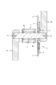
- FIG. 7 is a view showing an example in which the rotation transmission mechanism according to Embodiment 1 of the present invention is used in a bicycle, and is a cross-sectional view showing a main part of the rotation transmission mechanism.
- FIG. 8 is a view showing the rotation transmission mechanism, and is a plan view showing a state in which the cover 4c is removed and the elastically deforming portion is elastically deformed (compressed).
- crankshaft 2 of a bicycle as a rotating shaft is rotatably held by a crankshaft holding portion 7 integrated with a bicycle frame via left and right ball bearings 8a and 8b.
- the right end portion of the crankshaft 2 is inserted into and fixed to the crankshaft insertion hole 3e (see FIG. 3) of the internal rotation member 3, whereby the rotation transmission mechanism 1 is mounted on the crankshaft 2.
- Crank arms 9a and 9b are fixed to the left and right ends of the crankshaft 2 with a phase difference of 180 degrees.
- reference numeral 10 is a crank arm fixing member for fixing the crank arms 9 a and 9 b to the crankshaft 2.
- the crankshaft 2 is fitted with a square tube of the crankshaft insertion hole 3e of the internal rotation member 3, and both rotate integrally.
- a rotatable pedal (not shown) is disposed at the end of the crank arms 9a and 9b.
- the elastic deformation portion 6 is elastically deformed. After the elastic deformation portion 6 is deformed, the rotational force of the crankshaft 2 is changed from the outer peripheral convex portion 3f to the inner peripheral convex portion 4d. As a result, the crankshaft 2 to the chain ring 5 rotate substantially integrally. The rotational force is reliably transmitted to a sprocket provided on the rear wheel side of the bicycle through a chain (not shown) stretched on the chain ring 5.
- the elastically deformable portion 6 that has been elastically deformed (compressed) is restored when the input of energy from the pedal to the rotation transmission mechanism 1 is interrupted or weakened, and presses the inner peripheral convex portion 4d as the restored energy, thereby causing the external rotating member 4 to be restored. Then, the chain ring 5 is rotated in the traveling direction. That is, the compression (elastic) energy of the elastic deformation portion 6 is converted into rotational energy and used as a propulsive force for the bicycle.
- the case where five outer peripheral convex portions 3f and five inner peripheral convex portions 4d are provided has been described as an example, but the present invention is not necessarily limited to such a configuration.
- the number of the outer peripheral convex portions 3f and the number of the inner peripheral convex portions 4d may be one or more, respectively.
- the number of the outer peripheral convex portions 3f and The number of inner peripheral convex portions 4d is preferably four or more.
- the number of the outer peripheral convex part 3f and the inner peripheral convex part 4d is eight or less.
- the outer peripheral convex part 3f was integrally formed in the internal rotation member main body 3a was mentioned as an example, it demonstrated and this invention is not necessarily limited to such a structure.
- the outer peripheral convex portion may be fixed to the internal rotary member main body.
- the case where the inner peripheral convex portion 4d is integrally formed with the annular portion 4b has been described as an example, but the present invention is not necessarily limited to such a configuration.
- the inner peripheral convex portion may be fixed to the annular portion.
- the elastic deformation portion 6 is made of synthetic rubber
- the elastic deformation portion only needs to be elastically deformed (compressive deformation) when the internal rotation member 3 and the external rotation member 4 are relatively rotated and can transmit rotation between the internal rotation member 3 and the external rotation member 4 after the deformation.
- the shape, size, deformation amount, elastic modulus, and the like of the elastically deformable portion can be appropriately selected according to the user's preference.
- a gas sealed between the outer peripheral convex portion 3f and the inner peripheral convex portion 4d can be used as the elastic deformation portion.
- FIG. 9 is a plan view showing the surface of the rotation transmission mechanism according to the second embodiment of the present invention.
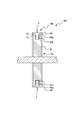
- 10 is a cross-sectional view taken along the line IV-IV shown in FIG.
- FIG. 11 is a plan view showing the surface of the internal rotation member constituting the rotation transmission mechanism.
- FIG. 12 is a plan view showing the surface of the external rotation member constituting the rotation transmission mechanism.
- the rotation transmission mechanism 100 according to the second embodiment is different from the first embodiment in that the inner rotation member 130 and the outer rotation member 140 are engaged by the guide portion 150 without providing a cover portion or the like. Different.
- the rotation transmission mechanism 100 includes, for example, an internal rotation member 130 through which a rotation shaft such as a crankshaft of a bicycle is inserted, and an external rotation member 140 that is rotatably disposed with respect to the internal rotation member 130. And an elastically deformable portion 6.
- the internal rotation member 130 is integrated with the disk-shaped internal rotation member main body 3a, the substantially rectangular cylindrical crankshaft insertion hole 3e penetrating the internal rotation member main body 3a, and the internal rotation member main body 3a.
- Four outer peripheral convex portions 3F that are formed and project outward from the outer peripheral portion of the inner rotating member main body 3a are provided.
- the outer peripheral convex portion 3F is formed in a substantially fan shape whose width increases as the distance from the inner rotating member main body 3a increases. As shown in FIG. 9, the outer peripheral convex portion 3F has an inner side elastic deformation portion abutting surface 3Fa facing an outer side elastic deformation portion abutting surface 4da of an inner peripheral convex portion 4d of the outer rotation member 140 described later.
- the elastic deformation portion 6 is attached to the inner elastic deformation portion contact surface 3Fa.
- the inner elastic deformation portion contact surface 3Fa extends in a linear shape in the radial direction from the center of the inner rotating member main body 3a.
- the present embodiment is not limited to such a structure, and a curved portion that holds a part of the elastic deformation portion 6 may be provided on the inner elastic deformation portion contact surface 3Fa. Further, a holding portion for holding the elastic deformation portion 6 may be formed on the inner elastic deformation portion contact surface 3Fa.
- the outer peripheral convex portion 3F has an end surface 3t (an end surface 3t forming the outer edge of the outer peripheral convex portion 3F) facing the inner peripheral end surface 4t of the external rotating member 140 (see FIGS. 9 and 12).
- a groove 3Fb carved in the direction of the internal rotation member main body 3a is formed in the end surface 3t at the approximate center in the thickness direction (left and right direction in FIG. 10) of the outer peripheral convex portion 3F.
- the groove 3Fb is formed in an arc shape along the inner periphery of the external rotating member 140 (see FIG. 9).
- FIG. 13A and 13B are diagrams illustrating a configuration of a modified example of the internal rotation member illustrated in FIG. 11.
- FIG. 13A is a plan view showing the surface of the internal rotation member.
- 13B is a cross-sectional view taken along line VV shown in FIG. 13A.
- the internal rotation member 130 ′ has an outer peripheral convex portion 3F in which a notch is formed in the internal elastic deformation portion contact surface 3Fa. That is, the notch portion 3Fc formed in a semicircular shape when viewed from the surface of the internal rotation member 130 ′ (in plan view) is formed in the internal elastic deformation portion contact surface 3Fa.
- the elastic deformation portion 6 is formed in a cylindrical shape that is formed in a circular shape when viewed from the surface of the internal rotation member 130 ′ (in plan view). A part of the elastic deformation part 6 is inserted into the notch 3Fc, and the other part of the elastic deformation part 6 protrudes from the inner elastic deformation part contact surface 3Fa.
- the elastic deformable portion 6 can transmit rotation by using the rotation transmitting mechanism 100, for example. It is possible to prevent the mechanism 100 from being detached.
- the external rotating member 140 includes an annular portion 4B and four inner peripheral convex portions 4d.
- the annular portion 4 ⁇ / b> B is disposed so as to be rotatable with respect to the internal rotation member 130 outside the outer peripheral convex portion 3 ⁇ / b> F (see FIG. 9) of the internal rotation member 130.
- Each of the four inner peripheral convex portions 4d is provided so as to protrude inward from the inner peripheral portion of the annular portion 4B.
- the four inner peripheral convex portions 4d may be integrally formed with the annular portion 4B, or may be fixed to the annular portion 4B.
- the four inner peripheral convex portions 4d are alternately arranged with the four outer peripheral convex portions 3F constituting the internal rotation member 130. Specifically, in the rotation direction of the rotation transmission mechanism 100, one outer peripheral convex portion 3F is disposed between the inner peripheral convex portions 4d adjacent to each other, and one inner peripheral convex portion 4d is disposed between the outer peripheral convex portions 3F adjacent to each other. Four inner peripheral convex portions 4d and four outer peripheral convex portions 3F are disposed so as to be disposed.
- the annular portion 4B is formed in an annular shape, and a chain ring 5 is fixed to the outer peripheral portion (the side opposite to the end face 4t) of the annular portion 4B. Further, a projection 4Ba is formed on the annular portion 4B.
- the protrusion 4Ba protrudes from the inner peripheral end face 4t of the external rotating member 140 toward the inside (internal rotating member 130), and is slidably inserted into the groove 3Fb (see FIG. 11) of the outer peripheral convex portion 3F.
- the protrusion 4Ba is formed in an arc shape along the inner periphery of the annular portion 4B.
- the length L along the circumference of the annular portion 4B of the protrusion 4Ba is shorter than the length along the circumference of the annular portion 4B of the elastically deformable portion 6 in an uncompressed state.
- the internal rotating member 130 to which the elastically deforming portion 6 is not attached is disposed so that the outer peripheral convex portion 3F is inserted into a portion of the external rotating member 140 where the protrusion 4Ba is not formed. In this state, the internal rotation member 130 is rotated to insert the protrusion 4Ba into the groove 3Fb.
- the elastic deformation portion 6 is attached to the rotation transmission mechanism 100 so that the elastic deformation portion 6 is disposed between the outer elastic deformation portion contact surface 4da and the inner elastic deformation portion contact surface 3Fa.
- the transmission mechanism 100 is assembled. Further, it is desirable that the length L along the circumference of the annular portion 4B of the protrusion 4Ba is longer than the length along the circumference of the annular portion 4B of the elastically deformable portion 6 in a state where it is compressed to the maximum. Thereby, it is possible to prevent the internal rotation member 130 from being detached from the external rotation member 140 when the elastic deformation portion 6 is compressed to the maximum when the rotation transmission mechanism 100 is used.
- FIG. 14 is a plan view showing a modification of the external rotating member shown in FIG.
- the protrusion 4Ba shown in FIG. 12 is formed in an arc shape
- the protrusion 4Ba ′ is formed in a rod shape in the external rotation member 140 ′ in this modification.
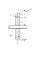
- FIG. 15 is a cross-sectional view showing a modification of the rotation transmission mechanism shown in FIG.
- the grooves 3Fb and the protrusions 4Ba of the rotation transmission mechanism 100 shown in FIG. 9 are formed at substantially the center in the thickness direction of the outer peripheral projection 3F.
- the outer projections 3F A groove 3Fb and a protrusion 4Ba are formed on one or the other side edge in the thickness direction.
- the groove 3Fb and the protrusion 4Ba are formed on one side edge (first side edge) in the thickness direction of the outer peripheral convex portion 3F, and the other two outer peripheral convex portions 3F in the thickness direction of the outer peripheral convex portion 3F. It is desirable to form the groove 3Fb and the protrusion 4Ba on the edge (second side edge located on the opposite side of the first side edge). As a result, the internal rotation member 130 can be incorporated into the external rotation member 140 in a state of being engaged with each other.
- a groove is formed in the outer peripheral convex portion 3F of the inner rotating member 130 (130 '), and a protrusion is formed in the annular portion 4B of the outer rotating member 140 (140').
- the present invention is not limited to such a structure, and a protrusion is formed on the outer peripheral convex portion 3F of the internal rotation member 130 (130 ′), and a groove is formed on the annular portion 4B of the external rotation member 140 (140 ′). Also good.
- the rotation transmission mechanism 100 according to the second embodiment described above is provided in a bicycle as in the first embodiment, for example.
- the outer peripheral convex portion 3F of the internal rotation member 130 (130 ') rotates with respect to the annular portion 4B of the external rotation member 140 (140').
- the outer peripheral convex portion 3F is guided by the groove 3Fb and the protrusion 4Ba, thereby causing blurring between the inner rotating member 130 (130 ′) and the outer rotating member 140 (140 ′) in the rotation axis direction.
- the internal rotation member 130 (130 ′) rotates.
- the groove 3Fb and the protrusion 4Ba are slidably moved along the rotation direction of the rotation transmission mechanism in the outer circumferential convex portion 3F and the annular portion 4B with respect to the annular portion 4B. It functions as the guide part 150 which guides in this way.
- the annular portion 4B is provided between the outer peripheral convex portion 3F of the inner rotating member 130 (130 ′) and the annular portion 4B of the outer rotating member 140 (140 ′).
- a guide portion 150 is provided to guide the outer peripheral convex portion 3F so as to move slidably along the rotation direction of the rotation transmission mechanism.
- the internal rotation member 130 (130 ′) is rotated in the same direction as the external rotation member 140 (140 ′) by another member (for example, the internal rotation member inside the annular portion of the external rotation member).
- a side plate portion or a cover portion for slidably holding can be omitted. For this reason, it is possible to reduce the number of parts, improve the work efficiency of assembly, and reduce the possibility of failure due to problems such as joining between parts constituting the rotation transmission mechanism. Therefore, it is possible to provide a rotation transmission mechanism capable of realizing a bicycle and the like that are more usable than conventional ones.
- the groove 3Fb is formed on one surface of the outer peripheral convex portion 3F and the annular portion 4B facing each other, and the other surface is inserted into the groove 3Fb.
- the protrusion 4Ba is provided.
- FIG. 16 is a plan view showing the back surface (BS) of the rotation transmission mechanism according to Embodiment 3 of the present invention.
- FIG. 17 is a cross-sectional view taken along line AA shown in FIG.
- FIG. 18 is a plan view showing a first external member constituting the rotation transmission mechanism.
- FIG. 19 is a plan view showing a second external member constituting the rotation transmission mechanism.
- FIG. 20 is a plan view showing an internal rotation member constituting the rotation transmission mechanism.
- the rotation transmission mechanism 200 includes, for example, an internal rotation member 230 through which a rotation shaft such as a crankshaft of a bicycle is inserted, and a rotation with respect to the internal rotation member 230
- An external rotating member 240 that is freely arranged and an elastic deformation portion 260 (elastic deformation body) are provided.
- the external rotation member 240 is disposed outside the first external member 240A, the second external member 240B fixed to the first external member 240A, and the first external member 240A.
- the first cover part 210 and the second cover part 220 disposed outside the second external member 240B are provided.
- the first cover part 210 is exposed to the surface side FS of the rotation transmission mechanism 200 and is fixed to the first external member 240A by screwing.
- the second cover portion 220 is exposed on the back surface side BS of the rotation transmission mechanism 200 and is fixed to the second external member 240B with screws.
- the first external member 240A protrudes toward the inside of the annular portion 241A, the five chain ring fixing portions 242 provided outside the annular portion 241A, and the annular portion 241A.
- the five inner peripheral convex portions 243A, the cover attaching concave portion 244, and the five step portions 245 provided in the annular portion 241A are provided.
- the chain ring fixing portion 242 and the inner peripheral convex portion 243A are integrally formed with the annular portion 241A.
- the illustration of the chain ring is omitted.
- the chain ring can be fixed to the chain ring fixing portion 242.
- the first cover portion 210 is fitted in the cover mounting recess 244.
- Each of the five inner peripheral convex portions 243A has a substantially triangular shape having a vertex 243AT disposed at a position close to the center of the external rotating member 240.
- the vertex 243AT is chamfered, and a curved surface is formed at the vertex 243AT.
- Each of the inner peripheral convex portions 243A has two sides (surfaces) extending from the vertex 243AT toward the annular portion 241A. That is, each of the inner peripheral convex portions 243A has a radiation extending surface 243AH (first surface) extending from the vertex 243AT along the radial direction from the center of the outer rotating member 240 toward the radially outer side and reaching the annular portion 241A, and the radiation. It has an inclined surface 243AK (second surface) that is inclined at an acute angle with respect to the extending surface 243AH and extends from the vertex 243AT to reach the annular portion 241A.
- a curved surface is formed at a portion where the radiation extending surface 243AH and the annular portion 241A are connected.
- One end of the stepped portion 245 is located at a portion where the inclined surface 243AK and the annular portion 241A are connected, that is, the inclined surface 243AK is continuous with the stepped portion 245.
- Each of the inner peripheral convex portions 243A is formed with a through hole and a screw hole, and the second outer member 240B, the first cover portion 210, and the second cover portion 220 can be fixed to the inner peripheral convex portion 243A.
- the stepped portion 245 is a portion formed by partially removing one surface of the annular portion 241A. The thickness of the stepped portion 245 in the crankshaft direction is equal to that of the annular portion 241A. Less than the thickness.
- the second outer member 240B includes an annular portion 241B and five inner peripheral convex portions 243B provided so as to protrude toward the inside of the annular portion 241B.
- the inner peripheral convex portion 243B is formed integrally with the annular portion 241B. Further, the step portion 245 is not formed in the second external member 240B.
- Each of the five inner peripheral convex portions 243B has a substantially triangular shape corresponding to the inner peripheral convex portion 243A. That is, the inner peripheral convex portion 243B includes a chamfered vertex 243BT, a radiation extending surface 243BH (first surface), and an inclined surface 243BK (second surface).
- the shapes of the radiation extending surface 243BH and the inclined surface 243BK constituting the inner circumferential convex portion 243B are the same as the shapes of the radiation extending surface 243AH and the inclined surface 243AK constituting the inner circumferential convex portion 243A, respectively.
- the inner diameter of the annular portion 241B is the same as the inner diameter of the annular portion 241A, as shown in FIG. 17, when the second outer member 240B is fixed so as to overlap the first outer member 240A, a flat surface In view, the annular portion 241A coincides with the annular portion 241B, and the inner circumferential convex portion 243A coincides with the inner circumferential convex portion 243B. Further, since the annular portion 241B overlaps the annular portion 241A so as to face the step portion 245 of the first external member 240A, the annular portion 241A and the annular portion 241B have a step portion 245 and a circular portion between them.
- a groove 250 (guide portion) constituted by the ring portion 241B is formed.
- the protrusion 232T of the outer peripheral convex portion 232 is inserted into the groove 250, and the protrusion 232T is slidable inside the groove 250.
- the internal rotation member 230 includes an internal rotation member main body 231 located at the center of the internal rotation member 230, five outer peripheral protrusions 232 formed integrally with the internal rotation member main body 231, and the internal rotation member.
- a crankshaft insertion hole 233 (rotation shaft insertion hole) penetrating through the center of the main body 231.
- the internal rotation member 230 is disposed between the first external member 240 ⁇ / b> A and the second external member 240 ⁇ / b> B, that is, located in the center of the external rotation member 240.
- a crankshaft is fixed to the crankshaft insertion hole 233, and the rotational force of the crankshaft is transmitted to the internal rotation member 230.
- the five outer peripheral convex portions 232 have an elongated shape extending from the center of the internal rotation member 230 toward the radially outer side.
- Each of the outer peripheral convex portions 232 includes an inclined surface 232K continuous to the adjacent outer peripheral convex portion, a curved surface 232C formed on the surface opposite to the inclined surface 232K, and a protrusion 232T positioned at the tip of the outer peripheral convex portion 232. (Guide part).
- the curved surface 232C has a shape corresponding to the outer shape of the elastic deformation portion 260.
- the protrusion 232T is inserted into the groove 250.
- the protrusion 232T can slidably move in a limited space such as the inside of the groove 250.
- the thickness of the protrusion 232T in the crankshaft direction and the length of the protrusion 232T in the radial direction are determined so that the protrusion 232T slides appropriately with respect to the groove 250. If the gap formed between the protrusion 232T and the groove 250 is too large, blurring is likely to occur between the internal rotation member 230 and the external rotation member 240, which is not preferable.
- the outer peripheral convex portion 232 and the inner peripheral convex portion 243A (243B) are alternately arranged so that the inner peripheral convex portion 243A (243B) of the external rotating member 240 is positioned next to the outer peripheral convex portion 232 of the internal rotating member 230.
- the outer peripheral convex portion 232 is disposed between the inner peripheral convex portions 243A (243B) adjacent to each other, and one inner convex portion 232 is disposed between the adjacent outer peripheral convex portions 232.
- a plurality of inner circumferential convex portions 243A (243B) and a plurality of outer circumferential convex portions 232 are arranged so that the circumferential convex portions 243A (243B) are arranged.
- the elastic deformation portion 260 is disposed between the radiation extending surface 243AH (243BH) of the inner peripheral convex portion 243A (243B) and the curved surface 232C of the outer peripheral convex portion 232.
- a hole is provided in the center of the elastic deformation portion 260.
- the internal rotation member 230 rotates relative to the external rotation member 240, and the radiation extending surface.
- a compressive force is applied to the elastic deformation portion 260 located between 243AH (243BH) and the curved surface 232C of the outer peripheral convex portion 232, and the elastic deformation portion 260 is elastically deformed.
- the protrusion 232T slides with respect to the groove 250, but the protrusion 232T does not come off from the groove 250.
- the groove 250 functions as a rail that prevents the internal rotation member 230 from coming off between the first external member 240A and the second external member 240B. For this reason, the internal rotation member 230 rotates without blurring between the internal rotation member 230 and the external rotation member 240. Therefore, the same effect as in the second embodiment described above can be obtained.
- the present invention is not limited to the configuration of the third embodiment.
- the protrusion 232 ⁇ / b> T is inserted into each of the five grooves 250, but the protrusion 232 ⁇ / b> T may be inserted into each of the three grooves of the five grooves 250.
- the protrusion 232 ⁇ / b> T since the total area of the sliding surfaces of the groove 250 and the protrusion 232T is reduced, the area in which the internal rotary member 230 and the external rotary member 240 are rubbed is reduced, and the rotational force of the internal rotary member 230 is reduced. Resistance can be reduced.
- the protrusion 232T is inserted into each of one or two of the five grooves 250 because blurring is likely to occur between the inner rotating member 230 and the outer rotating member 240. Therefore, it is preferable to employ a structure in which the protrusions 232T are inserted into the groove 250 at least at three or more locations.
- Embodiment 4 Next, the configuration of the rotation transmission mechanism according to the fourth embodiment of the present invention will be described with reference to FIGS.
- the same components as those in the first to third embodiments are denoted by the same reference numerals, and the description thereof is omitted.
- the external rotating member is composed of two members
- the internal rotating member is composed of two members.
- the fourth embodiment is different from the third embodiment.
- FIG. 21 is a plan view showing the back surface (BS) of the rotation transmission mechanism according to Embodiment 4 of the present invention.
- 22 is a cross-sectional view taken along line BB shown in FIG.
- FIG. 23 is a plan view showing an external rotation member constituting the rotation transmission mechanism.
- FIG. 24 is a plan view showing an internal rotation member constituting the rotation transmission mechanism.
- FIG. 25 is a cross-sectional view showing an internal rotation member constituting the rotation transmission mechanism.
- the rotation transmission mechanism 300 includes, for example, an internal rotation member 330 through which a rotation shaft such as a crankshaft of a bicycle is inserted, and rotation with respect to the internal rotation member 330.
- An external rotating member 340 that is freely arranged and an elastic deformation portion 360 (elastic deformation body) are provided.
- the external rotating member 340 has an annular part 341, five chain ring fixing parts 342 provided on the outer side of the annular part 341, and an inner side of the annular part 341.
- Five inner peripheral projections 343 provided so as to protrude, a cover attachment recess 344, five projections 345 (guide portions) provided on the annular portion 341, and an external rotation member on the back surface side BS of the rotation transmission mechanism 300 340 includes a first cover part 310 disposed on the outer side of 340 and a second cover part 320 fitted in the cover mounting recess 344.
- the chain ring fixing part 342 and the inner peripheral convex part 343 are formed integrally with the annular part 341.
- the chain ring can be fixed to the chain ring fixing portion 342.
- the first cover part 310 is exposed to the surface side FS of the rotation transmission mechanism 300 and is fixed to the annular part 341 with screws.
- the second cover portion 320 is exposed on the back surface side BS of the rotation transmission mechanism 300 and is fixed to the annular portion 341 with screws.
- Each of the five inner peripheral convex portions 343 has a substantially triangular shape having a vertex 343T arranged at a position close to the center of the external rotating member 340.
- the vertex 343T is chamfered, and a curved surface is formed at the vertex 343T.
- Each of the inner peripheral convex portions 343 has two sides (surfaces) extending from the vertex 343T toward the annular portion 341. That is, each of the inner circumferential convex portions 343 includes a radiation extending surface 343H (first surface) that extends from the vertex 343T along the radial direction from the center of the external rotating member 340 toward the radially outer side and reaches the annular portion 341, and the radiation. It has an inclined surface 343K (second surface) that is inclined at an acute angle with respect to the extending surface 343H and extends from the apex 343T to reach the annular portion 341.
- a curved surface is formed at a portion where the radiation extending surface 343H and the annular portion 341 are connected.
- One end of the protrusion 345 is located at a portion where the inclined surface 343K and the annular portion 341 are connected, that is, the inclined surface 343K is continuous with the protrusion 345.
- Each of the inner peripheral convex portions 343 is formed with a screw hole, and the first cover portion 310 and the second cover portion 320 can be fixed to the inner peripheral convex portion 343.
- the protrusion 345 is a part formed by partially removing both surfaces of the annular part 341, and the thickness of the protrusion 345 in the crankshaft direction is greater than the thickness of the annular part 341. Is also small.
- the protrusion 345 is inserted into the groove 350 (guide portion) of the internal rotation member 330, and the protrusion 345 is slidable inside the groove 350.
- the internal rotation member 330 includes an internal rotation member main body 331 located at the center of the internal rotation member 330, and five outer peripheral convex portions 332 (332A, 332B) integrally formed with the internal rotation member main body 331. And a crankshaft insertion hole 333 (rotation shaft insertion hole) penetrating through the center of the internal rotation member main body 331.
- the internal rotation member 330 includes a first internal member 330 ⁇ / b> A and a second internal member 330 ⁇ / b> B that are members separable from each other in a cross-sectional view.
- first internal member 330A and the second internal member 330B are fixed to each other, screwing and fixing are performed using screw holes and through holes provided in the tip region of the outer peripheral convex portion 332.
- the first internal member 330A has a first protrusion 330AT provided at the tip of the outer peripheral convex portion 332A.
- the second inner member 330B has a second protrusion 330BT provided at the tip of the outer peripheral protrusion 332B.
- the first inner member 330A and the second inner member 330B are overlapped so that the first protrusion 330AT and the second protrusion 330BT are separated from each other, and are fixed to the outer peripheral protrusion 332 by performing the above-described screw fastening.
- An internal rotation member 330 having a groove 350 (guide portion) is formed. That is, the groove 350 is formed between the first protrusion 330AT and the second protrusion 330BT.
- the five outer peripheral protrusions 332 have an elongated shape that extends radially outward from the center of the internal rotation member 330.
- Each of the outer peripheral convex portions 332 includes an inclined surface 332K continuous to the adjacent outer peripheral convex portion, a curved surface 332C formed on a surface opposite to the inclined surface 332K, and a first end positioned at the distal end of the outer peripheral convex portion 332.
- the curved surface 332C has a shape corresponding to the outer shape of the elastic deformation portion 360.
- the first internal member 330A and the second internal member 330B are separated from each other.
- the second internal member 330B is disposed in the external rotation member 340 so that the second protrusion 330BT faces the protrusion 345 of the external rotation member 340.
- the first internal member 330A is disposed in the external rotary member 340 so that the first protrusion 330AT faces the protrusion 345 of the external rotary member 340.
- the first internal member 330A and the second internal member 330B are fixed by screwing. As a result, the protrusion 345 is inserted into the groove 350.
- the protrusion 345 can move slidably in a limited space such as the inside of the groove 350.
- the thickness of the protrusion 345 in the crankshaft direction and the length of the protrusion 345 in the radial direction are determined so that the protrusion 345 appropriately slides with respect to the groove 350. If the gap generated between the protrusion 345 and the groove 350 is too large, blurring is likely to occur between the internal rotation member 330 and the external rotation member 340, which is not preferable.
- first internal member 330A and the second internal member 330B are arranged with respect to the external rotating member 340 is not limited to the order described above.
- the first internal member 330A may be disposed in the external rotating member 340 first, and then the second internal member 330B may be disposed in the external rotating member 340.
- the internal rotation member 330 is disposed inside the external rotation member 340, as shown in FIG. Located in the center.
- a crankshaft is fixed to the crankshaft insertion hole 333, and the rotational force of the crankshaft is transmitted to the internal rotation member 330.
- the outer peripheral convex portions 332 are alternately arranged with the inner peripheral convex portions 343 so that the inner peripheral convex portions 343 of the external rotating member 340 are positioned next to the outer peripheral convex portions 332 of the internal rotating member 330.
- one outer peripheral convex portion 332 is disposed between the inner peripheral convex portions 343 adjacent to each other, and one inner peripheral convex portion 343 is disposed between the outer peripheral convex portions 332 adjacent to each other.
- a plurality of inner peripheral convex portions 343 and a plurality of outer peripheral convex portions 332 are disposed so as to be disposed.
- an elastic deformation portion 360 is disposed between the radiation extending surface 343H of the inner peripheral convex portion 343 and the curved surface 332C of the outer peripheral convex portion 332.
- a hole is provided in the center of the elastic deformation portion 360.
- the internal rotation member 330 rotates relative to the external rotation member 340, and the radiation extending surface.
- a compression force is applied to the elastic deformation portion 360 positioned between 343H and the curved surface 332C of the outer peripheral convex portion 332, and the elastic deformation portion 360 is elastically deformed.
- the protrusion 345 slides with respect to the groove 350, but the protrusion 345 does not come off from the groove 350.
- the groove 350 functions as a rail that prevents the internal rotation member 330 from being detached from the external rotation member 340. For this reason, the internal rotation member 330 rotates without blurring between the internal rotation member 330 and the external rotation member 340. Therefore, the same effects as those of the second and third embodiments described above can be obtained.
- the present invention is not limited to the configuration of the fourth embodiment.
- the protrusion 345 is inserted into each of the five grooves 350, but the protrusion 345 may be inserted into each of the three grooves of the five grooves 350. In this case, the same effect as in the third embodiment described above can be obtained.
- the rotation transmission mechanisms 1 and 100 used in the bicycle have been described as examples.
- the rotation transmission mechanism according to the embodiment of the present invention is not necessarily limited to such applications.
- the rotation transmission mechanism according to the embodiment of the present invention can be used for a mechanism having wheels, for example, a normal bicycle, a power-assisted bicycle, a civil unicycle, a wheelchair, a rickshaw, a rear car, etc., and obtains the same effect. be able to.
- it can be used not only for moving means but also for general mechanisms involving rotation, for example, home appliances, rotating brushes, mowers, generators with rotating mechanisms such as wind power generation.
Landscapes
- Engineering & Computer Science (AREA)
- Mechanical Engineering (AREA)
- General Engineering & Computer Science (AREA)
- Chemical & Material Sciences (AREA)
- Combustion & Propulsion (AREA)
- Transportation (AREA)
- Physics & Mathematics (AREA)
- Acoustics & Sound (AREA)
- Aviation & Aerospace Engineering (AREA)
- Transmission Devices (AREA)
- Toys (AREA)
Abstract
本発明の回転伝達機構は、内部回転部材と、前記内部回転部材に対して回動自在に配設される外部回転部材とを備える。前記内部回転部材は、外周側に突出する外周凸部を備える。前記外部回転部材は、円環部及び内周凸部を備える。前記外周凸部は、前進によって回転伝達機構が回転する前進回転方向に沿って前記外周凸部の中心よりもずれた位置にある前進面を有する。前記前進面と前記内周凸部との間には、弾性変形部が配設されている。前記外周凸部及び前記円環部には、前記円環部に対して前記外周凸部を回転伝達機構の回転方向に沿って摺動可能に移動するようにガイドするガイド部が設けられている。
Description
本発明は、回転伝達機構に関し、特に、自転車のクランク軸等の回転軸に装着して使用される回転伝達機構に関する。
本願は、2017年3月8日に日本に出願された特願2017-044078号に基づき優先権を主張し、その内容をここに援用する。
本願は、2017年3月8日に日本に出願された特願2017-044078号に基づき優先権を主張し、その内容をここに援用する。
運転者が人力で車輪を回転させる自転車の場合、自転車が一旦走り出せば、小さな力で走行することができる。しかしながら、発進時、加速時、登坂等における自転車の漕ぎ始めのときでは、運転者は自転車から特に大きな反発力を受け、入力したエネルギーの一部が、衝撃として膝、足首、腰などに跳ね返り、人体に大きな負荷を発生させるだけでなく、入力エネルギーを効率的に利用できず、推進力の低下につながっていた。そして、自転車の急発進、急加速を行う場合、急な坂道を登る場合、自転車の運転者の体重や積み荷の重量が重い場合などには、特に人体への負荷(抗力)が大きくなり、その分、必要なエネルギーも増大していた。
自転車における力の伝達においては、足の上下運動をクランクによって回転運動に変換する。このため、特に上死点及び下死点においてスムーズに脚力を自転車に伝達することは困難であり、膝や足首への負担増加を招くと共に、トルクの途切れ、スピードの低下が発生する。さらに、低速で自転車を走行する場合には、自転車のふらつきが発生し易く、走行の安定性が低下するという問題点があった。
自転車における力の伝達においては、足の上下運動をクランクによって回転運動に変換する。このため、特に上死点及び下死点においてスムーズに脚力を自転車に伝達することは困難であり、膝や足首への負担増加を招くと共に、トルクの途切れ、スピードの低下が発生する。さらに、低速で自転車を走行する場合には、自転車のふらつきが発生し易く、走行の安定性が低下するという問題点があった。
そこで、本発明者は、上記問題点を解決すべく、「回転軸を有する内部回転部材と前記内部回転部材の前記回転軸に回動自在に配設される外部回転部材とを有する自転車用回転伝達機構と、前記自転車用回転伝達機構の前記内部回転部材の前記両端部に180度の位相差で配設される左右のクランクアームと、前記クランクアームの端部に回動自在に配設されるペダルと、を備えた自転車」を提案している(特許文献1参照)。特に、この自転車においては、前記内部回転部材が、前記回転軸と一体に形成され又は前記回転軸の外周に固設され前記回転軸の外周側に突出する1以上の外周凸部を有し、前記外部回転部材が、前記内部回転部材の前記外周凸部の側部位置で前記回転軸に回動自在に挿設される側板部と、前記内部回転部材の前記外周凸部の外側で前記回転軸と同心円状に前記側板部の外周に立設される外筒部と、前記外筒部の内周側に突出するように前記側板部及び/又は前記外筒部と一体に形成され或いは前記側板部及び/又は前記外筒部に固定され前記内部回転部材の前記外周凸部と交互に配置される1以上の内周凸部と、を有し、前記外部回転部材の前記側板部又は前記外筒部にチェーンリングが形設又は固設され、前記外周凸部と前進する際の前記外周凸部の回転方向側の前記内周凸部との間に弾性変形部が配設され、前記内部回転部材と前記外部回転部材が相対的に回転する際に、前記弾性変形部が、前記外周凸部と前記内周凸部の間に挟まれて弾性変形する。
特許文献1に開示された自転車によれば、以下の効果が得られる。
(1)人力によって車輪を回転させて走行する自転車の回転軸に自転車用回転伝達機構を配設することにより、自転車用回転伝達機構が、発進、加速、登坂等の初動時や走行中に外部から受ける大きな負荷などによって生じる衝撃エネルギーや過大な入力エネルギーを確実に吸収して蓄え、人体への負荷を大幅に低減できる。
(2)自転車用回転伝達機構は、蓄えたエネルギーを、入力エネルギーが減少した時或いは途切れた時に、回転軸の回転に無駄なく有効に利用することができ、回転伝達の確実性、効率性に優れ、部品点数の少ない簡素な構成で軽量化を図ることができる。
(3)自転車用回転伝達機構は、分解や組立が容易でメンテナンス性、生産性に優れ、既存の自転車に簡便に組込むことができ、量産性、組立作業性、省スペース性、汎用性に優れる。このような自転車用回転伝達機構を備えることにより、使用者の足腰などにかかる負荷を低減することができる。
(4)重い荷物を運搬する際や体重の重い人を自転車に乗せた際にも、自転車用回転伝達機構は、加速性、回転トルクの均一性、低速運転時の安定性に優れ、複雑な操作が不要で、運転者の膝や足首などにかかる負荷を低減することができる。
(5)女性や年配者が自転車に乗る場合、自転車に重い荷物や子供を乗せる際に主婦等が運転者である場合でも、自転車用回転伝達機構を備える自転車を手軽に運転することができる。また、坂道や抵抗の大きな道でも楽に走行することができる日用品として自転車を利用するだけでなく、加速性、回転トルクの均一性、低速運転時の安定性に優れ、リハビリ用や競技用としても使用することができ、動作の安定性、取り扱い性、汎用性に優れた自転車を提供できる。
(1)人力によって車輪を回転させて走行する自転車の回転軸に自転車用回転伝達機構を配設することにより、自転車用回転伝達機構が、発進、加速、登坂等の初動時や走行中に外部から受ける大きな負荷などによって生じる衝撃エネルギーや過大な入力エネルギーを確実に吸収して蓄え、人体への負荷を大幅に低減できる。
(2)自転車用回転伝達機構は、蓄えたエネルギーを、入力エネルギーが減少した時或いは途切れた時に、回転軸の回転に無駄なく有効に利用することができ、回転伝達の確実性、効率性に優れ、部品点数の少ない簡素な構成で軽量化を図ることができる。
(3)自転車用回転伝達機構は、分解や組立が容易でメンテナンス性、生産性に優れ、既存の自転車に簡便に組込むことができ、量産性、組立作業性、省スペース性、汎用性に優れる。このような自転車用回転伝達機構を備えることにより、使用者の足腰などにかかる負荷を低減することができる。
(4)重い荷物を運搬する際や体重の重い人を自転車に乗せた際にも、自転車用回転伝達機構は、加速性、回転トルクの均一性、低速運転時の安定性に優れ、複雑な操作が不要で、運転者の膝や足首などにかかる負荷を低減することができる。
(5)女性や年配者が自転車に乗る場合、自転車に重い荷物や子供を乗せる際に主婦等が運転者である場合でも、自転車用回転伝達機構を備える自転車を手軽に運転することができる。また、坂道や抵抗の大きな道でも楽に走行することができる日用品として自転車を利用するだけでなく、加速性、回転トルクの均一性、低速運転時の安定性に優れ、リハビリ用や競技用としても使用することができ、動作の安定性、取り扱い性、汎用性に優れた自転車を提供できる。
特許文献1の自転車は、上記の目的を達成するものであるが、本発明者は、特許文献1の自転車の使用性を更に向上すべく鋭意研究を重ね、本発明を完成させるに至った。
本発明は、従来よりも使用性に優れた自転車等を実現することが可能な回転伝達機構及びそれを備えた自転車を提供することを目的とする。
本発明者は、特許文献1に開示された自転車の使用性を更に向上すべく鋭意研究を重ね、本発明を完成させるに至った。
前記目的を達成するため、本発明の第1態様に係る回転伝達機構は、回転軸が挿通される内部回転部材と、前記内部回転部材に対して回動自在に配設される外部回転部材と、を備える。前記内部回転部材は、回転軸挿通孔を有する円盤状の内部回転部材本体と、前記内部回転部材本体に一体形成され又は前記内部回転部材本体に固設され前記内部回転部材本体の外周側に突出する1つ又は複数の外周凸部と、を備える。前記外部回転部材は、前記内部回転部材の前記外周凸部の外側で前記内部回転部材に対して回動自在に配設された円環部と、前記円環部の内周側に突出するように前記円環部に一体形成され又は前記円環部に固設され前記内部回転部材の前記外周凸部と交互に配置された1つ又は複数の内周凸部と、を備える。前記外周凸部は、前進によって回転伝達機構が回転する前進回転方向に沿って前記外周凸部の中心よりもずれた位置にある前進面を有する。前記前進面と、前記前進回転方向にて前記前進面と対向する前記内周凸部との間には、弾性変形部が配設されている。前記内部回転部材と前記外部回転部材が相対的に回転する際に、前記弾性変形部が、前記外周凸部と前記内周凸部の間に挟まれて弾性変形する。前記外周凸部及び前記円環部には、前記円環部に対して前記外周凸部を回転伝達機構の回転方向に沿って摺動可能に移動するようにガイドするガイド部が設けられている。
前記目的を達成するため、本発明の第1態様に係る回転伝達機構は、回転軸が挿通される内部回転部材と、前記内部回転部材に対して回動自在に配設される外部回転部材と、を備える。前記内部回転部材は、回転軸挿通孔を有する円盤状の内部回転部材本体と、前記内部回転部材本体に一体形成され又は前記内部回転部材本体に固設され前記内部回転部材本体の外周側に突出する1つ又は複数の外周凸部と、を備える。前記外部回転部材は、前記内部回転部材の前記外周凸部の外側で前記内部回転部材に対して回動自在に配設された円環部と、前記円環部の内周側に突出するように前記円環部に一体形成され又は前記円環部に固設され前記内部回転部材の前記外周凸部と交互に配置された1つ又は複数の内周凸部と、を備える。前記外周凸部は、前進によって回転伝達機構が回転する前進回転方向に沿って前記外周凸部の中心よりもずれた位置にある前進面を有する。前記前進面と、前記前進回転方向にて前記前進面と対向する前記内周凸部との間には、弾性変形部が配設されている。前記内部回転部材と前記外部回転部材が相対的に回転する際に、前記弾性変形部が、前記外周凸部と前記内周凸部の間に挟まれて弾性変形する。前記外周凸部及び前記円環部には、前記円環部に対して前記外周凸部を回転伝達機構の回転方向に沿って摺動可能に移動するようにガイドするガイド部が設けられている。
ここで、回転伝達機構においては、内部回転部材の外周凸部と、自転車が前進する際の外周凸部の回転方向側の外部回転部材の内周凸部との間に、即ち、外周凸部の前進面と、前記前進回転方向にて前記前進面と対向する前記内周凸部との間に、弾性変形部が配設されている。内部回転部材と外部回転部材とが相対的に回転する際に、弾性変形部が、外周凸部と前記内周凸部の間に挟まれて弾性変形する。このような構造を有する回転伝達機構を、例えば、自転車の回転軸に設けることで、発進、加速、登坂等の初動時や走行中に外部から受ける大きな負荷などによって生じる衝撃エネルギーや過大な入力エネルギーを確実に吸収して蓄え、人体への負荷を大幅に低減できる。蓄えたエネルギーを入力エネルギーが減少した時或いは途切れた時に回転軸の回転に無駄なく有効に利用することができる。
ところで、上記のような回転伝達機構であっても、内部回転部材に対して外部回転部材が回転した際に、回転方向に対する3次元的な直角方向(回転に対する慣性モーメントの方向の軸)において、この2つの回転部材(内部回転部材、外部回転部材)の間で微妙なずれを生じる場合がある。
本発明の第1態様に係る回転伝達機構の構成によれば、内部回転部材の外周凸部及び外部回転部材の円環部に、円環部に対して外周凸部が、回転方向に沿って摺動可能に移動するようにガイドするガイド部を設けた。
これにより、内部回転部材に対して外部回転部材が回転した際に、ガイド部により、内部回転部材の回転方向への移動がガイドされるので、回転軸方向における内部回転部材と外部回転部材との間にブレ(ずれ)が発生することを防止することができる。
よって、回転軸方向における上述したブレによる回転力のロスを低減できる。また、例えば、内部回転部材を、外部回転部材と同じ方向へ回転させるための他の部材(例えば、外部回転部材の円環部内側に、内部回転部材を摺動可能に保持するための側板部やカバー部)を省略することもできる。このため、部品点数を減らすことが可能となり、組み立ての作業効率が向上し、部品間の接合等の不具合に起因する故障の可能性を低減できる。
したがって、従来よりも使用性に優れた自転車等を実現することが可能な回転伝達機構を提供できる。
これにより、内部回転部材に対して外部回転部材が回転した際に、ガイド部により、内部回転部材の回転方向への移動がガイドされるので、回転軸方向における内部回転部材と外部回転部材との間にブレ(ずれ)が発生することを防止することができる。
よって、回転軸方向における上述したブレによる回転力のロスを低減できる。また、例えば、内部回転部材を、外部回転部材と同じ方向へ回転させるための他の部材(例えば、外部回転部材の円環部内側に、内部回転部材を摺動可能に保持するための側板部やカバー部)を省略することもできる。このため、部品点数を減らすことが可能となり、組み立ての作業効率が向上し、部品間の接合等の不具合に起因する故障の可能性を低減できる。
したがって、従来よりも使用性に優れた自転車等を実現することが可能な回転伝達機構を提供できる。
本発明の第1態様に係る回転伝達機構において、前記ガイド部は、前記外周凸部及び前記円環部の互いに対向する2つの面にそれぞれ形成されている。前記外周凸部及び前記円環部の前記2つの面のうち一方の面には溝が形成されてもよい。この場合、他方の面には前記溝に挿入される突起が形成されている。
この構成によれば、ガイド部において、外周凸部及び円環部の互いに対向する2つの面のうち一方の面に溝を形成し、他方の面にこの溝に挿入されている突起を設けた。
これにより、内部回転部材に外部回転部材を取り付ける際に、一方の面の溝に、他方の面の突起を挿入することで、外部回転部材を内部回転部材の適正な位置に組み付けることができるので、作業効率が向上する。
これにより、内部回転部材に外部回転部材を取り付ける際に、一方の面の溝に、他方の面の突起を挿入することで、外部回転部材を内部回転部材の適正な位置に組み付けることができるので、作業効率が向上する。
本発明の第1態様に係る回転伝達機構において、前記外部回転部材は、第1外部部材と、前記第1外部部材に重なるように固定された第2外部部材と、前記第1外部部材と前記第2外部部材との間に形成された前記ガイド部である溝とを備える。前記内部回転部材は、前記第1外部部材と前記第2外部部材との間に配置されており、かつ、前記外周凸部の先端に位置する前記ガイド部である突起を有する。前記溝の内部に、前記突起が挿入してもよい。
本発明の第1態様に係る回転伝達機構において、前記外部回転部材は、前記円環部に設けられた前記ガイド部である突起を備える。前記内部回転部材は、第1突出部を有する第1内部部材と、前記第1内部部材に重なるように固定されかつ第2突出部を有する第2内部部材と、前記第1突出部と前記第2突出部との間に形成された前記ガイド部である溝とを備える。前記溝の内部に、前記突起が挿入してもよい。
本発明の第2態様に係る自転車は、第1態様に係る回転伝達機構を備える。
この構成によれば、上記のような作用効果を奏する回転伝達機構を備えているので、従来よりも使用性に優れた自転車を提供することができる。
本発明によれば、従来よりも使用性に優れた自転車等を実現することが可能な回転伝達機構及び自転車を提供することができる。
以下、好適な実施の形態を用いて本発明をさらに具体的に説明する。但し、下記の実施の形態は本発明を具現化した例に過ぎず、本発明は、以下に述べる実施の形態に限定されない。
[実施の形態1]
(回転伝達機構の構成)
まず、本発明の実施の形態1における回転伝達機構の構成について、図1~図6Bを参照しながら説明する。
(回転伝達機構の構成)
まず、本発明の実施の形態1における回転伝達機構の構成について、図1~図6Bを参照しながら説明する。
図1は、本発明の実施の形態1における回転伝達機構の表面を示す平面図である。図2は、当該回転伝達機構の裏面を示す平面図である。図3は、図1に示すIII-III線に沿う断面図である。図4Aは、当該回転伝達機構を構成する外部回転部材の表面を示す平面図である。図4Bは、当該回転伝達機構を構成する内部回転部材の表面を示す平面図である。図4Cは、当該回転伝達機構を構成するカバー部の表面を示す平面図である。図5は、当該回転伝達機構を構成する内部回転部材の裏面を示す平面図である。図6Aは、当該回転伝達機構を示す図であって、カバー部を取り外した状態を示す平面図である。図6Bは、図6Aの符号Xが示す部分を拡大した拡大平面図である。
図3において、符号FSは、回転伝達機構の表面を示しており、符号BSは、回転伝達機構の裏面を示している。即ち、符号FSによって示された平面図は図1に対応しており、符号BSによって示された平面図は図2に対応している。
図3において、符号FSは、回転伝達機構の表面を示しており、符号BSは、回転伝達機構の裏面を示している。即ち、符号FSによって示された平面図は図1に対応しており、符号BSによって示された平面図は図2に対応している。
図1~図6Bに示すように、本実施の形態に係る回転伝達機構1は、例えば、自転車のクランク軸等の回転軸が挿通する内部回転部材3と、内部回転部材3に対して回動自在に配設される外部回転部材4と、弾性変形部6(弾性変形体)とを備えている。
(内部回転部材)
内部回転部材3は、円盤状の内部回転部材本体3aと、内部回転部材本体3aの表面に一体形成された円柱状の凸部3bと、内部回転部材本体3aの裏面に一体形成された円柱状の凸部3cと、凸部3bに形成された圧入用凹部3dと、凸部3cと内部回転部材本体3aを貫通して圧入用凹部3dに至る四角筒状のクランク軸挿通孔3e(回転軸挿通孔)と、を備えている。
図3に示すように、内部回転部材本体3aの表面から突出している凸部3bの高さ(クランク軸の方向における内部回転部材本体3aの表面から凸部3bの端面までの距離)は、後述するカバー部4cの厚さよりも大きい。
また、内部回転部材本体3aの裏面から突出している凸部3cの高さ(クランク軸の方向における内部回転部材本体3aの裏面から凸部3cの端面までの距離)は、後述する側板部4aの厚さよりも大きい。
圧入用凹部3dは、図4Bに示すように略長円状の形状を有し、図3に示すように、凸部3bの高さに略対応する深さを有する。
また、内部回転部材3は、内部回転部材本体3aに一体形成されて内部回転部材本体3aの外周部から外側に向けて突出する5つの外周凸部3fを備えている。当該外周凸部3fの表面と裏面にはそれぞれベアリング用ボール3g,3hが回転可能に保持されている。内部回転部材3の径方向(クランク軸を中心とする遠心方向)において、ボール3g,3hは、外周凸部3fの突出量(長さ)に対して45~65%、好ましくは58~62%の位置にある。換言すると、内部回転部材3の径方向において、内部回転部材本体3aの外周面から外周凸部3fの外端までの距離を100%とすると、内部回転部材本体3aの外周面から45~65%、好ましくは58~62%だけ離れた位置に、ボール3g,3hは設けられている。
図6Bに示すように、複数の外周凸部3fのそれぞれは、前進面3ffと、前進面3ffとは反対側に位置する反対面3fbとを有する。換言すると、内部回転部材3の径方向における外周凸部3fの中心線CLから回転方向RDa(前進回転方向、自転車が前進する場合の回転伝達機構1の回転方向)に沿ってずれた位置、即ち、図6Bにおける外周凸部3fの右側の位置に、前進面3ffは位置している。その一方、内部回転部材3の径方向における外周凸部3fの中心線CLから回転方向RDaとは反対方向に沿ってずれた位置、即ち、図6Bにおける外周凸部3fの左側の位置に、反対面3fbは位置している。
内部回転部材3は、円盤状の内部回転部材本体3aと、内部回転部材本体3aの表面に一体形成された円柱状の凸部3bと、内部回転部材本体3aの裏面に一体形成された円柱状の凸部3cと、凸部3bに形成された圧入用凹部3dと、凸部3cと内部回転部材本体3aを貫通して圧入用凹部3dに至る四角筒状のクランク軸挿通孔3e(回転軸挿通孔)と、を備えている。
図3に示すように、内部回転部材本体3aの表面から突出している凸部3bの高さ(クランク軸の方向における内部回転部材本体3aの表面から凸部3bの端面までの距離)は、後述するカバー部4cの厚さよりも大きい。
また、内部回転部材本体3aの裏面から突出している凸部3cの高さ(クランク軸の方向における内部回転部材本体3aの裏面から凸部3cの端面までの距離)は、後述する側板部4aの厚さよりも大きい。
圧入用凹部3dは、図4Bに示すように略長円状の形状を有し、図3に示すように、凸部3bの高さに略対応する深さを有する。
また、内部回転部材3は、内部回転部材本体3aに一体形成されて内部回転部材本体3aの外周部から外側に向けて突出する5つの外周凸部3fを備えている。当該外周凸部3fの表面と裏面にはそれぞれベアリング用ボール3g,3hが回転可能に保持されている。内部回転部材3の径方向(クランク軸を中心とする遠心方向)において、ボール3g,3hは、外周凸部3fの突出量(長さ)に対して45~65%、好ましくは58~62%の位置にある。換言すると、内部回転部材3の径方向において、内部回転部材本体3aの外周面から外周凸部3fの外端までの距離を100%とすると、内部回転部材本体3aの外周面から45~65%、好ましくは58~62%だけ離れた位置に、ボール3g,3hは設けられている。
図6Bに示すように、複数の外周凸部3fのそれぞれは、前進面3ffと、前進面3ffとは反対側に位置する反対面3fbとを有する。換言すると、内部回転部材3の径方向における外周凸部3fの中心線CLから回転方向RDa(前進回転方向、自転車が前進する場合の回転伝達機構1の回転方向)に沿ってずれた位置、即ち、図6Bにおける外周凸部3fの右側の位置に、前進面3ffは位置している。その一方、内部回転部材3の径方向における外周凸部3fの中心線CLから回転方向RDaとは反対方向に沿ってずれた位置、即ち、図6Bにおける外周凸部3fの左側の位置に、反対面3fbは位置している。
(外部回転部材)
外部回転部材4は、側板部4aと、円環部4bと、カバー部4cとを備えている。側板部4aは、内部回転部材3の外周凸部3fの隣りに位置しており、内部回転部材3の凸部3cに対して回動自在である。側板部4aには、挿通孔4eが形成されており、この挿通孔4eには凸部3cが挿設されている。円環部4bは、内部回転部材3の外周凸部3fの外側で側板部4aの外周にネジ留め固定されている。カバー部4cは、側板部4aに対向配置された状態で凸部3bに対して回動自在である。カバー部4cには、挿通孔4fが形成されており、この挿通孔4fには凸部3bが挿設されている。カバー部4cは、円環部4bにネジ留め固定されている。
尚、内部回転部材3は、外周凸部3fの表面と裏面に保持されたベアリング用ボール3g,3hがそれぞれカバー部4c、側板部4a上を転がりながら回転する。これにより、内部回転部材3を滑らかに回転させることができる。
また、外部回転部材4は、5つの内周凸部4dを備えている。内周凸部4dは、円環部4bの内周側に向けて突出するように円環部4bに一体形成され、内部回転部材3の外周凸部3fと交互に配置されている。具体的に、回転伝達機構1の回転方向において、互いに隣接する内周凸部4dの間に1つの外周凸部3fが配置され、かつ、互いに隣接する外周凸部3fの間に1つの内周凸部4dが配置されるように、複数の内周凸部4dと複数の外周凸部3fとが配置されている。
さらに、外部回転部材4の円環部4bの裏面側の外周部には、チェーンリング5が固設されている。
外部回転部材4は、側板部4aと、円環部4bと、カバー部4cとを備えている。側板部4aは、内部回転部材3の外周凸部3fの隣りに位置しており、内部回転部材3の凸部3cに対して回動自在である。側板部4aには、挿通孔4eが形成されており、この挿通孔4eには凸部3cが挿設されている。円環部4bは、内部回転部材3の外周凸部3fの外側で側板部4aの外周にネジ留め固定されている。カバー部4cは、側板部4aに対向配置された状態で凸部3bに対して回動自在である。カバー部4cには、挿通孔4fが形成されており、この挿通孔4fには凸部3bが挿設されている。カバー部4cは、円環部4bにネジ留め固定されている。
尚、内部回転部材3は、外周凸部3fの表面と裏面に保持されたベアリング用ボール3g,3hがそれぞれカバー部4c、側板部4a上を転がりながら回転する。これにより、内部回転部材3を滑らかに回転させることができる。
また、外部回転部材4は、5つの内周凸部4dを備えている。内周凸部4dは、円環部4bの内周側に向けて突出するように円環部4bに一体形成され、内部回転部材3の外周凸部3fと交互に配置されている。具体的に、回転伝達機構1の回転方向において、互いに隣接する内周凸部4dの間に1つの外周凸部3fが配置され、かつ、互いに隣接する外周凸部3fの間に1つの内周凸部4dが配置されるように、複数の内周凸部4dと複数の外周凸部3fとが配置されている。
さらに、外部回転部材4の円環部4bの裏面側の外周部には、チェーンリング5が固設されている。
(弾性変形部)
図3に示すように、弾性変形部6は、合成ゴム等の弾性部材により構成されており、弾性変形が可能である。弾性変形部6は、カバー部4cと側板部4aとによって挟持され、円環部4bとによって囲まれている。後述するように、弾性変形部6の各々は、外周凸部3fの前進面3ffと、回転方向RDaにて前進面3ffと対向する内周凸部4dとの間に挟まれる。なお、図6A及び図8に示す弾性変形部6の個数は、5つであるが、弾性変形部6の個数は限定されない。弾性変形部6は、弾性変形しながら外部回転部材4から内部回転部材3に回転力を伝達する。また、弾性変形部6は、弾性変形部6に蓄力されたエネルギーを回転力として内部回転部材3に伝達する。
図3に示すように、弾性変形部6は、合成ゴム等の弾性部材により構成されており、弾性変形が可能である。弾性変形部6は、カバー部4cと側板部4aとによって挟持され、円環部4bとによって囲まれている。後述するように、弾性変形部6の各々は、外周凸部3fの前進面3ffと、回転方向RDaにて前進面3ffと対向する内周凸部4dとの間に挟まれる。なお、図6A及び図8に示す弾性変形部6の個数は、5つであるが、弾性変形部6の個数は限定されない。弾性変形部6は、弾性変形しながら外部回転部材4から内部回転部材3に回転力を伝達する。また、弾性変形部6は、弾性変形部6に蓄力されたエネルギーを回転力として内部回転部材3に伝達する。
回転伝達機構1は、次のような手順で組み立てられる。すなわち、まず、図2,図3に示すように、円環部4bの裏面側から当該円環部4bに側板部4aをネジ留め固定する。次いで、図3,図4A~図4C,図6Aに示すように、内部回転部材3の裏面側に位置する凸部3cを側板部4aの表面側FSから裏面側BSに向けて当該側板部4aの挿通孔4eに挿通する。これにより、内部回転部材3を円環部4b内に配置する。次いで、図1,図3,図4A~図4Cに示すように、内部回転部材3の表面側に位置する凸部3bをカバー部4cの挿通孔4fに挿通し、当該カバー部4cを円環部4bの表面にネジ留め固定する。
(外周凸部及び内周凸部に対する弾性変形部の接触構造)
図6A及び図6Bに示すように、外周凸部3fの前進面3ffと、内周凸部4dとの間には、合成ゴム製の弾性変形部6が配設されている。換言すると、外周凸部3fと、自転車が前進する際(回転伝達機構1が回転方向RDaに沿って回転する際)の当該外周凸部3fから回転方向に沿った位置にある内周凸部4dとの間に、弾性変形部6が配設されている。内部回転部材3と外部回転部材4が相対的に回転する際に、弾性変形部6が、外周凸部3fと内周凸部4dとの間に挟まれて弾性変形(圧縮変形)するようにされている。ここで、弾性変形部6の側方への変形、即ち、図3における回転伝達機構1の軸方向における弾性変形部6の変形は、側板部4aとカバー部4cとにより阻止され、これにより、運転者がペダルを踏み込むことによって回転伝達機構1に入力されるエネルギーの一部を弾性変形部6に効率的に蓄力することが可能となる。
図6A及び図6Bに示すように、外周凸部3fの前進面3ffと、内周凸部4dとの間には、合成ゴム製の弾性変形部6が配設されている。換言すると、外周凸部3fと、自転車が前進する際(回転伝達機構1が回転方向RDaに沿って回転する際)の当該外周凸部3fから回転方向に沿った位置にある内周凸部4dとの間に、弾性変形部6が配設されている。内部回転部材3と外部回転部材4が相対的に回転する際に、弾性変形部6が、外周凸部3fと内周凸部4dとの間に挟まれて弾性変形(圧縮変形)するようにされている。ここで、弾性変形部6の側方への変形、即ち、図3における回転伝達機構1の軸方向における弾性変形部6の変形は、側板部4aとカバー部4cとにより阻止され、これにより、運転者がペダルを踏み込むことによって回転伝達機構1に入力されるエネルギーの一部を弾性変形部6に効率的に蓄力することが可能となる。
図6Bに示すように、本実施の形態に係る回転伝達機構1において、外周凸部3fの回転方向に向く面(前進面3ff)の面積が、回転方向とは反対方向に向く面(反対面3fb、中心線CLから回転方向RDaとは反対方向に沿ってずれた位置にある面)の面積よりも10~15%程度、好ましくは12~13%程度広くなっている。このため、外周凸部3fと、自転車が前進する際の当該外周凸部3fから回転方向に沿った位置にある内周凸部4dとの間(前進面3ffと内周凸部4dとの間)に配設された弾性変形部6を、従来よりも広い面積(範囲)で圧縮変形させて、圧縮(弾性)エネルギーを効率良く弾性変形部6に蓄えることができる。この圧縮(弾性)エネルギーは、回転エネルギーに変換されて、自転車等の推進力として利用される。
より具体的には、外周凸部3fは、前進面3ff(回転方向に向く面)が反対面3fb(回転方向とは反対方向に向く面)よりも緩やかな傾きをもって形成されている。さらに、前進面3ff(回転方向に向く面)と内部回転部材本体3aとの境界部分には、前進面3ffと内部回転部材本体3aの外周面とを連続的に接続する曲面が形成されている。このような形状を採用することによって外周凸部3fの前進面3ff(回転方向に向く面)の面積を広くしたことにより、外周凸部3fの高さ(内部回転部材本体3aの外周面から外周凸部3fの外端までの距離)を低くすることが可能となり、回転伝達機構1の小型化を図ることができる。また、内部回転部材本体3aの外周面から外周凸部3fの外端に向かうにつれて弾性変形部6を圧縮する外周凸部3f(前進面3ff)の長さ(距離)が大きくなるため、より多くの圧縮エネルギーを蓄えることができる。
また、円環部4bの厚みを調整することにより、回転伝達機構1の回転時における遠心力を調整することができるので、回転の慣性力を調整することができる。
より具体的には、外周凸部3fは、前進面3ff(回転方向に向く面)が反対面3fb(回転方向とは反対方向に向く面)よりも緩やかな傾きをもって形成されている。さらに、前進面3ff(回転方向に向く面)と内部回転部材本体3aとの境界部分には、前進面3ffと内部回転部材本体3aの外周面とを連続的に接続する曲面が形成されている。このような形状を採用することによって外周凸部3fの前進面3ff(回転方向に向く面)の面積を広くしたことにより、外周凸部3fの高さ(内部回転部材本体3aの外周面から外周凸部3fの外端までの距離)を低くすることが可能となり、回転伝達機構1の小型化を図ることができる。また、内部回転部材本体3aの外周面から外周凸部3fの外端に向かうにつれて弾性変形部6を圧縮する外周凸部3f(前進面3ff)の長さ(距離)が大きくなるため、より多くの圧縮エネルギーを蓄えることができる。
また、円環部4bの厚みを調整することにより、回転伝達機構1の回転時における遠心力を調整することができるので、回転の慣性力を調整することができる。
内周凸部4dのうち、外周凸部3fの前進面3ff(回転方向に向く面)と対向する面は、凹んだ状態に形成されている。このため、外周凸部3fと、自転車が前進する際の当該外周凸部3fから回転方向に沿った位置にある内周凸部4dとの間(前進面3ffと内周凸部4dとの間)に配設される弾性変形部6の量を増やすことができる。従って、推進力として利用するのに十分な量の圧縮(弾性)エネルギーを弾性変形部6に蓄えることができる。この凹みによって形成される凹みの内側空間の体積は、弾性変形部6の体積に対して2~5%であることが好ましい。この凹みが大きすぎると、弾性変形部6の圧縮が不十分となるからである。
(回転伝達機構の使用例)
次に、本実施の形態における回転伝達機構1の使用例について、図7,図8をも参照しながら説明する。
次に、本実施の形態における回転伝達機構1の使用例について、図7,図8をも参照しながら説明する。
図7は、本発明の実施の形態1における回転伝達機構を自転車に使用した例を示す図であって、回転伝達機構の要部を示す断面図である。図8は、当該回転伝達機構を示す図であって、カバー部4cを取り外した状態で、かつ、弾性変形部が弾性変形(圧縮変形)された状態を示す平面図である。
図7に示すように、回転軸としての自転車のクランク軸2は、自転車のフレームと一体のクランク軸保持部7に左右のボールベアリング8a,8bを介して回動自在に保持されている。クランク軸2の右側端部は、内部回転部材3のクランク軸挿通孔3e(図3参照)に挿通して固定され、これにより、回転伝達機構1がクランク軸2に装着されている。また、クランク軸2の左右両端には、クランクアーム9a,9bが互いに180度の位相差をもって固定されている。図7中、参照符号10は、クランク軸2にクランクアーム9a,9bを固定するためのクランクアーム固定部材である。クランク軸2は、内部回転部材3のクランク軸挿通孔3eの四角筒と嵌合しており、両者は一体的に回転する。
クランクアーム9a,9bの端部には、回動自在なペダル(図示せず)が配設されている。
クランクアーム9a,9bの端部には、回動自在なペダル(図示せず)が配設されている。
以上のようにして自転車のクランク軸2に装着された回転伝達機構1の動作について、図6A~図8を参照しながら説明する。
図7において、運転者がクランクアーム9a,9bの端部に配設されたペダル(図示せず)を踏むと、クランク軸2と共に内部回転部材本体3aの外周に突設された外周凸部3fが、図6A,図8に示された矢印RDaの方向に回転する。
そして、クランク軸2が回転して、外周凸部3fが内周凸部4dに近づくと、弾性変形部6が、外周凸部3f(前進面3ff)と内周凸部4dとの間に挟まれることによって圧縮され、入力エネルギーの一部が弾性変形部6に蓄えられる。
クランク軸2の回転の初期(図6A→図8)では弾性変形部6が弾性変形するが、弾性変形部6の変形後は、クランク軸2の回転力が外周凸部3fから内周凸部4dに伝達され、クランク軸2からチェーンリング5までが略一体となって回転する。チェーンリング5に張設されたチェーン(図示せず)を介して、回転力が自転車の後輪側に設けられたスプロケットへと確実に伝達される。
弾性変形(圧縮変形)された弾性変形部6は、ペダルから回転伝達機構1へのエネルギーの入力が途切れたり弱まったりした時に復元し、復元エネルギーとして内周凸部4dを押圧して、外部回転部材4及びチェーンリング5を進行方向に回転させる。すなわち、弾性変形部6の圧縮(弾性)エネルギーが、回転エネルギーに変換されて、自転車の推進力として利用される。
そして、クランク軸2が回転して、外周凸部3fが内周凸部4dに近づくと、弾性変形部6が、外周凸部3f(前進面3ff)と内周凸部4dとの間に挟まれることによって圧縮され、入力エネルギーの一部が弾性変形部6に蓄えられる。
クランク軸2の回転の初期(図6A→図8)では弾性変形部6が弾性変形するが、弾性変形部6の変形後は、クランク軸2の回転力が外周凸部3fから内周凸部4dに伝達され、クランク軸2からチェーンリング5までが略一体となって回転する。チェーンリング5に張設されたチェーン(図示せず)を介して、回転力が自転車の後輪側に設けられたスプロケットへと確実に伝達される。
弾性変形(圧縮変形)された弾性変形部6は、ペダルから回転伝達機構1へのエネルギーの入力が途切れたり弱まったりした時に復元し、復元エネルギーとして内周凸部4dを押圧して、外部回転部材4及びチェーンリング5を進行方向に回転させる。すなわち、弾性変形部6の圧縮(弾性)エネルギーが、回転エネルギーに変換されて、自転車の推進力として利用される。
尚、本実施の形態においては、外周凸部3fと内周凸部4dを5つずつ設けた場合を例に挙げて説明したが、本発明は必ずしもこのような構成に限定されない。外周凸部3fの数及び内周凸部4dの数は、それぞれ1つ又は複数であればよいが、弾性変形部6が蓄えた力を円周方向に伝えるためには、外周凸部3fの数及び内周凸部4dの数は、4つ以上であることが好ましい。また、弾性変形部6の体積を十分に確保するためには、外周凸部3fと内周凸部4dの数は、8つ以下であることが好ましい。
また、本実施の形態においては、外周凸部3fが内部回転部材本体3aに一体形成されている場合を例に挙げて説明したが、本発明は必ずしもこのような構成に限定されない。外周凸部は、内部回転部材本体に固設されていてもよい。
また、本実施の形態においては、内周凸部4dが円環部4bに一体形成されている場合を例に挙げて説明したが、本発明は必ずしもこのような構成に限定されない。内周凸部は、円環部に固設されていてもよい。
また、本実施の形態においては、内周凸部4dが円環部4bに一体形成されている場合を例に挙げて説明したが、本発明は必ずしもこのような構成に限定されない。内周凸部は、円環部に固設されていてもよい。
また、本実施の形態においては、弾性変形部6が合成ゴム製である場合を例に挙げて説明したが、本発明は必ずしもこのような構成に限定されない。
弾性変形部は、内部回転部材3と外部回転部材4が相対的に回転する際に弾性変形(圧縮変形)し、変形後は内部回転部材3と外部回転部材4の間で回転を伝達できればよく、弾性変形部の形状、大きさ、変形量、弾性率などは、使用者の好みに応じて、適宜、選択することができる。弾性変形部としては、合成ゴムの他に、例えば、外周凸部3fと内周凸部4dとの間に封入される気体などを用いることもできる。
弾性変形部は、内部回転部材3と外部回転部材4が相対的に回転する際に弾性変形(圧縮変形)し、変形後は内部回転部材3と外部回転部材4の間で回転を伝達できればよく、弾性変形部の形状、大きさ、変形量、弾性率などは、使用者の好みに応じて、適宜、選択することができる。弾性変形部としては、合成ゴムの他に、例えば、外周凸部3fと内周凸部4dとの間に封入される気体などを用いることもできる。
[実施の形態2]
次に、本発明の実施の形態2における回転伝達機構の構成について、図9~図12を参照しながら説明する。なお、以下の説明において、実施の形態1と同様の構成には、同一の符号を付し、その説明を省略する。
図9は、本発明の実施の形態2における回転伝達機構の表面を示す平面図である。図10は、図9に示すIV-IV線に沿う断面図である。図11は、当該回転伝達機構を構成する内部回転部材の表面を示す平面図である。図12は、当該回転伝達機構を構成する外部回転部材の表面を示す平面図である。
次に、本発明の実施の形態2における回転伝達機構の構成について、図9~図12を参照しながら説明する。なお、以下の説明において、実施の形態1と同様の構成には、同一の符号を付し、その説明を省略する。
図9は、本発明の実施の形態2における回転伝達機構の表面を示す平面図である。図10は、図9に示すIV-IV線に沿う断面図である。図11は、当該回転伝達機構を構成する内部回転部材の表面を示す平面図である。図12は、当該回転伝達機構を構成する外部回転部材の表面を示す平面図である。
実施の形態2に係る回転伝達機構100は、カバー部等を設けることなく、内部回転部材130と外部回転部材140とが、ガイド部150により、係合している点において、実施の形態1と異なる。
実施の形態2に係る回転伝達機構100は、例えば、自転車のクランク軸等の回転軸が挿通する内部回転部材130と、内部回転部材130に対して回動自在に配設される外部回転部材140と、弾性変形部6と、を備えている。
(内部回転部材)
図11に示すように、内部回転部材130は、円盤状の内部回転部材本体3aと、内部回転部材本体3aを貫通する略四角筒状のクランク軸挿通孔3eと、内部回転部材本体3aに一体形成され内部回転部材本体3aの外周部から外側に向けて突出する4つの外周凸部3Fを備えている。
図11に示すように、内部回転部材130は、円盤状の内部回転部材本体3aと、内部回転部材本体3aを貫通する略四角筒状のクランク軸挿通孔3eと、内部回転部材本体3aに一体形成され内部回転部材本体3aの外周部から外側に向けて突出する4つの外周凸部3Fを備えている。
外周凸部3Fは、内部回転部材本体3aから離れるほど幅が広がる略扇形形状に形成されている。図9に示すように、外周凸部3Fは、後述する外部回転部材140の内周凸部4dの外部側弾性変形部当接面4daと対面する内部側弾性変形部当接面3Faを有する。
内部側弾性変形部当接面3Faには、弾性変形部6が取り付けられる。図11に示す例では、内部側弾性変形部当接面3Faは、内部回転部材本体3aの中心から放射方向に直線形状に延びている。本実施の形態は、このような構造に限られず、弾性変形部6の一部を保持する湾曲部が内部側弾性変形部当接面3Faに設けてもよい。また、内部側弾性変形部当接面3Faには、弾性変形部6を保持する保持部を形成してもよい。
また、外周凸部3Fは、外部回転部材140(図9、図12参照)の内周側の端面4tに面する端面3t(外周凸部3Fの外縁を形成する端面3t)を有する。端面3tには、外周凸部3Fの厚み方向(図10における左右方向)の略中央において、内部回転部材本体3a方向に彫り込まれた溝3Fbが形成されている。溝3Fbは、外部回転部材140(図9参照)の内周に沿った円弧形状に形成されている。
(内部回転部材の変形例)
図13A及び図13Bは、図11に示す内部回転部材の変形例の構成を説明する図である。図13Aは、内部回転部材の表面を示す平面図である。図13Bは、図13Aに示すV-V線に沿う断面図である。
本変形例において内部回転部材130’は、内部側弾性変形部当接面3Faに切り欠きが形成された外周凸部3Fを有する。即ち、内部回転部材130’の表面から見て(平面視において)半円形状に形成された欠き込み部3Fcが内部側弾性変形部当接面3Faに形成されている。本変形例において、弾性変形部6は、内部回転部材130’の表面から見て(平面視において)円形状に形成された円柱形状に形成されている。弾性変形部6の一部は、欠き込み部3Fcに挿入され、弾性変形部6の他部は、内部側弾性変形部当接面3Faから突出する。このように、欠き込み部3Fcを設けて、弾性変形部6の一部を欠き込み部3Fcの一部を挿入することで、例えば、回転伝達機構100の使用により、弾性変形部6が回転伝達機構100から外れてしまうのを防止することができる。
図13A及び図13Bは、図11に示す内部回転部材の変形例の構成を説明する図である。図13Aは、内部回転部材の表面を示す平面図である。図13Bは、図13Aに示すV-V線に沿う断面図である。
本変形例において内部回転部材130’は、内部側弾性変形部当接面3Faに切り欠きが形成された外周凸部3Fを有する。即ち、内部回転部材130’の表面から見て(平面視において)半円形状に形成された欠き込み部3Fcが内部側弾性変形部当接面3Faに形成されている。本変形例において、弾性変形部6は、内部回転部材130’の表面から見て(平面視において)円形状に形成された円柱形状に形成されている。弾性変形部6の一部は、欠き込み部3Fcに挿入され、弾性変形部6の他部は、内部側弾性変形部当接面3Faから突出する。このように、欠き込み部3Fcを設けて、弾性変形部6の一部を欠き込み部3Fcの一部を挿入することで、例えば、回転伝達機構100の使用により、弾性変形部6が回転伝達機構100から外れてしまうのを防止することができる。
(外部回転部材)
図12に示すように、外部回転部材140は、円環部4Bと、4つの内周凸部4dと、を備える。円環部4Bは、内部回転部材130の外周凸部3F(図9参照)の外側で内部回転部材130に対して回動自在に配設されている。4つの内周凸部4dの各々は、円環部4Bの内周部から内側に向けて突出するように設けられている。4つの内周凸部4dは、円環部4Bに一体形成されてもよいし、又は、円環部4Bに固設されてもよい。4つの内周凸部4dは、内部回転部材130を構成する4つの外周凸部3Fと交互に配置されている。具体的に、回転伝達機構100の回転方向において、互いに隣接する内周凸部4dの間に1つの外周凸部3Fが配置され、かつ、互いに隣接する外周凸部3Fの間に1つの内周凸部4dが配置されるように、4つの内周凸部4dと4つの外周凸部3Fとが配置されている。
図12に示すように、外部回転部材140は、円環部4Bと、4つの内周凸部4dと、を備える。円環部4Bは、内部回転部材130の外周凸部3F(図9参照)の外側で内部回転部材130に対して回動自在に配設されている。4つの内周凸部4dの各々は、円環部4Bの内周部から内側に向けて突出するように設けられている。4つの内周凸部4dは、円環部4Bに一体形成されてもよいし、又は、円環部4Bに固設されてもよい。4つの内周凸部4dは、内部回転部材130を構成する4つの外周凸部3Fと交互に配置されている。具体的に、回転伝達機構100の回転方向において、互いに隣接する内周凸部4dの間に1つの外周凸部3Fが配置され、かつ、互いに隣接する外周凸部3Fの間に1つの内周凸部4dが配置されるように、4つの内周凸部4dと4つの外周凸部3Fとが配置されている。
円環部4Bは、円環形状に形成され、円環部4Bの外周部(端面4tとは反対側)には、チェーンリング5が固設されている。
また、円環部4Bには、突起4Baが形成されている。突起4Baは、外部回転部材140の内周側の端面4tから、内側(内部回転部材130)に向けて突出し、外周凸部3Fの溝3Fb(図11参照)に、摺動可能に挿入される突起4Baは、円環部4Bの内周に沿った円弧形状に形成されている。
また、円環部4Bには、突起4Baが形成されている。突起4Baは、外部回転部材140の内周側の端面4tから、内側(内部回転部材130)に向けて突出し、外周凸部3Fの溝3Fb(図11参照)に、摺動可能に挿入される突起4Baは、円環部4Bの内周に沿った円弧形状に形成されている。
また、突起4Baの円環部4Bの円周に沿った長さLは、圧縮されていない状態の弾性変形部6の円環部4Bの円周に沿った長さよりも短くすることが望ましい。これにより、回転伝達機構100の以下の手順で組み立てることができる。まず、弾性変形部6が取り付けられていない内部回転部材130を、外部回転部材140の突起4Baが形成されていない部分に、外周凸部3Fを挿入するように配置する。この状態で、内部回転部材130を回転させ、溝3Fbに突起4Baを挿入する。その後、弾性変形部6が外部側弾性変形部当接面4daと内部側弾性変形部当接面3Faとの間に配置するように、弾性変形部6を回転伝達機構100に取り付けることで、回転伝達機構100が組み上がる。また、突起4Baの円環部4Bの円周に沿った長さLは、最大限圧縮された状態の弾性変形部6の円環部4Bの円周に沿った長さよりも長いことが望ましい。これにより、回転伝達機構100の使用時に、弾性変形部6が最大限圧縮されたときに、外部回転部材140から内部回転部材130が外れてしまうのを防止することができる。
なお、溝3Fbと突起4Baとの互いに摺接する面には、互いに接触した場合の摩擦を低減する部材(潤滑材粉体の被膜、ベアリング等)を配置するのが望ましい。
(外部回転部材の変形例)
図14は、図11に示す外部回転部材の変形例を示す平面図である。
図12に示す突起4Baは円弧形状に形成されているが、本変形例における外部回転部材140’においては、突起4Ba’が棒形状に形成されている。このように、外部回転部材140’が内部回転部材130に取り付けられた状態において、外部回転部材140’の突起が外周凸部3Fの溝3Fbに摺動可能に挿入できれば、外部回転部材140’の突起は、任意の形状で形成することができる。
図14は、図11に示す外部回転部材の変形例を示す平面図である。
図12に示す突起4Baは円弧形状に形成されているが、本変形例における外部回転部材140’においては、突起4Ba’が棒形状に形成されている。このように、外部回転部材140’が内部回転部材130に取り付けられた状態において、外部回転部材140’の突起が外周凸部3Fの溝3Fbに摺動可能に挿入できれば、外部回転部材140’の突起は、任意の形状で形成することができる。
図15は、図9に示す回転伝達機構の変形例を示す断面図である。
図9に示す回転伝達機構100の溝3Fb及び突起4Baが、外周凸部3Fの厚み方向の略中央に形成されているが、本変形例における回転伝達機構100’においては、外周凸部3Fの厚み方向における一方又は他方の側縁に、溝3Fb及び突起4Baが形成されている。これにより、内部回転部材130を、例えば、金型を用いて形成する場合に、穴を形成するためのスライド金型を用いることなく、通常の金型を用いて形成できる。このため、生産コストを抑えることが可能となる。なお、この場合、4つの外周凸部3Fのうち、一部(例えば、外周凸部3Fの総数の半分、即ち、本実施の形態の例では2つの外周凸部3F)の外周凸部3Fにおいて、外周凸部3Fの厚み方向における一方の側縁(第1側縁)に溝3Fb及び突起4Baを形成し、残りの2つの外周凸部3Fにおいて、外周凸部3Fの厚み方向における他方の側縁(第1側縁とは反対側に位置する第2側縁)に溝3Fb及び突起4Baを形成するのが望ましい。これにより、外部回転部材140に内部回転部材130を互いに係合した状態に組み込むことが可能となる。
図9に示す回転伝達機構100の溝3Fb及び突起4Baが、外周凸部3Fの厚み方向の略中央に形成されているが、本変形例における回転伝達機構100’においては、外周凸部3Fの厚み方向における一方又は他方の側縁に、溝3Fb及び突起4Baが形成されている。これにより、内部回転部材130を、例えば、金型を用いて形成する場合に、穴を形成するためのスライド金型を用いることなく、通常の金型を用いて形成できる。このため、生産コストを抑えることが可能となる。なお、この場合、4つの外周凸部3Fのうち、一部(例えば、外周凸部3Fの総数の半分、即ち、本実施の形態の例では2つの外周凸部3F)の外周凸部3Fにおいて、外周凸部3Fの厚み方向における一方の側縁(第1側縁)に溝3Fb及び突起4Baを形成し、残りの2つの外周凸部3Fにおいて、外周凸部3Fの厚み方向における他方の側縁(第1側縁とは反対側に位置する第2側縁)に溝3Fb及び突起4Baを形成するのが望ましい。これにより、外部回転部材140に内部回転部材130を互いに係合した状態に組み込むことが可能となる。
なお、以上説明した例では、内部回転部材130(130’)における外周凸部3Fに溝を形成し、外部回転部材140(140’)における円環部4Bに突起を形成している。本発明は、このような構造に限らず、内部回転部材130(130’)における外周凸部3Fに突起を形成し、外部回転部材140(140’)における円環部4Bに溝を形成してもよい。
以上説明した実施の形態2に係る回転伝達機構100は、例えば、実施の形態1のように自転車に設けられている。この場合、運転者が自転車のペダルを踏むと、外部回転部材140(140’)の円環部4Bに対して、内部回転部材130(130’)の外周凸部3Fが回転する。このとき、外周凸部3Fは、溝3Fb及び突起4Baにガイドされることで、回転軸方向における内部回転部材130(130’)と外部回転部材140(140’)との間にブレが生じることなく、内部回転部材130(130’)は回転する。
このように溝3Fb及び突起4Baは、外周凸部3F及び円環部4Bには、円環部4Bに対して外周凸部3Fが、回転伝達機構の回転方向に沿って摺動可能に移動するようにガイドするガイド部150として機能する。
このような実施の形態2に係る回転伝達機構100によれば、内部回転部材130(130’)の外周凸部3F及び外部回転部材140(140’)の円環部4Bに、円環部4Bに対して外周凸部3Fが、回転伝達機構の回転方向に沿って摺動可能に移動するようにガイドするガイド部150を設けた。
これにより、内部回転部材130(130’)に対して外部回転部材140(140’)が回転した際に、ガイド部150により、内部回転部材130(130’)の回転方向への移動がガイドされる。このため、回転軸方向における内部回転部材130(130’)と外部回転部材140(140’)との間にブレが生じることを防止することができる。
よって、回転軸方向における上述したブレによる回転力のロスを低減できる。また、例えば、内部回転部材130(130’)を、外部回転部材140(140’)と同じ方向へ回転させるための他の部材(例えば、外部回転部材の円環部内側に、内部回転部材を摺動可能に保持するための側板部やカバー部)を省略することもできる。このため、部品点数を減らすことが可能となり、組み立ての作業効率が向上し、回転伝達機構を構成する部品間の接合等の不具合に起因する故障の可能性を低減できる。
したがって、従来よりも使用性に優れた自転車等を実現することが可能な回転伝達機構を提供できる。
これにより、内部回転部材130(130’)に対して外部回転部材140(140’)が回転した際に、ガイド部150により、内部回転部材130(130’)の回転方向への移動がガイドされる。このため、回転軸方向における内部回転部材130(130’)と外部回転部材140(140’)との間にブレが生じることを防止することができる。
よって、回転軸方向における上述したブレによる回転力のロスを低減できる。また、例えば、内部回転部材130(130’)を、外部回転部材140(140’)と同じ方向へ回転させるための他の部材(例えば、外部回転部材の円環部内側に、内部回転部材を摺動可能に保持するための側板部やカバー部)を省略することもできる。このため、部品点数を減らすことが可能となり、組み立ての作業効率が向上し、回転伝達機構を構成する部品間の接合等の不具合に起因する故障の可能性を低減できる。
したがって、従来よりも使用性に優れた自転車等を実現することが可能な回転伝達機構を提供できる。
また、回転伝達機構100によれば、ガイド部150において、外周凸部3F及び円環部4Bの互いに対向する面の一方の面に溝3Fbを形成し、他方の面にこの溝3Fbに挿入されている突起4Baを設けた。
これにより、内部回転部材130(130’)に外部回転部材140(140’)を取り付ける際に、一方の面に設けられた溝3Fbに、他方の面に設けられた突起4Baを挿入することで、外部回転部材140(140’)を内部回転部材130(130’)の適正な位置に組み付けることができるので、作業効率が向上する。
これにより、内部回転部材130(130’)に外部回転部材140(140’)を取り付ける際に、一方の面に設けられた溝3Fbに、他方の面に設けられた突起4Baを挿入することで、外部回転部材140(140’)を内部回転部材130(130’)の適正な位置に組み付けることができるので、作業効率が向上する。
[実施の形態3]
次に、本発明の実施の形態3における回転伝達機構の構成について、図16~図20を参照しながら説明する。なお、以下の説明において、実施の形態1、2と同様の構成には、同一の符号を付し、その説明を省略する。
次に、本発明の実施の形態3における回転伝達機構の構成について、図16~図20を参照しながら説明する。なお、以下の説明において、実施の形態1、2と同様の構成には、同一の符号を付し、その説明を省略する。
図16は、本発明の実施の形態3における回転伝達機構の裏面(BS)を示す平面図である。図17は、図16に示すA-A線に沿う断面図である。図18は、当該回転伝達機構を構成する第1外部部材を示す平面図である。図19は、当該回転伝達機構を構成する第2外部部材を示す平面図である。図20は、当該回転伝達機構を構成する内部回転部材を示す平面図である。
図16~図20に示すように、本実施の形態に係る回転伝達機構200は、例えば、自転車のクランク軸等の回転軸が挿通する内部回転部材230と、内部回転部材230に対して回動自在に配設される外部回転部材240と、弾性変形部260(弾性変形体)とを備えている。
(外部回転部材)
図17及び図18に示すように、外部回転部材240は、第1外部部材240Aと、第1外部部材240Aに固定された第2外部部材240Bと、第1外部部材240Aの外側に配置された第1カバー部210と、第2外部部材240Bの外側に配置された第2カバー部220とを備えている。
第1カバー部210は、回転伝達機構200の表面側FSに露出し、第1外部部材240Aにネジ留め固定されている。第2カバー部220は、回転伝達機構200の裏面側BSに露出し、第2外部部材240Bにネジ留め固定されている。
図17及び図18に示すように、外部回転部材240は、第1外部部材240Aと、第1外部部材240Aに固定された第2外部部材240Bと、第1外部部材240Aの外側に配置された第1カバー部210と、第2外部部材240Bの外側に配置された第2カバー部220とを備えている。
第1カバー部210は、回転伝達機構200の表面側FSに露出し、第1外部部材240Aにネジ留め固定されている。第2カバー部220は、回転伝達機構200の裏面側BSに露出し、第2外部部材240Bにネジ留め固定されている。
(第1外部部材)
図18に示すように、第1外部部材240Aは、円環部241Aと、円環部241Aの外側に設けられた5つのチェーンリング固定部242と、円環部241Aの内側に向けて突出するように設けられた5つの内周凸部243Aと、カバー取付け凹部244と、円環部241Aに設けられた5つの段差部245とを備える。チェーンリング固定部242及び内周凸部243Aは、円環部241Aに一体的に形成されている。
図16~図20においては、チェーンリングの図示が省略されている。チェーンリングは、チェーンリング固定部242に固設することが可能である。
図17に示すように、カバー取付け凹部244には、第1カバー部210が嵌合されている。
図18に示すように、第1外部部材240Aは、円環部241Aと、円環部241Aの外側に設けられた5つのチェーンリング固定部242と、円環部241Aの内側に向けて突出するように設けられた5つの内周凸部243Aと、カバー取付け凹部244と、円環部241Aに設けられた5つの段差部245とを備える。チェーンリング固定部242及び内周凸部243Aは、円環部241Aに一体的に形成されている。
図16~図20においては、チェーンリングの図示が省略されている。チェーンリングは、チェーンリング固定部242に固設することが可能である。
図17に示すように、カバー取付け凹部244には、第1カバー部210が嵌合されている。
5つの内周凸部243Aの各々は、外部回転部材240の中心に近い位置に配置される頂点243ATを有する略三角形の形状を有する。頂点243ATは面取りされており、頂点243ATに曲面が形成されている。内周凸部243Aの各々は、頂点243ATから円環部241Aに向けて延びる2つの辺(面)を有する。即ち、内周凸部243Aの各々は、外部回転部材240の中心から径方向外側に向かう放射方向に沿って頂点243ATから延びて円環部241Aに達する放射延在面243AH(第1面)と、放射延在面243AHに対して鋭角に傾斜して頂点243ATから延びて円環部241Aに達する傾斜面243AK(第2面)とを有する。
放射延在面243AHと円環部241Aとが繋がる部分には、曲面が形成されている。傾斜面243AKと円環部241Aとが繋がる部分には、段差部245の一端が位置しており、即ち、傾斜面243AKは段差部245と連続している。
内周凸部243Aの各々には、貫通孔及びネジ穴が形成されており、第2外部部材240B、第1カバー部210、及び第2カバー部220を内周凸部243Aに固定することが可能である。
図17に示すように、段差部245は、円環部241Aの片面を部分的に除去することにより形成された部位であり、クランク軸方向における段差部245の厚さは、円環部241Aの厚さよりも小さい。
内周凸部243Aの各々には、貫通孔及びネジ穴が形成されており、第2外部部材240B、第1カバー部210、及び第2カバー部220を内周凸部243Aに固定することが可能である。
図17に示すように、段差部245は、円環部241Aの片面を部分的に除去することにより形成された部位であり、クランク軸方向における段差部245の厚さは、円環部241Aの厚さよりも小さい。
(第2外部部材)
図19に示すように、第2外部部材240Bは、円環部241Bと、円環部241Bの内側に向けて突出するように設けられた5つの内周凸部243Bとを備える。内周凸部243Bは、円環部241Bに一体的に形成されている。また、第2外部部材240Bには、段差部245が形成されていない。
図19に示すように、第2外部部材240Bは、円環部241Bと、円環部241Bの内側に向けて突出するように設けられた5つの内周凸部243Bとを備える。内周凸部243Bは、円環部241Bに一体的に形成されている。また、第2外部部材240Bには、段差部245が形成されていない。
5つの内周凸部243Bの各々は、内周凸部243Aに対応する略三角形の形状を有する。即ち、内周凸部243Bは、面取された頂点243BTと、放射延在面243BH(第1面)と、傾斜面243BK(第2面)とを有する。換言すると、内周凸部243Bを構成する放射延在面243BH及び傾斜面243BKの形状は、各々、内周凸部243Aを構成する放射延在面243AH及び傾斜面243AKの形状と同じである。
また、円環部241Bの内径は、円環部241Aの内径と同じであるため、図17に示すように、第1外部部材240Aに第2外部部材240Bが重なるように固定されると、平面視において、円環部241Aは円環部241Bに一致し、内周凸部243Aは内周凸部243Bに一致する。また、円環部241Bは、第1外部部材240Aの段差部245に対向するように円環部241Aに重なるため、円環部241Aと円環部241Bとの間には、段差部245及び円環部241Bで構成される溝250(ガイド部)が形成される。後述するように、溝250には、外周凸部232の突起232Tが挿入され、溝250の内部において突起232Tは摺動可能である。
(内部回転部材)
図20に示すように、内部回転部材230は、内部回転部材230の中央に位置する内部回転部材本体231と、内部回転部材本体231に一体形成された5つの外周凸部232と、内部回転部材本体231の中央を貫通するクランク軸挿通孔233(回転軸挿通孔)と、を備えている。図17に示すように、内部回転部材230は、第1外部部材240Aと第2外部部材240Bとの間に配置され、即ち、外部回転部材240の中央に位置する。また、クランク軸挿通孔233にはクランク軸が固定されており、クランク軸の回転力は内部回転部材230に伝達される。
図20に示すように、内部回転部材230は、内部回転部材230の中央に位置する内部回転部材本体231と、内部回転部材本体231に一体形成された5つの外周凸部232と、内部回転部材本体231の中央を貫通するクランク軸挿通孔233(回転軸挿通孔)と、を備えている。図17に示すように、内部回転部材230は、第1外部部材240Aと第2外部部材240Bとの間に配置され、即ち、外部回転部材240の中央に位置する。また、クランク軸挿通孔233にはクランク軸が固定されており、クランク軸の回転力は内部回転部材230に伝達される。
5つの外周凸部232は、内部回転部材230の中央から径方向外側に向けて延在する細長形状を有する。
外周凸部232の各々は、隣りに位置する外周凸部に連続する傾斜面232Kと、傾斜面232Kの反対側の面に形成された曲面232Cと、外周凸部232の先端に位置する突起232T(ガイド部)とを有する。曲面232Cは、弾性変形部260の外形に応じた形状を有する。
外周凸部232の各々は、隣りに位置する外周凸部に連続する傾斜面232Kと、傾斜面232Kの反対側の面に形成された曲面232Cと、外周凸部232の先端に位置する突起232T(ガイド部)とを有する。曲面232Cは、弾性変形部260の外形に応じた形状を有する。
突起232Tは、溝250の内部に挿入される。この状態では、内部回転部材230が回転した時に、溝250の内部といった限られた空間において突起232Tが摺動可能に移動することができる。
なお、クランク軸方向における突起232Tの厚さ、及び、径方向における突起232Tの長さは、溝250に対して突起232Tが適切に摺動するように決定される。突起232Tと溝250との間に生じる隙間が大きすぎると、内部回転部材230と外部回転部材240との間でブレが生じやすくなるため好ましくない。
なお、クランク軸方向における突起232Tの厚さ、及び、径方向における突起232Tの長さは、溝250に対して突起232Tが適切に摺動するように決定される。突起232Tと溝250との間に生じる隙間が大きすぎると、内部回転部材230と外部回転部材240との間でブレが生じやすくなるため好ましくない。
(外周凸部及び内周凸部に対する弾性変形部の接触構造)
図16に示すように、外部回転部材240の内周凸部243A(243B)が内部回転部材230の外周凸部232の隣りに位置するように、外周凸部232は内周凸部243A(243B)と交互に配置されている。具体的に、回転伝達機構200の回転方向において、互いに隣接する内周凸部243A(243B)の間に1つの外周凸部232が配置され、かつ、互いに隣接する外周凸部232の間に1つの内周凸部243A(243B)が配置されるように、複数の内周凸部243A(243B)と複数の外周凸部232とが配置されている。
図16に示すように、外部回転部材240の内周凸部243A(243B)が内部回転部材230の外周凸部232の隣りに位置するように、外周凸部232は内周凸部243A(243B)と交互に配置されている。具体的に、回転伝達機構200の回転方向において、互いに隣接する内周凸部243A(243B)の間に1つの外周凸部232が配置され、かつ、互いに隣接する外周凸部232の間に1つの内周凸部243A(243B)が配置されるように、複数の内周凸部243A(243B)と複数の外周凸部232とが配置されている。
内周凸部243A(243B)の放射延在面243AH(243BH)と、外周凸部232の曲面232Cとの間には、弾性変形部260が配置されている。また、本実施形態では、弾性変形部260の中央に穴が設けられている。弾性変形部260の穴の形状や大きさを調整することで、弾性変形部260の変形のし易さや硬さを調整することが可能である。
このように構成された回転伝達機構200において、クランク軸の回転力が内部回転部材230に伝達されると、内部回転部材230は外部回転部材240に対して相対的に回転し、放射延在面243AH(243BH)と外周凸部232の曲面232Cとの間に位置する弾性変形部260に圧縮力が付与され、弾性変形部260が弾性変形する。
この時、溝250に対して突起232Tが摺動するが、溝250から突起232Tが外れることがない。換言すると、溝250は、内部回転部材230が、第1外部部材240Aと第2外部部材240Bとの間から外れることを防止するレールとして機能する。このため、内部回転部材230と外部回転部材240との間にブレが生じることなく、内部回転部材230は回転する。従って、上述した実施の形態2と同様の効果が得られる。
この時、溝250に対して突起232Tが摺動するが、溝250から突起232Tが外れることがない。換言すると、溝250は、内部回転部材230が、第1外部部材240Aと第2外部部材240Bとの間から外れることを防止するレールとして機能する。このため、内部回転部材230と外部回転部材240との間にブレが生じることなく、内部回転部材230は回転する。従って、上述した実施の形態2と同様の効果が得られる。
なお、本発明は、上記の実施の形態3の構成に限定されない。図17に示す例では、5つの溝250の各々の内部に突起232Tが挿入されているが、5つの溝250のうち3つの溝の各々の内部に突起232Tが挿入されてもよい。この場合、溝250と突起232Tとの摺動面の合計の面積が小さくなるので、内部回転部材230と外部回転部材240とが摩擦する面積が小さくなり、内部回転部材230の回転力を減少させる抵抗を小さくすることができる。なお、5つの溝250のうち1つ又は2つの溝の各々の内部に突起232Tが挿入される場合、内部回転部材230と外部回転部材240との間にブレが生じ易くなるため好ましくない。従って、少なくとも、3箇所以上で、溝250に突起232Tが挿入された構造を採用することが好ましい。
[実施の形態4]
次に、本発明の実施の形態4における回転伝達機構の構成について、図21~図25を参照しながら説明する。なお、以下の説明において、実施の形態1~3と同様の構成には、同一の符号を付し、その説明を省略する。
特に、実施の形態3では外部回転部材が2つの部材で構成されているに対し、実施の形態4では内部回転部材が2つの部材で構成されている。この点で、実施の形態4は、実施の形態3とは異なる。
次に、本発明の実施の形態4における回転伝達機構の構成について、図21~図25を参照しながら説明する。なお、以下の説明において、実施の形態1~3と同様の構成には、同一の符号を付し、その説明を省略する。
特に、実施の形態3では外部回転部材が2つの部材で構成されているに対し、実施の形態4では内部回転部材が2つの部材で構成されている。この点で、実施の形態4は、実施の形態3とは異なる。
図21は、本発明の実施の形態4における回転伝達機構の裏面(BS)を示す平面図である。図22は、図21に示すB-B線に沿う断面図である。図23は、当該回転伝達機構を構成する外部回転部材を示す平面図である。図24は、当該回転伝達機構を構成する内部回転部材を示す平面図である。図25は、当該回転伝達機構を構成する内部回転部材を示す断面図である。
図21~図25に示すように、本実施の形態に係る回転伝達機構300は、例えば、自転車のクランク軸等の回転軸が挿通する内部回転部材330と、内部回転部材330に対して回動自在に配設される外部回転部材340と、弾性変形部360(弾性変形体)とを備えている。
(外部回転部材)
図22及び図23に示すように、外部回転部材340は、円環部341と、円環部341の外側に設けられた5つのチェーンリング固定部342と、円環部341の内側に向けて突出するように設けられた5つの内周凸部343と、カバー取付け凹部344と、円環部341に設けられた5つの突起345(ガイド部)と、回転伝達機構300の裏面側BSにおいて外部回転部材340の外側に配置された第1カバー部310と、カバー取付け凹部344に嵌合された第2カバー部320とを備えている。チェーンリング固定部342及び内周凸部343は、円環部341に一体的に形成されている。
図21~図25においては、チェーンリングの図示が省略されている。チェーンリングは、チェーンリング固定部342に固設することが可能である。
第1カバー部310は、回転伝達機構300の表面側FSに露出し、円環部341にネジ留め固定されている。第2カバー部320は、回転伝達機構300の裏面側BSに露出し、円環部341にネジ留め固定されている。
図22及び図23に示すように、外部回転部材340は、円環部341と、円環部341の外側に設けられた5つのチェーンリング固定部342と、円環部341の内側に向けて突出するように設けられた5つの内周凸部343と、カバー取付け凹部344と、円環部341に設けられた5つの突起345(ガイド部)と、回転伝達機構300の裏面側BSにおいて外部回転部材340の外側に配置された第1カバー部310と、カバー取付け凹部344に嵌合された第2カバー部320とを備えている。チェーンリング固定部342及び内周凸部343は、円環部341に一体的に形成されている。
図21~図25においては、チェーンリングの図示が省略されている。チェーンリングは、チェーンリング固定部342に固設することが可能である。
第1カバー部310は、回転伝達機構300の表面側FSに露出し、円環部341にネジ留め固定されている。第2カバー部320は、回転伝達機構300の裏面側BSに露出し、円環部341にネジ留め固定されている。
5つの内周凸部343の各々は、外部回転部材340の中心に近い位置に配置される頂点343Tを有する略三角形の形状を有する。頂点343Tは面取りされており、頂点343Tに曲面が形成されている。内周凸部343の各々は、頂点343Tから円環部341に向けて延びる2つの辺(面)を有する。即ち、内周凸部343の各々は、外部回転部材340の中心から径方向外側に向かう放射方向に沿って頂点343Tから延びて円環部341に達する放射延在面343H(第1面)と、放射延在面343Hに対して鋭角に傾斜して頂点343Tから延びて円環部341に達する傾斜面343K(第2面)とを有する。
放射延在面343Hと円環部341とが繋がる部分には、曲面が形成されている。傾斜面343Kと円環部341とが繋がる部分には、突起345の一端が位置しており、即ち、傾斜面343Kは突起345と連続している。
内周凸部343の各々には、ネジ穴が形成されており、第1カバー部310及び第2カバー部320を内周凸部343に固定することが可能である。
図22に示すように、突起345は、円環部341の両面を部分的に除去することにより形成された部位であり、クランク軸方向における突起345の厚さは、円環部341の厚さよりも小さい。
後述するように、突起345は、内部回転部材330の溝350(ガイド部)に挿入され、溝350の内部において突起345は摺動可能である。
内周凸部343の各々には、ネジ穴が形成されており、第1カバー部310及び第2カバー部320を内周凸部343に固定することが可能である。
図22に示すように、突起345は、円環部341の両面を部分的に除去することにより形成された部位であり、クランク軸方向における突起345の厚さは、円環部341の厚さよりも小さい。
後述するように、突起345は、内部回転部材330の溝350(ガイド部)に挿入され、溝350の内部において突起345は摺動可能である。
(内部回転部材)
図24に示すように、内部回転部材330は、内部回転部材330の中央に位置する内部回転部材本体331と、内部回転部材本体331に一体形成された5つの外周凸部332(332A、332B)と、内部回転部材本体331の中央を貫通するクランク軸挿通孔333(回転軸挿通孔)と、を備えている。
図24に示すように、内部回転部材330は、内部回転部材330の中央に位置する内部回転部材本体331と、内部回転部材本体331に一体形成された5つの外周凸部332(332A、332B)と、内部回転部材本体331の中央を貫通するクランク軸挿通孔333(回転軸挿通孔)と、を備えている。
更に、図25に示すように、断面視において、内部回転部材330は、互いに分離可能な部材である、第1内部部材330Aと第2内部部材330Bとを備える。第1内部部材330Aと第2内部部材330Bとを互いに固定する際には、外周凸部332の先端領域に設けられたネジ穴及び貫通孔を用いて、ネジ留め固定が行われる。
第1内部部材330Aは、外周凸部332Aの先端に設けられた第1突出部330ATを有する。第2内部部材330Bは、外周凸部332Bの先端に設けられた第2突出部330BTを有する。第1突出部330ATと第2突出部330BTとが互いに離間するように第1内部部材330Aと第2内部部材330Bとを重ね合わせ、上述したネジ留め固定を行うことで、外周凸部332に設けられた溝350(ガイド部)を備える内部回転部材330が構成される。即ち、第1突出部330ATと第2突出部330BTとの間に、溝350が形成されている。
図24に示すように、5つの外周凸部332は、内部回転部材330の中央から径方向外側に向けて延在する細長形状を有する。
外周凸部332の各々は、隣りに位置する外周凸部に連続する傾斜面332Kと、傾斜面332Kの反対側の面に形成された曲面332Cと、外周凸部332の先端に位置する第1突出部330AT及び第2突出部330BTの間に形成された溝350とを有する。曲面332Cは、弾性変形部360の外形に応じた形状を有する。
外周凸部332の各々は、隣りに位置する外周凸部に連続する傾斜面332Kと、傾斜面332Kの反対側の面に形成された曲面332Cと、外周凸部332の先端に位置する第1突出部330AT及び第2突出部330BTの間に形成された溝350とを有する。曲面332Cは、弾性変形部360の外形に応じた形状を有する。
次に、外部回転部材340に内部回転部材330を取り付ける方法について説明する。まず、第1内部部材330A及び第2内部部材330Bを互いに分離した状態とする。次に、外部回転部材340の突起345に第2突出部330BTが対向するように第2内部部材330Bを外部回転部材340内に配置する。その後、外部回転部材340の突起345に第1突出部330ATが対向するように第1内部部材330Aを外部回転部材340内に配置する。その後、第1内部部材330Aと第2内部部材330Bとをネジ留め固定する。これにより、溝350の内部に突起345が挿入される。
この状態では、内部回転部材330が回転した時に、溝350の内部といった限られた空間において突起345が摺動可能に移動することができる。
なお、クランク軸方向における突起345の厚さ、及び、径方向における突起345の長さは、溝350に対して突起345が適切に摺動するように決定される。突起345と溝350との間に生じる隙間が大きすぎると、内部回転部材330と外部回転部材340との間でブレが生じやすくなるため好ましくない。
なお、クランク軸方向における突起345の厚さ、及び、径方向における突起345の長さは、溝350に対して突起345が適切に摺動するように決定される。突起345と溝350との間に生じる隙間が大きすぎると、内部回転部材330と外部回転部材340との間でブレが生じやすくなるため好ましくない。
なお、外部回転部材340に対して第1内部部材330A及び第2内部部材330Bを配置する順番は、上述した順番に限定されない。第1内部部材330Aを先に外部回転部材340内に配置し、その後、第2内部部材330Bを外部回転部材340内に配置してもよい。
上記のように、外部回転部材340に内部回転部材330が取り付けられることで、図22に示すように、内部回転部材330は、外部回転部材340の内部に配置され、即ち、外部回転部材340の中央に位置する。また、クランク軸挿通孔333にはクランク軸が固定されており、クランク軸の回転力は内部回転部材330に伝達される。
(外周凸部及び内周凸部に対する弾性変形部の接触構造)
図21に示すように、外部回転部材340の内周凸部343が内部回転部材330の外周凸部332の隣りに位置するように、外周凸部332は内周凸部343と交互に配置されている。具体的に、回転伝達機構300の回転方向において、互いに隣接する内周凸部343の間に1つの外周凸部332が配置され、かつ、互いに隣接する外周凸部332の間に1つの内周凸部343が配置されるように、複数の内周凸部343と複数の外周凸部332とが配置されている。
図21に示すように、外部回転部材340の内周凸部343が内部回転部材330の外周凸部332の隣りに位置するように、外周凸部332は内周凸部343と交互に配置されている。具体的に、回転伝達機構300の回転方向において、互いに隣接する内周凸部343の間に1つの外周凸部332が配置され、かつ、互いに隣接する外周凸部332の間に1つの内周凸部343が配置されるように、複数の内周凸部343と複数の外周凸部332とが配置されている。
内周凸部343の放射延在面343Hと、外周凸部332の曲面332Cとの間には、弾性変形部360が配置されている。また、本実施形態では、弾性変形部360の中央に穴が設けられている。弾性変形部360の穴の形状や大きさを調整することで、弾性変形部360の変形のし易さや硬さを調整することが可能である。
このように構成された回転伝達機構300において、クランク軸の回転力が内部回転部材330に伝達されると、内部回転部材330は外部回転部材340に対して相対的に回転し、放射延在面343Hと外周凸部332の曲面332Cとの間に位置する弾性変形部360に圧縮力が付与され、弾性変形部360が弾性変形する。
この時、溝350に対して突起345が摺動するが、溝350から突起345が外れることがない。換言すると、溝350は、内部回転部材330が、外部回転部材340から外れることを防止するレールとして機能する。このため、内部回転部材330と外部回転部材340との間にブレが生じることなく、内部回転部材330は回転する。従って、上述した実施の形態2、3と同様の効果が得られる。
この時、溝350に対して突起345が摺動するが、溝350から突起345が外れることがない。換言すると、溝350は、内部回転部材330が、外部回転部材340から外れることを防止するレールとして機能する。このため、内部回転部材330と外部回転部材340との間にブレが生じることなく、内部回転部材330は回転する。従って、上述した実施の形態2、3と同様の効果が得られる。
なお、本発明は、上記の実施の形態4の構成に限定されない。図22に示す例では、5つの溝350の各々に突起345が挿入されているが、5つの溝350のうち3つの溝の各々に突起345が挿入されてもよい。この場合、上述した実施の形態3と同様の効果が得られる。
なお、本実施の形態においては、自転車に使用される回転伝達機構1及び100を例に挙げて説明したが、本発明の実施の形態に係る回転伝達機構は必ずしもかかる用途に限定されない。本発明の実施の形態に係る回転伝達機構は、車輪を有する機構、例えば、通常の自転車、電動アシスト自転車、土木用一輪車、車椅子、人力車、リヤカー等に用いることもでき、同様の作用効果を得ることができる。また、移動手段のみならず、回転を伴う一般的な機構、例えば、家電製品、回転ブラシ、草刈り機、風力発電等の回転機構を伴う発電機にも利用可能である。
本発明の好ましい実施形態を説明し、上記で説明してきたが、これらは本発明の例示的なものであり、限定するものとして考慮されるべきではないことを理解すべきである。追加、省略、置換、およびその他の変更は、本発明の範囲から逸脱することなく行うことができる。従って、本発明は、前述の説明によって限定されていると見なされるべきではなく、請求の範囲によって制限されている。
1、100、100’、200、300 回転伝達機構、2 クランク軸、3、130、130’、230、330 内部回転部材、3A、231、331 内部回転部材本体、3B、3C 凸部、3D 圧入用凹部、3E、233、333 クランク軸挿通孔、3F、3F、232、332、332A、332B 外周凸部、3FA 内部側弾性変形部当接面、3fb 反対面、3FB、250、350 溝、3FC 欠き込み部、3FF 前進面、3G、3H ベアリング用ボール、3T、4T 端面、4、140、140’、240、340 外部回転部材、4A 側板部、4B、4B、241A、241B、341 円環部、4BA、4BA’、232T、345 突起、4C カバー部、4D、243A、243B、343 内周凸部、4DA 外部側弾性変形部当接面、4E、4F 挿通孔、5 チェーンリング、6、260、360 弾性変形部、7 クランク軸保持部、8A、8B ボールベアリング、9A、9B クランクアーム、150 ガイド部、210、310 第1カバー部、220、320 第2カバー部、232C、332C 曲面、232K、243AK、243BK、332K、343K 傾斜面、240A 第1外部部材、240B 第2外部部材、242、342 チェーンリング固定部、243AH、243BH、343H 放射延在面、243AT、243BT、343T 頂点、244、344 カバー取付け凹部、245 段差部、330A 第1内部部材、330AT 第1突出部、330B 第2内部部材、330BT 第2突出部。
Claims (5)
- 回転軸が挿通される内部回転部材と、
前記内部回転部材に対して回動自在に配設される外部回転部材と、
を備え、
前記内部回転部材は、回転軸挿通孔を有する円盤状の内部回転部材本体と、前記内部回転部材本体に一体形成され又は前記内部回転部材本体に固設され前記内部回転部材本体の外周側に突出する1つ又は複数の外周凸部と、を備え、
前記外部回転部材は、前記内部回転部材の前記外周凸部の外側で前記内部回転部材に対して回動自在に配設された円環部と、前記円環部の内周側に突出するように前記円環部に一体形成され又は前記円環部に固設され前記内部回転部材の前記外周凸部と交互に配置された1つ又は複数の内周凸部と、を備え、
前記外周凸部は、前進によって回転伝達機構が回転する前進回転方向に沿って前記外周凸部の中心よりもずれた位置にある前進面を有し、
前記前進面と、前記前進回転方向にて前記前進面と対向する前記内周凸部との間には、弾性変形部が配設され、
前記内部回転部材と前記外部回転部材が相対的に回転する際に、前記弾性変形部が、前記外周凸部と前記内周凸部の間に挟まれて弾性変形し、
前記外周凸部及び前記円環部には、前記円環部に対して前記外周凸部を回転伝達機構の回転方向に沿って摺動可能に移動するようにガイドするガイド部が設けられている、
回転伝達機構。 - 前記ガイド部は、
前記外周凸部及び前記円環部の互いに対向する2つの面にそれぞれ形成されており、
前記外周凸部及び前記円環部の前記2つの面のうち一方の面には溝が形成されており、他方の面には前記溝に挿入される突起が形成されている、
請求項1に記載の回転伝達機構。 - 前記外部回転部材は、第1外部部材と、前記第1外部部材に重なるように固定された第2外部部材と、前記第1外部部材と前記第2外部部材との間に形成された前記ガイド部である溝とを備え、
前記内部回転部材は、前記第1外部部材と前記第2外部部材との間に配置されており、かつ、前記外周凸部の先端に位置する前記ガイド部である突起を有しており、
前記溝の内部に、前記突起が挿入している、
請求項1又は請求項2に記載の回転伝達機構。 - 前記外部回転部材は、前記円環部に設けられた前記ガイド部である突起を備え、
前記内部回転部材は、第1突出部を有する第1内部部材と、前記第1内部部材に重なるように固定されかつ第2突出部を有する第2内部部材と、前記第1突出部と前記第2突出部との間に形成された前記ガイド部である溝とを備え、
前記溝の内部に、前記突起が挿入している、
請求項1又は請求項2に記載の回転伝達機構。 - 請求項1から請求項4のいずれか一項に記載の回転伝達機構を備えた自転車。
Priority Applications (4)
| Application Number | Priority Date | Filing Date | Title |
|---|---|---|---|
| JP2019504625A JPWO2018164162A1 (ja) | 2017-03-08 | 2018-03-07 | 回転伝達機構、及び回転伝達機構を備えた自転車 |
| US16/491,583 US20200001945A1 (en) | 2017-03-08 | 2018-03-07 | Rotation transmission mechanism and bicycle equipped with rotation transmission mechanism |
| CN201880016845.6A CN110494352A (zh) | 2017-03-08 | 2018-03-07 | 旋转传递机构及具备旋转传递机构的自行车 |
| EP18764281.4A EP3594097A4 (en) | 2017-03-08 | 2018-03-07 | ROTATION TRANSMISSION MECHANISM AND BICYCLE WITH ROTATION TRANSMISSION MECHANISM |
Applications Claiming Priority (2)
| Application Number | Priority Date | Filing Date | Title |
|---|---|---|---|
| JP2017044078 | 2017-03-08 | ||
| JP2017-044078 | 2017-03-08 |
Publications (1)
| Publication Number | Publication Date |
|---|---|
| WO2018164162A1 true WO2018164162A1 (ja) | 2018-09-13 |
Family
ID=63448743
Family Applications (1)
| Application Number | Title | Priority Date | Filing Date |
|---|---|---|---|
| PCT/JP2018/008687 Ceased WO2018164162A1 (ja) | 2017-03-08 | 2018-03-07 | 回転伝達機構、及び回転伝達機構を備えた自転車 |
Country Status (6)
| Country | Link |
|---|---|
| US (1) | US20200001945A1 (ja) |
| EP (1) | EP3594097A4 (ja) |
| JP (1) | JPWO2018164162A1 (ja) |
| CN (1) | CN110494352A (ja) |
| TW (1) | TWI691430B (ja) |
| WO (1) | WO2018164162A1 (ja) |
Families Citing this family (4)
| Publication number | Priority date | Publication date | Assignee | Title |
|---|---|---|---|---|
| US20190162287A1 (en) * | 2017-11-28 | 2019-05-30 | Yoichiro Hamamoto | Rotation transmission mechanism, bicycle provided with rotation transmission mechanism, and elastically-deformable body used in rotation transmission mechanism |
| DE102020102460A1 (de) * | 2020-01-31 | 2021-08-05 | MIRANDA & IRMÃO, LDª | Tretkurbelantrieb mit einer Tretkurbel und einem Kettenblatt sowie Verfahren zur Herstellung eines derartigen Tretkurbelantriebs |
| CN116804432A (zh) * | 2023-05-31 | 2023-09-26 | 宜昌升联机电有限公司 | 一种拼装式手拉链轮及拼装方法 |
| DE102023115800B3 (de) * | 2023-06-16 | 2024-06-27 | Miranda & Irmão Lda. | Antriebssystem mit einer antriebswelle und einem kettenblatt |
Citations (3)
| Publication number | Priority date | Publication date | Assignee | Title |
|---|---|---|---|---|
| WO2009054161A1 (ja) * | 2007-10-22 | 2009-04-30 | Yoichiro Hamamoto | 人力車両用回転伝達機構及びそれを備えた人力車両並びに自転車 |
| WO2016129689A1 (ja) * | 2015-02-14 | 2016-08-18 | 陽一郎 濱元 | 回転伝達機構及びそれを備えた自転車 |
| JP2017044078A (ja) | 2015-08-24 | 2017-03-02 | マツダ株式会社 | ロータリエンジン |
Family Cites Families (11)
| Publication number | Priority date | Publication date | Assignee | Title |
|---|---|---|---|---|
| BE377432A (ja) * | ||||
| BE417517A (ja) * | ||||
| FR368046A (fr) * | 1906-07-13 | 1906-11-15 | Louis Proust | Roue récupératrice |
| US4188805A (en) * | 1977-05-31 | 1980-02-19 | Borg-Warner Corporation | Torsional vibration damper |
| DE19733334B4 (de) * | 1997-08-01 | 2009-01-22 | Zf Sachs Ag | Torsionsschwingungsdämpfer |
| US6325739B1 (en) * | 1999-12-29 | 2001-12-04 | Shimano, Inc. | Bicycle hub transmission with a mechanism for stopping rotation of one or more sun gears relative to another member |
| JP2002145158A (ja) * | 2000-11-09 | 2002-05-22 | Namco Ltd | 折り畳み自転車用回転伝達機構 |
| TW494867U (en) * | 2001-05-01 | 2002-07-11 | Dotek Corp | Improved assembling/disassembling device for hub of bicycle |
| US7011590B2 (en) * | 2003-07-08 | 2006-03-14 | Shimano, Inc. | Shift assist apparatus for a bicycle transmission |
| TW200817208A (en) * | 2006-10-12 | 2008-04-16 | Kun Teng Industry Co Ltd | Hub ratchet device capable of enhancing damping force during skipping |
| JP2011012688A (ja) * | 2009-06-30 | 2011-01-20 | Yoichiro Hamamoto | 回転伝動機構 |
-
2018
- 2018-03-07 JP JP2019504625A patent/JPWO2018164162A1/ja active Pending
- 2018-03-07 EP EP18764281.4A patent/EP3594097A4/en not_active Withdrawn
- 2018-03-07 US US16/491,583 patent/US20200001945A1/en not_active Abandoned
- 2018-03-07 WO PCT/JP2018/008687 patent/WO2018164162A1/ja not_active Ceased
- 2018-03-07 CN CN201880016845.6A patent/CN110494352A/zh active Pending
- 2018-03-08 TW TW107107868A patent/TWI691430B/zh not_active IP Right Cessation
Patent Citations (4)
| Publication number | Priority date | Publication date | Assignee | Title |
|---|---|---|---|---|
| WO2009054161A1 (ja) * | 2007-10-22 | 2009-04-30 | Yoichiro Hamamoto | 人力車両用回転伝達機構及びそれを備えた人力車両並びに自転車 |
| JP4456179B2 (ja) | 2007-10-22 | 2010-04-28 | 陽一郎 浜元 | 自転車 |
| WO2016129689A1 (ja) * | 2015-02-14 | 2016-08-18 | 陽一郎 濱元 | 回転伝達機構及びそれを備えた自転車 |
| JP2017044078A (ja) | 2015-08-24 | 2017-03-02 | マツダ株式会社 | ロータリエンジン |
Non-Patent Citations (1)
| Title |
|---|
| See also references of EP3594097A4 * |
Also Published As
| Publication number | Publication date |
|---|---|
| EP3594097A4 (en) | 2020-12-16 |
| CN110494352A (zh) | 2019-11-22 |
| EP3594097A1 (en) | 2020-01-15 |
| US20200001945A1 (en) | 2020-01-02 |
| JPWO2018164162A1 (ja) | 2020-10-22 |
| TWI691430B (zh) | 2020-04-21 |
| TW201900500A (zh) | 2019-01-01 |
Similar Documents
| Publication | Publication Date | Title |
|---|---|---|
| JP6455758B2 (ja) | 回転伝達機構及びそれを備えた自転車 | |
| CA2522685C (en) | Continuously variable transmission | |
| JP4456179B2 (ja) | 自転車 | |
| TWI691430B (zh) | 旋轉傳遞機構、及具備旋轉傳遞機構的自行車 | |
| EP1424260A3 (en) | Steering apparatus | |
| TW200537040A (en) | Eccentric oscillating-type planetary gear device | |
| TWI473949B (zh) | Improvement of Unidirectional Pulley Structure of Vehicle Alternator | |
| JP2009509849A (ja) | ペダリング方法及び装置 | |
| US20190162287A1 (en) | Rotation transmission mechanism, bicycle provided with rotation transmission mechanism, and elastically-deformable body used in rotation transmission mechanism | |
| WO2010121394A1 (zh) | 摆动式传动脚踏车及其摆动式传动装置 | |
| JP2018047873A (ja) | 回転伝達機構及びそれを備えた自転車 | |
| JP6955241B2 (ja) | 回転伝達機構及びそれを備えた自転車 | |
| JP2013217467A (ja) | 歯車装置 | |
| JP2019142261A (ja) | 回転伝達機構及びそれを備えた自転車 | |
| JP2019190509A (ja) | 回転伝達機構及びそれを備えた自転車 | |
| WO2020250460A1 (ja) | 回転伝達機構及びモーター | |
| JPH11152072A (ja) | エキセントリック式クランク装置 | |
| TWI657962B (zh) | 旋轉傳遞機構、具有旋轉傳遞機構的自行車及其所使用的彈性變形體 | |
| CN109424702A (zh) | 变速机 | |
| JP6747743B1 (ja) | 回転伝達機構及びモーター | |
| JP6883751B2 (ja) | 回転伝達機構及びそれを備えた自転車 | |
| KR20120000476A (ko) | 자전거의 페달 구동장치 | |
| TW201036865A (en) | Swinging type transmission and swinging type transmission bicycle | |
| JP2019069766A (ja) | 回転伝達機構及びそれを備えた自転車 | |
| TW201925024A (zh) | 旋轉傳遞機構所使用的彈性變形部 |
Legal Events
| Date | Code | Title | Description |
|---|---|---|---|
| 121 | Ep: the epo has been informed by wipo that ep was designated in this application |
Ref document number: 18764281 Country of ref document: EP Kind code of ref document: A1 |
|
| ENP | Entry into the national phase |
Ref document number: 2019504625 Country of ref document: JP Kind code of ref document: A |
|
| NENP | Non-entry into the national phase |
Ref country code: DE |
|
| ENP | Entry into the national phase |
Ref document number: 2018764281 Country of ref document: EP Effective date: 20191008 |