WO2018166253A1 - Evpn报文处理方法、设备及系统 - Google Patents
Evpn报文处理方法、设备及系统 Download PDFInfo
- Publication number
- WO2018166253A1 WO2018166253A1 PCT/CN2017/115821 CN2017115821W WO2018166253A1 WO 2018166253 A1 WO2018166253 A1 WO 2018166253A1 CN 2017115821 W CN2017115821 W CN 2017115821W WO 2018166253 A1 WO2018166253 A1 WO 2018166253A1
- Authority
- WO
- WIPO (PCT)
- Prior art keywords
- mac
- message
- advertisement route
- mac address
- forwarding entry
- Prior art date
- Legal status (The legal status is an assumption and is not a legal conclusion. Google has not performed a legal analysis and makes no representation as to the accuracy of the status listed.)
- Ceased
Links
Images


Classifications
-
- H—ELECTRICITY
- H04—ELECTRIC COMMUNICATION TECHNIQUE
- H04L—TRANSMISSION OF DIGITAL INFORMATION, e.g. TELEGRAPHIC COMMUNICATION
- H04L45/00—Routing or path finding of packets in data switching networks
- H04L45/28—Routing or path finding of packets in data switching networks using route fault recovery
-
- H—ELECTRICITY
- H04—ELECTRIC COMMUNICATION TECHNIQUE
- H04L—TRANSMISSION OF DIGITAL INFORMATION, e.g. TELEGRAPHIC COMMUNICATION
- H04L45/00—Routing or path finding of packets in data switching networks
- H04L45/22—Alternate routing
-
- H—ELECTRICITY
- H04—ELECTRIC COMMUNICATION TECHNIQUE
- H04L—TRANSMISSION OF DIGITAL INFORMATION, e.g. TELEGRAPHIC COMMUNICATION
- H04L12/00—Data switching networks
- H04L12/28—Data switching networks characterised by path configuration, e.g. LAN [Local Area Networks] or WAN [Wide Area Networks]
- H04L12/46—Interconnection of networks
- H04L12/4641—Virtual LANs, VLANs, e.g. virtual private networks [VPN]
- H04L12/4675—Dynamic sharing of VLAN information amongst network nodes
- H04L12/4679—Arrangements for the registration or de-registration of VLAN attribute values, e.g. VLAN identifiers, port VLAN membership
-
- H—ELECTRICITY
- H04—ELECTRIC COMMUNICATION TECHNIQUE
- H04L—TRANSMISSION OF DIGITAL INFORMATION, e.g. TELEGRAPHIC COMMUNICATION
- H04L12/00—Data switching networks
- H04L12/66—Arrangements for connecting between networks having differing types of switching systems, e.g. gateways
-
- H—ELECTRICITY
- H04—ELECTRIC COMMUNICATION TECHNIQUE
- H04L—TRANSMISSION OF DIGITAL INFORMATION, e.g. TELEGRAPHIC COMMUNICATION
- H04L45/00—Routing or path finding of packets in data switching networks
- H04L45/02—Topology update or discovery
- H04L45/033—Topology update or discovery by updating distance vector protocols
-
- H—ELECTRICITY
- H04—ELECTRIC COMMUNICATION TECHNIQUE
- H04L—TRANSMISSION OF DIGITAL INFORMATION, e.g. TELEGRAPHIC COMMUNICATION
- H04L45/00—Routing or path finding of packets in data switching networks
- H04L45/24—Multipath
- H04L45/245—Link aggregation, e.g. trunking
-
- H—ELECTRICITY
- H04—ELECTRIC COMMUNICATION TECHNIQUE
- H04L—TRANSMISSION OF DIGITAL INFORMATION, e.g. TELEGRAPHIC COMMUNICATION
- H04L45/00—Routing or path finding of packets in data switching networks
- H04L45/50—Routing or path finding of packets in data switching networks using label swapping, e.g. multi-protocol label switch [MPLS]
-
- H—ELECTRICITY
- H04—ELECTRIC COMMUNICATION TECHNIQUE
- H04L—TRANSMISSION OF DIGITAL INFORMATION, e.g. TELEGRAPHIC COMMUNICATION
- H04L45/00—Routing or path finding of packets in data switching networks
- H04L45/66—Layer 2 routing, e.g. in Ethernet based MAN's
-
- H—ELECTRICITY
- H04—ELECTRIC COMMUNICATION TECHNIQUE
- H04L—TRANSMISSION OF DIGITAL INFORMATION, e.g. TELEGRAPHIC COMMUNICATION
- H04L61/00—Network arrangements, protocols or services for addressing or naming
- H04L61/50—Address allocation
- H04L61/5007—Internet protocol [IP] addresses
-
- H—ELECTRICITY
- H04—ELECTRIC COMMUNICATION TECHNIQUE
- H04L—TRANSMISSION OF DIGITAL INFORMATION, e.g. TELEGRAPHIC COMMUNICATION
- H04L2101/00—Indexing scheme associated with group H04L61/00
- H04L2101/60—Types of network addresses
- H04L2101/618—Details of network addresses
- H04L2101/622—Layer-2 addresses, e.g. medium access control [MAC] addresses
Definitions
- the embodiments of the present invention relate to the field of communications technologies, and in particular, to a method, a device, and a system for processing an Ethernet virtual private network (EVPN) packet.
- EVPN Ethernet virtual private network
- Ethernet Virtual Private Network is a virtual private network that provides Layer 2 interconnection on a Multi-Protocol Label Switching (MPLS) network. Private Network, VPN) technology.
- MPLS Multi-Protocol Label Switching
- VPN Private Network
- MAC Media Access Control
- PE Provider Edge
- Address learning, the MAC address learning and publishing process is transferred from the traditional data plane to the control plane, which greatly reduces the MAC address flooding in the traffic flooding mode, and can support the user edge device (English: Customer Edge, CE) multi-homing Enter EVPN and manage MAC addresses for load balancing.
- a CE device can be connected to a PE device through multiple access methods.
- a virtual local area network VLAN
- VLAN virtual local area network
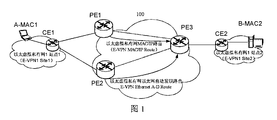
- network 100 network 100 includes a backbone network provided by a service provider and a plurality of E-VPN sites.
- the backbone network includes a first PE device PE1, a second PE device PE2, and a third PE device PE3, and a plurality of P (Provider) devices (not shown).
- the plurality of E-VPN sites include site1 and site2. Site1 and site2 belong to the same E-VPN1.
- Terminal device A with MAC address MAC1 is connected to CE1, and CE1 is dual-homed to PE1 and PE2.
- Terminal device B with MAC address MAC2 accesses CE2, and CE2 accesses PE3.
- PE1 learns the MAC address of the terminal device A from CE1.
- PE2 did not learn the MAC address of terminal device A from CE1.
- the PE1 sends an EVPN Media Access Control/Internet Protocol Advertisement (PE) message to the PE3 through the BGP Update (Update) message, that is, the MAC route to the terminal device A is advertised to the PE3.
- the PE2 can not discover the MAC1, but the PE2 can advertise the EPVN Ethernet auto-discovery route to the PE3.
- the PE3 can know that both the PE1 and the PE2 can reach the terminal device A, that is, the PE3 is based on the alias. Aliasing) forms a load sharing. It should be noted that, in FIG. 1, the terminal device A accesses the PE device through the CE1 as an example.
- the terminal device A can directly access the PE device as a CE device.
- the terminal device A The MAC address is the MAC address of the CE device.
- the terminal device A accesses the PE device through the CE device as an example.
- the scheme for the terminal device to directly access the PE device is similar to the solution for the terminal device to access the PE device through the CE device, and is not described here.
- PE1 and PE2 do not perform effective load sharing on the known unicast traffic with the destination MAC address being MAC1. It not only wastes the bandwidth resources of PE2 to CE1, but also consumes the bandwidth resources of PE1 to CE1. In the above solution, system resources are wasted, and the technical advantages of EVPN cannot be effectively utilized.
- the present invention provides a method for processing a packet, which is used to prevent a PE device from directly forwarding traffic to a CE device that is connected to the PE device, thereby preventing an effective load between multiple PE devices. Sharing technical issues.
- the present application provides a packet processing method, where the method is applied to an EVPN, where a user edge CE device is connected to a first interface of a first carrier edge PE device via a first link, the CE device Connected to the second interface of the second PE device via the second link.
- the first PE device generates a first message, where the first message carries a first MAC/IP Advertisement Route and a virtual local area network VLAN identifier that reach the CE device.
- the first MAC/IP Advertisement Route includes a MAC address and an Ethernet segment identifier ESI for identifying an Ethernet segment ES, where the MAC address included in the first MAC/IP Advertisement Route is a MAC address of the CE device or the MAC address of the terminal device under the jurisdiction of the CE device.
- the Ethernet segment ES includes the first link and the second link, and the VLAN identifier is used to indicate a VLAN to which the terminal device belongs.
- the first PE device sends the first message to the second PE device, where the first MAC/IP Advertisement Route and the VLAN identifier are used by the second PE device to generate a first MAC forwarding entry.
- the first MAC forwarding entry includes a MAC address included in the first MAC/IP Advertisement Route and the VLAN identifier; and the outbound interface identifier included in the first MAC forwarding entry is an identifier of the second interface.
- the first MAC forwarding entry is used by the second PE device to forward, to the CE device, a packet whose destination MAC address is a MAC address included in the first MAC/IP Advertisement Route.
- the first PE device notifies the second PE device of the MAC learned from the CE, if the second PE device does not learn the MAC route from the CE device, and cannot obtain the VLAN information to which the terminal device belongs. Routing and VLAN identification.
- the second PE device is configured to generate the first MAC forwarding entry according to the received MAC route and the VLAN identifier.
- the second PE device receives the data stream whose destination MAC address is the MAC address included in the first MAC/IP Advertisement Route, the second MAC device can directly go to the CE through the second link according to the first MAC forwarding entry. The device forwards the data stream.
- multiple PE devices can effectively form load sharing and implement reasonable utilization of bandwidth resources.
- the PE device can learn VLAN information from the CE through the control plane.
- the second PE device cannot directly learn the VLAN information from the CE device.
- the second PE device may learn the VLAN information from the first PE device. Further, the second PE device may forward traffic to the CE device according to the VLAN information.
- the CE device terminates access to the second PE device through the Ethernet tag tag or the Ethernet tag
- the second PE does not learn the VLAN information directly from the CE device, and the second PE device cannot obtain the VLAN information, so that the packet cannot be directly forwarded to the CE device.
- the first message is a first border gateway protocol update BGP Update message
- the first BGP Update message includes a VLAN attribute field for carrying the VLAN identifier.
- the VLAN attribute field includes a type (English: Type) field and a sub-type (English: Sub-Type) field, where the value of the Type field is used to identify a type of the multiplexed EVPN extended community attribute, the Sub-Type field.
- the value indicates that the extended community attribute is a VLAN extended community attribute.
- the VLAN attribute field further includes a VLAN value field for carrying the VLAN identifier.
- the present application can effectively utilize the existing protocol to implement VLAN information advertisement.
- the method further includes: the first PE device receiving the second PE device to send The second message.
- the second message carries a second MAC/IP Advertisement Route, a next hop network address, and the VLAN identifier.
- the second MAC/IP Advertisement Route includes a destination MAC address and the Ethernet segment identifier ESI; a destination MAC address in the second MAC/IP Advertisement Route and a MAC included in the first MAC/IP Advertisement Route
- the next hop network address carried by the second message is the network address of the second PE device, for example, a loopback loopback address of the second PE device.
- the Ethernet segment identifier ESI is used by the first PE device to determine that the interface of the first PE device connected to the CE device is the first interface.
- the determined first interface, the MAC address included in the second MAC/IP Advertisement Route, and the VLAN identifier are used by the first PE device to generate a second MAC forwarding entry.
- the second MAC forwarding entry includes a MAC address included in the second MAC/IP Advertisement Route, and the identifier of the outbound interface included in the second forwarding entry is an identifier of the first interface, and the second The MAC forwarding entry is used by the first PE device to forward an entry of a packet whose destination MAC address is a MAC address included in the second MAC/IP Advertisement Route.
- the method further includes: the first PE device generates a third MAC forwarding entry according to the MAC address included in the second MAC/IP Advertisement Route and the network address of the second PE device.
- the third MAC forwarding entry includes a MAC address included in the second MAC/IP Advertisement Route, and the third hop network address included in the third MAC forwarding entry is a network address of the second PE device.
- the third MAC forwarding entry is used by the first PE device to forward a packet whose destination MAC address is a MAC address included in the second MAC/IP Advertisement Route. The entry.
- the first PE device After the first PE device generates the third forwarding entry and the fourth forwarding entry, the first PE device implements fast weight according to the third MAC forwarding entry and the fourth MAC forwarding entry. Route the FRR.
- the first PE device receives the known unicast traffic (the destination MAC address carried in the data packet is the MAC address included in the second MAC/IP Advertisement Route), the first PE device queries the MAC forwarding table. When the first link is working normally, the packet is forwarded directly through the CE device according to the indication of the third MAC forwarding entry.
- the first PE device When the first link device is faulty, after the first PE device receives the known unicast traffic, the first PE device queries the MAC forwarding table, according to the indication of the standby forwarding entry, that is, the indication of the fourth MAC forwarding entry. And forwarding the traffic to the second PE device, and forwarding, by the second PE device, the traffic to the CE device, thereby improving a convergence speed of the fault.
- the second message also carries indication information.
- the method further includes: the first PE device avoiding sending the arrival to the second PE device according to the indication of the indication information The MAC/IP Advertisement Route of the MAC address included in the second MAC/IP Advertisement Route and the VLAN identifier. This can effectively avoid the formation of a message loop.
- the present application provides a packet processing method, which is applied to an EVPN, where a user edge CE device is connected to a first interface of a first carrier edge PE device via a first link, and the CE device is connected to the second device. The link is connected to the second interface of the second PE device.
- the second PE device receives the first message sent by the first PE device.
- the first message carries a first media access control/Internet Protocol advertisement routing MAC/IP Advertisement Route and a first VLAN identifier.
- the first MAC/IP Advertisement Route includes a MAC geology and an Ethernet segment identifier ESI for identifying an Ethernet segment ES, and the MAC address included in the first MAC/IP Advertisement Route is a MAC address or a location of the CE device.
- the MAC address of the terminal device under the jurisdiction of the CE device.
- the Ethernet segment ES includes the first link and the second link, and the first VLAN identifier is used to indicate a VLAN to which the terminal device belongs. Then, the second PE device determines, according to the Ethernet segment identifier ESI, that the interface that the second PE device connects to the CE device is the second interface.
- the second PE device generates a first MAC forwarding entry according to the determined second interface, the MAC address included in the first MAC/IP Advertisement Route, and the first VLAN identifier, where
- the first MAC forwarding entry includes the MAC address included in the first MAC/IP Advertisement Route and the first VLAN identifier, and the outbound interface identifier included in the first MAC forwarding entry is an identifier of the second interface.
- the first MAC forwarding entry is used by the second PE device to forward, to the CE device, the first VLAN identifier and the destination MAC address is a MAC included in the first MAC/IP Advertisement Route. Address message.
- the first PE device notifies the second PE device of the MAC route learned from the CE and the VLAN identifier.
- the second PE device is configured to generate the first MAC forwarding entry according to the received MAC route and the VLAN identifier.
- the second PE device receives the data stream whose destination MAC address is the MAC address included in the first MAC/IP Advertisement Route, the second MAC device can directly go to the CE through the second link according to the first MAC forwarding entry. The device forwards the data stream.
- the PE device can learn the VLAN information through the control plane.
- the second PE device cannot directly learn the VLAN information from the CE device.
- the second PE device may learn the VLAN information from the first PE device.
- the first PE device may forward the traffic reaching the terminal device to the CE device according to the VLAN information. For example, when the CE device terminates the access to the PE device through the Ethernet tag tag or the Ethernet tag, the first PE can forward the packet to the CE device according to the learned VLAN information.
- the first message further carries a next hop network address
- the next hop network address in the first message is a network address of the first PE device, for example, the The loopback lookback address of the first PE device.
- the method further includes: the second PE device acquiring a network address of the first PE device according to the first message; and the second PE device according to the first MAC/IP Advertisement
- the MAC address included in the route and the network address of the first PE device generate a second MAC forwarding entry.
- the second MAC forwarding entry includes a MAC address included in the first MAC/IP Advertisement Route, and the second MAC forwarding entry included in the second MAC forwarding entry is a network of the first PE device. address.
- the second link fails, the second MAC forwarding entry is used by the second PE to forward the first VLAN identifier and the destination MAC address is the first MAC/IP Advertisement Route.
- the message of the included MAC address is used by the second PE to forward the first VLAN identifier and the destination MAC
- the second PE device When the second PE device receives the known unicast traffic (the destination MAC address carried in the data packet is the MAC address included in the first MAC/IP Advertisement Route), the second PE device queries the MAC forwarding table. When the second link is in a normal working state, the packet is directly forwarded by the CE device by using the second link according to the indication of the first MAC forwarding entry. When the second link is faulty, the second PE device forwards the traffic to the first PE device according to the indication of the second MAC forwarding entry when receiving the foregoing known unicast traffic, by using the The first PE device forwards the traffic to the CE device, thereby improving the convergence speed of the fault. Further, in the EVPN, the PE device can learn VLAN information from the CE device through the control plane.
- the second PE device cannot directly learn the VLAN information from the CE device.
- the second PE device may learn the VLAN information from the first PE device. Further, the second PE device may forward traffic to the CE device according to the VLAN information. For example, when the CE device terminates the access to the PE device through the Ethernet tag tag or the Ethernet tag, the second PE device can forward the traffic to the CE device according to the VLAN information.
- the first message is a first border gateway protocol update BGP Update message
- the first BGP Update message includes a VLAN attribute field for carrying the first VLAN identifier.
- the present application can effectively utilize the existing protocol to implement VLAN information advertisement.
- the second PE device generates a first MAC address according to the determined second interface, the MAC address included in the first MAC/IP Advertisement Route, and the first VLAN identifier. After the item is published, the second PE device receives the first packet carrying the second VLAN identifier, and the destination MAC address of the first packet is the MAC address included in the first MAC/IP Advertisement Route. The second PE device replaces the second VLAN identifier carried in the second packet with the first VLAN identifier according to the first MAC forwarding entry, and obtains that the first VLAN identifier is carried by the second VLAN identifier. Second message. The second PE device sends the second packet to the CE device.
- the method further includes: the second PE device generates a second message, the second The message carries a second MAC/IP Advertisement Route, a next hop network address, and the first VLAN identifier.
- the second MAC/IP Advertisement Route includes a MAC address and the Ethernet segment identifier ESI.
- the second MAC/IP Advertisement Route includes a MAC address that is the same as the MAC address that is included in the first MAC/IP Advertisement Route, and the next hop network address that is carried by the second message is the second PE. The network address of the device.
- the second PE device sends the second message to the first PE device, where the second message is used by the first PE device to generate a third MAC forwarding entry and a fourth MAC forwarding entry.
- the third MAC forwarding entry is used by the first PE device to forward a packet whose destination MAC address is a MAC address included in the second MAC/IP Advertisement Route, and the third MAC forwarding entry Including the second MAC/IP And the identifier of the outbound interface that is included in the third MAC forwarding entry is the identifier of the first interface.
- the fourth MAC forwarding entry is used by the first PE device to forward a packet whose destination MAC address is a MAC address included in the second MAC/IP Advertisement Route.
- the fourth MAC forwarding entry includes a MAC address included in the second MAC/IP Advertisement Route, and the fourth forwarding network entry included in the fourth forwarding entry is a network address of the second PE device.
- the second PE device After receiving the first message, the second PE device generates a local primary MAC routing entry and a standby MAC routing table for fast rerouting on the control plane according to the information carried in the first message. Further, the control plane sends the foregoing primary MAC routing entry and the standby MAC routing entry to the forwarding plane, and generates a first MAC forwarding entry and a second MAC forwarding entry for implementing fast re-routing. And the second PE device, after receiving the first message, generates the local first MAC forwarding entry, and then sends the local MAC route back to the first PE device, so that the first PE device Generate an alternate MAC routing entry that is used to implement fast slave routes.
- the MAC route learned by the first PE device from the CE device can be used as a local MAC route, that is, a primary MAC route.
- a local MAC route that is, a primary MAC route.
- the local MAC route of the first PE device is revoked.
- the first PE device may generate the local MAC route again according to the second MAC/IP Advertisement Route and the first VLAN identifier advertised by the second PE device. Used to guide the forwarding of traffic to the CE device. Therefore, after the first link sends a fault and recovers again, the route redirection can be quickly implemented to achieve fast convergence of the fault.
- the local MAC address of the PE device in the present application refers to a route for directing unicast traffic to the CE device.
- the destination MAC address included in the local MAC route is the CE.
- the identifier of the outbound interface included in the local MAC address is the interface identifier of the CE device connected to the CE device.
- the second message further carries indication information, where the indication information is used to indicate that the first PE device avoids the second PE device after receiving the second message.
- the present application provides a first carrier edge PE device, the first PE device being configured to perform the method in the first aspect and any of the possible aspects of the first aspect.
- the first PE device comprises means for implementing the method of the first aspect and any of the possible designs of the first aspect.
- the present application provides a second carrier edge PE device, where the second PE device is configured to perform the method in any of the second aspect and the second aspect.
- a module for implementing the method of the second aspect and any of the possible designs of the second aspect is included.
- the application provides a first PE device, where the first PE device includes: an input interface, an output interface, a processor, and a memory. Wherein, the input interface, the output interface, the processor and the memory can be connected by a bus system.
- the memory is for storing a program for executing a program in the memory to perform the method of any of the first aspect or the first aspect of the first aspect.
- the application provides a second PE device, where the second PE device includes: an input interface, an output interface, a processor, and a memory. Wherein an input interface, an output interface, a processor, and the memory They can be connected by a bus system.
- the memory is for storing a program for executing a program in the memory to perform the method of any of the possible aspects of the second aspect or the second aspect.
- the embodiment of the present application provides a first PE device, where the first PE device includes: a main control board and an interface board, and further includes a switching network board.
- the first PE device is operative to perform the method of the first aspect or any possible design of the first aspect.
- the embodiment of the present application provides a first PE device, where the first PE device includes: a controller and a first PE forwarding device.
- the first PE forwarding device includes: an interface board, and further, a switching network board.
- the first PE device is operative to perform the method of the first aspect or any possible design of the first aspect.
- the controller includes a receiver, a processor, a transmitter, a random access memory, a read only memory, and a bus.
- the processor is coupled to the receiver, the transmitter, the random access memory, and the read only memory through a bus.
- the booting is started by the solid input/output system in the read-only memory or the bootloader booting system in the embedded system, and the controller is put into a normal running state. After the controller enters the normal operating state, the application and the operating system are run in the random access memory, so that the processor performs the functions of the main control board in the seventh aspect.
- the embodiment of the present application provides a second PE device, where the second PE device includes: a main control board and an interface board, and further includes a switching network board.
- the second PE device is operative to perform the method of any of the possible aspects of the second aspect or the second aspect.
- the embodiment of the present application provides a second PE device, where the second PE device includes: a controller and a second PE forwarding device.
- the second PE forwarding device includes: an interface board, and further, a switching network board.
- the second PE device is operative to perform the method of any of the possible aspects of the second aspect or the second aspect.
- the controller includes a receiver, a processor, a transmitter, a random access memory, a read only memory, and a bus.
- the processor is coupled to the receiver, the transmitter, the random access memory, and the read only memory through a bus.
- the booting is started by the solid input/output system in the read-only memory or the bootloader booting system in the embedded system, and the controller is put into a normal running state. After the controller enters the normal operating state, the application and the operating system are run in the random access memory, so that the processor performs the functions of the main control board in the seventh aspect.
- the embodiment of the present application provides a communication system, where the communication system includes the third aspect, the fifth aspect, the first PE device, the fourth aspect, and the sixth aspect.
- the second PE device of the ninth or eleventh aspect is provided.
- the embodiment of the present application provides a computer readable storage medium or computer program product for storing a computer program for performing the first aspect, the second aspect, and any possible design of the first aspect. Or the method of any of the possible aspects of the second aspect.
- the method, the device, and the system provided by the embodiments of the present application enable an effective load sharing between the PE devices connected to the CE device in the scenario that the CE device is connected to the PE device in the EVNP.
- System bandwidth resources are rationally utilized.
- FIG. 1 is a schematic diagram of an EVPN application scenario provided in the prior art
- FIG. 2 is a schematic diagram of an application network scenario of a packet processing method according to an embodiment of the present disclosure
- FIG. 3 is a schematic flowchart diagram of another packet processing method according to an embodiment of the present disclosure.
- 4a is a schematic diagram of a format of an MP_REACH_NLRI attribute field in a BGP Update message according to an embodiment of the present disclosure
- FIG. 4b is a schematic diagram of a format of an EVPN NLRI field according to an embodiment of the present application.
- 4c is a schematic diagram of a format of an EVPN MAC/IP Advertisement Route field according to an embodiment of the present application
- FIG. 4 is a schematic diagram of an ESI field format according to an embodiment of the present application.
- FIG. 5 is a schematic diagram of a format of a VLAN attribute field in a BGP Update message according to an embodiment of the present disclosure
- FIG. 6 is a schematic flowchart diagram of another packet processing method according to an embodiment of the present disclosure.
- FIG. 7 is a schematic flowchart diagram of another packet processing method according to an embodiment of the present disclosure.
- FIG. 8 is a schematic structural diagram of a first PE device according to an embodiment of the present disclosure.
- FIG. 9 is a schematic structural diagram of a second PE device according to an embodiment of the present disclosure.
- FIG. 10 is a schematic structural diagram of hardware of a first PE device according to an embodiment of the present disclosure.
- FIG. 11 is a schematic structural diagram of hardware of a second PE device according to an embodiment of the present disclosure.
- FIG. 12 is a schematic structural diagram of a first PE device according to an embodiment of the present disclosure.
- FIG. 13 is a schematic structural diagram of a first PE device according to an embodiment of the present disclosure.
- FIG. 14 is a schematic structural diagram of a second PE device according to an embodiment of the present disclosure.
- FIG. 15 is a schematic structural diagram of a second PE device according to an embodiment of the present disclosure.
- the technical solution described in this application can be applied to BGP MPLS-based EVPN.
- the EVPN technology adopts a mechanism similar to the BGP/MPLS Internet Protocol (IP) VPN.
- IP Internet Protocol
- the MAC address learning and distribution between Layer 2 networks at different sites is enabled.
- the process moves from the data plane to the control plane.
- the function of L2VPN is realized by learning the MAC address in the control plane. Learning the MAC address on the control plane can solve the problem that the multi-homing of network devices is difficult to implement and the load balancing cannot be supported.
- Multi-homing access to the EVPN of the CE device includes multiple access to the EVPN through the Ethernet link.
- the deployment of a CE device to multiple network-side devices through multiple links is called CE device multi-homing access.
- FIG. 2 shows a typical Ethernet link multi-homing multiple access EVPN scenario.
- the EVPN includes four PEs, namely PE1-1, PE1-2, PE1-3, and PE2.
- CE1 is connected to PE1-1, PE1-2, and PE1-3 through Ethernet links (English: Ethernet Link, EL) 1, EL2, and EL3.
- a group of Ethernet links containing these three Ethernet links is an Ethernet segment (English: Ethernet Segment, ES).
- the Ethernet Segment Identifier (ESI) is a unique non-zero identifier. Used to identify the Ethernet segment ES.
- PE1-1 learns the MAC address of the user equipment (English: User Equipment, UE) 1 in the site of the VPN1 (English: site) 1. For example, MAC A, PE1-1 advertises the MAC/IP advertisement route to PE2 through the BGP Update message. . PE1-2 did not learn the MAC address of UE1. PE1-2 advertises Ethernet auto-discovery route (Ethernet A-D route) to PE2. Therefore, PE2 knows according to the alias (English: Aliasing), PE2 can reach UE1 via PE1-1, and PE2 can reach UE1 via PE1-2. Therefore, when the unicast traffic sent by the UE2 to the UE1 is transmitted through the PE2, the PE2 can perform load sharing processing on the unicast traffic. The unicast traffic is forwarded to CE1 via PE1-1 and PE1-2. Thereby, the interworking of UE1 and UE2 in VPN1 is implemented.
- alias English: Aliasing
- EVPN supports multiple redundancy modes.
- the multiple redundancy modes include a single-active redundancy mode, a multi-active redundancy mode, and a full-lived redundancy mode.
- the so-called single-active redundancy mode (referred to as single-active mode) means that only one Ethernet link in the Ethernet link segment is active, and the other one or more Ethernet links are inactive.
- the active state means that the Ethernet link can be used to carry and forward data streams. In the scenario of active/standby protection, it is usually used as the primary Ethernet link.
- the state of the Ethernet link can also be inactive.
- the inactive state means that the Ethernet link cannot be used to carry and forward data streams, and is usually used as a backup Ethernet link.
- the deployment scenario in single-live mode can include single-live (only one EL in the ES), single-active single-standby (two ELs in the ES, one active state, the other active state), and single live Multiple standby (there are at least three ELs in the ES, one state is active, and at least two states are inactive). Further explained in conjunction with FIG. 2, if only one Ethernet link EL1 in the ES is active, used as the primary EL, and the other EL2 and EL3 are inactive, used as the backup EL, the redundant mode is single-lived. Double standby (belonging to single live and multiple standby).
- the all-lived redundancy mode (referred to as the full-active mode) means that the status of all Ethernet links in the Ethernet link segment is active, that is, there is no inactive. State Ethernet link. All of these active Ethernet links enable load-sharing forwarding of data streams, providing greater bandwidth transmission capabilities.
- the full-live mode scenario does not support backup, that is, there is no backup Ethernet link. When one or more Ethernet links of the primary device fail, it cannot be switched to the standby Ethernet link for redundancy protection. As further explained in connection with FIG. 2, if all three Ethernet links EL1, EL2, and EL3 in the ES are active, then there is no backup EL, then the redundancy mode is the full live mode.
- the so-called multi-active redundancy mode means that the status of some Ethernet links in the Ethernet link segment is active, and another part of the Ethernet chain is active. The state of the road is inactive.
- These active Ethernet links (used as primary Ethernet links) enable load-sharing forwarding of data streams, providing greater bandwidth transmission capabilities.
- Another part of the inactive Ethernet link is used as a backup. When one or more Ethernet links of the primary device fail, they can be switched to these alternate Ethernet links for redundancy protection. Further explained in conjunction with FIG. 2, if two Ethernet links EL1 and EL2 in the ES are active and EL3 is inactive, EL1 and EL2 are combined to perform load sharing forwarding on the data stream, and EL3 is EL1 or EL2 provides backup protection.
- the traffic sent by the CE device to the PE device is routed through a hash (English: Hash) algorithm.
- the specific implementation of the Hash algorithm depends on the CE device.
- the implementation of the CE device does not guarantee that traffic will flow through each link between the CE device and the PE device.
- the PE device corresponding to the link cannot learn the MAC address of the terminal device that is connected to the CE device, and cannot obtain the VLAN information of the terminal device.
- the CE device uses the source MAC address and the destination MAC address as the hash factor
- the traffic sent by the CE to the PE device may be hashed to the link connected to PE1-1.
- PE1-2 does not learn UE1.
- the MAC address of the MAC address does not reach the local MAC forwarding entry of the UE1 on the PE1-2.
- the PE1-2 cannot directly forward the unicast traffic to the CE1.
- FIG. 2 shows that the terminal device accesses the PE device through the CE device.
- the terminal device itself can access the PE device as a CE device.
- the MAC address of the terminal device is the MAC address of the CE device. address.
- the scene shown in Figure 2 can be referenced in a variety of scenarios. For example, it is applied to a mobile bearer network (English: Mobile Bearer Network).
- a typical mobile bearer network is an Internet Protocol Radio Access Network (IP: RAN).
- IP Internet Protocol Radio Access Network
- the CE device may be a base station (English: Base Transceiver Station, abbreviated as: BTS), and the PE device may be connected to a base station controller (English: Base Station Controller, abbreviation: BSC) or a radio network controller. (English: Radio Network Controller, abbreviation: RNC).
- BTS Base Transceiver Station
- RNC Radio Network Controller
- the EVPN VXLAN is applied to a fixed network (English: Fixed Network).
- the CE device may be a user-side site, and the PE device may be a broadband access server (Broadband Access Server, abbreviated as BAS).
- BAS Broadband Access Server
- the CE device and the PE device in the embodiment of the present application may be corresponding devices defined in RFC7432.
- the PE device can be a router or a switch.
- the CE device may be a router or a switch or a terminal device.
- a CE device is connected to the PE device on one side and the UE is connected to the UE on the other side.
- the UE is also called a terminal device (English: Terminal Equipment, TE) or a terminal (English: terminal), and may be a handheld device with a wireless communication function, an in-vehicle device, a wearable device, a computer device, a virtual machine, or a connection to a wireless modem. Other processing equipment.
- the UE can also be a user equipment or a mobile station (English: Mobile Station, MS).
- PE and PE devices have the same meaning in various embodiments of the present application.
- CE and CE devices have the same meaning.
- the data stream described in this application may be a unicast data stream of known MAC address.
- FIG. 3 shows a packet processing method 300 provided by the present application, which is applied to an EVPN, and the user edge CE device accesses the scenario of at least two PE devices through at least two links.
- the at least two links form an Ethernet segment, and the at least two PE devices include a first PE device and a second PE device.
- the link may be an Ethernet link; and the identifier used to identify the Ethernet segment is an Ethernet segment identifier ESI.
- the Ethernet segment can also be referred to as an Ethernet link segment or a collection of Ethernet links.
- the CE device accesses the first interface of the first PE device via the first link.
- the CE device accesses the second interface of the second PE device via the second link.
- the Ethernet segment includes the first link and the second link.
- the method 300 shown in FIG. 3 can be applied to the scene shown in FIG. 2.
- the CE device may be, for example, the CE1 shown in FIG. 2
- the first PE device may be, for example, the PE1-1 shown in FIG. 2
- the second PE device may be, for example, the PE1 shown in FIG. -2.
- the method 300 includes S301 through S305.
- the first PE device generates a first message.
- the first message carries, the first media access control/Internet Protocol advertisement routing MAC/IP Advertisement Route, and the first VLAN identifier.
- the first MAC/IP Advertisement Route includes a MAC address and a link Ethernet segment identifier ESI for identifying an Ethernet segment ES, and the MAC address included in the first MAC/IP Advertisement Route is a MAC address of the CE device. Or the MAC address of the terminal device under the jurisdiction of the CE device.
- the first VLAN identifier is used to identify a VLAN to which the MAC address included in the first MAC/IP Advertisement Route belongs.
- the first message further includes a next hop network address, where the next hop network address is a network address of the first PE device, for example, a loopback address of the first PE device.
- the loopback address described in this application is an IP address configured on a loopback interface of a network device (such as a router, a switch, etc.), and is usually used as a network device identifier (for example, an IPv4 address of a 32-bit mask). : 10.10.1.1/32), which can be understood by those skilled in the art.
- the first PE device receives, from the first interface, a packet sent by the CE device by using the first link, where the packet carries a MAC address of the CE device. Or the MAC address of the terminal device that accesses the CE device and the first VLAN identifier, where the first PE device obtains the MAC address included in the first MAC/IP Advertisement Route from the packet, and the The first VLAN ID.
- the first PE device determines the Ethernet segment identifier ESI according to the first interface.
- the first PE device may include multiple interfaces.
- the plurality of interfaces may be a plurality of Ethernet interfaces.
- the first PE device may save configuration information of each interface of the first PE device.
- the configuration information of the first interface includes the ESI. That is, the first interface has a corresponding relationship with the ESI.
- the first PE device may determine the ESI according to a correspondence between the first interface and the ESI.
- the first PE device sends the first message to the second PE device.
- the first PE device sends the first message to the second PE device, where the first MAC/IP Advertisement Route and the first VLAN identifier are used by the second PE device to generate a first message.
- a MAC forwarding entry includes the MAC address included in the first MAC/IP Advertisement Route and the first VLAN identifier, and the outbound interface identifier included in the first MAC forwarding entry is the second interface
- the first MAC forwarding entry is used by the second PE device to forward, to the CE device, a packet whose destination MAC address is a MAC address included in the first MAC/IP Advertisement Route.
- the first PE device can learn the MAC address included in the first MAC/IP Advertisement Route from the CE device, and the second PE device cannot be from the CE.
- the device learns the MAC address included in the first MAC/IP Advertisement Route.
- the first message is a Border Gateway Protocol (BGP) update (English: Update) message (also referred to as a BGP Update message).
- BGP Update message is referred to as a first BGP Update message.
- the first BGP Update message carries the MAC/IP Advertisement Route and the first VLAN identifier.
- the MAC/IP Advertisement Route carried in the first BGP Update message is referred to as a first MAC/IP Advertisement Route.
- the MAC/IP Advertisement Route belongs to the reachable layer information of the EVPN network defined by the BGP protocol.
- a route type in Network Layer Reachability Information (NLRI) that guides unicast traffic forwarding.
- the EVPN NLRI is carried in the Multiprotocol Reachable NLRI (MP_REACH_NLRI) attribute.
- the MP_REACH_NLRI attribute is an attribute defined in the BGP Update message. The format is as shown in Figure 4a.
- the attribute includes the Address Family Identifier (AFI) field and the Subsequent Address Family Identifier (SAFI). Field.
- AFI Address Family Identifier
- SAFI Subsequent Address Family Identifier
- the value of the AFI field is used to indicate L2VPN, such as 25.
- the value of the SAFI field is used to indicate EVPN, such as 70.
- the MP_REACH_NLRI attribute also includes a Length of Next Hop Network Address and a Network Address of Next Hop field.
- the next hop network address field is used to carry the next hop network address (such as a loopback address).
- the MP_REACH_NLRI attribute further includes an NLRI field, and the value of the AFI and the SAFI is used to indicate an EVPN in the L2VPN, and the NLRI field is an EVPN NLRI field.
- the EVPN NLRI field includes, for example, a 2-byte route type (English: Route Type) field, a 2-byte length (English: Length) field, and a variable-length route type detail (English: Route) Type specific) field.
- the Route Type includes the MAC/IP Advertisement Route, for example, the value is 2.
- the Route Type specific field is used to carry the details of the MAC/IP Advertisement Route. As shown in FIG.
- the MAC/IP Advertisement Route includes an 8-byte route distinguisher (English: Route Distinguisher, RD) field, a 10-byte Ethernet segment identifier (English: Ethernet Segment Identifier, ESI) field, and 4 Byte Ethernet tag identifier (English: Ethernet Tag ID) field, 1 byte MAC address length field, 6 byte MAC address field, 1 byte next hop network address length field, 0 word Section or 4-byte or 16-byte next hop network address field, 3-byte MPLS label 1 (English: Label) field, and 0-byte or 3-byte MPLS label 2 field, MPLS label 2 is used to guide Layer 3 traffic forwarding.
- route distinguisher English: Route Distinguisher, RD
- Ethernet segment identifier English: Ethernet Segment Identifier, ESI
- 4 Byte Ethernet tag identifier (English: Ethernet Tag ID) field
- 1 byte MAC address length field 6 byte MAC address field
- 1 byte next hop network address length field 1 byte next hop network address length field
- the format of the ESI field shown in Figure 4c is as shown in Figure 4d, including the Type (English: Type, T) field and the ESI Value (English: Value) field.
- the Type field is used to indicate how ESI is generated.
- the two commonly used generation methods are Type0 and Type1, where Type0 indicates that the configuration is manually configured.
- Type1 indicates that the link aggregation control protocol (LAC: Link Aggregation Control Protocol, LACP) is used between the PE and the CE.
- LAC Link Aggregation Control Protocol
- the value ranges from 0 to 0xFF, where "0x" means hexadecimal.
- the generation and setup of ES and ESI can be found in Chapter 5 of RFC7432.
- For the definition of the EVPN NLRI field refer to the description in RFC7432.
- the application extends the BGP protocol to add a VLAN attribute, and carries the VLAN identifier through a VLAN attribute.
- the specific format of the VLAN attribute is shown in FIG. 5.
- the VLAN attribute includes a type (English: Type) field and a subtype (English: Sub-Type) field.
- the value of the Type field is used to identify the type of the multiplexed EVPN extended community attribute.
- the value is OX06.
- the value of the Sub-Type field indicates that the extended community attribute is a VLAN extended community attribute, and the value is, for example, Oxcc.
- the values of the Type field and the Sub-Type field are only examples. The actual value is based on the value assigned by the Internet Assigned Numbers Authority (IANA).
- the VLAN attribute also includes a reserved (English: Reserved) field, which is padded to 0 when not in use.
- the VLAN attribute also includes a VLAN value field, and the length of the VLAN Value field is, for example, 4 bytes, and is used to carry a VLAN identifier.
- the The VLAN Value field includes a Service VLAN (S-VLAN) field and a Customer VLAN (C-VLAN) field.
- S-VLAN field is used to carry the S-VLAN identifier and cannot be 0.
- the C-VLAN field is used to carry the C-VLAN identifier. When the value is 0, it indicates that there is no C-VLAN. When the value is non-zero, it is used to indicate the C-VLAN identifier.
- the length of the Type field and the Sub-Type field may be, for example, 1 byte, and the length of the Reserved field may be 2 bytes, for example, the length of the S-VLAN field and the C-VLAN field may be 2, for example. Bytes, which are not specifically limited in this application.
- the second PE device receives the first message sent by the first PE device.
- the second PE device determines that the interface that connects the CE device is the second interface.
- the interface for connecting the CE device is configured with the same Ethernet segment identifier ESI.
- the CE device is connected to the first PE device and the second PE device through multiple E-TRUNK connections.
- the CE device is equivalent to a PE device.
- the first PE device and the second PE device have multiple interfaces, and the first PE device is connected to the CE device through the first interface, and the second PE device is connected to the CE device through the second interface.
- the configuration information of the first interface is saved on the first PE device.
- the configuration information of the second interface is saved on the second PE device.
- the configuration information of the first interface includes an ESI.
- the configuration information of the second interface includes ESI.
- the ESI configured for the first interface is the same as the ESI configured for the second interface. Therefore, after the second PE device receives the first message, the first MAC/IP Advertisement Route carried in the first message is obtained.
- the second PE device extracts the Ethernet segment identifier ESI carried in the first MAC/IP Advertisement Route to obtain the Ethernet segment identifier ESI.
- the second PE device determines, according to the ESI, an interface that connects the CE device to the second interface.
- the second PE device may include multiple interfaces.
- the plurality of interfaces may be a plurality of Ethernet interfaces.
- the second PE device may save configuration information of each interface of the second PE device.
- the configuration information of the second interface includes the ESI.
- the second interface has a corresponding relationship with the ESI.
- the second PE device may search for the ESI that includes the ESI in the configuration information of the multiple interfaces that are saved by the second PE device by using the ESI that is carried in the first MAC/IP Advertisement Route as a search key. Configuration information.
- the second PE device finds the configuration information that includes the ESI, the second PE device may determine, according to the correspondence between the second interface and the ESI, that the second PE device connects to the CE device.
- the interface is the second interface.
- the second PE device generates a first MAC forwarding entry.
- the second PE device generates a first MAC forwarding entry according to the determined second interface, the MAC address included in the first MAC/IP Advertisement Route, and the first VLAN identifier.
- the first MAC forwarding entry is used by the second PE device to forward, to the CE device, a packet whose destination MAC address is a MAC address included in the first MAC/IP Advertisement Route.
- the first MAC forwarding entry includes the MAC address included in the first MAC/IP Advertisement Route and the first VLAN identifier, and the outbound interface identifier included in the first MAC forwarding entry is the second interface Logo.
- the packet in the data stream is determined from the determined The second interface forwards to the CE device.
- the CE device accesses the first PE device and the second PE device by using an Ethernet tag, an Ethernet tag termination, or an 802.1Q nested 802.1Q (QinQ).
- Receiving, by the second PE device, the first packet carrying the second VLAN identifier, where the destination MAC address of the first packet is the first MAC/IP The MAC address included in the Advertisement Route.
- the second PE device determines that the second interface is an outbound interface for forwarding the first packet by searching the first MAC forwarding entry.
- the second PE device searches for the first VLAN identifier associated with the MAC address in the first MAC forwarding entry by using the carried MAC address in the first packet as a key, and the first packet
- the second VLAN identifier is replaced with the first VLAN identifier, and after all the forwarding processing actions are completed, the second packet encapsulated with the first VLAN identifier is obtained, and the second packet is passed through the second packet.
- the interface forwards to the CE device.
- the first VLAN identifier may include only a single VLAN identifier (English: Indentifier, ID) It can also include multiple VLAN IDs.
- the second VLAN identifier may include only a single VLAN ID, and may also include multiple VLAN IDs.
- the specific form of the first VLAN identifier and the second VLAN identifier is not specifically limited in this application.
- the first PE device notifies the second PE device to learn from the CE device that the second PE device does not learn the MAC route from the CE device and cannot obtain the valid VLAN information. MAC route and the VLAN identifier.
- the second PE device is configured to generate the first MAC forwarding entry according to the received MAC route and the VLAN identifier.
- the second PE device receives the data stream whose destination MAC address is the MAC address included in the first MAC/IP Advertisement Route
- the second MAC device can directly go to the CE through the second link according to the first MAC forwarding entry. The device forwards the data stream.
- the PE device can learn the VLAN identifier through the control plane.
- the second PE device cannot directly learn the VLAN identifier from the CE device.
- the second PE device may learn the VLAN identifier from the first PE device.
- the second PE device may forward traffic to the CE device according to the VLAN identifier. For example, when the CE device terminates access to the second PE device through the Ethernet tag tag or the Ethernet tag, the traffic is forwarded to the CE device according to the VLAN identifier.
- the method 300 may further include S306-308. As shown in FIG. 6, the method 300 includes S301-S308.
- the second PE device acquires and obtains a next hop network address carried in the first message.
- next hop network address may be referred to as a first next hop network address
- first next hop network address is a network address of the first PE device, for example, for the first PE device. Loopback address.
- the second PE device generates a second MAC forwarding entry.
- the second PE device generates the second MAC forwarding entry according to the MAC address included in the first MAC/IP Advertisement Route and the network address of the first PE device.
- the second MAC forwarding entry includes a MAC address included in the first MAC/IP Advertisement Route, and the second hop network address included in the second MAC forwarding entry is a network address of the first PE device.
- the second PE device receives the first message sent by the first PE device from a third interface Intf1, and the second PE device uses the first PE device as a destination The next hop node of the terminal device.
- the control plane for example, the control board
- the control plane of the second PE device generates a MAC routing entry (as shown in Table 1), and the destination MAC address of the MAC routing entry is the MAC included in the first MAC/IP Advertisement Route.
- the address, the next hop network address is the loopback address of the first PE device.
- the second The PE device generates the second MAC forwarding entry according to the MAC routing entry, as shown in Table 2, and sends the second MAC forwarding entry to the forwarding plane of the second PE device (for example, a forwarding board). .
- the second PE device may determine, according to the MAC routing entry, the purpose in the second MAC forwarding entry. MAC address and outgoing interface.
- the destination MAC address of the MAC forwarding entry is the destination address in the MAC routing entry (ie, the MAC address of the UE1).
- the outbound interface of the MAC forwarding entry is Intf1.
- the determining, by the second PE device, the outbound interface in the second MAC forwarding entry may include: first, the second PE device searches for a loopback address of the first PE device in the MAC routing entry.
- the keyword the Forwarding Equivalence Class (FEC) to the Next Hop Label Forwarding Entry (NHLFE) mapping table (also referred to as the FTN mapping table or the FTN forwarding table).
- FEC Forwarding Equivalence Class
- NHSFE Next Hop Label Forwarding Entry
- the tunnel identifier corresponding to the loopback address of the first PE device as the tunnel identifier of the tunnel of the second PE device to the first PE device (English: Tunnel Identifier, Tunnel ID); and then using the tunnel ID to find the tunnel forwarding table,
- the outbound interface corresponding to the tunnel ID is Intf 1 (that is, the interface of the second PE device to the tunnel of the first PE device on the second PE device).
- the second PE device determines the Intf1 as an outbound interface in the second MAC forwarding entry.
- the tunnel may be a Label Switched Path (LSP) tunnel, or may be a Resource Reservation Protocol-Traffic Engineering (RSVP-TE) tunnel.
- LSP Label Switched Path
- RSVP-TE Resource Reservation Protocol-Traffic Engineering
- Table 2 MAC forwarding table
- the second PE device implements fast rerouting (FRR) according to the first MAC forwarding entry and the second MAC forwarding entry.
- FRR fast rerouting
- the second PE device When the second PE device receives the known unicast traffic (the destination MAC address carried in the data packet is the MAC address included in the first MAC/IP Advertisement Route), the second PE device queries the MAC forwarding table. When the second link is in a normal working state, according to the indication of the first MAC forwarding entry, directly forwards the packet to the terminal device through the CE device via the second link; when the second link When the second PE device receives the known unicast traffic, the second PE device forwards the traffic to the first PE device according to the indication of the second MAC forwarding entry, and the first PE device sends the traffic to the first PE device. The CE device forwards the traffic, thereby improving the convergence speed of the fault.
- the method 300 may further include S309-S312.
- the method 300 is described below in conjunction with FIG. 7.
- the second PE device generates a second message.
- the second PE device After the second PE device receives the first message sent by the first PE device, the second PE device generates the second message. Specifically, the second PE device generates the second message according to the first message.
- the second message is used to carry a second MAC/IP Advertisement Route, a next hop network address and the first VLAN identifier, and the second MAC/IP Advertisement Route includes a MAC address and the Ethernet segment identifier ESI.
- the second MAC/IP Advertisement Route includes the MAC address that is the same as the MAC address that is included in the first MAC/IP Advertisement Route.
- the second PE device obtains the The MAC address included in the first MAC/IP Advertisement Route is encapsulated into the second MAC/IP Advertisement Route carried by the second message.
- the next hop network address carried by the second message is a network address of the second PE device, for example, a loopback address of the second PE device.
- the second PE device sends the second message to the first PE device.
- the second message is a BGP Update message.
- the BGP Update message is referred to as a second BGP Update message.
- the second BGP Update message carries the second MAC/IP Advertisement Route.
- the second BGP Update message includes a VLAN attribute field, which is used to carry the first VLAN identifier.
- the specific format of the second BGP Update message, the specific format of the second MAC/IP Advertisement Route, and the specific format of the VLAN attribute carrying the first VLAN identifier refer to the specific format of the first BGP Update message in S202.
- the specific format of the first MAC/IP Advertisement Route and the specific description of the VLAN attribute carrying the first VLAN identifier are not described herein again.
- the second message further includes indication information, where the indication information is used to indicate that the first PE device avoids the second PE device after receiving the second message.
- the second message includes a flag field for carrying the indication information.
- a flag field is set in the VLAN attribute field, and is used to carry the indication information.
- the length of the Flag field may be, for example, one bit or one byte, which is not limited in this application.
- a new field may be defined in the second message, for example, a Flag field, which is used to carry the indication information, and is not specifically limited.
- the first PE device receives the second message sent by the second PE device.
- the first PE device generates a third MAC forwarding entry and a fourth MAC forwarding entry.
- the second message carries the first VLAN identifier, and after the first PE device receives the second message, according to the second MAC/ carried in the second message.
- the MAC address included in the IP Advertisement Route, the Ethernet segment identifier ESI and the first VLAN identifier, and a third MAC forwarding entry is generated.
- the third MAC forwarding entry is used by the first PE device to forward a packet whose destination MAC address is a MAC address included in the second MAC/IP Advertisement Route, where the third MAC forwarding entry includes
- the identifier of the outbound interface is an identifier of the first interface.
- the manner in which the first PE device generates the third MAC forwarding entry is similar to the manner in which the second PE device generates the first MAC forwarding entry in the foregoing S305. For details, refer to S305, and details are not described herein again.
- the third MAC forwarding entry may be generated in the following scenarios:
- Scenario 1 The local MAC address of the first PE device does not reach the local MAC address of the terminal device. For example, the link between the first PE device and the CE device is faulty. The route was revoked. The first PE device may generate the third MAC forwarding entry according to the MAC address included in the second MAC/IP Advertisement Route carried by the first PE device and the Ethernet segment identifier ESI.
- Scenario 2 When the first PE device receives the second message, the first PE device has a local MAC address that reaches the MAC address included in the second MAC/IP Advertisement Route, and the first PE device saves the location.
- the routing information carried in the second message When the link between the first PE device and the CE device is faulty, and the local MAC route saved by the first PE device is revoked, the first PE device according to the routing information carried in the second message, that is, The MAC address included in the second MAC/IP Advertisement Route and the Ethernet segment identifier ESI are generated to generate the third MAC forwarding entry.
- the first PE device generates a fourth MAC forwarding entry according to the destination MAC address and the network address of the second PE device, where the fourth MAC forwarding entry is used to forward the destination MAC address.
- the manner in which the first PE device generates the fourth MAC forwarding entry is similar to the manner in which the second PE device generates the second MAC forwarding entry in the foregoing S307. For specific description, refer to S307. Let me repeat.
- the fourth MAC forwarding entry implement fast re-routing FRR.
- the first PE device receives the known unicast traffic (the destination MAC address carried in the data packet is the MAC address included in the second MAC/IP Advertisement Route), the first method is performed.
- the PE device queries the MAC forwarding table.
- the local MAC forwarding entry is also referred to as a fifth MAC forwarding entry.
- the fifth MAC forwarding entry may be, for example, the third MAC forwarding.
- the first PE device When the first link device is faulty, after the first PE device receives the known unicast traffic, the first PE device queries the MAC forwarding table, according to the indication of the standby forwarding entry, that is, the indication of the fourth MAC forwarding entry. And forwarding the traffic to the second PE device, and forwarding, by the second PE device, the traffic to the CE device, thereby improving a convergence speed of the fault.
- S306-S308 and S309-S312 may be included at the same time, and the execution order of S306-S308 and S309-S312 is in no particular order.
- the first PE device may The second PE device sends a MAC route revocation message to revoke the first MAC/IP Advertisement Route.
- the second PE device After receiving the MAC route revocation message sent by the first PE device, the second PE device does not immediately delete the first MAC/IP Advertisement Route, but starts the aging timer to reach the aging set by the aging timer. After the time, if the updated MAC route to the CE device is not received, the first MAC/IP is deleted. Advertisement Route.
- the second PE device After receiving the MAC route revocation message sent by the first PE device, the second PE device sends a MAC route revocation message to the remote PE device, for example, the third PE device PE2 shown in FIG. 2, As a result, the local MAC address of the first PE device is revoked due to the interface failure. After the remote MAC address is revoked by the second PE device, the first PE device does not reach the MAC route of the CE device. At this time, if the traffic sent by the PE2 reaches the first PE device, the first PE device cannot query the MAC forwarding table and cannot forward the traffic.
- FIG. 8 is a schematic diagram of a first PE device 400 according to an embodiment of the present application.
- the first PE device 400 can be PE1-1 in FIG. 2 and can be used to perform the method shown in FIG. 3, FIG. 6, or FIG.
- the user edge CE device is connected to the first interface of the first PE device via a first link, and the CE device is connected to the second interface of the second PE device via a second link.
- the first PE device 400 includes a processing module 401 and a sending module 402.
- the processing module 401 is configured to generate a first message, where the first message carries a first media access control/Internet Protocol advertisement routing MAC/IP Advertisement Route and a virtual local area network VLAN identifier, where the first MAC/IP Advertisement Route includes a MAC An address and an Ethernet segment identifier ESI for identifying an Ethernet segment ES, where the MAC address included in the first MAC/IP Advertisement Route is a MAC address of the CE device or a MAC address of a terminal device under the jurisdiction of the CE device.
- the Ethernet segment ES includes the first link and the second link, and the VLAN identifier is used to indicate a VLAN to which the MAC address included in the first MAC/IP Advertisement Route belongs.
- the sending module 402 is configured to send the first message to the second PE device.
- the first MAC/IP Advertisement Route and the VLAN identifier are used by the second PE device to generate a first MAC forwarding entry, where the first MAC forwarding entry includes the first MAC/IP Advertisement Route
- the included MAC address and the VLAN identifier, the outbound interface identifier included in the first MAC forwarding entry is an identifier of the second interface, and the first MAC forwarding entry is used by the second PE device
- the CE device forwards the packet whose destination MAC address is the MAC address included in the first MAC/IP Advertisement Route.
- the first PE device notifies the second PE device of the MAC route learned from the CE device, if the second PE device does not learn the MAC route from the CE device and cannot obtain the valid VLAN information. And the VLAN identifier.
- the second PE device is configured to generate the first MAC forwarding entry according to the received MAC route and the VLAN identifier.
- the second PE device receives the data stream whose destination MAC address is the MAC address included in the first MAC/IP Advertisement Route
- the second MAC device can directly go to the CE through the second link according to the first MAC forwarding entry.
- the device forwards the data stream.
- the CE device forwards the data stream to the terminal device.
- the PE device can learn the VLAN identifier through the control plane.
- the second PE device cannot directly learn the VLAN identifier from the CE device.
- the second PE device may learn the VLAN identifier from the first PE device.
- the second PE device may forward traffic to the CE device according to the VLAN identifier. For example, on a CE device through an Ethernet label When the tag or the Ethernet tag is terminated to access the second PE device, the second PE may forward the traffic to the CE device according to the VLAN identifier.
- the first message is a first border gateway protocol update BGP Update message
- the first BGP Update message includes a VLAN attribute field for carrying the VLAN identifier.
- the specific format of the first BGP Update message and the format of the VLAN attribute field (such as which fields or extension fields are used), refer to the description of the corresponding part in the foregoing method embodiment, and details are not described herein again.
- the present application can effectively utilize the existing protocol to implement VLAN information advertisement.
- the first PE device 400 further includes a receiving module 403.
- the receiving module 403 is configured to receive the second message sent by the second PE device.
- the second message carries a second MAC/IP Advertisement Route, a next hop network address, and the VLAN identifier.
- the second MAC/IP Advertisement Route includes a destination MAC address and the Ethernet segment identifier ESI; a destination MAC address in the second MAC/IP Advertisement Route and a MAC included in the first MAC/IP Advertisement Route
- the next hop network address carried by the second message is the network address of the second PE device.
- the Ethernet segment identifier ESI is used by the first PE device to determine that the interface of the first PE device connected to the CE device is the first interface.
- the determined first interface, the MAC address included in the second MAC/IP Advertisement Route, and the VLAN identifier are used by the first PE device to generate a second MAC forwarding entry, and the second MAC forwarding
- the publication item includes a MAC address included in the second MAC/IP Advertisement Route, and the identifier of the outbound interface included in the second forwarding entry is an identifier of the first interface, and the second MAC forwarding entry is
- the first PE device is configured to forward an entry of a packet whose destination MAC address is a MAC address included in the second MAC/IP Advertisement Route.
- the processing module 401 is further configured to generate a third MAC forwarding entry according to the MAC address included in the second MAC/IP Advertisement Route and the network address of the second PE device.
- the third MAC forwarding entry includes a MAC address included in the second MAC/IP Advertisement Route, and the next hop network address included in the third MAC forwarding entry is a network address of the second PE device.
- the third MAC forwarding entry is used by the first PE device to forward a packet whose destination MAC address is a MAC address included in the second MAC/IP Advertisement Route. The entry.
- the fast forwarding FRR is implemented according to the third MAC forwarding entry and the fourth MAC forwarding entry.
- the first PE device receives the known unicast traffic (the destination MAC address carried in the data packet is the second MAC/IP Advertisement Route including the MAC address)
- the first PE device queries the MAC forwarding table, when the first When the link is working normally, the packet is directly forwarded to the terminal device by using the CE device according to the indication of the third MAC forwarding entry.
- the first PE device When the first link device is faulty, after the first PE device receives the known unicast traffic, the first PE device queries the MAC forwarding table, according to the indication of the standby forwarding entry, that is, the indication of the fourth MAC forwarding entry. And forwarding the traffic to the second PE device, and forwarding, by the second PE device, the traffic to the CE device, thereby improving a convergence speed of the fault.
- the second message further carries indication information.
- the processing module 503 is further configured to: after the receiving module receives the second message sent by the second PE device, according to the indication of the indication information, avoid sending to the second PE device to reach the second MAC/IP Advertisement Route Package The MAC/IP Advertisement Route of the MAC address and the VLAN ID. Thereby avoiding the formation of a message loop.
- FIG. 9 is a schematic diagram of a second PE device 500 according to an embodiment of the present application.
- the second PE device 500 can be PE1-2 in FIG. 2 and can be used to perform the method shown in FIG. 3, FIG. 6, or FIG.
- the user edge CE device is connected to the first interface of the first PE device via a first link, and the CE device is connected to the second interface of the second PE device via a second link.
- the first PE device 500 includes a receiving module 501 and a processing module 502.
- the receiving module 501 is configured to receive the first message sent by the first PE device.
- the first message carries a first media access control/Internet Protocol advertisement routing MAC/IP Advertisement Route and a first VLAN identifier.
- the first MAC/IP Advertisement Route includes a MAC address and an Ethernet segment identifier ESI for identifying an Ethernet segment ES, and the MAC address included in the first MAC/IP Advertisement Route is a MAC address or a location of the CE device.
- the Ethernet segment ES includes the first link and the second link.
- the first VLAN identifier is used to indicate a VLAN to which the MAC address included in the first MAC/IP Advertisement Route belongs.
- the processing module 502 is configured to determine, according to the Ethernet segment identifier ESI carried in the first message that is received by the receiving module 501, that the interface that the second PE device connects to the CE device is the second interface. .
- the processing module 502 is further configured to generate a first MAC forwarding entry according to the determined second interface, the MAC address included in the first MAC/IP Advertisement Route, and the first VLAN identifier.
- the first MAC forwarding entry includes a MAC address included in the first MAC/IP Advertisement Route and the first VLAN identifier.
- the outbound interface identifier included in the first MAC forwarding entry is an identifier of the second interface.
- the first MAC forwarding entry is used by the second PE device to forward the first VLAN identifier to the CE device and the destination MAC address is a MAC address included in the first MAC/IP Advertisement Route. Message.
- the first PE device notifies the second PE device to reach the terminal device.
- the second PE device is configured to generate the first MAC forwarding entry according to the received MAC route and the VLAN identifier.
- the second PE device receives the data stream whose destination MAC address is the MAC address included in the first MAC/IP Advertisement Route, the second MAC device can directly go to the CE through the second link according to the first MAC forwarding entry.
- the device forwards the data stream.
- the CE device forwards the data stream to the terminal device.
- the PE device can learn the VLAN information of the VLAN to which the terminal device belongs through the control plane.
- the second PE device cannot learn the VLAN information of the terminal device directly from the CE device.
- the second PE device may learn VLAN information of the terminal device from the first PE device. Further, the second PE device may forward the traffic reaching the terminal device to the CE device according to the VLAN information of the terminal device. For example, when the CE device terminates access to the second PE device through the Ethernet tag tag or the Ethernet tag, the second PE may not directly learn the VLAN information of the terminal device from the CE device.
- the first message further carries a next hop network address, where the first The next hop network address in the message is the network address of the first PE device, for example, the loopback address of the first PE device.
- the processing module 502 is further configured to acquire a network address of the first PE device according to the first message.
- the processing module 502 is further configured to generate a second MAC forwarding entry according to the MAC address included in the first MAC/IP Advertisement Route and the network address of the first PE device.
- the second MAC forwarding entry includes a MAC address included in the first MAC/IP Advertisement Route, and the second hop network address included in the second MAC forwarding entry is a network address of the first PE device.
- the second MAC forwarding entry is used by the second PE to carry the first VLAN identifier and the destination MAC address is the first MAC/IP when the second link is faulty. Advertisement The message of the MAC address included in the Route.
- the second PE device When the second PE device receives the known unicast traffic destined for the terminal device (the destination MAC address carried in the data packet is the MAC address of the terminal device), the second PE device queries the MAC forwarding table, where When the second link is in the normal working state, according to the indication of the first MAC forwarding entry, the packet is forwarded directly to the terminal device by using the CE device. When the second link fails, the second PE device receives the known unicast traffic destined for the terminal device (the destination MAC address carried in the data packet is the MAC address of the terminal device), according to the second MAC address And transmitting the traffic to the first PE device, and forwarding, by the first PE device, the traffic to the terminal device, thereby improving a convergence speed of the fault.
- the first message is a first border gateway protocol update BGP Update message
- the first BGP Update message includes a VLAN attribute field for carrying the first VLAN identifier.
- the specific format of the first BGP Update message and the format of the VLAN attribute field (such as which fields or extension fields are used), refer to the description of the corresponding part in the foregoing method embodiment, and details are not described herein again.
- the present application can effectively utilize the existing protocol to implement VLAN information advertisement.
- the second PE device further includes a sending module 503. After the processing module generates the first MAC forwarding entry according to the determined second interface, the MAC address included in the first MAC/IP Advertisement Route, and the first VLAN identifier,
- the receiving module 501 is further configured to receive the first packet carrying the second VLAN identifier, where the destination MAC address of the first packet is a MAC address included in the first MAC/IP Advertisement Route.
- the processing module 502 is further configured to replace, by using the first MAC forwarding entry, the second VLAN identifier carried in the second packet with the first VLAN identifier, to obtain that the first The second packet identified by the VLAN.
- the sending module 503 is configured to send the second packet to the CE device.
- the receiving module receives the first message sent by the first PE device
- the processing module 502 is further configured to generate a second message. Specifically, the processing module 502 generates the second message according to the first message received by the receiving module 501.
- the second message carries a second MAC/IP Advertisement Route, a next hop network address and the first VLAN identifier, and the second MAC/IP Advertisement Route includes a MAC address and the Ethernet segment identifier ESI.
- the MAC address included in the second MAC/IP Advertisement Route is the same as the MAC address included in the first MAC/IP Advertisement Route.
- the processing module 502 acquires the One The MAC address included in the MAC/IP Advertisement Route is encapsulated in the second MAC/IP Advertisement Route carried by the second message.
- the next hop network address carried by the second message is a network address of the second PE device.
- the sending module 503 is further configured to send the second message to the first PE device, where the second message is used by the first PE device to generate a third MAC forwarding entry and a fourth MAC forwarding table. item. among them,
- the third MAC forwarding entry is used by the first PE device to forward a packet whose destination MAC address is a MAC address included in the second MAC/IP Advertisement Route, where the third MAC forwarding entry includes The MAC address included in the second MAC/IP Advertisement Route and the first VLAN identifier, and the identifier of the outbound interface included in the third MAC forwarding entry is an identifier of the first interface.
- the fourth MAC forwarding entry is used by the first PE device to forward a packet whose destination MAC address is a MAC address included in the first MAC/IP Advertisement Route.
- the fourth MAC forwarding entry includes a MAC address included in the second MAC/IP Advertisement Route, and the fourth forwarding network entry included in the fourth forwarding entry is a network address of the second PE device.
- the second PE device After receiving the first message, the second PE device generates a local primary MAC routing entry and a standby MAC routing table for fast rerouting on the control plane according to the information carried in the first message. Further, the control plane sends the foregoing primary MAC routing entry and the standby MAC routing entry to the forwarding plane, and generates a first MAC forwarding entry and a second MAC forwarding entry for implementing fast re-routing. And the second PE device, after receiving the first message, generates the local first MAC forwarding entry, and then sends the local MAC route back to the first PE device, so that the first PE device Generate an alternate MAC routing entry that is used to implement fast slave routes.
- the MAC route learned by the first PE device from the CE device can be used as a local MAC route, that is, a primary MAC route.
- a local MAC route that is, a primary MAC route.
- the local MAC route of the first PE device is revoked.
- the first PE device may generate the local MAC route again according to the second MAC/IP Advertisement Route and the first VLAN identifier advertised by the second PE device. Used to guide the forwarding of traffic to the CE device. Therefore, after the first link sends a fault and recovers again, the route redirection can be quickly implemented to achieve fast convergence of the fault.
- the second message further carries indication information, where the indication information is used to indicate that the first PE device avoids the second PE device after receiving the second message. Sending a MAC/IP Advertisement Route and a first VLAN identifier to a MAC address included in the second MAC/IP Advertisement Route, thereby avoiding a message loop.
- FIG. 10 is a schematic diagram of a first PE device 600 according to an embodiment of the present application.
- the first PE device 600 can be PE1-1 in FIG. 2 and can be used to perform the method shown in FIG. 3, FIG. 6, or FIG.
- the user edge CE device is connected to the first interface of the first PE device via a first link, and the CE device is connected to the second interface of the second PE device via a second link.
- the first PE device 600 includes an input interface 601, an output interface 602, a processor 603, and a memory 604.
- the input interface 601, output interface 602, processor 603, and memory 604 can be coupled by a bus system 605.
- the memory 604 is used to store a program including.
- the processor 604 is configured to execute a program in the memory 604 to control the input interface 601 to receive signals, control the output interface 602 to send signals, and implement FIG. 3, or the first embodiment corresponding to FIG. 6 or FIG.
- the steps and functions implemented by the PE device are not described here.
- the specific implementations of the input interface 601, the output interface 602, and the processor 603 may be referred to the specific descriptions of the receiving module 403, the sending module 402, and the processing module 401 in the foregoing embodiment of FIG.
- FIG. 11 is a schematic diagram of a second PE device 700 according to an embodiment of the present application.
- the second PE device 700 can be PE1-2 in FIG. 2 and can be used to perform the method shown in FIG. 3, FIG. 6, or FIG.
- the user edge CE device is connected to the first interface of the first PE device via a first link, and the CE device is connected to the second interface of the second PE device via a second link.
- the second PE device 700 includes an input interface 701, an output interface 702, a processor 703, and a memory 704.
- the input interface 701, the output interface 702, the processor 703, and the memory 704 can be connected by a bus system 705.
- the memory 704 is used to store a program including.
- the processor 704 is configured to execute a program in the memory 704 to control the input interface 701 to receive a signal, control the output interface 702 to send a signal, and implement FIG. 3, or the first embodiment corresponding to FIG. 6 or FIG.
- the steps and functions implemented by the PE device are not described here.
- the specific implementations of the input interface 701, the output interface 702, and the processor 703 may be referred to the specific descriptions of the receiving module 501, the sending module 503, and the processing module 502 in the foregoing embodiment of FIG.
- the processor 703 and the processor 803 may be a central processing unit ("CPU"), and may be other general-purpose processors and digital signal processors (DSPs). , an application specific integrated circuit (ASIC), an off-the-shelf programmable gate array (FPGA) or other programmable logic device, discrete gate or transistor logic device, discrete hardware component, and the like.
- the general purpose processor may be a microprocessor or the processor or any conventional processor or the like.
- the memory 704 and memory 804 can include read only memory and random access memory and provide instructions and data to the processor 703 and the processor 803, respectively.
- Memory 704 or a portion of memory 804 may also include non-volatile random access memory.
- the memory 704 or the memory 804 can also store information of the device type.
- the bus system 705 and the bus system 805 may include, in addition to the data bus, a power bus, a control bus, a status signal bus, and the like. However, for the sake of clarity, the various buses are labeled as bus systems in the figure.
- the steps of method 300 may be accomplished by integrated logic circuitry of hardware in processor 603 and processor 703, or instructions in software.
- the steps of the positioning method disclosed in the embodiments of the present application may be directly implemented by the hardware processor, or may be performed by a combination of hardware and software modules in the processor.
- the software module can be located in a conventional storage medium such as random access memory, flash memory, read only memory, programmable read only memory or electrically erasable programmable memory, registers, and the like.
- the storage medium is located in memory 604 and memory 704, respectively, processor 603 reads the information in memory 604, processor 703 reads the information in memory 704, and completes the steps of method 300 described above in conjunction with its hardware. To avoid repetition, it will not be described in detail here.
- the processing module 401 in FIG. 8 can be implemented by the processor 603 of FIG. 10, the sending module 402 can be implemented by the output interface 602 of FIG. 10, and the receiving module 403 can be implemented by the The input interface 601 is implemented.
- the processing module 502 in FIG. 9 is implemented by the processor 703 of FIG. 11, the transmitting module 503 can be implemented by the output interface 702 of FIG. 11, and the receiving module 501 can be input by the input of FIG. Interface 701 is implemented.
- Figures 8 through 11 only show a simplified design of the first PE device and the second PE device.
- the first PE device and the second PE device may respectively include any number of interfaces, processors, memories, and the like.
- FIG. 12 is a schematic structural diagram of hardware of another first PE device 1200 according to an embodiment of the present disclosure.
- the first PE device 1200 shown in FIG. 12 can be used to perform the corresponding steps performed by the first PE device in the method of the above embodiment.
- the first PE device includes: a main control board 1210, an interface board 1230, a switching network board 1220, and an interface board 1240.
- the main control board 1210 is used to complete functions such as system management, device maintenance, and protocol processing.
- the switching network board 1220 is used to complete data exchange between each interface board (also referred to as a line card or a service board).
- Interface boards 1230 and 1240 are used to provide various service interfaces (for example, Point of Synchronization (POS) interface, Gigabit Ethernet (GE) interface, and asynchronous transmission mode (English: Asynchronous Transfer Mode) , ATM) interface, etc., and implement packet forwarding.
- POS Point of Synchronization
- GE Gigabit Ethernet
- asynchronous transmission mode English: Asynchronous Transfer Mode
- the main control board 1210, the interface boards 1230 and 1240, and the switching network board 1220 are connected to each other through the system bus to implement interworking.
- the central processing unit 1231 on the interface board 1230 is used to control and manage the interface board and communicate with the central processing unit on the main control board.
- the central processor 1211 on the main control board 210 generates a first message and transmits the first message to the second PE device via the central processor on the interface board 1230 to the physical interface card 1223.
- the first message carries a first MAC/IP Advertisement Route and a VLAN identifier, where the first MAC/IP Advertisement Route includes a MAC address and an Ethernet segment identifier ESI for identifying an Ethernet segment ES, the first The MAC address included in the MAC/IP Advertisement Route is the MAC address of the CE device or the MAC address of the terminal device under the jurisdiction of the CE device.
- the Ethernet segment ES includes the first link and the second link, and the VLAN identifier is used to indicate a VLAN to which the MAC address included in the first MAC/IP Advertisement Route belongs.
- the first MAC/IP Advertisement Route and the VLAN identifier are used by the second PE device to generate a first MAC forwarding entry, where the first MAC forwarding entry includes the first MAC/IP Advertisement Route And including the MAC address and the VLAN identifier, where the outbound interface identifier included in the first MAC forwarding entry is an identifier of the second interface.
- the first MAC forwarding entry is used by the second PE device to forward, to the CE device, a packet whose destination MAC address is a MAC address included in the first MAC/IP Advertisement Route.
- the central processing unit 1211 on the main control board 1210 is further configured to acquire the second message sent from the second PE device from the physical interface card 1233 on the interface board 1230.
- the second message carries a second MAC/IP Advertisement Route, a next hop network address and the VLAN identifier, and the second MAC/IP Advertisement Route includes a destination MAC address and the Ethernet segment identifier ESI.
- the destination MAC address in the second MAC/IP Advertisement Route is a MAC address included in the second MAC/IP Advertisement Route.
- the next hop network address carried by the second message is a network address of the second PE device; the Ethernet segment identifier ESI is used by the first PE device to determine the first PE device connection
- the interface of the CE device is the first interface.
- the determined first interface, the MAC address included in the second MAC/IP Advertisement Route, and the VLAN identifier are used by the first PE device to generate a third MAC forwarding entry.
- the third MAC forwarding entry includes the second MAC/IP Advertisement Route
- the identifier of the outbound interface included in the third forwarding entry is the identifier of the first interface.
- the third MAC forwarding entry is used by the first PE device to forward a packet whose destination MAC address is a MAC address included in the second MAC/IP Advertisement Route.
- the central processing unit 1211 on the main control board 1210 determines, according to the ESI, that the interface of the first PE device connecting the CE device is the first interface, and according to the determined first interface, The MAC address included in the second MAC/IP Advertisement Route and the VLAN identifier generate a third MAC forwarding entry.
- the central processing unit 1211 on the main control board 1210 transmits the third MAC forwarding entry to the forwarding entry storage 1234 on the interface board 1230 via the central processing unit 1231 on the interface board 1230.
- the forwarding entry storage 1234 on the interface board 1230 is configured to save the third MAC forwarding entry.
- the central processor 1231 on the interface board 1230 is configured to control the network storage 1232 to obtain the MAC forwarding entry in the forwarding entry storage 1234.
- the central processing unit 1231 is configured to control the network storage 1232 to complete the reception and forwarding of traffic via the physical interface card 1233.
- the operation on the interface board 1240 in the embodiment of the present application is consistent with the operation of the interface board 1230, and details are not described herein for brevity.
- the first PE device 1200 in this embodiment may correspond to the functions and/or various steps of the foregoing method embodiments, and are not described herein for brevity.
- the second PE device may have the same structure as the first PE device.
- the main control board may have one or more blocks. When there are multiple blocks, the main control board and the standby main control board may be included.
- the interface board may have one or more blocks. The stronger the data processing capability of the first PE device, the more interface boards are provided.
- the physical interface card on the interface board can also have one or more blocks.
- the switching network board may not exist, and there may be one or more blocks. When there are multiple blocks, the load sharing redundant backup can be implemented together. In the centralized forwarding architecture, the PE device does not need to exchange the stencil, and the interface board assumes the processing function of the service data of the entire system.
- a PE device can have at least one switching network board, and exchange data between multiple interface boards through a switching network board to provide large-capacity data exchange and processing capabilities. Therefore, the data access and processing capabilities of PE devices in a distributed architecture are greater than those of a centralized architecture. Which architecture is used depends on the specific network deployment scenario, and is not limited here.
- FIG. 13 is a schematic structural diagram of hardware of another first PE device 1300 according to an embodiment of the present disclosure.
- the first PE device 1300 shown in FIG. 13 can be used to perform the corresponding steps performed by the first PE device in the method of the above embodiment.
- This product form of the first PE device 1300 is suitable for a network architecture based on control and forwarding (for example, Software Defined Network (SDN).
- SDN Software Defined Network
- the main control board 1210 of the first PE device 1200 shown in FIG. 12 is separated from the device to form a new independent physical device (ie, the controller 1210A as shown in FIG. 13), and the remaining formation is performed.
- Another independent physical device ie, the first PE forwarding device 1200A as shown in FIG. 13).
- the controller 1210A interacts with the first PE forwarding device 1200A through a control channel protocol.
- the control channel protocol can be OpenFlow (English: OpenFlow) protocol, Path Computation Element Communication Protocol (English: Path Computation Element Communication Protocol, PCEP), BGP, Routing System Interface (English: Interface to the Routing System, abbreviation: I2RS) Wait. That is, the first PE device 1300 in this implementation includes the separated controller 1210A and the first PE forwarding device 1200A, that is, in this embodiment, the first, compared with the embodiment corresponding to FIG. The PE device 1300 can also be considered as a system.
- the controller 1210A may be implemented based on a general-purpose physical server or a dedicated hardware structure.
- the controller includes a receiver, a processor, a transmitter, and a random access memory (English: Random Access Memory, RAM), read-only memory (English: Read-only Memory, ROM) and bus (not shown).
- the processor is coupled to the receiver, the transmitter, the RAM, and the ROM through a bus.
- the controller when the controller needs to be run, the system is booted and booted by a basic input/output system (English: Basic Input/output System, BIOS) or a bootloader (English: bootloader) in the embedded system.
- BIOS Basic Input/output System
- BIOS Basic Input/output System
- bootloader English: bootloader
- the first PE forwarding device 1200A may be implemented based on a dedicated hardware structure, and its function and structure are consistent with the functions and structures of the interface board 1230, the interface board 1240, and the switching network board 1220 in FIG. 12 described above, and perform corresponding functions and steps. . It may also be a virtual first PE forwarding device implemented based on a universal physical server and network function virtualization (English: Netwrk Function Virtulization, NFV) technology, and the virtual first PE forwarding device is a virtual router. In the scenario of the virtual first PE forwarding device, the first PE forwarding device mentioned in the foregoing first PE forwarding device embodiment includes an interface board, a switching network board, and the processor can be considered as being based on the virtual environment.
- the universal physical server allocates interface resources, network resources, and processing resources used by the virtual first PE forwarding device.
- the function or the step of implementing the first forwarding PE device by using the general physical server, or the function or the step of implementing the first forwarding PE device by using the NFV technology may be specifically referred to the embodiment of FIG.
- controller 1210A and the first PE forwarding device 1200A in the first PE device 1300 in this embodiment may implement various functions and steps implemented by the first PE device in the method embodiment. No longer.
- FIG. 14 is a schematic diagram showing the hardware structure of another second PE device 1400 provided by an embodiment of the present application.
- the second PE device 1400 shown in FIG. 14 can be used to perform the corresponding steps performed by the second PE device in the method of the above embodiment.
- the second PE device includes: a main control board 1410, an interface board 1430, a switching network board 1420, and an interface board 1440.
- the main control board 1410 is used to complete functions such as system management, device maintenance, and protocol processing.
- the switching network board 1420 is used to complete data exchange between each interface board (also referred to as a line card or a service board).
- the interface boards 1430 and 1440 are used to provide various service interfaces (for example, a POS interface, a GE interface, an ATM interface, etc.) and implement forwarding of data packets.
- the main control board 1410, the interface boards 1430 and 1440, and the switching network board 1420 are connected to each other through the system bus to implement interworking.
- the central processing unit 1431 on the interface board 1430 is for controlling and managing the interface board and communicating with the central processing unit on the main control board.
- the physical interface card 1433 on the interface board 1430 receives the first message sent by the first PE device, where the first message carries the first MAC/IP Advertisement Route and the first VLAN identifier, and the first MAC/IP Advertisement Route
- the Ethernet segment ES includes the first link and the second link, and the first VLAN identifier is used to indicate a VLAN to which the MAC address included in the first MAC/IP Advertisement Route belongs.
- the central processor 1411 on the main control board 1410 transmits the first MAC/IP Advertisement Route and the first VLAN identifier.
- the central processing unit 1411 on the main control board 1410 is configured to acquire the first MAC/IP Advertisement Route and the first VLAN identifier, and is determined according to the ESI according to the central processing unit 1411 on the main control board 1410.
- the interface of the second PE device connected to the CE device is the second interface. Further, the central processing unit 1411 generates a first MAC forwarding entry according to the determined second interface, the MAC address included in the first MAC/IP Advertisement Route, and the first VLAN identifier.
- the first MAC forwarding entry includes the MAC address included in the first MAC/IP Advertisement Route and the first VLAN identifier, and the outbound interface identifier included in the first MAC forwarding entry is the second interface And the first MAC forwarding entry is used by the second PE device to be forwarded to the CE device, where the first VLAN identifier is carried, and the destination MAC address is included in the first MAC/IP Advertisement Route.
- the MAC address of the message includes the MAC address included in the first MAC/IP Advertisement Route and the first VLAN identifier, and the outbound interface identifier included in the first MAC forwarding entry is the second interface
- the first MAC forwarding entry is used by the second PE device to be forwarded to the CE device, where the first VLAN identifier is carried, and the destination MAC address is included in the first MAC/IP Advertisement Route.
- the MAC address of the message is used by the second PE device to be forwarded to the CE device, where the first VLAN identifier is carried, and
- the central processor 1411 on the main control board 1410 transmits the first MAC forwarding entry to the forwarding entry memory 1434 on the interface board 1430 via the central processing unit 1431 on the interface board 1430.
- the forwarding entry storage 1434 on the interface board 1430 is configured to save the first MAC forwarding entry.
- the central processing unit 1431 on the interface board 1430 is configured to control the network storage 1432 to obtain the MAC forwarding entry in the forwarding entry storage 1434, and the central processing unit 1431 is configured to control the network storage 1432 to complete the reception of the traffic via the physical interface card 1433. send.
- the central processing unit 1211 on the main control board 1410 is also used to control the interface board 1430 to complete the forwarding and processing of traffic.
- the operation on the interface board 1440 in the embodiment of the present invention is consistent with the operation of the interface board 1430, and details are not described herein for brevity.
- the second PE device 1400 of the present embodiment may correspond to the functions and/or various steps of the foregoing method embodiments, and are not described herein for brevity.
- FIG. 15 is a schematic structural diagram of hardware of another second PE device 1500 according to an embodiment of the present disclosure.
- the second PE device 1500 shown in FIG. 15 can be used to perform the corresponding steps performed by the second PE device in the method of the above embodiment.
- This product form of the second PE device 1500 is applicable to a network architecture (eg, SDN) that is separate based on control and forwarding.
- SDN a network architecture
- the main control board 1410 of the second PE device 1400 as shown in FIG. 14 is separated from the device to form a new independent physical device (ie, the controller 1410A as shown in FIG. 15), and the remaining formation Another independent physical device (ie, the second PE forwarding device 1400A as shown in FIG. 14).
- the controller 1410A and the second PE forwarding device 1400A implement interaction through a control channel protocol.
- the control channel protocol can be OpenFlow protocol, PCEP, BGP, I2RS, and the like.
- the second PE device 1500 in the present embodiment includes the separated controller 1410A and the second PE forwarding device 1400A, that is, in this embodiment, the second, compared with the embodiment corresponding to FIG. 14 described above.
- the PE device 1500 can also be considered as a system.
- the controller 1410A may be implemented based on a general-purpose physical server or a dedicated hardware structure.
- the controller includes a receiver, a processor, a transmitter, a RAM, a ROM, and a bus (not shown in the figure). ).
- the processor is coupled to the receiver, the transmitter, the RAM, and the ROM through a bus.
- the BIOS is booted in the ROM or the bootloader booting system in the embedded system to boot, and the controller is put into a normal running state. After the controller enters the normal operating state, the application and operating system are run in RAM, causing the processor to perform all of the functions and steps of the main control board 1410 of FIG. 14 described above.
- the second PE forwarding device 1400A may be implemented based on a dedicated hardware structure, and its function and structure are consistent with the functions and structures of the interface board 1430, the interface board 1440, and the switching network board 1420 in FIG. 14 described above, and perform corresponding functions and steps. . It can also be a virtual second PE forwarding device implemented based on a universal physical server and network function virtualization (English: Netwrk Function Virtulization, NFV) technology, and the virtual second PE forwarding device is a virtual router. In the scenario of the virtual second PE forwarding device, the first PE forwarding device mentioned in the foregoing embodiment of the second PE forwarding device includes an interface board, a switching network board, and the processor can be considered as being based on the virtual environment.
- the universal physical server allocates interface resources, network resources, and processing resources used by the virtual second PE forwarding device.
- the function or the step of implementing the second forwarding PE device by using the general physical server, or the function or the step of implementing the second forwarding PE device by using the NFV technology may be specifically referred to the embodiment of FIG.
- controller 1410A and the second PE forwarding device 1400A in the second PE device 1500 in this embodiment may implement various functions and steps implemented by the second PE device in the method embodiment. No longer.
- the present application further provides a communication system, including a first PE device and a second PE device, where the first PE device may be the first PE provided by the embodiment corresponding to FIG. 8, FIG. 10, FIG. 12 or FIG. device.
- the second PE device may be the second PE device provided by the embodiment corresponding to FIG. 9, FIG. 11, FIG. 14, or FIG.
- the communication system is for performing the method 300 of the embodiment corresponding to Figures 2-7.
- the size of the sequence number of each process does not mean the order of execution sequence, and the order of execution of each process should be determined by its function and internal logic, and should not be taken by the embodiment of the present application.
- the implementation process constitutes any qualification.
- modules and method steps of the various examples described in connection with the embodiments disclosed herein can be implemented in electronic hardware or a combination of computer software and electronic hardware. Whether these functions are performed in hardware or software depends on the specific application and design constraints of the solution. The skilled person can use different methods for each particular application to implement the described functionality.
- the computer program product includes one or more computer instructions.
- the computer can be a general purpose computer, a special purpose computer, a computer network, or other programmable device.
- the computer instructions can be stored in a computer readable storage medium or transferred from one computer readable storage medium to another computer readable storage medium, for example, the computer instructions can be from a website site, computer, server or data center Transfer to another website site, computer, server, or data center by wire (eg, coaxial cable, fiber optic, digital subscriber line (DSL), or wireless (eg, infrared, wireless, microwave, etc.).
- the computer readable storage medium can be any available media that can be accessed by a computer or a data storage device such as a server, data center, or the like that includes one or more available media.
- the usable medium may be a magnetic medium (eg, a floppy disk, a hard disk, a magnetic tape), an optical medium (eg, a DVD), or a semiconductor medium (such as a solid state disk (SSD)).
- a magnetic medium eg, a floppy disk, a hard disk, a magnetic tape
- an optical medium eg, a DVD
- a semiconductor medium such as a solid state disk (SSD)
Landscapes
- Engineering & Computer Science (AREA)
- Computer Networks & Wireless Communication (AREA)
- Signal Processing (AREA)
- Computer Security & Cryptography (AREA)
- Data Exchanges In Wide-Area Networks (AREA)
Priority Applications (3)
| Application Number | Priority Date | Filing Date | Title |
|---|---|---|---|
| EP17901185.3A EP3588872B1 (de) | 2017-03-14 | 2017-12-13 | Verfahren, vorrichtung, system und computerprogramm-produkt zur vpn-paketverarbeitung |
| US16/570,795 US11394644B2 (en) | 2017-03-14 | 2019-09-13 | EVPN packet processing method, device, and system |
| US17/833,012 US11799773B2 (en) | 2017-03-14 | 2022-06-06 | EVPN packet processing method, device, and system |
Applications Claiming Priority (2)
| Application Number | Priority Date | Filing Date | Title |
|---|---|---|---|
| CN201710151472.0A CN108574630B (zh) | 2017-03-14 | 2017-03-14 | Evpn报文处理方法、设备及系统 |
| CN201710151472.0 | 2017-03-14 |
Related Child Applications (1)
| Application Number | Title | Priority Date | Filing Date |
|---|---|---|---|
| US16/570,795 Continuation US11394644B2 (en) | 2017-03-14 | 2019-09-13 | EVPN packet processing method, device, and system |
Publications (1)
| Publication Number | Publication Date |
|---|---|
| WO2018166253A1 true WO2018166253A1 (zh) | 2018-09-20 |
Family
ID=63522658
Family Applications (1)
| Application Number | Title | Priority Date | Filing Date |
|---|---|---|---|
| PCT/CN2017/115821 Ceased WO2018166253A1 (zh) | 2017-03-14 | 2017-12-13 | Evpn报文处理方法、设备及系统 |
Country Status (4)
| Country | Link |
|---|---|
| US (2) | US11394644B2 (de) |
| EP (1) | EP3588872B1 (de) |
| CN (2) | CN111726286A (de) |
| WO (1) | WO2018166253A1 (de) |
Cited By (4)
| Publication number | Priority date | Publication date | Assignee | Title |
|---|---|---|---|---|
| CN111479308A (zh) * | 2020-04-09 | 2020-07-31 | 杭州涂鸦信息技术有限公司 | 一种路由更新方法、装置、设备及介质 |
| CN112737948A (zh) * | 2020-12-30 | 2021-04-30 | 北京威努特技术有限公司 | 一种vlan间的数据传输方法、装置及工控防火墙设备 |
| CN114221834A (zh) * | 2021-11-24 | 2022-03-22 | 新华三技术有限公司合肥分公司 | 一种报文转发方法及装置 |
| US20240015027A1 (en) * | 2020-11-13 | 2024-01-11 | Eto Magnetic Gmbh | Data provision method, sensor network and sensor |
Families Citing this family (28)
| Publication number | Priority date | Publication date | Assignee | Title |
|---|---|---|---|---|
| US10536370B2 (en) * | 2017-08-08 | 2020-01-14 | Dell Products Lp | Method and system to avoid temporary traffic loss with BGP ethernet VPN multi-homing with data-plane MAC address learning |
| CN109104364B (zh) * | 2017-11-27 | 2020-11-06 | 新华三技术有限公司 | 一种指定转发者选举方法和装置 |
| CN114745319A (zh) | 2018-06-30 | 2022-07-12 | 华为技术有限公司 | 一种避免环路的通信方法、设备和系统 |
| CN110912795B (zh) * | 2018-09-14 | 2022-04-15 | 中兴通讯股份有限公司 | 一种传输控制方法、节点、网络系统及存储介质 |
| CN111614505B (zh) * | 2019-02-25 | 2022-02-25 | 华为技术有限公司 | 报文处理的方法和网关设备 |
| CN110113260B (zh) * | 2019-04-28 | 2021-07-06 | 新华三技术有限公司 | 一种转发表更新方法及装置 |
| US12244495B2 (en) * | 2019-05-15 | 2025-03-04 | Telefonaktiebolaget Lm Ericsson (Publ) | Method and apparatus for layer 2 route calculation in a route reflector network device |
| US11388084B2 (en) * | 2019-07-17 | 2022-07-12 | Cisco Technology, Inc. | Ethernet virtual private network attachment circuit aware virtual local area network bundle service |
| CN116782336B (zh) * | 2019-10-22 | 2024-07-19 | 华为技术有限公司 | 一种通信方法及装置 |
| ES2922159T3 (es) * | 2019-11-04 | 2022-09-09 | Deutsche Telekom Ag | Fiabilidad y selección de agregación para protocolos de red de multiconectividad |
| CN113132220B (zh) * | 2019-12-31 | 2022-12-06 | 华为技术有限公司 | 一种路由信息的处理方法及装置 |
| US11088871B1 (en) * | 2019-12-31 | 2021-08-10 | Juniper Networks, Inc. | Fast convergence for MAC mobility |
| US11057295B1 (en) * | 2020-01-07 | 2021-07-06 | Juniper Networks, Inc. | Loop avoidance and egress link protection with ethernet virtual private network (EVPN) fast reroute (FRR) |
| CN113872861B (zh) | 2020-06-30 | 2023-07-18 | 华为技术有限公司 | 一种生成表项的方法、发送报文的方法及设备 |
| CN114143257B (zh) * | 2020-09-03 | 2023-04-28 | 华为技术有限公司 | 一种生成表项的方法、发送报文的方法、设备及系统 |
| CN114513453B (zh) * | 2020-10-26 | 2025-09-12 | 华为技术有限公司 | 故障处理方法和装置 |
| CN114531319B (zh) * | 2020-10-31 | 2025-01-10 | 华为技术有限公司 | 报文发送方法、设备及系统 |
| CN112311649B (zh) * | 2020-11-03 | 2022-11-22 | 优刻得科技股份有限公司 | Pe设备的动态灾备方法、系统、设备、介质和混合云系统 |
| CN114760248B (zh) * | 2020-12-28 | 2023-11-17 | 北京华为数字技术有限公司 | 报文传输方法、设备及系统 |
| US11929906B2 (en) * | 2021-07-29 | 2024-03-12 | Cisco Technology, Inc. | Source-provisioned services infrastructure |
| CN115733643A (zh) * | 2021-08-30 | 2023-03-03 | 中兴通讯股份有限公司 | Mac学习方法,装置、电子设备及存储介质 |
| CN115333994B (zh) * | 2022-08-01 | 2024-05-31 | 北京金山云网络技术有限公司 | 实现vpn路由快速收敛的方法、装置以及电子设备 |
| CN115442297B (zh) * | 2022-09-06 | 2023-08-22 | 中电云数智科技有限公司 | 一种基于bgp实现eip智能接入的系统和方法 |
| CN115766556B (zh) * | 2022-09-09 | 2025-04-25 | 迈普通信技术股份有限公司 | Mac地址学习方法、装置、电子设备及可读存储介质 |
| CN118055017A (zh) * | 2022-11-16 | 2024-05-17 | 中兴通讯股份有限公司 | 一种以太网段标识符处理方法及装置 |
| CN115955439B (zh) * | 2023-03-13 | 2023-05-23 | 苏州浪潮智能科技有限公司 | 数据报文的传输控制方法、系统、装置及存储介质 |
| US12432150B2 (en) | 2023-05-23 | 2025-09-30 | Google Llc | System and apparatus to synchronize entries between redundant centralized gateways in overlay networks |
| US20250202824A1 (en) * | 2023-12-14 | 2025-06-19 | Juniper Networks, Inc. | Dynamic load-balancing |
Citations (3)
| Publication number | Priority date | Publication date | Assignee | Title |
|---|---|---|---|---|
| US20130148657A1 (en) * | 2011-12-07 | 2013-06-13 | Cisco Technology, Inc. | Mechanism for e-vpn interoperability with vpls |
| CN104365066A (zh) * | 2013-05-24 | 2015-02-18 | 华为技术有限公司 | 用于以太虚拟专用网的方法和设备 |
| CN105743689A (zh) * | 2014-12-31 | 2016-07-06 | 瞻博网络公司 | 对多宿主以太网虚拟专网中的链路故障的快速收敛 |
Family Cites Families (31)
| Publication number | Priority date | Publication date | Assignee | Title |
|---|---|---|---|---|
| CN103259716A (zh) * | 2007-01-17 | 2013-08-21 | 北方电讯网络有限公司 | 使用基于以太网的隧道的、用于mpls和第2层vpn的边界网关协议过程 |
| US8166205B2 (en) * | 2007-07-31 | 2012-04-24 | Cisco Technology, Inc. | Overlay transport virtualization |
| US8462774B2 (en) * | 2010-08-04 | 2013-06-11 | Alcatel Lucent | Virtual IP interfaces on multi-chassis link aggregates |
| US8953590B1 (en) * | 2011-03-23 | 2015-02-10 | Juniper Networks, Inc. | Layer two virtual private network having control plane address learning supporting multi-homed customer networks |
| US8867367B2 (en) * | 2012-05-10 | 2014-10-21 | Telefonaktiebolaget L M Ericsson (Publ) | 802.1aq support over IETF EVPN |
| US20120266209A1 (en) * | 2012-06-11 | 2012-10-18 | David Jeffrey Gooding | Method of Secure Electric Power Grid Operations Using Common Cyber Security Services |
| US9001672B2 (en) * | 2012-07-27 | 2015-04-07 | Alcatel Lucent | System, method and apparatus conforming path cost criteria across multiple ABRs |
| US9019973B1 (en) * | 2012-09-28 | 2015-04-28 | Juniper Networks, Inc. | Static MAC address propagation in multipoint network services |
| CN103795631B (zh) * | 2012-10-30 | 2017-03-15 | 杭州华三通信技术有限公司 | 部署了以太网虚拟连接的网络中的流量转发方法及设备 |
| US20140226531A1 (en) * | 2013-02-14 | 2014-08-14 | Telefonaktiebolaget L M Ericsson (Publ) | Multicast support for EVPN-SPBM based on the mLDP signaling protocol |
| US9001644B2 (en) * | 2013-02-18 | 2015-04-07 | Cisco Technology, Inc. | Ethernet virtual private network system for providing fast protection for access rings |
| US20150003458A1 (en) * | 2013-06-27 | 2015-01-01 | Futurewei Technologies, Inc. | Boarder Gateway Protocol Signaling to Support a Very Large Number of Virtual Private Networks |
| US9019814B1 (en) * | 2013-08-05 | 2015-04-28 | Juniper Networks, Inc. | Fast failover in multi-homed ethernet virtual private networks |
| CN104426778B (zh) * | 2013-09-03 | 2018-01-02 | 华为技术有限公司 | 路由更新方法和路由设备 |
| CN104954255B (zh) * | 2014-03-24 | 2019-12-24 | 中兴通讯股份有限公司 | 一种vpn报文处理方法及装置 |
| CN105634770B (zh) * | 2014-10-29 | 2019-05-07 | 新华三技术有限公司 | 部署虚拟扩展局域网的方法和装置 |
| US9929940B2 (en) * | 2015-03-05 | 2018-03-27 | Juniper Networks, Inc. | Update of MAC routes in EVPN single-active topology |
| US9634893B2 (en) * | 2015-07-21 | 2017-04-25 | Cisco Technology, Inc. | Auto-provisioning edge devices in a communication network using control plane communications |
| US9860169B1 (en) * | 2015-09-29 | 2018-01-02 | Juniper Networks, Inc. | Neighbor resolution for remote EVPN hosts in IPV6 EVPN environment |
| CN106559246B (zh) * | 2015-09-30 | 2020-01-10 | 新华三技术有限公司 | 集群的实现方法和服务器 |
| US9985867B2 (en) * | 2015-12-11 | 2018-05-29 | Cisco Technology, Inc. | Optimizing EVPN for data centers with redundant top-of-rack deployments |
| US10237163B2 (en) * | 2015-12-30 | 2019-03-19 | Juniper Networks, Inc. | Static route advertisement |
| US9935783B2 (en) * | 2016-01-07 | 2018-04-03 | Juniper Networks, Inc. | System for avoiding traffic flooding due to asymmetric MAC learning and achieving predictable convergence for PBB-EVPN active-active redundancy |
| US10148566B2 (en) * | 2016-02-26 | 2018-12-04 | Juniper Networks, Inc. | Split-horizon packet forwarding in a multi-home PBB-EVPN network |
| US10666500B2 (en) * | 2016-03-30 | 2020-05-26 | Juniper Networks, Inc. | Failure handling for active-standby redundancy in EVPN data center interconnect |
| US20170373973A1 (en) * | 2016-06-27 | 2017-12-28 | Juniper Networks, Inc. | Signaling ip address mobility in ethernet virtual private networks |
| US9992154B2 (en) * | 2016-06-30 | 2018-06-05 | Juniper Networks, Inc. | Layer 3 convergence for EVPN link failure |
| CN106059924B (zh) * | 2016-08-19 | 2020-04-03 | 华为技术有限公司 | 一种管理信息的方法,装置及系统 |
| US10142129B1 (en) * | 2016-09-27 | 2018-11-27 | Juniper Networks, Inc. | Bum packet filtering in multi-homed EVPN overlay networks |
| US10333836B2 (en) * | 2017-04-13 | 2019-06-25 | Cisco Technology, Inc. | Convergence for EVPN multi-homed networks |
| US10476786B2 (en) * | 2017-11-13 | 2019-11-12 | Arista Networks, Inc. | Method and system using a scalable label scheme for aliasing in a multihomed Ethernet virtual private network (EVPN) network |
-
2017
- 2017-03-14 CN CN202010392269.4A patent/CN111726286A/zh not_active Withdrawn
- 2017-03-14 CN CN201710151472.0A patent/CN108574630B/zh active Active
- 2017-12-13 WO PCT/CN2017/115821 patent/WO2018166253A1/zh not_active Ceased
- 2017-12-13 EP EP17901185.3A patent/EP3588872B1/de active Active
-
2019
- 2019-09-13 US US16/570,795 patent/US11394644B2/en active Active
-
2022
- 2022-06-06 US US17/833,012 patent/US11799773B2/en active Active
Patent Citations (3)
| Publication number | Priority date | Publication date | Assignee | Title |
|---|---|---|---|---|
| US20130148657A1 (en) * | 2011-12-07 | 2013-06-13 | Cisco Technology, Inc. | Mechanism for e-vpn interoperability with vpls |
| CN104365066A (zh) * | 2013-05-24 | 2015-02-18 | 华为技术有限公司 | 用于以太虚拟专用网的方法和设备 |
| CN105743689A (zh) * | 2014-12-31 | 2016-07-06 | 瞻博网络公司 | 对多宿主以太网虚拟专网中的链路故障的快速收敛 |
Non-Patent Citations (2)
| Title |
|---|
| DRAKE, J. ET AL.: "BGPMPLS Based Ethernet VPN draft-ietf-12vpn-evpn-11", NETWORK WORKING GROUP INTERNET -DRAFT, 18 October 2014 (2014-10-18), XP055539736 * |
| KEKEKEKE: "EVN-Exchanger-Huawei Enterprise Support Community", HUAWEI FORUM-TECHNOLOGY FAN, 26 November 2015 (2015-11-26), pages 1 - 16, XP009516792 * |
Cited By (6)
| Publication number | Priority date | Publication date | Assignee | Title |
|---|---|---|---|---|
| CN111479308A (zh) * | 2020-04-09 | 2020-07-31 | 杭州涂鸦信息技术有限公司 | 一种路由更新方法、装置、设备及介质 |
| CN111479308B (zh) * | 2020-04-09 | 2022-07-26 | 杭州涂鸦信息技术有限公司 | 一种路由更新方法、装置、设备及介质 |
| US20240015027A1 (en) * | 2020-11-13 | 2024-01-11 | Eto Magnetic Gmbh | Data provision method, sensor network and sensor |
| CN112737948A (zh) * | 2020-12-30 | 2021-04-30 | 北京威努特技术有限公司 | 一种vlan间的数据传输方法、装置及工控防火墙设备 |
| CN114221834A (zh) * | 2021-11-24 | 2022-03-22 | 新华三技术有限公司合肥分公司 | 一种报文转发方法及装置 |
| CN114221834B (zh) * | 2021-11-24 | 2024-03-12 | 新华三技术有限公司合肥分公司 | 一种报文转发方法及装置 |
Also Published As
| Publication number | Publication date |
|---|---|
| EP3588872A1 (de) | 2020-01-01 |
| US11799773B2 (en) | 2023-10-24 |
| EP3588872A4 (de) | 2020-01-22 |
| US20200014623A1 (en) | 2020-01-09 |
| EP3588872C0 (de) | 2024-07-31 |
| US11394644B2 (en) | 2022-07-19 |
| EP3588872B1 (de) | 2024-07-31 |
| CN108574630A (zh) | 2018-09-25 |
| CN108574630B (zh) | 2020-06-02 |
| CN111726286A (zh) | 2020-09-29 |
| US20220360527A1 (en) | 2022-11-10 |
Similar Documents
| Publication | Publication Date | Title |
|---|---|---|
| US11799773B2 (en) | EVPN packet processing method, device, and system | |
| US11677587B2 (en) | EVPN packet processing method, device, and system for mac learning via MAC/IP advertisement route | |
| US11533249B2 (en) | Route processing method and apparatus, and data transmission method and apparatus | |
| US11895006B2 (en) | Communication method, device, and system | |
| CN103685022B (zh) | 报文转发方法及服务提供商网络边缘设备 | |
| CN109218178A (zh) | 一种报文处理方法及网络设备 | |
| US11929923B2 (en) | Packet transmission method and apparatus | |
| WO2018103099A1 (zh) | 发送和接收消息的方法、设备和系统 | |
| WO2018058639A1 (zh) | 伪线负载分担的方法和设备 | |
| JP7528373B2 (ja) | パケット送信方法、対応関係取得方法、装置、およびシステム | |
| CN114070770A (zh) | 一种收发消息的方法、装置和系统 | |
| CN121486263A (zh) | 一种报文处理方法及装置 |
Legal Events
| Date | Code | Title | Description |
|---|---|---|---|
| 121 | Ep: the epo has been informed by wipo that ep was designated in this application |
Ref document number: 17901185 Country of ref document: EP Kind code of ref document: A1 |
|
| NENP | Non-entry into the national phase |
Ref country code: DE |
|
| ENP | Entry into the national phase |
Ref document number: 2017901185 Country of ref document: EP Effective date: 20190924 |