WO2018168881A1 - 積層造形物の製造方法、製造システム、及び製造プログラム - Google Patents
積層造形物の製造方法、製造システム、及び製造プログラム Download PDFInfo
- Publication number
- WO2018168881A1 WO2018168881A1 PCT/JP2018/009819 JP2018009819W WO2018168881A1 WO 2018168881 A1 WO2018168881 A1 WO 2018168881A1 JP 2018009819 W JP2018009819 W JP 2018009819W WO 2018168881 A1 WO2018168881 A1 WO 2018168881A1
- Authority
- WO
- WIPO (PCT)
- Prior art keywords
- height
- bead
- molten
- layer
- molten bead
- Prior art date
- Legal status (The legal status is an assumption and is not a legal conclusion. Google has not performed a legal analysis and makes no representation as to the accuracy of the status listed.)
- Ceased
Links
Images


Classifications
-
- B—PERFORMING OPERATIONS; TRANSPORTING
- B23—MACHINE TOOLS; METAL-WORKING NOT OTHERWISE PROVIDED FOR
- B23K—SOLDERING OR UNSOLDERING; WELDING; CLADDING OR PLATING BY SOLDERING OR WELDING; CUTTING BY APPLYING HEAT LOCALLY, e.g. FLAME CUTTING; WORKING BY LASER BEAM
- B23K9/00—Arc welding or cutting
- B23K9/02—Seam welding; Backing means; Inserts
- B23K9/032—Seam welding; Backing means; Inserts for three-dimensional [3D] seams
-
- B—PERFORMING OPERATIONS; TRANSPORTING
- B22—CASTING; POWDER METALLURGY
- B22F—WORKING METALLIC POWDER; MANUFACTURE OF ARTICLES FROM METALLIC POWDER; MAKING METALLIC POWDER; APPARATUS OR DEVICES SPECIALLY ADAPTED FOR METALLIC POWDER
- B22F10/00—Additive manufacturing of workpieces or articles from metallic powder
- B22F10/50—Treatment of workpieces or articles during build-up, e.g. treatments applied to fused layers during build-up
-
- B—PERFORMING OPERATIONS; TRANSPORTING
- B33—ADDITIVE MANUFACTURING TECHNOLOGY
- B33Y—ADDITIVE MANUFACTURING, i.e. MANUFACTURING OF THREE-DIMENSIONAL [3D] OBJECTS BY ADDITIVE DEPOSITION, ADDITIVE AGGLOMERATION OR ADDITIVE LAYERING, e.g. BY 3D PRINTING, STEREOLITHOGRAPHY OR SELECTIVE LASER SINTERING
- B33Y30/00—Apparatus for additive manufacturing; Details thereof or accessories therefor
-
- B—PERFORMING OPERATIONS; TRANSPORTING
- B33—ADDITIVE MANUFACTURING TECHNOLOGY
- B33Y—ADDITIVE MANUFACTURING, i.e. MANUFACTURING OF THREE-DIMENSIONAL [3D] OBJECTS BY ADDITIVE DEPOSITION, ADDITIVE AGGLOMERATION OR ADDITIVE LAYERING, e.g. BY 3D PRINTING, STEREOLITHOGRAPHY OR SELECTIVE LASER SINTERING
- B33Y50/00—Data acquisition or data processing for additive manufacturing
- B33Y50/02—Data acquisition or data processing for additive manufacturing for controlling or regulating additive manufacturing processes
-
- B—PERFORMING OPERATIONS; TRANSPORTING
- B22—CASTING; POWDER METALLURGY
- B22F—WORKING METALLIC POWDER; MANUFACTURE OF ARTICLES FROM METALLIC POWDER; MAKING METALLIC POWDER; APPARATUS OR DEVICES SPECIALLY ADAPTED FOR METALLIC POWDER
- B22F10/00—Additive manufacturing of workpieces or articles from metallic powder
- B22F10/20—Direct sintering or melting
- B22F10/25—Direct deposition of metal particles, e.g. direct metal deposition [DMD] or laser engineered net shaping [LENS]
-
- B—PERFORMING OPERATIONS; TRANSPORTING
- B22—CASTING; POWDER METALLURGY
- B22F—WORKING METALLIC POWDER; MANUFACTURE OF ARTICLES FROM METALLIC POWDER; MAKING METALLIC POWDER; APPARATUS OR DEVICES SPECIALLY ADAPTED FOR METALLIC POWDER
- B22F10/00—Additive manufacturing of workpieces or articles from metallic powder
- B22F10/20—Direct sintering or melting
- B22F10/28—Powder bed fusion, e.g. selective laser melting [SLM] or electron beam melting [EBM]
-
- B—PERFORMING OPERATIONS; TRANSPORTING
- B23—MACHINE TOOLS; METAL-WORKING NOT OTHERWISE PROVIDED FOR
- B23K—SOLDERING OR UNSOLDERING; WELDING; CLADDING OR PLATING BY SOLDERING OR WELDING; CUTTING BY APPLYING HEAT LOCALLY, e.g. FLAME CUTTING; WORKING BY LASER BEAM
- B23K15/00—Electron-beam welding or cutting
- B23K15/0046—Welding
- B23K15/0086—Welding welding for purposes other than joining, e.g. build-up welding
-
- B—PERFORMING OPERATIONS; TRANSPORTING
- B23—MACHINE TOOLS; METAL-WORKING NOT OTHERWISE PROVIDED FOR
- B23K—SOLDERING OR UNSOLDERING; WELDING; CLADDING OR PLATING BY SOLDERING OR WELDING; CUTTING BY APPLYING HEAT LOCALLY, e.g. FLAME CUTTING; WORKING BY LASER BEAM
- B23K26/00—Working by laser beam, e.g. welding, cutting or boring
- B23K26/34—Laser welding for purposes other than joining
- B23K26/342—Build-up welding
-
- B—PERFORMING OPERATIONS; TRANSPORTING
- B23—MACHINE TOOLS; METAL-WORKING NOT OTHERWISE PROVIDED FOR
- B23K—SOLDERING OR UNSOLDERING; WELDING; CLADDING OR PLATING BY SOLDERING OR WELDING; CUTTING BY APPLYING HEAT LOCALLY, e.g. FLAME CUTTING; WORKING BY LASER BEAM
- B23K9/00—Arc welding or cutting
- B23K9/04—Welding for other purposes than joining, e.g. built-up welding
- B23K9/044—Built-up welding on three-dimensional surfaces
-
- B—PERFORMING OPERATIONS; TRANSPORTING
- B23—MACHINE TOOLS; METAL-WORKING NOT OTHERWISE PROVIDED FOR
- B23K—SOLDERING OR UNSOLDERING; WELDING; CLADDING OR PLATING BY SOLDERING OR WELDING; CUTTING BY APPLYING HEAT LOCALLY, e.g. FLAME CUTTING; WORKING BY LASER BEAM
- B23K9/00—Arc welding or cutting
- B23K9/095—Monitoring or automatic control of welding parameters
- B23K9/0953—Monitoring or automatic control of welding parameters using computing means
-
- B—PERFORMING OPERATIONS; TRANSPORTING
- B23—MACHINE TOOLS; METAL-WORKING NOT OTHERWISE PROVIDED FOR
- B23K—SOLDERING OR UNSOLDERING; WELDING; CLADDING OR PLATING BY SOLDERING OR WELDING; CUTTING BY APPLYING HEAT LOCALLY, e.g. FLAME CUTTING; WORKING BY LASER BEAM
- B23K9/00—Arc welding or cutting
- B23K9/12—Automatic feeding or moving of electrodes or work for spot or seam welding or cutting
- B23K9/127—Means for tracking lines during arc welding or cutting
-
- B—PERFORMING OPERATIONS; TRANSPORTING
- B33—ADDITIVE MANUFACTURING TECHNOLOGY
- B33Y—ADDITIVE MANUFACTURING, i.e. MANUFACTURING OF THREE-DIMENSIONAL [3D] OBJECTS BY ADDITIVE DEPOSITION, ADDITIVE AGGLOMERATION OR ADDITIVE LAYERING, e.g. BY 3D PRINTING, STEREOLITHOGRAPHY OR SELECTIVE LASER SINTERING
- B33Y10/00—Processes of additive manufacturing
Definitions
- the present invention relates to a method for manufacturing a layered object, a manufacturing system, and a manufacturing program.
- a 3D printer using a metal material uses a heat source such as a laser or an arc to melt a metal powder or a metal wire, and laminates the molten metal to form a model.
- Patent Document 1 includes a step of generating shape data representing the shape of a mold, a step of dividing a mold into a laminate along contour lines based on the generated shape data, and the obtained laminate.
- the bead stacking position is determined by estimating the height and shape of the next layer, and the molten bead is stacked.
- the actual molten bead height h now is the planned molten bead planned height h k. And may be different.
- the shielding property of the shield gas SG becomes unstable, which affects the quality of the modeled object. There is. Also, as shown in FIG.
- the present invention has been made in view of the above-described problems, and its purpose is to appropriately manage the height of the molten bead of each layer in the layered modeling, to improve the quality of the modeled object,
- An object of the present invention is to provide a manufacturing method, a manufacturing system, and a manufacturing program for a layered object that can prevent interference with the layering apparatus.
- the above object of the present invention can be achieved by the following constitution. (1) obtaining shape data representing the shape of the model; Dividing the shaped object into a plurality of layers parallel to each other based on the shape data, and generating layer shape data representing the shape of each layer; Forming a molten bead for each layer, and laminating the molten bead until the shape of the shaped article is formed; With The formation of the molten bead in each layer is as follows: Forming a molten bead by a laminating apparatus based on the layer shape data of each layer; Measuring the height of the formed molten bead; Comparing whether the measured melt bead height is within a tolerance with respect to the expected height; When the height of the molten bead is lower than a value obtained by subtracting the tolerance with respect to the expected height, a step of forming another molten bead on the molten bead, When the height of the molten bead is higher than a value
- a laminating apparatus that forms a molten bead of the plurality of layers based on layer shape data representing the shape of each of the layers obtained by dividing the shaped object into a plurality of layers parallel to each other;
- a cutting device capable of cutting the molten bead formed by the laminating device;
- a height measuring device for measuring the height of the formed molten bead;
- the laminating apparatus is controlled to form the molten beads of the plurality of layers based on the layer shape data of the layers, and the height measuring device is measured for each formation of the molten beads of the layers.
- the laminating apparatus is controlled to form another molten bead on the molten bead, and the height of the molten bead is A control device for controlling the cutting device to delete the molten bead when the estimated height is higher than the value obtained by adding the tolerance;
- a manufacturing system for a layered object comprising: (4) Using the layer shape data representing the shape of each layer obtained by dividing the shaped product into a plurality of layers based on the shape data representing the shape of the shaped product, the molten bead of each layer is formed, and the modeling A manufacturing program for a layered object that executes a procedure of laminating the molten beads until a shape of an object is formed,
- the formation of the melt bead of each layer includes a procedure for forming a melt bead by a laminating apparatus based on layer shape data of each layer, a procedure for measuring the height of the formed
- the manufacturing method, manufacturing system, and manufacturing program of the layered object of the present invention it is possible to set the height of the molten bead in each layer as planned at the time of layered modeling, and as a result, the molten metal planned in advance.
- the accuracy of molding can be ensured by suppressing an error from the stacking position.
- the shielding performance by the shielding gas can be secured, not only leading to quality assurance, but also preventing damage due to collision with the laminating equipment such as the welding torch. .
- the layered object manufacturing system 10 of the present embodiment includes a welding robot 20, a cutting robot 30, a height measuring device 40, a control device 50, a CAD / CAM device 51, and a trajectory.
- Planning means 52 and memory 53 are provided. That is, in this embodiment, the existing welding robot 20 is used as the laminating apparatus of the present invention, and the existing cutting robot 30 is used as the cutting apparatus of the present invention.
- the manufacturing system 10 of the layered object has the welding torch 22 based on the layer shape data representing the shape of each layer L1... Lk of the layered object 11 while melting the filler material (wire) W by the welding robot 20. It moves and the laminated bead 61 is shape
- a molten bead 61 is continuously laminated in a spiral shape (that is, the end portion of the previous layer molten bead 61 and the start end portion of the next layer molten bead 61 are formed.
- the case where a substantially cylindrical shape is molded is shown by being continuous, the layered object 11 can be set to an arbitrary shape.
- the welding robot 20 is an articulated robot and includes a welding torch 22 at the distal end portion of the distal arm 21.
- the tip arm 21 can be moved three-dimensionally, and the welding torch 22 can be moved to any position in any posture by controlling the posture and position of the tip arm 21 with the control device 50. .
- the welding torch 22 is provided with a substantially cylindrical shield nozzle to which a shield gas SG (see FIG. 3) is supplied, a contact tip (not shown) arranged inside the shield nozzle, and held by the contact tip to supply a melting current.
- the welding torch 22 feeds the filler material W, generates an arc while flowing the shield gas SG, melts and solidifies the filler material W, and laminates a molten bead 61 on the base 60 to perform additive manufacturing.
- An object 11 is formed.
- the welding torch 22 may be a non-molten electrode type that supplies a filler metal from the outside.
- the cutting robot 30 is an articulated robot, similar to the welding robot 20, and includes a metal processing tool 32 such as an end mill or a grinding wheel at the tip of the tip arm 31.
- a metal processing tool 32 such as an end mill or a grinding wheel at the tip of the tip arm 31.
- the cutting robot 30 can be moved three-dimensionally by the control device 50 so that the processing posture can take an arbitrary posture.
- the cutting robot 30 processes the molten bead 61 formed by the welding robot 20 to a desired height with the metal processing tool 32 as necessary.
- the height measuring device 40 is a device for measuring the height h now of the molten bead 61, and any height measuring device such as a contact type or a non-contact type can be used. Since the temperature is high, it is preferable to use a non-contact type measuring device such as a laser type or an imaging type.
- the height measuring device 40 measures the height h now of the molten bead 61 every time one layer of the molten bead 61 is formed.
- the CAD / CAM device 51 generates shape data of the layered object 11 to be formed, and then divides the data into a plurality of layers to generate layer shape data representing the shape of each layer L1.
- the trajectory planning means 52 generates a movement trajectory of the welding torch 22 based on the layer shape data.
- the memory 53 stores the generated layer shape data, the movement trajectory of the welding torch 22, and the like.
- the control device 50 executes the manufacturing program stored therein, thereby controlling the welding robot 20 based on the layer shape data stored in the memory 53 and the movement trajectory of the welding torch 22, and as will be described later.
- the movement of the welding robot 20 and the cutting robot 30 is controlled in accordance with the state of the molten bead 61 of each layer.
- shape data representing the shape of the layered object 11 is created by the CAD / CAM device 51, and the inputted shape data (CAD data) is divided into a plurality of layers L1... Lk. Then, layer shape data representing the shape of each layer L1... Lk is generated (step S1).
- the layer shape data representing the shape of each layer L1... Lk is the movement locus of the welding torch 22, that is, the lamination locus of the molten bead 61.
- the division of the shape data of the layered object 11 into a plurality of layers is preferably performed in a direction substantially orthogonal to the lamination direction of the molten beads 61. That is, when the laminated bead 61 is laminated in the vertical direction to form the layered object 11, the molten bead 61 is divided in the horizontal direction, and when the molten bead 61 is laminated in the horizontal direction to form the layered object 11, the vertical direction. Divide into below, the case where the lamination bead 11 is formed by laminating the molten beads 61 in the vertical direction will be described.
- the trajectory planning means 52 moves the trajectory of the welding torch 22 in each layer L1... Lk and the planned height h k of the molten bead 61 in which the molten beads 61 of each layer L1.
- a specific lamination plan of the molten bead 61 is created (step S2).
- the planned height h k is the total height (total height) of the laminated molten beads 61.
- the planned height of the melt bead 61 for each layer L1... Lk may be the same, or may be a height different for each layer according to the layer shape data of each layer L1.
- the welding torch 22 is moved along the planned movement trajectory, and the first layer molten bead 61 is stacked on the base 60 (step S5).
- the height measuring device 40 measures the height h now of the first-layer molten bead 61.
- the height h now of the melt bead 61 is measured each time the melt bead 61 of each layer L1... Lk is formed.
- step S6 it is compared whether or not the measured height h now of the molten bead 61 is within the tolerance ⁇ with respect to the planned height h k . Specifically, it is determined whether or not the measured height h now of the melt bead 61 is equal to or greater than the value obtained by subtracting the tolerance ⁇ from the planned height h k (step S6).
- step S6 when it is determined that the height h now of the molten bead 61 is smaller than the value obtained by subtracting the tolerance ⁇ from the planned height h k , the process returns to step S5 and is placed on the first layer of molten bead 61. further stacking additional molten bead 61a, performs again compared with the height h now planned height h k by measuring the molten bead 61.
- the height h now of the melt bead 61 is brought close to the planned height h k .
- the height h now molten bead 61 is smaller than the planned height h k, due to the molten bead 61 of the next layer is deposited, can be suppressed adverse effect on the quality of the laminate shaped article 11.
- the process proceeds to the next step, and the height h of the molten bead 61 is increased. It is determined whether or not “ now” is equal to or smaller than a value obtained by adding the tolerance ⁇ to the planned height h k (step S7).
- the height h now molten bead 61 is larger than a value obtained by adding the tolerance ⁇ plan height h k is the metalworking tool 32 of the cutting robot 30, the height h now molten bead 61, plan sales Cutting is performed so that the height becomes h k (step S8).
- step S6 After cutting the molten bead 61 by a cutting robot 30, the process returns to step S6, again, by measuring the height h now molten bead 61 after cutting by the height measuring apparatus 40, compared to the planned height h k To do.
- a broken line is shown in FIG.
- step S7 if the height h now of the molten bead 61 is larger than the value obtained by adding the tolerance ⁇ to the planned height h k , the welding torch is formed when the molten bead 61 of the next layer (second layer) is laminated. 22 or the filler material W may contact the first melt bead 61 that has been laminated, leading to a stop of the welding robot 20 or damage to the welding torch 22, but the height h now of the melt bead 61 may be reduced . This can be prevented by cutting to the planned height h k .
- step S7 when the height h now of the melt bead 61 is equal to or smaller than the planned height h k plus the tolerance ⁇ , the height h now of the melt bead 61 is equal to the tolerance ⁇ . Then, it is determined whether or not the planned number of layers of molten beads 61 are stacked (step S9).
- step S9 If it is determined that the lamination of the molten beads 61 of the number of layers planned in step S9 is completed, the creation program of the layered object 11 is terminated.
- shape data representing the shape of the layered object 11 is acquired, and a plurality of the layered object 11 is obtained based on the shape data.
- the welding robot 20 laminates and forms the melt bead 61 of each layer L1 ... Lk, and forms the layered object 11.
- the formation of the melt bead 61 of each layer L1... Lk includes the step of forming the melt bead 61 by the welding robot 20 based on the layer shape data of each layer L1... Lk and the height h now of the formed melt bead 61.
- the step of measuring by the measuring device 40 is compared with the measured height h now of the molten bead 61 within the tolerance ⁇ with respect to the planned height h k , and the height h now of the molten bead 61 is compared. Is lower than the value obtained by subtracting the tolerance ⁇ with respect to the planned height h k , the welding robot 20 forms a further molten bead 61 a on the molten bead 61, and the height of the molten bead 61. A step of deleting the molten bead 61 by the cutting robot 30 when the height h now is higher than a value obtained by adding the tolerance ⁇ to the planned height h k .
- the height h now at each layer L1... Lk can be set within the tolerance ⁇ with respect to the planned height h k at the time of layered modeling, and as a result, an error from the previously planned molten metal stacking position. And the layered object 11 can be formed with high accuracy.
- the distance between the welding torch 22 and the molten bead 61 is appropriate even during modeling, not only the shielding performance by the shielding gas can be ensured but also quality assurance is ensured, and the welding torch 22 and the filler material W and the molten bead 61 are also secured. Can be prevented from being stopped or damaged by collision.
- the comparison between the height h now of the melt bead 61 measured by the height measuring device 40 and the planned height h k is based on the stacking of the additional melt beads 61a or the cutting of the melt bead 61 by the cutting robot 30. Since the process is performed again later, the layered object 11 can be formed with higher accuracy.
- the welding robot 20 executes a procedure for forming the layered object 11 by forming the molten beads 61 of the layers L1.
- the formation of the melt bead 61 of each layer L1... Lk includes the procedure of forming the melt bead 61 by the welding robot 20 based on the layer shape data of each layer L1... Lk, and the height h now of the formed melt bead 61.
- the procedure of measuring by the height measuring device 40 is compared with whether the measured height h now of the melt bead 61 is within the tolerance ⁇ with respect to the planned height h k , and the height of the melt bead 61 is compared.
- the welding robot 20 overlaps the molten bead 61 to form another molten bead 61a, and the molten bead 61
- the procedure of deleting the molten bead 61 by the cutting robot 30 is executed.
- the height h now at each layer L1... Lk can be set within the tolerance ⁇ with respect to the planned height h k at the time of layered modeling, and as a result, an error from the previously planned molten metal stacking position.
- the layered object 11 can be formed with high accuracy.
- step S6 when another molten bead 61a is stacked, another molten bead 61a having an appropriate height depending on the stacking error under different filler materials W, different welding torches, or different welding conditions. May be performed so as to be laminated. Alternatively, another molten bead 61a may be laminated under the same conditions as the molten bead 61 in anticipation of the cutting process in step S8.
- this invention is not limited to embodiment mentioned above, A deformation
- a lamination apparatus using another metal fusion lamination method for example, a laser such as Selective Laser Melting (SLM) or Laser Metal Deposition (LMD). It is also possible to apply a melt lamination method by electron beam welding or electron beam welding.
- SLM Selective Laser Melting
- LMD Laser Metal Deposition
Landscapes
- Engineering & Computer Science (AREA)
- Chemical & Material Sciences (AREA)
- Manufacturing & Machinery (AREA)
- Materials Engineering (AREA)
- Physics & Mathematics (AREA)
- Plasma & Fusion (AREA)
- Mechanical Engineering (AREA)
- Butt Welding And Welding Of Specific Article (AREA)
Abstract
溶接ロボット(20)は、各層(L1…Lk)の溶融ビード(61)の高さhnowが、計画高さ(hk)に対して許容差(ε)の範囲内となるように各層(L1…Lk)の溶融ビード(61)を形成、積層して、積層造形物(11)を形成する。溶融ビード(61)の高さ(hnow)が、計画高さ(hk)に対して許容差(ε)を引いた値より低い場合は、溶接ロボット(20)が、溶融ビード(61)に重ねてさらに他の溶融ビード(61a)を形成する。溶融ビード(61)の高さ(hnow)が、計画高さ(hk)に対して許容差(ε)を足した値より高い場合は、溶融ビード(61)を切削ロボット(30)により削除する。
Description
本発明は、積層造形物の製造方法、製造システム、及び製造プログラムに関する。
近年、生産手段としての3Dプリンタのニーズが高まっており、特に金属材料への適用については航空機業界等で実用化に向けて研究開発が行われている。金属材料を用いた3Dプリンタは、レーザやアーク等の熱源を用いて、金属粉体や金属ワイヤを溶融させ、溶融金属を積層させて造形物を造形する。
従来、溶融金属を積層して造形物を造形する技術としては、溶着ビードを用いて金型を製造するものが知られている(例えば、特許文献1参照)。特許文献1には、金型の形状を表現する形状データを生成する工程と、生成された形状データに基づいて、金型を等高線に沿った積層体に分割する工程と、得られた積層体の形状データに基づいて、溶加材を供給する溶接トーチの移動経路を作成する工程と、を備える金型の製造方法が記載されている。
造形物を造形するために溶融金属を積層する技術において、溶融ビードを鉛直方向に積層するだけでなく、複雑な形状を作る際には水平方向に積層する必要も生じる。この場合、次層の高さや形状を推定してビード積層位置を決め、溶融ビードを積層する。
しかしながら、実際の積層においては、推定の誤差や積層する部位の形状などの影響を受けて、実際のビード積層位置と、計画したビード積層位置との間に誤差が生じるため、補正が必要となる。計画したビード積層位置との誤差が生じると、次の層の形状が推定した形状と異なったものとなり、層を重ねるごとにその乖離が大きくなって、結果として目標の精度で造形物を形成できなくなる虞がある。
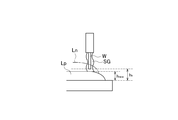
例えば、ロボットなどの自動機を用いたアーク溶接により溶融ビードを積層する場合、図4A及び図4Bに示すように、実際の溶融ビードの高さhnowが計画した溶融ビードの予定高さhkと異なる可能性がある。この場合、図4Aに示すように、前層のビードLpに対して次層のビードLnを溶接する際、シールドガスSGのシールド性が不安定となり、造形物の品質に影響を及ぼす場合がある。また、図4Bに示すように、実際の溶融ビードの高さhnowが計画した溶融ビードの予定高さhkより高いと、次層のビードLnを溶接する際、前層のビードLpがアーク溶接のトーチTや溶加材Wと干渉して、造形物の品質に悪影響を及ぼすと共に、自動機の停止や、トーチの損傷などの課題が生じる。
一方、特許文献1に記載の金型の製造方法では、積層高さの誤差補正や、各層の溶融ビードの高さ補正について考慮されておらず、改善の余地があった。
本発明は、前述した課題に鑑みてなされたものであり、その目的は、積層造形において、各層の溶融ビードの高さを適切に管理して、造形物の品質を向上すると共に、溶融ビードと積層装置との干渉を防止することができる積層造形物の製造方法、製造システム、及び製造プログラムを提供することにある。
本発明の上記目的は、下記の構成により達成される。
(1) 造形物の形状を表す形状データを取得する工程と、
前記形状データに基づいて前記造形物を互いに平行な複数の層に分割し、前記各層の形状を表す層形状データを生成する工程と、
前記各層の溶融ビードを形成し、前記造形物の形状が形成されるまで前記溶融ビードを積層する工程と、
を備え、
前記各層の溶融ビードの形成は、
前記各層の層形状データに基づいて積層装置によって溶融ビードを形成する工程と、
前記形成された溶融ビードの高さを計測する工程と、
前記計測された溶融ビードの高さが前記予定高さに対して許容差の範囲内であるか比較する工程と、
前記溶融ビードの高さが前記予定高さに対して前記許容差を引いた値より低い場合は、前記溶融ビードに重ねてさらに他の溶融ビードを形成する工程と、
前記溶融ビードの高さが前記予定高さに対して前記許容差を足した値より高い場合は、前記溶融ビードを削除する工程と、
を備える積層造形物の製造方法。
(2) 前記計測工程及び前記比較工程は、前記他の溶融ビード形成工程又は前記溶融ビード削除工程を実行した後に再度行う(1)に記載の積層造形物の製造方法。
(3) 造形物を互いに平行な複数の層に分割した、前記各層の形状を表す層形状データに基づいて、前記複数の層の溶融ビードを形成する積層装置と、
前記積層装置により形成された前記溶融ビードを切削可能な切削装置と、
前記形成された溶融ビードの高さを測定する高さ計測装置と、
前記各層の層形状データに基づいて前記複数の層の前記溶融ビードを形成するように前記積層装置を制御すると共に、前記各層の溶融ビードの形成ごとに、前記高さ計測装置によって計測された前記溶融ビードの高さが予定高さに許容差を引いた値より低い場合、前記溶融ビードに重ねてさらに他の溶融ビードを形成するように前記積層装置を制御し、前記溶融ビードの高さが前記予定高さに前記許容差を足した値より高い場合、前記溶融ビードを削除するように前記切削装置を制御する制御装置と、
を備える積層造形物の製造システム。
(4) 造形物の形状を表す形状データに基づいて前記造形物を複数の層に分割された、前記各層の形状を表す層形状データを用いて、前記各層の溶融ビードを形成し、前記造形物の形状が形成されるまで前記溶融ビードを積層する手順を実行する積層造形物の製造プログラムであって、
前記各層の溶融ビードの形成は、前記各層の層形状データに基づいて積層装置によって溶融ビードを形成する手順、前記形成された溶融ビードの高さを計測する手順、前記計測された溶融ビードの高さが前記予定高さに対して許容差の範囲内であるか比較する手順、前記溶融ビードの高さが予定高さに対して前記許容値を引いた値より低い場合は、前記溶融ビードに重ねてさらに他の溶融ビードを形成する手順、前記溶融ビードの高さが前記予定高さに対して前記許容値を足した値より高い場合は、前記溶融ビードを削除する手順、を実行する積層造形物の製造プログラム。
(1) 造形物の形状を表す形状データを取得する工程と、
前記形状データに基づいて前記造形物を互いに平行な複数の層に分割し、前記各層の形状を表す層形状データを生成する工程と、
前記各層の溶融ビードを形成し、前記造形物の形状が形成されるまで前記溶融ビードを積層する工程と、
を備え、
前記各層の溶融ビードの形成は、
前記各層の層形状データに基づいて積層装置によって溶融ビードを形成する工程と、
前記形成された溶融ビードの高さを計測する工程と、
前記計測された溶融ビードの高さが前記予定高さに対して許容差の範囲内であるか比較する工程と、
前記溶融ビードの高さが前記予定高さに対して前記許容差を引いた値より低い場合は、前記溶融ビードに重ねてさらに他の溶融ビードを形成する工程と、
前記溶融ビードの高さが前記予定高さに対して前記許容差を足した値より高い場合は、前記溶融ビードを削除する工程と、
を備える積層造形物の製造方法。
(2) 前記計測工程及び前記比較工程は、前記他の溶融ビード形成工程又は前記溶融ビード削除工程を実行した後に再度行う(1)に記載の積層造形物の製造方法。
(3) 造形物を互いに平行な複数の層に分割した、前記各層の形状を表す層形状データに基づいて、前記複数の層の溶融ビードを形成する積層装置と、
前記積層装置により形成された前記溶融ビードを切削可能な切削装置と、
前記形成された溶融ビードの高さを測定する高さ計測装置と、
前記各層の層形状データに基づいて前記複数の層の前記溶融ビードを形成するように前記積層装置を制御すると共に、前記各層の溶融ビードの形成ごとに、前記高さ計測装置によって計測された前記溶融ビードの高さが予定高さに許容差を引いた値より低い場合、前記溶融ビードに重ねてさらに他の溶融ビードを形成するように前記積層装置を制御し、前記溶融ビードの高さが前記予定高さに前記許容差を足した値より高い場合、前記溶融ビードを削除するように前記切削装置を制御する制御装置と、
を備える積層造形物の製造システム。
(4) 造形物の形状を表す形状データに基づいて前記造形物を複数の層に分割された、前記各層の形状を表す層形状データを用いて、前記各層の溶融ビードを形成し、前記造形物の形状が形成されるまで前記溶融ビードを積層する手順を実行する積層造形物の製造プログラムであって、
前記各層の溶融ビードの形成は、前記各層の層形状データに基づいて積層装置によって溶融ビードを形成する手順、前記形成された溶融ビードの高さを計測する手順、前記計測された溶融ビードの高さが前記予定高さに対して許容差の範囲内であるか比較する手順、前記溶融ビードの高さが予定高さに対して前記許容値を引いた値より低い場合は、前記溶融ビードに重ねてさらに他の溶融ビードを形成する手順、前記溶融ビードの高さが前記予定高さに対して前記許容値を足した値より高い場合は、前記溶融ビードを削除する手順、を実行する積層造形物の製造プログラム。
本発明の積層造形物の製造方法、製造システム、及び製造プログラムによれば、積層造形時に各層での溶融ビードの高さを計画通りの高さとすることが可能となり、結果として予め計画した溶融金属積層位置との誤差を抑制して造形精度が担保できる。また、造形中も溶接トーチと積層金属間の距離が適切になるため、シールドガスによるシールド性を確保でき、品質担保につながるだけでなく、溶接トーチなどの積層装置への衝突による破損を防止できる。
以下、本発明に係る積層造形物の製造方法及び製造システムの一実施形態を図面に基づいて詳細に説明する。なお、以下の実施形態は、本発明を具体化した一例であって、本発明の技術範囲を限定するものではない。
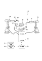
図1に示すように、本実施形態の積層造形物の製造システム10は、溶接ロボット20と、切削ロボット30と、高さ計測装置40と、制御装置50と、CAD/CAM装置51と、軌道計画手段52と、メモリー53と、を備える。即ち、本実施形態では、本発明の積層装置として、既存の溶接ロボット20が用いられ、本発明の切削装置として、既存の切削ロボット30が用いられている。
積層造形物の製造システム10は、溶接ロボット20により溶加材(ワイヤ)Wを溶融しながら、積層造形物11の各層L1・・・Lkの形状を表す層形状データに基づいて溶接トーチ22を移動させて、溶融ビード61を複数層L1・・・Lkに亘って積層することで積層造形物11を成形する。
なお、図1では、積層造形物11の一例として、溶融ビード61を螺旋状に連続して積層する(即ち、前層の溶融ビード61の終端部と次層の溶融ビード61の始端部とが連続する)ことで略円筒形状を成型する場合を示しているが、積層造形物11は、任意の形状に設定可能である。
なお、図1では、積層造形物11の一例として、溶融ビード61を螺旋状に連続して積層する(即ち、前層の溶融ビード61の終端部と次層の溶融ビード61の始端部とが連続する)ことで略円筒形状を成型する場合を示しているが、積層造形物11は、任意の形状に設定可能である。
溶接ロボット20は、多関節ロボットであり、先端アーム21の先端部に溶接トーチ22を備える。先端アーム21は、3次元的に移動可能であり、先端アーム21の姿勢及び位置を制御装置50で制御することにより、溶接トーチ22は、任意の姿勢で、任意の位置に移動することができる。
溶接トーチ22は、シールドガスSG(図3参照)が供給される略筒状のシールドノズルと、シールドノズルの内部に配置された不図示のコンタクトチップと、コンタクトチップに保持されて溶融電流が給電される溶加材Wと、を備える。溶接トーチ22は、溶加材Wを送給しつつ、シールドガスSGを流しながらアークを発生させて溶加材Wを溶融及び固化し、基台60上に溶融ビード61を積層して積層造形物11を形成する。なお、溶接トーチ22は、外部から溶加材を供給する非溶極式であってもよい。
切削ロボット30は、溶接ロボット20と同様に、多関節ロボットであり、先端アーム31の先端部に、例えば、エンドミルや研削砥石などの金属加工工具32を備える。これにより、切削ロボット30は、制御装置50により、その加工姿勢が任意の姿勢を取り得るように、3次元的に移動可能となっている。
切削ロボット30は、必要に応じて、溶接ロボット20により形成された溶融ビード61を金属加工工具32で所望に高さに加工する。
高さ計測装置40は、溶融ビード61の高さhnowを測定する装置であり、接触式、非接触式などの任意の高さ計測装置が使用可能であるが、形成直後の溶融ビード61は高温であるため、レーザ式、撮像式などの非接触式計測装置を用いるのが好ましい。高さ計測装置40は、1層の溶融ビード61が形成されるごとに該溶融ビード61の高さhnowを測定する。
CAD/CAM装置51は、形成する積層造形物11の形状データを作成した後、複数の層に分割して各層L1・・・Lkの形状を表す層形状データを生成する。軌道計画手段52は、層形状データに基づいて溶接トーチ22の移動軌跡を生成する。メモリー53は、生成された層形状データや溶接トーチ22の移動軌跡などを記憶する。
制御装置50は、内部に格納された製造プログラムを実行することで、メモリー53に記憶された層形状データや溶接トーチ22の移動軌跡に基づいて、溶接ロボット20を制御すると共に、後述するように、各層の溶融ビード61の状態に応じて、溶接ロボット20及び切削ロボット30の動きを制御する。
次に、図2及び図3を参照して、本実施形態の積層造形物の製造システム10により積層造形物11を成形する具体的な手順について詳述する。
図2のフローチャートに示すように、まず、CAD/CAM装置51により積層造形物11の形状を表す形状データを作成し、入力された形状データ(CADデータ)を複数の層L1…Lkに分割して、各層L1…Lkの形状を表す層形状データを生成する(ステップS1)。各層L1…Lkの形状を表す層形状データは、溶接トーチ22の移動軌跡、即ち、溶融ビード61の積層軌跡となる。
積層造形物11の形状データの複数層への分割は、溶融ビード61の積層方向に対して略直交方向に分割するのが好ましい。即ち、溶融ビード61を垂直方向に積層して積層造形物11を形成する場合には水平方向に分割し、溶融ビード61を水平方向に積層して積層造形物11を形成する場合は、垂直方向に分割する。以下では、溶融ビード61を垂直方向に積層して積層造形物11を形成する場合について説明する。
次いで、軌道計画手段52が、層形状データに基づいて、各層L1…Lkにおける溶接トーチ22の移動軌跡や、各層L1…Lkの溶融ビード61が積層された溶融ビード61の計画高さhk、などの具体的な溶融ビード61の積層計画を作成する(ステップS2)。
そして、制御装置50が備えるカウンタの数値をk=1にセットするとともに(ステップS3)、1層目の溶融ビード61が積層(形成)されたときの溶融ビード61の計画高さhkをh1にセットする(ステップS4)。ここで、計画高さhkは、積層された溶融ビード61の総高さ(合計高さ)とする。なお、各層L1…Lkごとの溶融ビード61の計画高さは、同じであってもよく、また各層L1…Lkの層形状データに従って層ごとに異なる高さであってもよい。
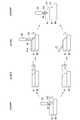
そして、図3に示すように、溶接トーチ22を、計画された移動軌跡に沿って移動させて、1層目の溶融ビード61を基台60上に積層する(ステップS5)。そして、高さ計測装置40により、1層目の溶融ビード61の高さhnowを測定する。なお、溶融ビード61の高さhnowの測定は、各層L1…Lkの溶融ビード61が形成されるごとに行う。
次いで、測定された溶融ビード61の高さhnowが、計画高さhkに対して許容差εの範囲内であるか否かを比較する。具体的には、測定された溶融ビード61の高さhnowが、計画高さhkから許容差εを引いた値と等しいか、又は大きいか否かが判別される(ステップS6)。
ステップS6において、溶融ビード61の高さhnowが、計画高さhkから許容差εを引いた値より小さいと判断されると、ステップS5に戻り、1層目の溶融ビード61の上にさらに追加の溶融ビード61aを積層し、再び溶融ビード61の高さhnowを測定して計画高さhkとの比較を行う。
これにより、溶融ビード61の高さhnowが、計画高さhkに近づけられる。この結果、溶融ビード61の高さhnowが計画高さhkより小さいまま、次層の溶融ビード61が積層されることによる、積層造形物11の品質への悪影響を抑制できる。
そして、溶融ビード61の高さhnowが、計画高さhkから許容差εを引いた値と等しいか、または大きいと判断されると、次のステップに進み、溶融ビード61の高さhnowが、計画高さhkに許容差εを足した値と等しいか、又は小さいか否かが判別される(ステップS7)。
溶融ビード61の高さhnowが、計画高さhkに許容差εを足した値より大きい場合は、切削ロボット30の金属加工工具32により、溶融ビード61の高さhnowが、計画高さhkになるように切削加工する(ステップS8)。
切削ロボット30により溶融ビード61を切削加工した後、ステップS6に戻り、再び、高さ計測装置40により切削加工後の溶融ビード61の高さhnowを測定して、計画高さhkと比較する。なお、溶融ビード61の切削加工により、溶融ビード61の高さhnowが計画高さhkに対して許容差εの範囲内であることが確実である場合には、図2に破線で示すように、計画した層数の溶融ビード61が積層されたか否かを判別するステップS9に進めてもよい。
ステップS7において、溶融ビード61の高さhnowが、計画高さhkに許容差εを足した値より大きいと、次層(2層目)の溶融ビード61を積層するときに、溶接トーチ22や溶加材Wが積層済みの1層目の溶融ビード61に当接して、溶接ロボット20の停止や溶接トーチ22の損傷などに繋がる虞があるが、溶融ビード61の高さhnowを、計画高さhkまで切削加工することでこれを防止することができる。
ステップS7で、溶融ビード61の高さhnowが、計画高さhkに許容差εを足した値と等しいか、又は小さい場合には、溶融ビード61の高さhnowは、許容差εの範囲内であると判断され、続いて計画した層数の溶融ビード61が積層されたか否かが判別される(ステップS9)。
ステップS9で計画した層数の溶融ビード61の積層が完了していないと判断されると、カウンタの数値をインクリメントしてk=2にセットして(ステップS10)、ステップS4に戻り、計画高さhkを、1層目と2層目の溶融ビード61の合計高さである新しい計画高さhkに変更して、次層(2層目)の溶融ビード61を1層目の溶融ビード61の上に積層する。
以後、同様に、計画した層数の溶融ビード61の積層が完了するまで、溶融ビード61の積層を繰り返し行って、積層造形物11を形成する。
ステップS9で計画した層数の溶融ビード61の積層が完了したと判断されると、積層造形物11の作成プログラムを終了する。
以上説明したように、本実施形態の積層造形物の製造方法、製造システムによれば、積層造形物11の形状を表す形状データを取得し、該形状データに基づいて積層造形物11を複数の層L1…Lkに分割した、各層L1…Lkの形状を表す層形状データを生成する。そして、溶接ロボット20は、各層L1…Lkの溶融ビード61を積層形成して、積層造形物11を形成する。各層L1…Lkの溶融ビード61の形成は、各層L1…Lkの層形状データに基づいて溶接ロボット20によって溶融ビード61を形成する工程と、形成された溶融ビード61の高さhnowを高さ計測装置40により計測する工程と、計測された溶融ビード61の高さhnowが、計画高さhkに対して許容差εの範囲内であるか比較し、溶融ビード61の高さhnowが、計画高さhkに対して許容差εを引いた値より低い場合は、溶接ロボット20が、溶融ビード61に重ねてさらに他の溶融ビード61aを形成する工程と、溶融ビード61の高さhnowが、計画高さhkに対して許容差εを足した値より高い場合は、溶融ビード61を切削ロボット30により削除する工程と、を備える。これにより、積層造形時に各層L1…Lkでの高さhnowを計画高さhkに対して許容差εの範囲内とすることが可能となり、結果として予め計画した溶融金属積層位置との誤差を抑制して高精度で積層造形物11を形成できる。
また、造形中も溶接トーチ22と溶融ビード61間の距離が適切になるため、シールドガスによるシールド性を確保でき、品質担保につながるだけでなく、溶接トーチ22や溶加材Wと溶融ビード61との衝突による停止や損傷を防止できる。
また、高さ計測装置40により計測された溶融ビード61の高さhnowと、計画高さhkとの比較は、追加の溶融ビード61aの積層、又は切削ロボット30による溶融ビード61の切削加工後に、再度行うので、より高い精度で積層造形物11を形成することができる。
また、本実施形態の積層造形物の製造プログラムによれば、溶接ロボット20が、各層L1…Lkの溶融ビード61を積層形成して、積層造形物11を形成する手順を実行する。また、各層L1…Lkの溶融ビード61の形成は、各層L1…Lkの層形状データに基づいて溶接ロボット20によって溶融ビード61を形成する手順と、形成された溶融ビード61の高さhnowを高さ計測装置40により計測する手順と、計測された溶融ビード61の高さhnowが、計画高さhkに対して許容差εの範囲内であるか比較し、溶融ビード61の高さhnowが、計画高さhkに対して許容差εを引いた値より低い場合は、溶接ロボット20が、溶融ビード61に重ねてさらに他の溶融ビード61aを形成する手順と、溶融ビード61の高さhnowが、計画高さhkに対して許容差εを足した値より高い場合は、溶融ビード61を切削ロボット30により削除する手順と、を実行する。これにより、積層造形時に各層L1…Lkでの高さhnowを計画高さhkに対して許容差εの範囲内とすることが可能となり、結果として予め計画した溶融金属積層位置との誤差を抑制して高精度で積層造形物11を形成できる。
なお、ステップS6において、他の溶融ビード61aを積層する際には、異なる溶加材Wや異なる溶接トーチ、また、異なる溶接条件で、積層誤差に応じて適切な高さの他の溶融ビード61aを積層するように行われてもよい。或いは、ステップS8での切削加工を予め見越して、溶融ビード61と同じ条件で、他の溶融ビード61aを積層してもよい。
なお、本発明は、前述した実施形態に限定されるものではなく、適宜、変形、改良、等が可能である。
例えば、上記実施形態では、溶融積層方式としてアーク溶接を適用した例について説明したが、他の金属溶融積層方法による積層装置、例えばSelective Laser Melting(SLM)、Laser Metal Deposition(LMD)のようなレーザによる溶融積層方式や、電子ビーム溶接なども適用可能である。
例えば、上記実施形態では、溶融積層方式としてアーク溶接を適用した例について説明したが、他の金属溶融積層方法による積層装置、例えばSelective Laser Melting(SLM)、Laser Metal Deposition(LMD)のようなレーザによる溶融積層方式や、電子ビーム溶接なども適用可能である。
なお、本出願は、2017年3月13日出願の日本特許出願(特願2017-047553)に基づくものであり、その内容はここに参照として取り込まれる。
10 積層造形物の製造システム
11 積層造形物
20 溶接ロボット(積層装置)
30 切削ロボット(切削装置)
40 高さ計測装置
50 制御装置
61 溶融ビード
61a 他の溶融ビード
L1・・・Lk 層
ε 許容差
hnow 溶融ビードの高さ
hk 溶融ビードの計画高さ(予定高さ)
11 積層造形物
20 溶接ロボット(積層装置)
30 切削ロボット(切削装置)
40 高さ計測装置
50 制御装置
61 溶融ビード
61a 他の溶融ビード
L1・・・Lk 層
ε 許容差
hnow 溶融ビードの高さ
hk 溶融ビードの計画高さ(予定高さ)
Claims (4)
- 造形物の形状を表す形状データを取得する工程と、
前記形状データに基づいて前記造形物を互いに平行な複数の層に分割し、前記各層の形状を表す層形状データを生成する工程と、
前記各層の溶融ビードを形成し、前記造形物の形状が形成されるまで前記溶融ビードを積層する工程と、
を備え、
前記各層の溶融ビードの形成は、
前記各層の層形状データに基づいて積層装置によって溶融ビードを形成する工程と、
前記形成された溶融ビードの高さを計測する工程と、
前記計測された溶融ビードの高さが前記予定高さに対して許容差の範囲内であるか比較する工程と、
前記溶融ビードの高さが前記予定高さに対して前記許容差を引いた値より低い場合は、前記溶融ビードに重ねてさらに他の溶融ビードを形成する工程と、
前記溶融ビードの高さが前記予定高さに対して前記許容差を足した値より高い場合は、前記溶融ビードを削除する工程と、
を備える積層造形物の製造方法。 - 前記計測工程及び前記比較工程は、前記他の溶融ビード形成工程又は前記溶融ビード削除工程を実行した後に再度行う請求項1に記載の積層造形物の製造方法。
- 造形物を互いに平行な複数の層に分割した、前記各層の形状を表す層形状データに基づいて、前記複数の層の溶融ビードを形成する積層装置と、
前記積層装置により形成された前記溶融ビードを切削可能な切削装置と、
前記形成された溶融ビードの高さを測定する高さ計測装置と、
前記各層の層形状データに基づいて前記複数の層の前記溶融ビードを形成するように前記積層装置を制御すると共に、前記各層の溶融ビードの形成ごとに、前記高さ計測装置によって計測された前記溶融ビードの高さが予定高さに許容差を引いた値より低い場合、前記溶融ビードに重ねてさらに他の溶融ビードを形成するように前記積層装置を制御し、前記溶融ビードの高さが前記予定高さに前記許容差を足した値より高い場合、前記溶融ビードを削除するように前記切削装置を制御する制御装置と、
を備える積層造形物の製造システム。 - 造形物の形状を表す形状データに基づいて前記造形物を複数の層に分割された、前記各層の形状を表す層形状データを用いて、前記各層の溶融ビードを形成し、前記造形物の形状が形成されるまで前記溶融ビードを積層する手順を実行する積層造形物の製造プログラムであって、
前記各層の溶融ビードの形成は、前記各層の層形状データに基づいて積層装置によって溶融ビードを形成する手順、前記形成された溶融ビードの高さを計測する手順、前記計測された溶融ビードの高さが前記予定高さに対して許容差の範囲内であるか比較する手順、前記溶融ビードの高さが予定高さに対して前記許容値を引いた値より低い場合は、前記溶融ビードに重ねてさらに他の溶融ビードを形成する手順、前記溶融ビードの高さが前記予定高さに対して前記許容値を足した値より高い場合は、前記溶融ビードを削除する手順、を実行する積層造形物の製造プログラム。
Priority Applications (3)
| Application Number | Priority Date | Filing Date | Title |
|---|---|---|---|
| US16/489,633 US20190381595A1 (en) | 2017-03-13 | 2018-03-13 | Manufacturing method, manufacturing system, and manufacturing program for additive manufactured object |
| CN201880018298.5A CN110430959B (zh) | 2017-03-13 | 2018-03-13 | 层叠造型物的制造方法、制造系统及存储介质 |
| EP18768083.0A EP3597342B1 (en) | 2017-03-13 | 2018-03-13 | Manufacturing method, manufacturing system, and manufacturing program for additive manufactured object |
Applications Claiming Priority (2)
| Application Number | Priority Date | Filing Date | Title |
|---|---|---|---|
| JP2017-047553 | 2017-03-13 | ||
| JP2017047553A JP6751040B2 (ja) | 2017-03-13 | 2017-03-13 | 積層造形物の製造方法、製造システム、及び製造プログラム |
Publications (1)
| Publication Number | Publication Date |
|---|---|
| WO2018168881A1 true WO2018168881A1 (ja) | 2018-09-20 |
Family
ID=63523902
Family Applications (1)
| Application Number | Title | Priority Date | Filing Date |
|---|---|---|---|
| PCT/JP2018/009819 Ceased WO2018168881A1 (ja) | 2017-03-13 | 2018-03-13 | 積層造形物の製造方法、製造システム、及び製造プログラム |
Country Status (5)
| Country | Link |
|---|---|
| US (1) | US20190381595A1 (ja) |
| EP (1) | EP3597342B1 (ja) |
| JP (1) | JP6751040B2 (ja) |
| CN (1) | CN110430959B (ja) |
| WO (1) | WO2018168881A1 (ja) |
Families Citing this family (27)
| Publication number | Priority date | Publication date | Assignee | Title |
|---|---|---|---|---|
| JP7010799B2 (ja) * | 2018-10-16 | 2022-01-26 | 株式会社神戸製鋼所 | 構造体の製造方法、及び構造体 |
| WO2020090074A1 (ja) * | 2018-10-31 | 2020-05-07 | 株式会社ニコン | 加工システム、及び、加工方法 |
| JP7223644B2 (ja) * | 2019-06-20 | 2023-02-16 | 株式会社神戸製鋼所 | 造形物の製造方法及び造形物の製造制御方法 |
| CA3145642A1 (en) * | 2019-07-03 | 2021-01-07 | Norsk Titanium As | Standoff distance monitoring and control for directed energy deposition additive manufacturing systems |
| CN114222642A (zh) * | 2019-08-07 | 2022-03-22 | 三菱电机株式会社 | 层叠造形装置、层叠造形方法及层叠造形程序 |
| CN114450122B (zh) * | 2019-10-03 | 2023-10-24 | 三菱电机株式会社 | 加工程序生成装置及方法、层叠造形装置及方法 |
| JP7388212B2 (ja) * | 2020-01-31 | 2023-11-29 | セイコーエプソン株式会社 | 三次元造形物の製造方法および三次元造形装置 |
| JP7391709B2 (ja) * | 2020-02-17 | 2023-12-05 | 株式会社神戸製鋼所 | 造形物の製造方法、造形物の製造装置、及びプログラム |
| DE112020006920T5 (de) | 2020-03-19 | 2022-12-29 | Mitsubishi Electric Corporation | Einrichtung zur erzeugung von pfaden für additive fertigung, verfahren zur erzeugung von pfaden für additive fertigung und einrichtung für maschinelles lernen |
| FR3110484B1 (fr) * | 2020-05-20 | 2022-06-03 | Arianegroup Sas | Procédé d’assemblage d’une première partie métallique avec une deuxième partie en matériau composite à matrice organique, et pièce résultant d’un tel assemblage |
| JP7384760B2 (ja) * | 2020-07-15 | 2023-11-21 | 株式会社神戸製鋼所 | 機械学習装置、積層造形システム、溶接条件の機械学習方法、溶接条件の調整方法、およびプログラム |
| JP7303162B2 (ja) * | 2020-07-15 | 2023-07-04 | 株式会社神戸製鋼所 | 積層造形物の製造方法 |
| JP7339215B2 (ja) * | 2020-07-20 | 2023-09-05 | 株式会社神戸製鋼所 | 積層造形物の製造システム、積層造形物の製造方法、及び積層造形物の製造プログラム |
| JP6892542B1 (ja) * | 2020-08-19 | 2021-06-23 | 株式会社神戸製鋼所 | 造形物の製造方法及び造形物 |
| JP6912636B1 (ja) * | 2020-08-19 | 2021-08-04 | 株式会社神戸製鋼所 | 積層造形物の製造システム、積層造形物の製造方法、及び積層造形物の製造プログラム |
| JP7428621B2 (ja) * | 2020-09-25 | 2024-02-06 | 株式会社神戸製鋼所 | 造形条件の設定方法、積層造形方法、積層造形システム、およびプログラム |
| JP7376455B2 (ja) * | 2020-10-28 | 2023-11-08 | 株式会社神戸製鋼所 | 積層計画作成方法 |
| JP7553400B2 (ja) * | 2021-04-16 | 2024-09-18 | 株式会社神戸製鋼所 | 積層造形方法、積層造形装置、及び積層造形物を造形するプログラム |
| JP7469264B2 (ja) * | 2021-07-28 | 2024-04-16 | 株式会社神戸製鋼所 | 造形装置の制御方法、造形装置及びプログラム |
| KR102513393B1 (ko) * | 2021-08-31 | 2023-03-23 | 한국생산기술연구원 | 와이어 아크 3d 적층법으로 제조한 nab 합금 프로펠러의 제조방법 |
| KR102591784B1 (ko) * | 2021-10-29 | 2023-10-23 | 한국생산기술연구원 | 건축물 적층 제조용 3d 프린팅 방식 건축재료 공급장치를 이용한 사전 모의적층 소재물성 진단방법 |
| JP7609823B2 (ja) * | 2022-05-16 | 2025-01-07 | 株式会社神戸製鋼所 | 溶接ビード形状の制御方法、電源制御方法、積層造形方法、制御装置、電源装置、溶接システム、積層造形システム及びプログラム |
| JP7697918B2 (ja) * | 2022-11-16 | 2025-06-24 | 株式会社神戸製鋼所 | ロボットの制御装置、制御方法、およびプログラム |
| EP4400243A1 (en) * | 2023-01-11 | 2024-07-17 | Fundación AITIIP | Method of additive manufacturing for manufacturing molds an additive manufacturing system for manufacturing molds |
| JP7374390B1 (ja) * | 2023-02-08 | 2023-11-06 | 三菱電機株式会社 | 欠陥推定装置、数値制御装置、付加製造装置、および欠陥推定方法 |
| WO2025253440A1 (ja) * | 2024-06-03 | 2025-12-11 | 三菱電機株式会社 | 積層造形装置および積層造形方法 |
| US12572131B1 (en) * | 2025-06-27 | 2026-03-10 | Ut-Battelle, Llc | Flexibilities used in slicer to ensure level printing for additive system |
Citations (5)
| Publication number | Priority date | Publication date | Assignee | Title |
|---|---|---|---|---|
| JPH05192767A (ja) * | 1991-07-29 | 1993-08-03 | Fritz B Prinz | 付着溶接によって3次元的金属物品を作製するための方法及び装置 |
| JP2004230431A (ja) * | 2003-01-31 | 2004-08-19 | Fujitsu Ltd | 物体加工のための情報処理方法及びプログラム |
| JP3784539B2 (ja) | 1998-07-01 | 2006-06-14 | 本田技研工業株式会社 | 金型の製造方法 |
| JP3208808U (ja) * | 2013-10-22 | 2017-02-23 | リンカーン グローバル,インコーポレイテッド | 付加製造のために位置フィードバックを提供するシステム |
| JP2017047553A (ja) | 2015-08-31 | 2017-03-09 | 住友金属鉱山株式会社 | 円筒形成形型、並びに、円筒形セラミックス成形体およびその製造方法 |
Family Cites Families (15)
| Publication number | Priority date | Publication date | Assignee | Title |
|---|---|---|---|---|
| DE10344901B4 (de) * | 2002-09-30 | 2006-09-07 | Matsushita Electric Works, Ltd., Kadoma | Verfahren zum Herstellen eines dreidimensionalen gesinterten Produkts |
| US7358457B2 (en) * | 2006-02-22 | 2008-04-15 | General Electric Company | Nozzle for laser net shape manufacturing |
| JP5190023B2 (ja) * | 2009-05-20 | 2013-04-24 | 株式会社神戸製鋼所 | 溶接設定装置、溶接ロボットシステムおよび溶接設定プログラム |
| FR2983424B1 (fr) * | 2011-12-02 | 2014-09-19 | Nantes Ecole Centrale | Procede et dispositif d'usinage par addition de matiere et mise en forme combinees |
| CN103374721B (zh) * | 2012-04-27 | 2015-06-03 | 沈阳新松机器人自动化股份有限公司 | 用于轧辊激光熔覆的实时在线数据采集及远程监控系统 |
| WO2015058182A1 (en) * | 2013-10-18 | 2015-04-23 | +Mfg, LLC | Method and apparatus for fabrication of articles by molten and semi-molten deposition |
| JP5878604B1 (ja) * | 2014-10-21 | 2016-03-08 | アドバンスト・リサーチ・フォー・マニュファクチャリング・システムズ・リミテッド・ライアビリティ・カンパニーAdvanced Research For Manufacturing Systems, Llc | 複合材の製造方法 |
| TWI611909B (zh) * | 2014-11-29 | 2018-01-21 | National Tsing Hua University | 彈性變向佈料高速3d成形技術 |
| CN204524771U (zh) * | 2014-12-30 | 2015-08-05 | 深圳市圆梦精密技术研究院 | 激光熔融及激光铣削复合3d打印设备 |
| US10421267B2 (en) * | 2015-02-12 | 2019-09-24 | Arevo, Inc. | Method to monitor additive manufacturing process for detection and in-situ correction of defects |
| CN107428080A (zh) * | 2015-03-12 | 2017-12-01 | 株式会社尼康 | 三维造型物制造装置及构造物的制造方法 |
| US20170008114A1 (en) * | 2015-07-09 | 2017-01-12 | Lincoln Global, Inc. | System and method of controlling attachment and release of additive manufacturing builds using a welding process |
| CN105499904B (zh) * | 2016-01-04 | 2017-12-08 | 湘潭大学 | 一种基于增减材制造的零件修复装置及其使用方法 |
| CN106425490B (zh) * | 2016-09-05 | 2018-06-29 | 华中科技大学 | 一种增减材复合加工设备及其应用 |
| EP3338935A1 (en) * | 2016-12-22 | 2018-06-27 | MAN Truck & Bus AG | 3d printing apparatus |
-
2017
- 2017-03-13 JP JP2017047553A patent/JP6751040B2/ja active Active
-
2018
- 2018-03-13 EP EP18768083.0A patent/EP3597342B1/en active Active
- 2018-03-13 CN CN201880018298.5A patent/CN110430959B/zh active Active
- 2018-03-13 WO PCT/JP2018/009819 patent/WO2018168881A1/ja not_active Ceased
- 2018-03-13 US US16/489,633 patent/US20190381595A1/en not_active Abandoned
Patent Citations (5)
| Publication number | Priority date | Publication date | Assignee | Title |
|---|---|---|---|---|
| JPH05192767A (ja) * | 1991-07-29 | 1993-08-03 | Fritz B Prinz | 付着溶接によって3次元的金属物品を作製するための方法及び装置 |
| JP3784539B2 (ja) | 1998-07-01 | 2006-06-14 | 本田技研工業株式会社 | 金型の製造方法 |
| JP2004230431A (ja) * | 2003-01-31 | 2004-08-19 | Fujitsu Ltd | 物体加工のための情報処理方法及びプログラム |
| JP3208808U (ja) * | 2013-10-22 | 2017-02-23 | リンカーン グローバル,インコーポレイテッド | 付加製造のために位置フィードバックを提供するシステム |
| JP2017047553A (ja) | 2015-08-31 | 2017-03-09 | 住友金属鉱山株式会社 | 円筒形成形型、並びに、円筒形セラミックス成形体およびその製造方法 |
Non-Patent Citations (1)
| Title |
|---|
| See also references of EP3597342A4 |
Also Published As
| Publication number | Publication date |
|---|---|
| JP6751040B2 (ja) | 2020-09-02 |
| JP2018149570A (ja) | 2018-09-27 |
| CN110430959A (zh) | 2019-11-08 |
| US20190381595A1 (en) | 2019-12-19 |
| EP3597342A1 (en) | 2020-01-22 |
| CN110430959B (zh) | 2021-06-04 |
| EP3597342B1 (en) | 2022-08-17 |
| EP3597342A4 (en) | 2021-01-20 |
Similar Documents
| Publication | Publication Date | Title |
|---|---|---|
| JP6751040B2 (ja) | 積層造形物の製造方法、製造システム、及び製造プログラム | |
| WO2018180135A1 (ja) | 積層造形物の製造方法及び製造システム | |
| EP3711887B1 (en) | Method and apparatus for manufacturing layered model | |
| US11945031B2 (en) | Laminated molded object production method and production device | |
| EP3711888B1 (en) | Method and device for manufacturing shaped objects | |
| CN115956011B (zh) | 层叠造型物的制造系统、层叠造型物的制造方法以及存储介质 | |
| JP7160759B2 (ja) | 構造体の製造システム及び製造方法 | |
| CN115666838A (zh) | 层叠造形方法 | |
| US12005529B2 (en) | Method for manufacturing laminated molding, and laminated molding | |
| CN116096521B (zh) | 层叠造型物的制造方法 | |
| JP2019081187A (ja) | 積層造形物の製造方法 | |
| JP2018086664A (ja) | 溶接装置、溶接方法、三次元造形装置、及び三次元造形方法 | |
| CN115835930A (zh) | 层叠造形物的制造方法 | |
| CN116133802A (zh) | 层叠造型物的制造系统、层叠造型物的制造方法以及层叠造型物的制造程序 | |
| JP7688010B2 (ja) | 造形物の製造方法及び製造装置 | |
| WO2023149142A1 (ja) | 制御情報生成装置、制御情報生成方法、溶接制御装置及び制御情報生成プログラム |
Legal Events
| Date | Code | Title | Description |
|---|---|---|---|
| 121 | Ep: the epo has been informed by wipo that ep was designated in this application |
Ref document number: 18768083 Country of ref document: EP Kind code of ref document: A1 |
|
| NENP | Non-entry into the national phase |
Ref country code: DE |
|
| ENP | Entry into the national phase |
Ref document number: 2018768083 Country of ref document: EP Effective date: 20191014 |