WO2018174157A1 - Structure de fixation et dispositif à clavier - Google Patents
Structure de fixation et dispositif à clavier Download PDFInfo
- Publication number
- WO2018174157A1 WO2018174157A1 PCT/JP2018/011404 JP2018011404W WO2018174157A1 WO 2018174157 A1 WO2018174157 A1 WO 2018174157A1 JP 2018011404 W JP2018011404 W JP 2018011404W WO 2018174157 A1 WO2018174157 A1 WO 2018174157A1
- Authority
- WO
- WIPO (PCT)
- Prior art keywords
- screw
- wood
- fastened
- fastening structure
- component
- Prior art date
- Legal status (The legal status is an assumption and is not a legal conclusion. Google has not performed a legal analysis and makes no representation as to the accuracy of the status listed.)
- Ceased
Links
Images




Classifications
-
- F—MECHANICAL ENGINEERING; LIGHTING; HEATING; WEAPONS; BLASTING
- F16—ENGINEERING ELEMENTS AND UNITS; GENERAL MEASURES FOR PRODUCING AND MAINTAINING EFFECTIVE FUNCTIONING OF MACHINES OR INSTALLATIONS; THERMAL INSULATION IN GENERAL
- F16B—DEVICES FOR FASTENING OR SECURING CONSTRUCTIONAL ELEMENTS OR MACHINE PARTS TOGETHER, e.g. NAILS, BOLTS, CIRCLIPS, CLAMPS, CLIPS OR WEDGES; JOINTS OR JOINTING
- F16B5/00—Joining sheets or plates, e.g. panels, to one another or to strips or bars parallel to them
- F16B5/02—Joining sheets or plates, e.g. panels, to one another or to strips or bars parallel to them by means of fastening members using screw-thread
-
- F—MECHANICAL ENGINEERING; LIGHTING; HEATING; WEAPONS; BLASTING
- F16—ENGINEERING ELEMENTS AND UNITS; GENERAL MEASURES FOR PRODUCING AND MAINTAINING EFFECTIVE FUNCTIONING OF MACHINES OR INSTALLATIONS; THERMAL INSULATION IN GENERAL
- F16B—DEVICES FOR FASTENING OR SECURING CONSTRUCTIONAL ELEMENTS OR MACHINE PARTS TOGETHER, e.g. NAILS, BOLTS, CIRCLIPS, CLAMPS, CLIPS OR WEDGES; JOINTS OR JOINTING
- F16B25/00—Screws that cut thread in the body into which they are screwed, e.g. wood screws
- F16B25/0036—Screws that cut thread in the body into which they are screwed, e.g. wood screws characterised by geometric details of the screw
-
- G—PHYSICS
- G10—MUSICAL INSTRUMENTS; ACOUSTICS
- G10C—PIANOS, HARPSICHORDS, SPINETS OR SIMILAR STRINGED MUSICAL INSTRUMENTS WITH ONE OR MORE KEYBOARDS
- G10C3/00—Details or accessories
- G10C3/12—Keyboards; Keys
-
- G—PHYSICS
- G10—MUSICAL INSTRUMENTS; ACOUSTICS
- G10C—PIANOS, HARPSICHORDS, SPINETS OR SIMILAR STRINGED MUSICAL INSTRUMENTS WITH ONE OR MORE KEYBOARDS
- G10C3/00—Details or accessories
- G10C3/12—Keyboards; Keys
- G10C3/125—Materials or treatment of materials for the manufacturing of keys
-
- G—PHYSICS
- G10—MUSICAL INSTRUMENTS; ACOUSTICS
- G10C—PIANOS, HARPSICHORDS, SPINETS OR SIMILAR STRINGED MUSICAL INSTRUMENTS WITH ONE OR MORE KEYBOARDS
- G10C3/00—Details or accessories
- G10C3/16—Actions
-
- G—PHYSICS
- G10—MUSICAL INSTRUMENTS; ACOUSTICS
- G10C—PIANOS, HARPSICHORDS, SPINETS OR SIMILAR STRINGED MUSICAL INSTRUMENTS WITH ONE OR MORE KEYBOARDS
- G10C9/00—Methods, tools or materials specially adapted for the manufacture or maintenance of musical instruments covered by this subclass
-
- F—MECHANICAL ENGINEERING; LIGHTING; HEATING; WEAPONS; BLASTING
- F16—ENGINEERING ELEMENTS AND UNITS; GENERAL MEASURES FOR PRODUCING AND MAINTAINING EFFECTIVE FUNCTIONING OF MACHINES OR INSTALLATIONS; THERMAL INSULATION IN GENERAL
- F16B—DEVICES FOR FASTENING OR SECURING CONSTRUCTIONAL ELEMENTS OR MACHINE PARTS TOGETHER, e.g. NAILS, BOLTS, CIRCLIPS, CLAMPS, CLIPS OR WEDGES; JOINTS OR JOINTING
- F16B25/00—Screws that cut thread in the body into which they are screwed, e.g. wood screws
- F16B25/001—Screws that cut thread in the body into which they are screwed, e.g. wood screws characterised by the material of the body into which the screw is screwed
- F16B25/0015—Screws that cut thread in the body into which they are screwed, e.g. wood screws characterised by the material of the body into which the screw is screwed the material being a soft organic material, e.g. wood or plastic
-
- F—MECHANICAL ENGINEERING; LIGHTING; HEATING; WEAPONS; BLASTING
- F16—ENGINEERING ELEMENTS AND UNITS; GENERAL MEASURES FOR PRODUCING AND MAINTAINING EFFECTIVE FUNCTIONING OF MACHINES OR INSTALLATIONS; THERMAL INSULATION IN GENERAL
- F16B—DEVICES FOR FASTENING OR SECURING CONSTRUCTIONAL ELEMENTS OR MACHINE PARTS TOGETHER, e.g. NAILS, BOLTS, CIRCLIPS, CLAMPS, CLIPS OR WEDGES; JOINTS OR JOINTING
- F16B5/00—Joining sheets or plates, e.g. panels, to one another or to strips or bars parallel to them
Definitions
- the present invention relates to a fastening structure and a keyboard device.
- Patent Document 1 discloses a structure in which two wood parts are fixed using a nail having a screw function of biting into wood by rotating with a screwdriver in addition to the function of biting into wood by driving.
- the present invention has been made in view of the above-described circumstances, and a fastening structure and a keyboard capable of suppressing loosening of a fastening state between a fastened part and a wood part even when the wood part expands or contracts.
- An object is to provide an apparatus.
- the fastening structure is a fastening structure in which a part to be fastened is fastened to a wood part with a screw, the wood part is made of wood having a specific gravity of 0.85 g / cm 3 or less, and the screw has a nominal diameter of 3.5 mm.
- An intermediate position in the longitudinal direction of the effective screw portion which is a portion where the male screw portion formed on the shaft portion of the screw and the wood component mesh with each other, and a contact surface of the wood component with the fastened component Is 8 mm or less.
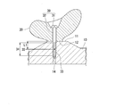
- FIG. 1 schematically shows an example of the fastening structure of the first embodiment.
- the fastening structure of the present embodiment includes a wood part 10, a fastening part 20, and a screw 30.
- the shaft portion 32 of the screw 30 is fastened to the wood part 10 through the fastened part 20, the fastened part 20 is fastened to the wood part 10.
- the length of the screw 30 is 30 mm or less.
- the thickness of the wood part 10 is about 30 mm.
- the wood constituting the wood part 10 preferably has a specific gravity of 0.08 to 0.85 g / cm 3 .
- balsa material corresponds to the wood having a specific gravity of 0.08 g / cm 3 .
- an Indian rosewood material corresponds to the wood having a specific gravity of 0.85 g / cm 3 .
- Soft materials such as conifers have a small specific gravity, but it is easy to obtain long members suitable for musical instrument parts such as wooden keys.
- specific gravity of the wood part 10 include about 0.85 g / cm 3, about 0.7 g / cm 3, about 0.6 g / cm 3, about 0.5 g / cm 3, about 0.4 g / cm 3 , For example, about 0.3 g / cm 3 .
- the part to be fastened 20 is not particularly limited, but can be composed of resin, metal, base material, or the like.
- the screw 30 has a head portion 31 and a shaft portion 32.
- the head portion 31 is provided at one end of the shaft portion 32.
- a pan head, a saucer head, a round saucer head, a cheese head, a truss head, a bind head, a low head, etc. are illustrated.
- the head portion 31 is provided with a driving recess for turning the screw 30 with a tool such as a screwdriver. Examples of the driving recess include a slot (groove), a cross hole, a hexagonal hole, and a square hole.
- the head portion 31 has a seat surface as a portion that receives a direct force when the screw 30 is tightened at a boundary portion with the shaft portion 32.
- a seat surface as a portion that receives a direct force when the screw 30 is tightened at a boundary portion with the shaft portion 32.
- Examples of the shape of the seating surface include a flat surface and a conical surface. When the seating surface is non-planar, the entire seating surface is included in the head 31.
- a male screw portion 33 is formed on the shaft portion 32.
- the male screw portion 33 may be formed up to the vicinity of the seating surface of the head portion 31. Examples of the shape of the male screw portion 33 include a triangular screw, a square screw, a trapezoidal screw, and a bulb screw.
- the shaft portion 32 between the head portion 31 and the male screw portion 33 may be provided with a cylindrical portion that does not have a thread and a thread groove. Examples of the screws for fastening to the wood part 10 include wood screws and tapping screws.
- a screw having a nominal diameter D of 0.8 mm to 3.5 mm is used as the screw 30, a screw having a nominal diameter D of 0.8 mm to 3.5 mm is used. Examples of the nominal diameter of the screw 30 include about 1.6 mm, about 1.8 mm, about 2.1 mm, about 2.4 mm, about 2.7 mm, about 3.1 mm, and about 3.5 mm.
- a portion around the shaft portion 32 of the fastened component 20 is sandwiched between the surface 11 of the wood component 10 and the head portion 31 of the screw 30.
- the contact surface 12 is a portion of the surface 11 of the wood component 10 that contacts the fastened component 20 side.
- the shaft vicinity portion 13 is a range extending from the contact surface 12 in parallel with the axis A of the screw 30.
- the effective screw portion 34 is a portion where the male screw portion 33 and the wood part 10 are engaged with each other.
- a spacer may be interposed between the wood part 10 and the fastened part 20 for fine adjustment of height and angle. In this case, it can be said that two or more of the parts to be fastened 20 and the spacers are fastened parts fastened to the wood part 10.
- the distance L1 between the intermediate position 35 in the longitudinal direction of the effective screw portion 34 and the contact surface 12 of the wood part 10 with the fastened part 20 is 1 mm or more and 15 mm or less, and more preferably. Is 8 mm or less.
- the distance L1 is less than 1 mm, the practical strength of the screw 30 is not generated.
- 15 mm which is the upper limit of the distance L1 is about 1 ⁇ 2 of the thickness of the wood part 10, and it is considered that the fastening strength of the screw 30 does not change even if it is longer than 15 mm.
- the distance L1 between the effective screw portion 34 and the contact surface 12 is short.
- the amount of displacement of the fastened component 20 that comes into contact with is small.
- the fastened part 20 can be displaced in the direction in which the screw 30 is pulled out from the head 31 along the longitudinal direction of the screw 30.
- the displacement amount of the fastened component 20 is large, the force in the direction of pulling out the screw 30 acts more strongly.
- a plastic permanent deformation occurs in the meshing between the male screw portion 33 and the wood part 10, and the fastening structure may be deteriorated or damaged, and the fastening state may be loosened.
- the target range that can affect the displacement of the fastened part 20 during the expansion of the wood part 10 is estimated to be approximately the range of the distance from the contact surface 12 to the effective screw part 34.
- the average position of the meshing portion with the male screw portion 33 is an intermediate position 35 of the effective screw portion 34.
- the distance L ⁇ b> 1 between the intermediate position 35 and the contact surface 12 indicates the size of a target range in which the head 31 of the screw 30 is displaced via the component to be fastened 20 when the wood component 10 is expanded. That is, the magnitude of the distance L1 is reflected in the magnitude of the displacement amount of the fastened part 20 relative to the intermediate position 35 when the wood part 10 is expanded.
- a reference can be set by defining an upper limit for the distance L1 between the intermediate position 35 and the contact surface 12. That is, if the target range that affects the displacement of the fastened component 20 during the expansion of the wood part 10 is shortened, the amount by which the screw 30 is pulled out in the vicinity of the effective screw portion 34 is reduced. As a result, the amount by which the screw 30 is pulled out easily falls within the range in which the wood structure is reversibly deformed.
- the upper limit value of the distance L1 can be experimentally obtained for a fastening structure with respect to a soft material such as a conifer.
- the distance L1 is 8 mm or less, loosening of the state of the fastening structure is effectively prevented.
- Examples of the distance L1 include, but are not limited to, about 8 mm, about 7 mm, about 6 mm, about 5 mm, about 4 mm, about 3 mm, and the like.
- a pilot hole 14 is provided in the wood part 10 in order to facilitate fastening of the screw 30 to the wood part 10.
- the inner diameter of the lower hole 14 is usually made thinner than the shaft part 32 of the screw 30 so that the male screw part 33 can easily mesh with the inner surface of the lower hole 14.
- FIG. 2 schematically shows a modified example of the fastening structure of the first embodiment.
- illustration of the fastened component 20 is omitted.
- the screw 30 is engaged with the wood part 10 without providing a prepared hole in the wood part 10.
- a recess 15 is formed on the side opposite to the contact surface 12 of the wood part 10.
- the male screw portion 33 is not engaged with the wood part 10 in the recess 15. For this reason, the range where the male screw portion 33 is exposed in the recess 15 is excluded from the effective screw portion 34.
- FIG. 3 schematically shows an example of the fastening structure of the second embodiment.
- FIG. 3A is a transverse sectional view of the contact surface 12
- FIG. 3B is a longitudinal sectional view along the longitudinal direction of the screw 30.
- the area of the contact surface 12 is 100 mm 2 or less per screw.
- the specific gravity of the wood part 10 is 0.85 g / cm 3 or less
- the nominal diameter of the screw 30 is preferably 0.8 mm or more and 3.5 mm or less.
- the distance L1 between the intermediate position 35 of the effective screw portion 34 and the contact surface 12 of the wood part 10 is preferably 1 mm or more and 15 mm or less, more preferably 8 mm or less.
- the load of action / reaction concentrates on the contact surface 12 between the wood part 10 and the part 20 to be fastened. Therefore, in the present embodiment, by providing an upper limit on the area of the contact surface 12, the layer on the surface 11 side in the vicinity of the contact surface 12 of the wood part 10 can be reversibly compressed and deformed. Combined with the effect of reversibly deforming the wood structure that meshes with the effective screw portion 34, by combining the conditions for setting the upper limit on the distance L1 and the conditions for setting the upper limit on the area of the contact surface 12 per screw, The effect of preventing loosening of the screw 30 can be expanded.
- the upper limit value of the area of the contact surface 12 per screw can be experimentally obtained for a fastening structure for a soft material such as a conifer. If the area of the contact surface 12 per screw is 100 mm 2 or less, loosening of the state of the fastening structure is effectively prevented. Exemplary of the area of the abutment surface 12 per one screw, but are not limited to, 100 mm 2 approximately, 90 mm 2 approximately, 80 mm 2 approximately, 70 mm 2 approximately, 60 mm 2 approximately, 50 mm 2 approximately, 40 mm 2 approximately, 30 mm 2 or so.
- FIG. 4 schematically shows a modified example of the fastening structure of the second embodiment.
- a plurality of protrusions 22 are formed on the back surface 21 on the side where the fastened component 20 faces the wood component 10.
- the total area in which the plurality of protrusions 22 corresponding to one screw 30 abuts against the wood part 10 is the area of the abutment surface 12 per screw.
- the shape of the protrusion 22 is not particularly limited, and examples thereof include a mountain shape, a dot shape, a boss shape, and a rib shape.
- the tip surface of the protrusion 22 abuts against the component facing the protrusion 22.
- FIG. 5 schematically shows an example of the fastening structure of the third embodiment.
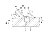
- the distance L2 between the pressed surface 23 of the fastened component 20 and the contact surface 12 of the wood component 10 with the fastened component 20 is 2 mm or less.
- the pressed surface 23 is a portion where the fastened component 20 is pressed from the head portion 31 of the screw 30.
- the specific gravity of the wood part 10 of the present embodiment is 0.85 g / cm 3 or less, and the nominal diameter of the screw 30 is preferably 0.8 mm to 3.5 mm.
- the nominal diameter of the screw 30 is preferably 0.8 mm to 3.5 mm.
- the distance L1 between the intermediate position 35 of the effective screw portion 34 and the contact surface 12 of the wood part 10 is preferably 1 mm or more and 15 mm or less, more preferably 8 mm or less.
- the area of the contact surface 12 may be 100 mm 2 or less per screw.
- the fastened component 20 When the fastened component 20 includes wood, the wood contained in the fastened component 20 expands due to moisture absorption and contracts due to drying. In addition, when the fastened component 20 is a non-wood material such as metal or resin, the expansion or contraction due to temperature is larger than that of wood, and it expands at a high temperature and contracts at a low temperature.
- the head portion 31 of the screw 30 When the fastened component 20 expands, the head portion 31 of the screw 30 can be displaced in the direction in which the screw 30 is pulled out of the head portion 31 along the longitudinal direction of the screw 30.
- the displacement amount of the head 31 When the displacement amount of the head 31 is large, the force in the direction of pulling out the screw 30 acts more strongly, and a plastic permanent deformation occurs in the meshing between the male screw portion 33 and the wood part 10, and the fastening structure is deteriorated. Damage may occur and the fastening state may be loosened.
- the distance L2 between the pressed surface 23 and the contact surface 12
- the absolute amount of expansion or contraction of the fastened component 20 is reduced, and the expansion or contraction of the fastened component 20 is achieved.
- the looseness of the screw 30 due to the above can be suppressed.
- the distance L2 include, but are not limited to, about 2 mm, about 1.5 mm, about 1 mm, and about 0.5 mm.
- the position of the pressed surface 23 is the position closest to the contact surface 12 among the locations where the head portion 31 contacts the fastening component 20. Good.
- a washer (not shown) is interposed between the head 31 of the screw 30 and the pressed surface 23 of the component 20 to be fastened, the thickness of the washer may be excluded from the distance L2.
- the fastened part 20 is made of wood having a specific gravity of 0.85 g / cm 3 or less, like the wood part 10, the total amount of the distance L 1 and the distance L 2, that is, the intermediate position of the effective screw portion 34.
- An upper limit may be provided for the distance between 35 and the pressed surface 23 of the component 20 to be fastened.
- the distance L3 is preferably 10 mm or less. Examples of the distance L3 include, but are not limited to, about 10 mm, about 9 mm, about 8 mm, about 7 mm, about 6 mm, about 5 mm, about 4 mm, about 3 mm, and the like.
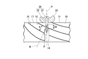
- FIG. 6 schematically shows an example of the fastening structure of the fourth embodiment.
- the effective screw portion 34 may be entangled with the winter eye 16 of the wood part 10.
- Wood that grows from the temperate zone to the cold zone usually has winter rings 16 and summer eyes 17 that are alternately formed due to the difference in the growth rate of the cell wall depending on the season. Winter eyes 16 have a higher strength than summer eyes 17, and variations due to characteristic differences between winter eyes 16 and summer eyes 17 are greater. For this reason, when the external thread part 33 meshes with the part containing the winter eyes 16, a viscoelastic reversible deformation characteristic can be improved.
- the value (R / cos ⁇ ) obtained by dividing the average annual ring interval R by the cosine of the angle ⁇ formed by the axis A of the screw 30 and the normal line N of the annual ring surface is along the axis A.
- ⁇ Fastening with screws 30 has fewer management items and better workability than adhesion. Further, since the screw 30 is detachable, when a spacer is interposed between the wood part 10 and the fastened part 20, it is possible to adjust the height and angle while trying. When the component to be fastened is fixed by bonding or the like, it is difficult to attach or detach it even if the height or angle of the component to be fastened is finely adjusted thereafter. For this reason, when fixing a functional part to wood parts, such as a wooden key in a keyboard musical instrument, for example, a functional part can be fastened to a wood part with a screw, and stability of quality and workability improvement can be aimed at. By making the functional part detachable from the wood part, it is possible to replace the functional part with a spacer having a different height or angle.
- Functional parts for musical instruments include operating force transmission members (switch drive (SW) actuators, hammer drive actuators, after-sensor pushers, etc.), motion detection means (sensors, reflectors, gray scales, shutter plates, etc.), key guides Examples thereof include a mechanism, a key operation restriction mechanism (rest, postcard, L foot, etc.), a cushioning material (felt, rubber, foam material, etc.), a mass body (counterweight, etc.), a protective plate (grease cover, etc.), and the like.
- the musical instrument is not particularly limited, and examples thereof include a keyboard instrument such as a piano, a stringed instrument such as a harp, a percussion instrument, and a wind instrument.
- FIG. 7 schematically shows a main part of a keyboard device in a keyboard instrument.
- FIG. 7 shows one white key 41W and one black key 41B of the keyboard device 40.
- the wooden key 41 is a long part. For this reason, it is advantageous to construct the wooden key 41 from a conifer that has a high degree of straightness in the wood and is easy to obtain a member that does not have an excluded portion such as a node over a certain distance.
- a back check component 42 is fixed near one end of the wooden key 41.
- the back check component is a mechanism component that receives a hammer included in an action mechanism (not shown) of a keyboard instrument. When the wooden key 41 is pressed, the hammer strikes the string in conjunction with the movement, and then rebounds and returns. The back check component receives the returned hammer and brakes it.
- the fastening structure of each of the above-described embodiments can be adopted as the fastening structure using the screw 30.
- a back check part 42 or a spacer can be cited as a part to be fastened to the wooden key 41.
- the position of the contact surface 12 of the wood component 10 shown in FIG. 1 with the fastened component 20 is the surface on which the wooden key contacts the spacer. It may be the position.
- a counter weight may be fixed to a wooden key of a keyboard device as a mass body for balancing with an action part such as a hammer.
- an action part such as a hammer.
- the present invention is not limited to this.
- the above-described fastening structure is suitable for applications in which other parts are fastened to, for example, a long wood part and a fastening state that is difficult to loosen is required. Examples of other applications include crafts and karakuri.
- the screw used in the above-described embodiment is not limited to a general single thread, and a double thread may be used. In the single screw, the distance (lead) traveled by one rotation is equal to the pitch, and moves one pitch by one rotation.
- a double thread is a thread in which there are two spirals in one pitch and the lead is twice that of a single thread.
- Thread axis D Thread nominal diameter L1 Distance between the intermediate position of the effective thread and the contact surface L2 Distance between the pressed surface and the contact surface N Normal to the annual ring surface R Average annual ring interval ⁇ Thread axis and annual ring Angle 10 with normal of the surface Wood part 11 Surface 12 Contact surface 13 Axis vicinity part 14 Lower hole 15 Recess 16 Winter eye 17 Natsume 20 Fastened part 21 Back face 22 Projection 23 Pressed face 30 Screw 31 Head 32 Axis Part 33 Male thread part 34 Effective thread part 35 Intermediate position 40 Keyboard device 41 Wooden key 42 Back check component.
Landscapes
- Engineering & Computer Science (AREA)
- Physics & Mathematics (AREA)
- General Engineering & Computer Science (AREA)
- Acoustics & Sound (AREA)
- Multimedia (AREA)
- Mechanical Engineering (AREA)
- Geometry (AREA)
- Connection Of Plates (AREA)
Abstract
L'invention concerne une structure de fixation permettant de fixer un élément à fixer à un élément en bois à l'aide d'une vis, l'élément en bois étant constitué d'un bois présentant une gravité spécifique comprise entre 0,08 g/cm3 et 0,85 g/cm3 inclus, la vis présentant un diamètre nominal compris entre 0,8 mm et 3,5 mm inclus, et la distance entre une position neutre dans une direction longitudinale d'une partie de vis efficace, c'est-à-dire la partie où l'élément en bois et une partie de vis mâle formée dans une partie arbre de la vis s'engrènent ensemble, et la face de l'élément en bois se mettant en contact avec l'élément à fixer, est comprise entre 1 mm et 15 mm inclus.
Priority Applications (4)
| Application Number | Priority Date | Filing Date | Title |
|---|---|---|---|
| JP2019506968A JP6747578B2 (ja) | 2017-03-23 | 2018-03-22 | 締結構造及び鍵盤装置 |
| EP18772157.6A EP3604828B1 (fr) | 2017-03-23 | 2018-03-22 | Structure de fixation et dispositif à clavier |
| US16/576,352 US11767873B2 (en) | 2017-03-23 | 2019-09-19 | Fastening structure and keyboard device |
| US18/207,207 US12305685B2 (en) | 2017-03-23 | 2023-06-08 | Fastening structure and keyboard device |
Applications Claiming Priority (2)
| Application Number | Priority Date | Filing Date | Title |
|---|---|---|---|
| JP2017-058077 | 2017-03-23 | ||
| JP2017058077 | 2017-03-23 |
Related Child Applications (1)
| Application Number | Title | Priority Date | Filing Date |
|---|---|---|---|
| US16/576,352 Continuation US11767873B2 (en) | 2017-03-23 | 2019-09-19 | Fastening structure and keyboard device |
Publications (1)
| Publication Number | Publication Date |
|---|---|
| WO2018174157A1 true WO2018174157A1 (fr) | 2018-09-27 |
Family
ID=63584567
Family Applications (1)
| Application Number | Title | Priority Date | Filing Date |
|---|---|---|---|
| PCT/JP2018/011404 Ceased WO2018174157A1 (fr) | 2017-03-23 | 2018-03-22 | Structure de fixation et dispositif à clavier |
Country Status (4)
| Country | Link |
|---|---|
| US (2) | US11767873B2 (fr) |
| EP (1) | EP3604828B1 (fr) |
| JP (1) | JP6747578B2 (fr) |
| WO (1) | WO2018174157A1 (fr) |
Citations (5)
| Publication number | Priority date | Publication date | Assignee | Title |
|---|---|---|---|---|
| JPS572919U (fr) * | 1980-06-05 | 1982-01-08 | ||
| JP2001027218A (ja) * | 1999-07-13 | 2001-01-30 | Hideaki Takahashi | 建築用座金装置および木製建材の固定装置 |
| JP2001317528A (ja) * | 2000-02-29 | 2001-11-16 | Kanai:Kk | 木やせ対応締め付け用金物 |
| JP2002266824A (ja) | 2001-03-06 | 2002-09-18 | Kaoru Taneichi | 釘 |
| JP2017058077A (ja) | 2015-09-17 | 2017-03-23 | 株式会社Ihi | ボイラ設備 |
Family Cites Families (24)
| Publication number | Priority date | Publication date | Assignee | Title |
|---|---|---|---|---|
| US590521A (en) * | 1897-09-21 | Key touch-regulator for musical instruments | ||
| US925057A (en) * | 1906-01-13 | 1909-06-15 | William C Vogel | Capstan-screw. |
| US1342029A (en) * | 1920-01-14 | 1920-06-01 | Nathaniel M Ong | Flexible striking device for piano-actions |
| US2377397A (en) * | 1943-04-16 | 1945-06-05 | Thompson Prod Inc | Fastening means |
| US3120146A (en) * | 1961-06-02 | 1964-02-04 | Pratt Read & Co Inc | Musical instrument key |
| US3207023A (en) * | 1961-12-01 | 1965-09-21 | Illinois Tool Works | Screw fastener |
| US3967083A (en) * | 1974-08-27 | 1976-06-29 | Westinghouse Electric Corporation | Method and apparatus for aligning and affixing portions of circuit breaker apparatus |
| US4343126A (en) * | 1979-02-26 | 1982-08-10 | Hoofe Iii William J | Interlocking panels |
| US4383464A (en) * | 1980-11-14 | 1983-05-17 | Brennan John F | Electromagnetic devices for actuating piano keys |
| US4338847A (en) * | 1980-11-14 | 1982-07-13 | Brennan John F | Electromagnetic devices for actuating piano keys |
| US4543763A (en) * | 1982-07-22 | 1985-10-01 | Illinois Tool Works Inc. | Penetration controlling device and system |
| US5061135A (en) * | 1990-08-28 | 1991-10-29 | Research Engineering & Manufacturing, Inc. | Thread tapping screw |
| US5540531A (en) * | 1993-02-24 | 1996-07-30 | Olympic Manufacturing Group, Inc. | Panel fastener |
| DE19716177C2 (de) * | 1997-04-18 | 2002-09-19 | Seiler Ed Pianofortefab Gmbh | Elektrophones Tasteninstrument |
| JP2002089525A (ja) * | 2000-09-11 | 2002-03-27 | Shiga Fastener:Kk | ねじ釘 |
| US6907699B2 (en) * | 2001-08-03 | 2005-06-21 | Ben L. Schmid | Gypsum wallboard fastener |
| US6874290B1 (en) * | 2003-09-12 | 2005-04-05 | Ted R. Bokan | Siding system |
| US20070166126A1 (en) * | 2006-01-13 | 2007-07-19 | Donald Harney | Apparatus for securing siding |
| US20080005994A1 (en) * | 2006-07-07 | 2008-01-10 | Regency Innovations, Llc | Siding securement system |
| WO2011111288A1 (fr) * | 2010-03-10 | 2011-09-15 | Taneichi Kaoru | Vis à bois |
| US20140366707A1 (en) * | 2013-06-12 | 2014-12-18 | Alan Liu | Touch force adjustment means for piano keys |
| EP2927509A1 (fr) * | 2014-04-03 | 2015-10-07 | HILTI Aktiengesellschaft | Procédé de fixation |
| EP3309413A1 (fr) * | 2016-10-17 | 2018-04-18 | Bossard AG | Élément de fixation |
| CN111868818B (zh) * | 2018-03-26 | 2024-03-29 | 雅马哈株式会社 | 键组件以及键盘装置 |
-
2018
- 2018-03-22 JP JP2019506968A patent/JP6747578B2/ja active Active
- 2018-03-22 EP EP18772157.6A patent/EP3604828B1/fr active Active
- 2018-03-22 WO PCT/JP2018/011404 patent/WO2018174157A1/fr not_active Ceased
-
2019
- 2019-09-19 US US16/576,352 patent/US11767873B2/en active Active
-
2023
- 2023-06-08 US US18/207,207 patent/US12305685B2/en active Active
Patent Citations (5)
| Publication number | Priority date | Publication date | Assignee | Title |
|---|---|---|---|---|
| JPS572919U (fr) * | 1980-06-05 | 1982-01-08 | ||
| JP2001027218A (ja) * | 1999-07-13 | 2001-01-30 | Hideaki Takahashi | 建築用座金装置および木製建材の固定装置 |
| JP2001317528A (ja) * | 2000-02-29 | 2001-11-16 | Kanai:Kk | 木やせ対応締め付け用金物 |
| JP2002266824A (ja) | 2001-03-06 | 2002-09-18 | Kaoru Taneichi | 釘 |
| JP2017058077A (ja) | 2015-09-17 | 2017-03-23 | 株式会社Ihi | ボイラ設備 |
Also Published As
| Publication number | Publication date |
|---|---|
| EP3604828A1 (fr) | 2020-02-05 |
| EP3604828B1 (fr) | 2024-07-17 |
| US20230323911A1 (en) | 2023-10-12 |
| EP3604828A4 (fr) | 2021-01-20 |
| US20200011363A1 (en) | 2020-01-09 |
| JPWO2018174157A1 (ja) | 2019-11-21 |
| JP6747578B2 (ja) | 2020-08-26 |
| US12305685B2 (en) | 2025-05-20 |
| US11767873B2 (en) | 2023-09-26 |
Similar Documents
| Publication | Publication Date | Title |
|---|---|---|
| US8141548B2 (en) | Oscillation transfer plate for dampening noise and vibration | |
| WO2006130731A3 (fr) | Conception piezo optimisee pour transducteur mecanique- acoustique | |
| WO2018174157A1 (fr) | Structure de fixation et dispositif à clavier | |
| JP2012525513A (ja) | 連結装置 | |
| JP6446839B2 (ja) | シンバルワッシャ | |
| JP2007046239A (ja) | 建物の制震構造 | |
| JP6417169B2 (ja) | 制振床構造 | |
| EP2078797B1 (fr) | Construction de panneau absorbant acoustique | |
| JP2009002042A (ja) | 耐震板壁の構造 | |
| JP7451234B2 (ja) | 手摺構造 | |
| WO2008156355A8 (fr) | Elément en pierre naturelle ayant une couche d'absorption de contrainte | |
| US7235728B2 (en) | Soundboard of composite fibre material construction for acoustic musical instruments | |
| JP5017940B2 (ja) | 鍵盤装置 | |
| JP4929945B2 (ja) | 鍵盤装置 | |
| JP6357411B2 (ja) | 床下用ダンパ及び床下ダンパシステム | |
| JP3131913U (ja) | タッピンねじ | |
| JP2005165152A (ja) | 音源構造体のノイズ低減方法およびノイズ低減構造 | |
| JP4956340B2 (ja) | 建築物又は建造物の補強部材 | |
| JP5528098B2 (ja) | ねじ保持力を補強した多層構造の組立ボード | |
| JP6618305B2 (ja) | 床構造及び床構造に用いられる粘弾性体 | |
| JP2008007961A (ja) | 緩衝材及び床仕上材 | |
| JP2010255340A (ja) | 制振構造、及びこれに用いられる振動吸収部材 | |
| JP2010013865A (ja) | 制震構造及びそれに用いられる面材 | |
| JP2006132311A (ja) | 制振装置 | |
| JP2002236482A (ja) | ピアノの鍵盤 |
Legal Events
| Date | Code | Title | Description |
|---|---|---|---|
| 121 | Ep: the epo has been informed by wipo that ep was designated in this application |
Ref document number: 18772157 Country of ref document: EP Kind code of ref document: A1 |
|
| ENP | Entry into the national phase |
Ref document number: 2019506968 Country of ref document: JP Kind code of ref document: A |
|
| NENP | Non-entry into the national phase |
Ref country code: DE |
|
| ENP | Entry into the national phase |
Ref document number: 2018772157 Country of ref document: EP Effective date: 20191023 |