WO2018180560A1 - 内燃機関 - Google Patents
内燃機関 Download PDFInfo
- Publication number
- WO2018180560A1 WO2018180560A1 PCT/JP2018/010297 JP2018010297W WO2018180560A1 WO 2018180560 A1 WO2018180560 A1 WO 2018180560A1 JP 2018010297 W JP2018010297 W JP 2018010297W WO 2018180560 A1 WO2018180560 A1 WO 2018180560A1
- Authority
- WO
- WIPO (PCT)
- Prior art keywords
- combustion engine
- internal combustion
- crankshaft
- axis
- detection sensor
- Prior art date
- Legal status (The legal status is an assumption and is not a legal conclusion. Google has not performed a legal analysis and makes no representation as to the accuracy of the status listed.)
- Ceased
Links
Images

Classifications
-
- F—MECHANICAL ENGINEERING; LIGHTING; HEATING; WEAPONS; BLASTING
- F02—COMBUSTION ENGINES; HOT-GAS OR COMBUSTION-PRODUCT ENGINE PLANTS
- F02D—CONTROLLING COMBUSTION ENGINES
- F02D41/00—Electrical control of supply of combustible mixture or its constituents
- F02D41/009—Electrical control of supply of combustible mixture or its constituents using means for generating position or synchronisation signals
-
- F—MECHANICAL ENGINEERING; LIGHTING; HEATING; WEAPONS; BLASTING
- F02—COMBUSTION ENGINES; HOT-GAS OR COMBUSTION-PRODUCT ENGINE PLANTS
- F02D—CONTROLLING COMBUSTION ENGINES
- F02D35/00—Controlling engines, dependent on conditions exterior or interior to engines, not otherwise provided for
-
- F—MECHANICAL ENGINEERING; LIGHTING; HEATING; WEAPONS; BLASTING
- F02—COMBUSTION ENGINES; HOT-GAS OR COMBUSTION-PRODUCT ENGINE PLANTS
- F02D—CONTROLLING COMBUSTION ENGINES
- F02D41/00—Electrical control of supply of combustible mixture or its constituents
- F02D41/0097—Electrical control of supply of combustible mixture or its constituents using means for generating speed signals
-
- F—MECHANICAL ENGINEERING; LIGHTING; HEATING; WEAPONS; BLASTING
- F02—COMBUSTION ENGINES; HOT-GAS OR COMBUSTION-PRODUCT ENGINE PLANTS
- F02D—CONTROLLING COMBUSTION ENGINES
- F02D41/00—Electrical control of supply of combustible mixture or its constituents
- F02D41/22—Safety or indicating devices for abnormal conditions
- F02D41/222—Safety or indicating devices for abnormal conditions relating to the failure of sensors or parameter detection devices
-
- F—MECHANICAL ENGINEERING; LIGHTING; HEATING; WEAPONS; BLASTING
- F02—COMBUSTION ENGINES; HOT-GAS OR COMBUSTION-PRODUCT ENGINE PLANTS
- F02D—CONTROLLING COMBUSTION ENGINES
- F02D45/00—Electrical control not provided for in groups F02D41/00 - F02D43/00
-
- F—MECHANICAL ENGINEERING; LIGHTING; HEATING; WEAPONS; BLASTING
- F02—COMBUSTION ENGINES; HOT-GAS OR COMBUSTION-PRODUCT ENGINE PLANTS
- F02D—CONTROLLING COMBUSTION ENGINES
- F02D2250/00—Engine control related to specific problems or objectives
- F02D2250/28—Control for reducing torsional vibrations, e.g. at acceleration
-
- F—MECHANICAL ENGINEERING; LIGHTING; HEATING; WEAPONS; BLASTING
- F02—COMBUSTION ENGINES; HOT-GAS OR COMBUSTION-PRODUCT ENGINE PLANTS
- F02D—CONTROLLING COMBUSTION ENGINES
- F02D2400/00—Control systems adapted for specific engine types; Special features of engine control systems not otherwise provided for; Power supply, connectors or cabling for engine control systems
- F02D2400/18—Packaging of the electronic circuit in a casing
-
- Y—GENERAL TAGGING OF NEW TECHNOLOGICAL DEVELOPMENTS; GENERAL TAGGING OF CROSS-SECTIONAL TECHNOLOGIES SPANNING OVER SEVERAL SECTIONS OF THE IPC; TECHNICAL SUBJECTS COVERED BY FORMER USPC CROSS-REFERENCE ART COLLECTIONS [XRACs] AND DIGESTS
- Y02—TECHNOLOGIES OR APPLICATIONS FOR MITIGATION OR ADAPTATION AGAINST CLIMATE CHANGE
- Y02T—CLIMATE CHANGE MITIGATION TECHNOLOGIES RELATED TO TRANSPORTATION
- Y02T10/00—Road transport of goods or passengers
- Y02T10/10—Internal combustion engine [ICE] based vehicles
- Y02T10/40—Engine management systems
Definitions
- a piston accommodated in a cylinder and reciprocated along a cylinder axis, a connecting rod connected to the piston, a crankshaft connected to the connecting rod, an object to be detected integrally rotating with the crankshaft, and an object to be detected
- the present invention relates to an internal combustion engine provided with a detection sensor which is directed to the trajectory of a detection body and generates a pulse signal in accordance with the movement of the detection body.
- Patent Document 1 discloses a control device of an internal combustion engine.
- the internal combustion engine is configured in a single cylinder.
- the controller detects a misfire caused by an over lean air-fuel ratio in a single-cylinder internal combustion engine.
- it is determined whether or not the amount of change in angular velocity of the crankshaft exceeds a predetermined threshold value between the preceding and subsequent combustion cycles.
- the controller estimates the misfire of the internal combustion engine when the number of times the variation exceeds the threshold reaches a prescribed number of times among the preset number of cycles.
- Patent Document 2 discloses a ring gear (detected body) attached to a crankshaft of an internal combustion engine in determining a misfire.
- the tip of an eddy current micro displacement sensor (detection sensor) faces the outer peripheral surface of the ring gear.
- the minute displacement sensor detects a crank angle. The positional relationship between the crank chamber of the internal combustion engine and the minute displacement sensor is not disclosed.
- the internal combustion engine vibrates due to the piston movement.
- the amplitude of vibration is large along the cylinder axis. Therefore, the detection sensors need to be arranged in a layout that is not susceptible to the reciprocating motion of the piston along the cylinder axis.
- the present invention has been made in view of the above-described circumstances, and an object of the present invention is to provide an internal combustion engine that realizes a layout of a detection sensor that is not easily influenced by the reciprocating motion of a piston when detecting a crank angle.
- the axis of the detection sensor is An internal combustion engine, which is located within a range of ⁇ 45 degrees around the rotation axis of the crankshaft with respect to a virtual plane orthogonal to the cylinder axis.
- the internal combustion engine further includes a crankcase that accommodates the crankshaft and supports the crankshaft rotatably around the rotation axis, and the detection sensor
- the axis of the arrow points to the axis of rotation of the crankshaft and is tilted about the axis of rotation from a virtual plane including the axis of rotation and the direction of gravitational acceleration.
- the internal combustion engine further includes a link portion formed in the crankcase and coupled to the vehicle body frame in front of the rear wheel, and the detection sensor It is disposed behind the link and in front of the rear wheel.
- the detection sensor is offset in the vehicle width direction with respect to the center plane of the rear wheel orthogonal to the axle of the rear wheel.
- the detection sensor is formed on an air cleaner connected to the intake pipe and located below the fender portion covering the upper side of the rear wheel .
- the detection sensor is a cooling fan coupled to the crankcase and coupled to one end of the crankshaft in a side view. Overlap with the covering fan cover.
- the detection sensor can be disposed in a layout that is not susceptible to the reciprocating motion of the piston, and thus the detection sensor can accurately detect the movement of the detection object.
- the detection sensor since the detection sensor is disposed in an inclined posture, protrusion of the detection sensor in the height direction with respect to the gravity acceleration direction is suppressed. Therefore, the detection sensor can be arranged without interfering with the vehicle parts.
- the detection sensor is disposed between the link portion of the internal combustion engine and the rear wheel, it is possible to protect the front and the rear with vehicle parts without providing a protection cover on the detection sensor. .
- the fourth aspect it is possible to make it difficult for the water drop that is splashed along the center of the rear wheel in the vehicle width direction to be applied to the detection sensor.
- the detection sensor can be efficiently disposed in the space formed between the rear wheel and the fender portion of the air cleaner.
- the detection sensor can be protected from the upper side by an air cleaner, and water droplets splashed up from the rear wheel can be made less likely to be applied to the detection sensor.
- the detection sensor since the detection sensor is structured to be covered by the fan cover from the side, the detection sensor can be protected from the side. In addition, the appearance can be improved because it is not viewed in a side view.
- FIG. 1 is a side view schematically showing an entire configuration of a scooter (motorcycle).
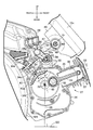
- FIG. 2 is an enlarged vertical sectional view of the internal combustion engine observed from the opposite side.
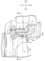
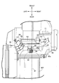
- FIG. 3 is an enlarged plan view of the crankcase observed from above.
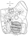
- FIG. 4 is an enlarged partial side view of the fan cover.
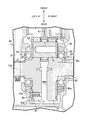
- FIG. 5 is an enlarged sectional view of a crankshaft.
- FIG. 6 is a partially enlarged plan view of the scooter corresponding to FIG. 3 and schematically showing the configuration of a fan cover and an air cleaner according to another embodiment.
- front and rear, right and left, and upper and lower mean directions as viewed from the rider of the motorcycle.
- FIG. 1 schematically shows the entire configuration of a scooter 11 which is a specific example of a saddle-ride type vehicle (motorcycle).
- the scooter 11 is provided with a body frame 12.
- the body frame 12 is formed of a head pipe 13, a down tube 14 extending downward from the head pipe 13, and a pair of left and right side frames 15 extending rearward from the lower end of the down tube 14.
- a front fork 16 and a steering handle 17 are rotatably supported by the head pipe 13.
- the front fork 16 supports a front wheel WF rotatably around an axle 18.
- the side frame 15 includes a down frame portion 15a extending downward from the lower end of the down tube 14, a lower frame portion 15b extending parallel to the ground from the rear end of the down frame portion 15a, and a rear end up from the rear end of the lower frame portion 15b. And a seat rail portion 15c extending above the rear wheel WR. An occupant seat 19 is supported on the seat rail portion 15c.
- the scooter 11 includes a body cover 21 that covers the body frame 12.
- a floor 22 is defined on the lower frame portion 15 b of the side frame 15 between the head pipe 13 and the passenger seat 19.
- the fuel tank 23 is supported by the lower frame portion 15 b below the floor 22.
- a storage box 24 is supported by the seat rail portion 15 c in the vehicle body cover 21. The storage box 24 is opened and closed by a passenger seat 19.
- a swing type power unit 25 is supported on the vehicle body frame 12 between the side frames 15 so as to be vertically swingable via a link mechanism 26.
- the power unit 25 is connected to the internal combustion engine 27 generating power based on the fuel supplied from the fuel tank 23, and the internal combustion engine 27, and transmits the power of the internal combustion engine 27 at a gear ratio linearly changing to the rear wheel WR.
- a transmission 28 is provided.
- a rear wheel WR is supported at the rear end of the power unit 25 so as to be rotatable about an axle 29.
- a rear cushion unit 31 is attached between the rear end of the power unit 25 and the rear end of the seat rail portion 15c.
- the power unit 25 has a function of a suspension device that connects the rear wheel WR to the vehicle body frame 12 in a swingable manner.
- An engine body 32 of the internal combustion engine 27 includes a crankcase 34 accommodating a crankshaft, which will be described later, rotatably about the rotation axis 33, and a cylinder block 35 coupled to the crankcase 34 and having the cylinder axis C inclined forward.
- a cylinder head 36 coupled to the cylinder block 35 and a head cover 37 coupled to the cylinder head 36 are provided.
- Connected to the cylinder head 36 are an intake system 38 for introducing an air-fuel mixture into the combustion chamber and an exhaust system 39 for discharging the gas after combustion from the combustion chamber.
- the transmission 28 includes a continuously variable transmission (not shown) housed in a transmission case 41 integrated with the crankcase 34 of the engine body 32.
- the intake system 38 includes an intake pipe 42 connected to an intake passage (not shown) formed in the cylinder head 36, a throttle body 43 connected to the intake pipe 42, and an air cleaner 44 connected to the throttle body 43. And Air is introduced from the air cleaner 44 and filtered by the air cleaner 44. Fuel is injected from the combustion injection valve to the air by the throttle body 43 to generate an air-fuel mixture. The air-fuel mixture is supplied to the intake passage through the intake pipe 42.
- the link mechanism 26 includes a cross member 45 extending in the vehicle width direction above the crankcase 34 in the lateral direction.
- the cross members 45 are connected at both ends to the brackets 46 fixed to the left and right seat rail portions 15 c respectively.
- the cross member 45 is composed of a pipe of circular cross section.
- mounting members 47 are fixed to both ends of the cross member 45.
- the mounting member 47 is pivotably connected to the bracket 46 around a rotational axis Xr parallel to the axial center of the axle 29.
- the mounting member 47 is formed with a cylindrical body 49 coaxially surrounding a rocking shaft 48 fixed to the bracket 46.
- a damper member 51 such as rubber is sandwiched between the swing shaft 48 and the cylindrical body 49.
- the cross member 45 is formed with a linear region 45 a extending parallel to the axle 29 at a center position in the vehicle width direction.
- a connector 52 that slopes forward and downward is fixed.
- the connector 51 is displaced forward as it goes downward in the direction of gravity.
- the link mechanism 26 includes a shaft 53 disposed above the crankcase 34 and having an axis parallel to the axis of the axle 29.
- the shaft 53 is fixed to a pair of left and right projecting pieces (links) 54 protruding upward from the top of the crankcase 34.
- a long cylinder 55 fixed to the connector 52 is rotatably connected to the shaft 53 around the axial center of the shaft 53.
- the internal combustion engine 27 includes a piston 57 incorporated in the cylinder block 35.
- the piston 57 is accommodated in a cylinder 58 which has a forwardly inclined cylinder axis C and is divided into the cylinder block 35.
- the cylinder block 35 is formed with a single cylinder 58 that receives a single piston 57.
- a combustion chamber 49 is defined between the piston 57 and the cylinder head 36.
- An air-fuel mixture is introduced into the combustion chamber 49 from the intake passage.
- the piston 57 reciprocates along the cylinder axis C.
- One end of a connecting rod 61 is connected to the piston 57.
- the other end of the connecting rod 61 is connected to the crankshaft 62 in the crankcase 34.
- the linear movement of the piston 57 along the cylinder axis C is converted to the rotational movement of the crankshaft 62 by the action of the connecting rod 61.
- the internal combustion engine 27 is connected to the crankshaft 62 coaxially with the rotation axis 33, and faces an annular path of the annular plate-shaped pulsar ring (target body) 63 and the annular track of the pulsar ring 63 that integrally rotates with the crankshaft 62. And a pulser sensor (detection sensor) 64 that generates a pulse signal in accordance with the movement of the pulser ring 63.
- the pulsar ring 63 includes a plurality of reluctors (gear teeth) 53 a arranged annularly at equal intervals around the rotation axis 33.
- the relaxor 63a is disposed, for example, at every central angle of 10 degrees.
- the retractor 63a is made of, for example, a magnetic material.
- the pulsar sensor 64 is inserted from the outside into a sensor hole 34 c drilled in the crankcase 34 and attached to the crankcase 34.
- the sensor hole 34 c is located above one horizontal plane including the rotation axis 33 of the crankshaft 62.
- the pulsar sensor 64 faces the crank chamber 34b at the tip for detecting the magnetic substance.
- the pulsar sensor 64 outputs an electrical signal in accordance with the presence or absence of the magnetic substance detected on the trajectory of the pulsar ring 63.
- the pulsar sensor 64 outputs a pulse signal that specifies the angular position of the crankshaft 62.
- an eddy current type micro displacement sensor may be used as the pulsar sensor 64.
- the pulsar sensor 64 is disposed to the rear of the projecting portion (link portion) 54 and to the front of the rear wheel WR in a side view of the vehicle according to the forward inclination posture of the cylinder axis C.
- the pulsar sensor 64 is located below the fender portion 44 a formed on the air cleaner 44. Details of the fender portion 44a will be described later.
- the pulsar sensor 64 is held in an inclined posture with respect to the vehicle vertical direction (gravity acceleration direction) orthogonal to the ground GD.
- the detection axis 64a is directed to the rotation axis 33 of the crankshaft 62, and is inclined at an inclination angle ⁇ around the rotation axis 33 from a virtual plane 66 including the rotation axis 33 and the direction of gravitational acceleration.
- the pulsar sensor 64 is disposed offset in the vehicle width direction with respect to the central surface 67 of the rear wheel WR orthogonal to the axle of the rear wheel WR.
- the center plane 67 constitutes, for example, a symmetrical plane of symmetry with respect to the rear wheel WR (in particular, the tire).
- the fender portion 44a of the air cleaner 44 extends from the main body of the air cleaner 44 in the vehicle width direction, and is located below the seat rail portion 15c and above the rear wheel WR.
- the rear wheel WR is covered with the fender portion 44 a of the air cleaner 44 from above.
- a fan cover 68 is coupled to the crankcase 34. As shown in FIG. 4, the fan cover 68 may be fastened to the crankcase 34 by bolts 69. The fan cover 68 covers the cooling fan 71. A cooling fan 71 is coupled to one end of the crankshaft 62.
- the fan cover 68 is formed with a connecting portion 68 a extending toward the air cleaner 44 along the outer diameter of the rear wheel WR.
- the fan cover 68 is connected to the air cleaner 44 at the tip of the connection portion 68 a.
- the pulsar sensor 64 overlaps the connecting portion 68 a of the fan cover 68 in a side view.
- the pulsar sensor 64 is covered by a fan cover 68 from the side.
- the cooling fan 71 includes a rotating body 72 attached to the crankshaft 62.
- the rotor 72 has a circular contour concentric with the axis of rotation 33.
- a plurality of blades 73 are disposed on the surface of the rotating body 72.
- the cooling fan 71 is configured as a centrifugal fan.
- the fan cover 68 is formed with a circular opening 74 concentric with the rotation axis 33.
- a variable louver 75 is installed in the opening 74.
- the opening area of the opening 74 is changed by the action of the variable louver 75.
- the crankshaft 62 is coupled to a first crank web 77 having a first shaft 77a and a first crank web 77, and has a disk shape having a second shaft 78a.
- a second crank web 78 and a crank pin 79 coaxially connecting the first shaft 77a and the second shaft 78a and connecting the first crank web 77 and the second crank web 78 to each other are provided.
- the tip of the connecting rod 61 is connected to the crank pin 79 so as to be rotatable about a rotation axis parallel to the axis of the first shaft 77a and the second shaft 78a.
- the first shaft 77 a of the first crank web 77 is rotatably supported by the first half 82 of the crankcase 34 via the first bearing 81.
- the second shaft 78 a of the second crank web 78 is rotatably supported by the second half 84 of the crankcase 34 via a second bearing 83.
- the first half 82 and the second half 84 are combined to constitute the crankcase 34.
- the first surface 85a of the first crank web 77 is formed with a flat surface 86 extending in a virtual plane perpendicular to the axis of the first shaft 77a along a circular outer periphery.
- Pulsar ring 63 is superimposed on flat surface 86.
- the retractor 63 a of the pulsar ring 63 protrudes radially beyond the outer periphery of the first crank web 77 at least at the radially outer end.
- the pulsar ring 63 is fastened to the first crank web 77 with a screw 87.
- the inner diameter of the pulsar ring 63 is larger than that of the first bearing 81.
- the first shaft 77a is connected to the first surface 85a of the first crank web 77 at an enlarged diameter portion 88 having a diameter larger than that of the first shaft 77a.
- the first bearing 81 is attached to the enlarged diameter portion 88.
- the first bearing 81 is pressed against the first surface 85 a of the first crank web 77. Therefore, the pulsar ring 63 is disposed radially outward of the first bearing 81.
- the second crank web 78 faces the first crank web 77 at the second surface 89 b on the back side of the first surface 89 a.
- the second shaft 78a is connected to the first surface 89a of the second crank web 78 at an enlarged diameter portion 91 having a diameter larger than that of the second shaft 78a.
- the second bearing 83 is attached to the enlarged diameter portion 91. The second bearing 83 is pressed against the first surface 89 a of the second crank web 78.
- the pulsar ring 63 rotates integrally with the crankshaft 62.
- the retractor 63 a of the pulsar ring 63 moves around the rotation axis 33 along an annular orbit coaxial with the rotation axis 33.
- the pulser sensor 64 alternately faces the reactor 63a and the space, detects the magnetic substance of the reactor 63a, and generates a pulse signal. Since the retractors 63a are arranged at equal intervals, the time intervals of the pulses change corresponding to the angular velocity.
- the detection axis 64 a of the pulsar sensor 64 is located within a range of ⁇ 45 degrees around the rotation axis 33 of the crankshaft 62 with respect to the virtual plane 65 orthogonal to the cylinder axis C. Therefore, when the piston 57 reciprocates, the distance between the tip of the pulsar sensor 64 and the reactor 63a of the pulsar ring 63 is not easily influenced by the reciprocation. Thus, the pulsar sensor 64 is disposed in a layout that is not easily affected by the reciprocating motion of the piston 57, and the pulsar sensor 64 can accurately detect the motion of the pulsar ring 63.
- the detection axis 64 a of the pulsar sensor 64 is directed to the rotation axis 33 of the crankshaft 62, and is tilted around the rotation axis 33 from the imaginary plane 66 including the rotation axis 33 and the gravity acceleration direction. In this way, since the pulsar sensor 64 is disposed in the inclined posture, the protrusion of the pulsar sensor 64 in the height direction with respect to the gravity acceleration direction is suppressed. In particular, since the pulsar sensor 64 is disposed on the upper side of the crankcase 34, the pulsar sensor 64 can be disposed without interfering with vehicle parts.
- the pulsar sensor 64 is disposed below the link mechanism 26, it is inclined with respect to the vehicle vertical direction (weight acceleration direction) orthogonal to the ground GD, corresponding to the forward and downward connecting body 52. Interference between the link mechanism 26 and the pulsar sensor 64 can be avoided.
- the pulsar sensor 64 is disposed rearward of the projecting piece 54 of the crankcase 34 and forward of the rear wheel WR. Therefore, it is possible to protect the front and rear with vehicle parts without providing a protective cover on the pulsar sensor 64. Since the vehicle parts also serve as protective members for the pulsar sensor 64, an increase in manufacturing costs can be avoided.
- the pulsar sensor 64 is disposed offset in the vehicle width direction with respect to the center plane 67 of the rear wheel WR orthogonal to the axle 29 of the rear wheel WR.
- water on the road surface is bounced up along the center of the rotating rear wheel WR in the vehicle width direction.
- the splashed water droplets do not hit the pulsar sensor 64. In this way, it is possible to make it difficult for water droplets to hit the detection sensor.
- the air cleaner 44 is formed with a fender portion 44 a that covers the rear wheel WR.
- the pulsar sensor 64 is located below the fender portion 44a.
- the pulsar sensor 64 is efficiently disposed in the space formed between the rear wheel WR and the fender portion 44 a of the air cleaner 44. Also, the pulsar sensor 64 is protected from above by the air cleaner 44. Water droplets splashed up from the rear wheel WR can be made less likely to be applied to the pulsar sensor 64.
- the pulsar sensor 64 overlaps with the fan cover 68 covering the cooling fan 71 coupled to the crankcase 34 and coupled to one end of the crankshaft 62 in a side view. Since the pulser sensor 64 is structured to be covered by the fan cover 68 from the side, the pawl sensor 64 is protected from the side. In addition, the appearance can be improved because it is not viewed in a side view.
- a bridge member 92 may be disposed between the fan cover 68 and the air cleaner 44 to connect the fan cover 68 and the air cleaner 44.
- the fender portion 44a may be omitted from the air cleaner 44. Since the fan cover 68, the air cleaner 44, and the cross-linking member 92 are all molded from a resin material, the vibrations of the fan cover 68 and the air cleaner 44 are mutually reduced when the power unit 25 swings. it can.
Landscapes
- Engineering & Computer Science (AREA)
- Chemical & Material Sciences (AREA)
- Combustion & Propulsion (AREA)
- Mechanical Engineering (AREA)
- General Engineering & Computer Science (AREA)
- Combined Controls Of Internal Combustion Engines (AREA)
- Cylinder Crankcases Of Internal Combustion Engines (AREA)
Abstract
Description
27…内燃機関
29…車軸
33…(クランクシャフトの)回転軸線
34…クランクケース
42…吸気管
44…エアクリーナー
44a…フェンダー部
54…リンク部(突片)
57…ピストン
58…シリンダー
61…コンロッド
62…クランクシャフト
63…被検知体(パルサーリング)
64…検知センサー(パルサーセンサー)
64a…軸線(検出軸線)
65…(直交する)仮想平面
66…(重力加速度方向を含む)仮想平面
67…(後輪の)中央面
68…ファンカバー
71…冷却ファン
C…シリンダー軸線
WR…後輪
Claims (6)
- シリンダー(58)に収容されてシリンダー軸線(C)に沿って往復運動するピストン(57)と、
前記ピストン(57)に接続されたコンロッド(61)と、
前記コンロッド(61)に接続されたクランクシャフト(62)と、
前記クランクシャフト(62)と一体に回転する被検知体(63)と、
前記被検知体(63)の軌道に向き合わせられて、前記被検知体(63)の動きに応じてパルス信号を生成する検知センサー(64)と、を備える内燃機関(27)において、
前記検知センサー(64)の軸線(64a)は、前記シリンダー軸線(C)に直交する仮想平面(65)に対して、前記クランクシャフト(62)の回転軸線(33)回りで±45度の範囲に位置する
ことを特徴とする内燃機関。 - 請求項1に記載の内燃機関において、
前記クランクシャフト(62)を収容し、前記回転軸線(33)回りで回転自在に前記クランクシャフト(62)を支持するクランクケース(34)をさらに備え、
前記検知センサー(64)の前記軸線(64a)は、前記クランクシャフト(62)の前記回転軸線(33)を指向し、前記回転軸線(33)および重力加速度方向を含む仮想平面(66)から前記回転軸線(33)回りで傾く
ことを特徴とする内燃機関。 - 請求項2に記載の内燃機関において、
前記クランクケース(34)に形成されて、後輪(WR)の前方で車体フレーム(12)に連結されるリンク部(54)をさらに備え、
前記検知センサー(64)は、前記リンク部(54)の後方であって前記後輪(WR)の前方に配置される
ことを特徴とする燃機関。 - 請求項3に記載の内燃機関において、前記後輪(WR)の車軸(29)に直交する前記後輪(WR)の中央面(67)に対して、前記検知センサー(64)は車幅方向にオフセットして配置される
ことを特徴とする内燃機関。 - 請求項3または4に記載の内燃機関において、
前記検知センサー(64)は、吸気管(42)に接続されるエアクリーナー(44)に形成されて前記後輪(WR)の上方を覆うフェンダー部(44a)の下方に位置する
ことを特徴とする内燃機関。 - 請求項2~5のいずれか1項に記載の内燃機関において、
前記検知センサー(64)は、側面視で、前記クランクケース(34)に結合されて前記クランクシャフト(62)の一端に結合される冷却ファン(71)を覆うファンカバー(68)と重なる
ことを特徴とする内燃機関。
Priority Applications (4)
| Application Number | Priority Date | Filing Date | Title |
|---|---|---|---|
| BR112019019950A BR112019019950A2 (pt) | 2017-03-30 | 2018-03-15 | motor de combustão interna |
| JP2019509260A JP6714771B2 (ja) | 2017-03-30 | 2018-03-15 | 内燃機関 |
| EP18777550.7A EP3604781A4 (en) | 2017-03-30 | 2018-03-15 | INTERNAL COMBUSTION ENGINE |
| CN201880022694.5A CN110475960B (zh) | 2017-03-30 | 2018-03-15 | 内燃机 |
Applications Claiming Priority (2)
| Application Number | Priority Date | Filing Date | Title |
|---|---|---|---|
| JP2017068892 | 2017-03-30 | ||
| JP2017-068892 | 2017-03-30 |
Publications (1)
| Publication Number | Publication Date |
|---|---|
| WO2018180560A1 true WO2018180560A1 (ja) | 2018-10-04 |
Family
ID=63675683
Family Applications (1)
| Application Number | Title | Priority Date | Filing Date |
|---|---|---|---|
| PCT/JP2018/010297 Ceased WO2018180560A1 (ja) | 2017-03-30 | 2018-03-15 | 内燃機関 |
Country Status (5)
| Country | Link |
|---|---|
| EP (1) | EP3604781A4 (ja) |
| JP (1) | JP6714771B2 (ja) |
| CN (1) | CN110475960B (ja) |
| BR (1) | BR112019019950A2 (ja) |
| WO (1) | WO2018180560A1 (ja) |
Cited By (1)
| Publication number | Priority date | Publication date | Assignee | Title |
|---|---|---|---|---|
| WO2021002236A1 (ja) | 2019-07-01 | 2021-01-07 | 本田技研工業株式会社 | 内燃機関構造 |
Citations (6)
| Publication number | Priority date | Publication date | Assignee | Title |
|---|---|---|---|---|
| JP2002371906A (ja) | 2001-06-13 | 2002-12-26 | Nippon Soken Inc | 内燃機関の失火判定装置 |
| JP2004019482A (ja) * | 2002-06-13 | 2004-01-22 | Aisan Ind Co Ltd | 内燃機関の行程判別方法および行程判別装置 |
| JP2010038017A (ja) * | 2008-08-04 | 2010-02-18 | Yamaha Motor Co Ltd | 燃料噴射制御装置およびそれを備えた車両 |
| JP2014199040A (ja) | 2013-03-29 | 2014-10-23 | 本田技研工業株式会社 | エンジン制御装置 |
| WO2015050155A1 (ja) * | 2013-10-01 | 2015-04-09 | 株式会社ミツバ | エンジン始動制御装置 |
| JP2015143488A (ja) * | 2014-01-31 | 2015-08-06 | 本田技研工業株式会社 | 鞍乗型車両用内燃機関の冷却装置 |
Family Cites Families (18)
| Publication number | Priority date | Publication date | Assignee | Title |
|---|---|---|---|---|
| JP2876885B2 (ja) * | 1992-04-10 | 1999-03-31 | トヨタ自動車株式会社 | 内燃機関のクランク角位置検出装置 |
| JPH10299537A (ja) * | 1997-04-28 | 1998-11-10 | Mazda Motor Corp | 筒内噴射型火花点火式エンジン |
| JP4145520B2 (ja) * | 2001-11-19 | 2008-09-03 | 本田技研工業株式会社 | 内燃機関のカム位相制御装置 |
| JP2003343297A (ja) * | 2002-03-20 | 2003-12-03 | Honda Motor Co Ltd | エンジン |
| JP4057852B2 (ja) * | 2002-06-26 | 2008-03-05 | 本田技研工業株式会社 | 自動二輪車用パワーユニット |
| JP4217089B2 (ja) * | 2003-03-19 | 2009-01-28 | 本田技研工業株式会社 | エンジン |
| JP4060226B2 (ja) * | 2003-04-01 | 2008-03-12 | 本田技研工業株式会社 | 内燃機関におけるノックセンサの取付構造 |
| JP2004353508A (ja) * | 2003-05-28 | 2004-12-16 | Petroliam Nasional Bhd | エンジンにおけるセンサー取付部構造 |
| JP4373908B2 (ja) * | 2004-12-28 | 2009-11-25 | 本田技研工業株式会社 | 内燃機関の失火検出装置 |
| JP4602213B2 (ja) * | 2005-09-30 | 2010-12-22 | 本田技研工業株式会社 | 内燃機関のバランサ機構 |
| JP4766563B2 (ja) * | 2006-09-29 | 2011-09-07 | 本田技研工業株式会社 | 車両用発電装置 |
| JP4339347B2 (ja) * | 2006-10-30 | 2009-10-07 | 本田技研工業株式会社 | 内燃機関のクランク角速度検出装置 |
| JP2009057878A (ja) * | 2007-08-31 | 2009-03-19 | Yamaha Motor Co Ltd | エンジンおよび鞍乗型車両 |
| WO2012105308A1 (ja) * | 2011-02-04 | 2012-08-09 | ヤマハ発動機株式会社 | エンジン、及び当該エンジンを搭載した鞍乗型車両 |
| US8667937B2 (en) * | 2011-03-07 | 2014-03-11 | Caterpillar Inc. | Apparatus for sensing cam phaser position |
| JP2013024099A (ja) * | 2011-07-20 | 2013-02-04 | Yamaha Motor Co Ltd | 内燃機関およびそれを備えた鞍乗型車両 |
| JP2013024100A (ja) * | 2011-07-20 | 2013-02-04 | Yamaha Motor Co Ltd | 内燃機関およびそれを備えた鞍乗型車両 |
| JP2014105626A (ja) * | 2012-11-27 | 2014-06-09 | Yamaha Motor Co Ltd | 鞍乗り型車両 |
-
2018
- 2018-03-15 BR BR112019019950A patent/BR112019019950A2/pt active Search and Examination
- 2018-03-15 WO PCT/JP2018/010297 patent/WO2018180560A1/ja not_active Ceased
- 2018-03-15 EP EP18777550.7A patent/EP3604781A4/en not_active Withdrawn
- 2018-03-15 JP JP2019509260A patent/JP6714771B2/ja not_active Expired - Fee Related
- 2018-03-15 CN CN201880022694.5A patent/CN110475960B/zh active Active
Patent Citations (6)
| Publication number | Priority date | Publication date | Assignee | Title |
|---|---|---|---|---|
| JP2002371906A (ja) | 2001-06-13 | 2002-12-26 | Nippon Soken Inc | 内燃機関の失火判定装置 |
| JP2004019482A (ja) * | 2002-06-13 | 2004-01-22 | Aisan Ind Co Ltd | 内燃機関の行程判別方法および行程判別装置 |
| JP2010038017A (ja) * | 2008-08-04 | 2010-02-18 | Yamaha Motor Co Ltd | 燃料噴射制御装置およびそれを備えた車両 |
| JP2014199040A (ja) | 2013-03-29 | 2014-10-23 | 本田技研工業株式会社 | エンジン制御装置 |
| WO2015050155A1 (ja) * | 2013-10-01 | 2015-04-09 | 株式会社ミツバ | エンジン始動制御装置 |
| JP2015143488A (ja) * | 2014-01-31 | 2015-08-06 | 本田技研工業株式会社 | 鞍乗型車両用内燃機関の冷却装置 |
Non-Patent Citations (1)
| Title |
|---|
| See also references of EP3604781A4 |
Cited By (1)
| Publication number | Priority date | Publication date | Assignee | Title |
|---|---|---|---|---|
| WO2021002236A1 (ja) | 2019-07-01 | 2021-01-07 | 本田技研工業株式会社 | 内燃機関構造 |
Also Published As
| Publication number | Publication date |
|---|---|
| EP3604781A4 (en) | 2020-04-08 |
| CN110475960A (zh) | 2019-11-19 |
| BR112019019950A2 (pt) | 2020-04-28 |
| JPWO2018180560A1 (ja) | 2020-01-23 |
| EP3604781A1 (en) | 2020-02-05 |
| JP6714771B2 (ja) | 2020-06-24 |
| CN110475960B (zh) | 2022-02-25 |
Similar Documents
| Publication | Publication Date | Title |
|---|---|---|
| JP6613092B2 (ja) | 鞍乗型車両 | |
| US7032563B2 (en) | Intake apparatus for engine | |
| JP6714771B2 (ja) | 内燃機関 | |
| JP6487959B2 (ja) | 内燃機関 | |
| CN110520614B (zh) | 内燃机 | |
| CN110475957B (zh) | 内燃机 | |
| JP6836653B2 (ja) | 内燃機関 | |
| JP6795644B2 (ja) | スイングユニット式のパワーユニット | |
| JP5869398B2 (ja) | 自動二輪車における傾斜角検出手段の取付構造 | |
| JP6706385B2 (ja) | 内燃機関 | |
| JP6902072B2 (ja) | 車両用パワーユニット | |
| EP3992441B1 (en) | Internal combustion engine structure | |
| JP6714770B2 (ja) | 内燃機関 | |
| JP2019171994A (ja) | パワーユニット | |
| BR112019020196B1 (pt) | Motor de combustão interna | |
| JP2019132361A (ja) | クランクシャフトおよびその製造方法 |
Legal Events
| Date | Code | Title | Description |
|---|---|---|---|
| 121 | Ep: the epo has been informed by wipo that ep was designated in this application |
Ref document number: 18777550 Country of ref document: EP Kind code of ref document: A1 |
|
| ENP | Entry into the national phase |
Ref document number: 2019509260 Country of ref document: JP Kind code of ref document: A |
|
| NENP | Non-entry into the national phase |
Ref country code: DE |
|
| REG | Reference to national code |
Ref country code: BR Ref legal event code: B01A Ref document number: 112019019950 Country of ref document: BR |
|
| ENP | Entry into the national phase |
Ref document number: 2018777550 Country of ref document: EP Effective date: 20191030 |
|
| ENP | Entry into the national phase |
Ref document number: 112019019950 Country of ref document: BR Kind code of ref document: A2 Effective date: 20190924 |