WO2018180910A1 - Dispositif d'évacuation - Google Patents
Dispositif d'évacuation Download PDFInfo
- Publication number
- WO2018180910A1 WO2018180910A1 PCT/JP2018/011479 JP2018011479W WO2018180910A1 WO 2018180910 A1 WO2018180910 A1 WO 2018180910A1 JP 2018011479 W JP2018011479 W JP 2018011479W WO 2018180910 A1 WO2018180910 A1 WO 2018180910A1
- Authority
- WO
- WIPO (PCT)
- Prior art keywords
- discharge
- hole
- discharge plate
- water tank
- side wall
- Prior art date
- Legal status (The legal status is an assumption and is not a legal conclusion. Google has not performed a legal analysis and makes no representation as to the accuracy of the status listed.)
- Ceased
Links
Images






Classifications
-
- C—CHEMISTRY; METALLURGY
- C02—TREATMENT OF WATER, WASTE WATER, SEWAGE, OR SLUDGE
- C02F—TREATMENT OF WATER, WASTE WATER, SEWAGE, OR SLUDGE
- C02F1/00—Treatment of water, waste water, or sewage
- C02F1/48—Treatment of water, waste water, or sewage with magnetic or electric fields
-
- F—MECHANICAL ENGINEERING; LIGHTING; HEATING; WEAPONS; BLASTING
- F24—HEATING; RANGES; VENTILATING
- F24F—AIR-CONDITIONING; AIR-HUMIDIFICATION; VENTILATION; USE OF AIR CURRENTS FOR SCREENING
- F24F6/00—Air-humidification, e.g. cooling by humidification
Definitions
- the present invention relates to a discharge device.
- Patent Document 1 discloses this type of discharge device.
- the discharge device of Patent Document 1 includes one water tank and a partition plate that divides the inside of the water tank into a first chamber and a second chamber.
- a first electrode is provided in the water in the first chamber, and a second electrode is provided in the water in the second chamber.
- the partition plate of Patent Document 1 holds a discharge plate having fine holes (discharge holes). The first chamber and the second chamber communicate with each other through this hole.
- the partition plate is detachably attached to the inside of the water tank. Further, the partition plate is configured to be splittable in the thickness direction, and the partition plate is held between the two split bodies. With this structure, only the discharge plate can be detached independently by removing the partition plate from the water tank and dividing the partition plate. Therefore, maintenance and replacement of the discharge plate can be performed easily.
- the partition plate is configured to be detachable from the water tank as described above, the outer peripheral edge portions (left and right side edge portions and lower edge portions) of the partition plate are interposed in the two chambers. And the distance of the clearance gap around a partition plate is comparatively short. For this reason, when the seal
- the present invention has been made paying attention to such a problem, and the purpose of the discharge is to enable the discharge plate to be easily removed and to prevent water leakage between the first chamber and the second chamber. It is to propose a device.
- the first invention comprises a power source (90), two electrodes (91, 94) connected to the power source (90), Side walls (26, 36) in which chambers (22, 32) for storing water conducting to each electrode (91, 94) and communication holes (28, 38) communicating with the chambers (22, 32) are formed.
- Each having two water tanks (21, 31) and a discharge plate (50) having a hole (52) for generating a discharge, and the two water tanks (21, 31) have two side walls ( 26, 36) are connected to each other in a state where the discharge plate (50) is sandwiched so that the two communication holes (28, 38) communicate with the hole (52). It is.
- the discharge plate (50) may be directly sandwiched between the two side walls (26, 36) so as to be in contact with the two side walls (26, 36). 36) may be indirectly sandwiched via another member.
- the discharge plates (50) are connected to each other with the discharge plates (50) sandwiched between the side walls (26, 36) of the two water tanks (21, 31).
- each chamber (22, 32) of each water tank (21, 31) communicates with the hole (52) via each communication hole (28, 38).
- a voltage is applied to each electrode from the power supply (90)
- a current flows from one chamber (22, 32) to the other chamber (22, 32), and the current density in the hole (52) increases.
- bubbles are generated inside the hole (52), and as a result, discharge is performed inside the hole (52).
- the discharge plate (50) is sandwiched and held between two water tanks (21, 31). That is, the side walls (26, 36) of each water tank (21, 31) also serve as a holding member for sandwiching the discharge plate (50).
- the periphery of the partition plate does not face the two chambers, and water does not leak around the partition plate.
- the discharge plate (50) can be removed from the discharge device (10) by releasing the connection between the water tanks (21, 31) and separating them.
- the discharge plate (50) includes a disc-shaped discharge plate main body (51) in which the hole (52) is formed, and the discharge plate main body (51) inside.
- a disc-shaped elastic member (60) having a through hole (61) for holding and exposing the hole (52) of the discharge plate main body (51) to the outside, the two water tanks (21, 31),
- the discharge device is characterized in that the two side walls (26, 36) are configured to be connected to each other with the elastic member (60) sandwiched therebetween.
- the elastic member (60) may be directly sandwiched between the side walls (26, 36) so as to be in contact with the two side walls (26, 36), or the two side walls (26, 36). It may be sandwiched indirectly via other members.
- the discharge plate (50) of the second invention the discharge plate body (51) in which the hole (52) is formed is covered with a disk-shaped elastic member (60), and the elastic member (60) has two side walls. (26,36). For this reason, even if the discharge plate (50) is vibrated due to discharge or the like, the stress concentration acting on the discharge plate (50) can be relaxed by the elastic member (60). As a result, it is possible to prevent the discharge plate (50) from being cracked due to vibration.
- the periphery of the discharge plate (50) can be sealed by bringing the elastic member (60) into close contact with the side walls (26, 36) and the outer surfaces of other members. That is, water that has passed through the communication hole (28, 38) from one chamber (22, 32) may wrap around the discharge plate (50) and leak into the other chamber (22, 32). There is. However, such a water leak can be avoided by bringing the elastic member (60) into close contact with the side walls (26, 36) and other members.
- At least one of the side end faces (60a, 60b) on both sides in the axial direction of the elastic member (60) has an annular projection surrounding the through hole (61).
- the discharge unit is characterized in that (65, 66, 67, 68) is formed.
- the annular protrusions (65, 66, 67, 68) of the elastic member (60) are brought into contact with the side walls (26, 36) of the water tank (21, 31) or other members to form an annular shape.
- the seal portion is formed.
- the first annular protrusion (65, 66, 67, 68) and the first annular protrusion (65, 66, 67, 68) are formed on the side end surfaces (60a, 60b) of the elastic member (60). And a second annular projection (65, 66, 67, 68) surrounding the annular projection (65, 66, 67, 68).
- the two annular protrusions (65, 66, 67, 68) of the elastic member (60) are in contact with the side walls (26, 36) of the water tank (21, 31) or other members, respectively.
- two annular seal portions are formed. Thereby, the water in one chamber (22, 32) can be prevented from leaking into the other chamber (22, 32) by the two seal portions.
- the elastic member (60) is provided on at least one of the side walls (36) of the two water tanks (21, 31).
- the discharge device is characterized in that a recess (41) to be internally fitted is formed.
- the elastic plate (60) is fitted into the recess (41) formed in the side wall (36) of the water tank (31), so that the discharge plate (50) is attached to the two side walls (26, 36). It can be securely held in between.
- the side wall (36) in which the concave portion (41) is formed is constituted by a separate member separable from the main body (31a) of the corresponding water tank (31). It is the discharge device characterized by this.
- the side wall (36) in which the recess (41) is formed and the main body (31a) of the water tank (31) can be separated.
- the communication hole (38) and the recess (41) are formed in the side wall (36)
- the processing of the side wall (36) is performed. It becomes difficult. Specifically, for example, it is difficult to integrally form the communication hole (38) and the recess (41) of the side wall (36) together with the wall and bottom of the water tank (31) with a mold or the like.
- the communication hole (38) and the recess (41) of the side wall (36) are also easily formed. it can.
- a resin case (70) having a shape along an outer shape of the elastic member (60) is provided, and a side wall of each of the water tanks (21, 31). (26, 36) is formed integrally with the main body (21a, 31a) of the corresponding water tank (21, 31), and the resin case (70) is sandwiched between the two side walls (26, 36). It is the discharge device characterized by this.
- the resin case (70) covering the elastic member (60) is between the two side walls (26, 36) integrated with the main body (21a, 31a) of each water tank (21, 31). Sandwiched between.
- the discharge plate (50) and the resin case (70) can be configured as an integral unit, and the outer shape of the unit can be simplified. For this reason, the shape of the side walls (26, 36) sandwiching the resin case (70) is not complicated. As a result, the resin case (70) can be held between the side walls (26, 36) while being integrally formed with the water tanks (21, 31).
- the discharge plate (50) since the discharge plate (50) is sandwiched between the side walls (26, 36) of the two water tanks (21, 31), water leakage occurs around the partition portion as in the conventional example. There is no. As a result, water leakage or current leakage between the chambers (22, 32) can be prevented, and stable discharge can be performed. Further, according to the present invention, the discharge plate (50) can be easily removed by releasing the connection between the two water tanks (21, 31). Therefore, replacement and maintenance of the discharge plate (50) can be easily performed.
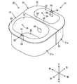
- FIG. 1 is a perspective view illustrating an overall configuration of a main part of a discharge device according to an embodiment.
- FIG. 2 is a top view of a main part of the discharge device according to the embodiment.
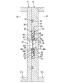
- FIG. 3 is a longitudinal sectional view of a main part of the discharge device according to the embodiment.
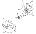
- FIG. 4 is an assembled perspective view of a main part of the discharge device according to the embodiment.
- FIG. 5 is a transverse cross-sectional view showing an assembled state of the discharge plate of the discharge device according to the embodiment.
- FIG. 6 is a perspective view in which a part of the discharge plate is broken.
- FIG. 7 is a diagram schematically showing the state of generation of bubbles in the holes of the discharge plate.
- FIG. 1 is a perspective view illustrating an overall configuration of a main part of a discharge device according to an embodiment.
- FIG. 2 is a top view of a main part of the discharge device according to the embodiment.
- FIG. 3 is a longitudinal sectional view of a main part
- FIG. 8 is a transverse cross-sectional view showing an assembled state of the discharge plate of the discharge device according to the first modification.
- FIG. 9 is an assembled perspective view of the main part of the discharge device according to the second modification.
- FIG. 10 is a transverse cross-sectional view illustrating an assembled state of the discharge plate of the discharge device according to the second modification.
- the discharge device is applied to, for example, a purified water generation device (10).
- the purified water generating device (10) generates purified water containing a purified component and a sterilizing factor along with the discharge.
- the produced purified water is used for cleaning and sterilizing an object (for example, dentures).
- the purified water generator (10) includes a tank unit (20), a power source (90), a first electrode (91), and a second electrode (94).
- the tank unit (20) includes a first water tank (21), a second water tank (31), a discharge plate (50), and a plurality of connecting members (bolts (15)). ing.
- the first water tank (21) and the second water tank (31) constitute a container whose upper side is opened.
- the first water tank (21) and the second water tank (31) are made of an insulating resin material, for example.
- the first water tank (21) is disposed on the left side
- the second water tank (31) is disposed on the right side.
- a 1st water tank (21) and a 2nd water tank (31) are connected with a some volt
- a first chamber (22) for storing water is formed in the first water tank (21), and a second chamber (32) for storing water is formed in the second water tank (31).
- the height of the first water tank (21) and the second water tank (31) is equal, and the volume of the first chamber (22) is larger than the volume of the second chamber (32).
- the front and rear lengths of the first chamber (22) are larger than the front and rear lengths of the second chamber (32), and the left and right widths of the first chamber (22) are the second chamber (32). It is larger than the left and right widths.
- the first water tank (21) includes a first bottom wall portion (23), a first peripheral wall portion (24) erected so as to surround the first bottom wall portion (23), and a first peripheral wall portion (24). And a first flange (25) continuous to the upper end.
- the first bottom wall (23) is formed in a substantially rectangular plate shape.
- a 1st surrounding wall part (24) is formed in a substantially rectangular cylinder shape.
- the first flange portion (25) is formed in a substantially rectangular frame shape that extends radially outward from the upper end of the first peripheral wall portion (24).
- the side wall facing the second water tank (31) in the first peripheral wall portion (24) constitutes the first side wall (26). Both end portions in the front-rear direction of the first side wall (26) are thicker than their intermediate portions. Fastening holes (27) to which the bolts (15) are fastened are formed in these thick portions (see FIG. 2). Each fastening hole (27) is formed to be recessed horizontally from the second water tank (31) side toward the left side. A thread groove into which the bolt (15) is screwed is formed on the inner peripheral surface of each fastening hole (27). A first communication hole (28) communicating with the first chamber (22) is formed in the central portion of the first side wall (26).
- the second water tank (31) includes a second bottom wall portion (33), a second peripheral wall portion (34) standing so as to surround the second bottom wall portion (33), and a second peripheral wall portion (34).
- the second bottom wall (33) is formed in a substantially rectangular plate shape.
- the second peripheral wall portion (34) is formed in a substantially rectangular cylindrical shape.
- the second flange portion (35) is formed in a substantially rectangular frame shape that extends radially outward from the upper end of the second peripheral wall portion (34).
- An insertion hole (37) for inserting the bolt (15) is formed in the front part and the rear part of the second peripheral wall part (34), respectively.
- Each insertion hole (37) is formed to be recessed horizontally from the right wall portion of the second water tank (31) toward the first water tank (21) side, and with the fastening hole (27) of the first water tank (21). Communicate.
- the side wall facing the first water tank (21) in the second peripheral wall portion (34) constitutes the second side wall (36).
- a second communication hole (38) communicating with the second chamber (32) is formed in the central portion of the second side wall (36).
- the discharge plate (50) is sandwiched between the first side wall (26) of the first water tank (21) and the second side wall (36) of the second water tank (31). Details of the discharge plate (50) will be described later.
- the power source (90) schematically shown in FIG. 3 applies a potential difference to the first electrode (91) and the second electrode (94).
- the power supply (90) of this embodiment applies a high voltage of an alternating waveform (square wave) in which positive and negative are switched with respect to the first electrode (91) and the second electrode (94). It is preferable that the duty ratio of the alternating waveform has the same ratio between the positive electrode side and the negative electrode side.
- the voltage applied from the power source (90) to the first electrode (91) and the second electrode (94) is not limited to a square wave, and may be, for example, a sine wave.
- the first electrode (91) is provided near the left side wall of the first water tank (21).
- the first electrode (91) of the present embodiment is configured by folding a thin metal plate.
- An intermediate portion between one end (upper end) and the other end (lower end) of the first electrode (91) is embedded in the first water tank (21).
- One end of the first electrode (91) is exposed to the upper side from the left side edge of the first flange (25).
- the exposed portion on one end side of the first electrode (91) constitutes a first energization section (92) that energizes the power source (90).
- the other end of the first electrode (91) is exposed from the inner wall side of the first peripheral wall portion (24) to the inside of the first chamber (22).
- the exposed part on the other end side of the first electrode (91) constitutes a first electrode part (93) immersed in the water of the first chamber (22).
- the 1st electrode part (93) of this embodiment exists in a position higher than the 1st communicating hole (28).
- the second electrode (94) is provided near the right side wall of the second water tank (31).
- the second electrode (94) of the present embodiment is configured by folding a thin metal plate.
- An intermediate portion between one end (upper end) and the other end (lower end) of the second electrode (94) is embedded in the second water tank (31).
- One end of the second electrode (94) is exposed to the upper side from the right edge of the second collar portion (35).
- the exposed part on the one end side of the second electrode (94) constitutes a second energization section (95) that energizes the power source (90).
- the other end of the second electrode (94) is exposed to the inside of the second chamber (32) from the inner wall side of the second peripheral wall portion (34).
- the exposed part on the other end side of the second electrode (94) constitutes a second electrode part (96) immersed in the water of the second chamber (32).
- the 2nd electrode part (96) of this embodiment exists in a position higher than the 2nd communicating hole (38), and exists in the same height position as the 1st electrode part (93).
- the discharge plate (50) shown in FIGS. 3 to 6 is held between the first side wall (26) and the second side wall (36).
- the discharge plate (50) includes a disc-shaped discharge plate body (51) and an elastic member (60) that covers the outer peripheral edge of the discharge plate body (51).
- the discharge plate body (51) is made of an insulating material (for example, a ceramic material).
- the elastic member (60) is made of an insulating resin material (for example, a silicon material) having elasticity.
- the discharge plate main body (51) is formed in a circular thin plate shape, and a fine circular hole (52) is formed in the axial center portion thereof.
- the thickness of the discharge plate body (51) is, for example, 0.5 mm, and the inner diameter of the hole (52) is, for example, 50 ⁇ m.
- the elastic member (60) is formed in a disk shape in which a through hole (61) is provided in the axial center.
- the elastic member (60) covers a portion of the discharge plate body (51) on the outer peripheral side of the hole (52). Specifically, a disk-shaped fitting groove (62) that extends radially outward from the through hole (61) is formed inside the elastic member (60). The outer peripheral edge of the elastic member (60) is fitted in the fitting groove (62).
- the elastic member (60) and the discharge plate body (51) are coaxial, and the through hole (61) and the hole (52) overlap in the axial direction. Therefore, the open ends on both sides of the hole (52) are exposed to the outside through the open ends of the through hole (61).
- the first taper portion (63) and the second taper portion (64) are formed in the through hole (61) of the elastic member (60).
- the first taper portion (63) is formed on the first side wall (26) side.
- the second taper portion (64) is formed on the second side wall (36) side.
- the first taper part (63) reduces the inner diameter of the through hole (61) as it approaches the discharge plate body (51) (right side).
- the second taper portion (64) reduces the inner diameter of the through hole (61) as it approaches the discharge plate body (51) (left side).
- a first inner protrusion (65) and a first intermediate protrusion (66) are formed on one (left side) first side end surface (60a) in the thickness direction of the elastic member (60).
- a second inner protrusion (67) and a second intermediate protrusion (68) are formed on the second (right) second side end face (60b) in the thickness direction of the elastic member (60).
- the first inner protrusion (65) and the second inner protrusion (67) constitute an annular first protrusion surrounding the through hole (61).
- the first intermediate protrusion (66) and the second intermediate protrusion (68) constitute an annular second protrusion that surrounds the first protrusion.
- the first inner protrusion (65) and the second inner protrusion (67) are formed in an annular shape along the inner edge of the through hole (61).
- the first inner protrusion (65) projects horizontally from the first side end face (60a) toward the first side wall (26).
- the second inner protrusion (67) protrudes horizontally from the second side end face (60b) toward the second side wall (36).
- the first intermediate protrusion (66) and the second intermediate protrusion (68) are formed at an intermediate portion between the outer edge and the inner edge of the elastic member (60).
- the first intermediate protrusion (66) is formed in an annular shape that is coaxial and parallel to the first inner protrusion (65).
- the second intermediate protrusion (68) is formed in an annular shape that is coaxial and parallel to the second inner protrusion (67).
- the first intermediate protrusion (66) protrudes horizontally from the first side end face (60a) toward the first side wall (26).
- the second intermediate protrusion (68) protrudes horizontally from the second side end face (60b) toward the second side wall (36).
- the 1st side wall (26) of this embodiment is formed integrally with the 1st main-body part (21a) of a 1st water tank (21).
- the 1st main-body part (21a) of this embodiment is a member except a 1st side wall (26) among 1st water tanks (21).
- the first communication hole (28) described above is formed in the first side wall (26).
- the first communication hole (28) includes, in order from the first chamber (22) toward the discharge plate main body (51), a first enlarged diameter portion (28a) and a first straight portion (28b).
- the first enlarged-diameter portion (28a) is formed in a substantially trapezoidal conical shape that increases the inner diameter as it approaches the first chamber (22).
- the first straight part (28b) is continuous with the end on the back side of the first enlarged diameter part (28a).
- the first straight portion (28b) forms a cylindrical inner peripheral surface having the same inner diameter across both ends in the axial direction.
- a first annular protrusion (29) is formed on the outer surface of the first side wall (26) so as to protrude toward the right side (second side wall (36)).
- the first annular protrusion (29) is formed in a substantially cylindrical shape along the inner edge of the first communication hole (28).
- a first inclined surface (29a) that is inclined with respect to the axial center of the first communication hole (28) is formed on the outer peripheral side of the first annular protrusion (29).
- the first inclined surface (29a) has a shape along the first tapered portion (63) of the elastic member (60).
- the 2nd side wall (36) of this embodiment is formed integrally with the 2nd main-body part (31a) of a 2nd water tank (31).
- the 2nd main-body part (31a) of this embodiment is a member except a 2nd side wall (36) among 2nd water tanks (31).
- the second communication hole (38) described above is formed in the second side wall (36).
- the second communication hole (38) includes, in order from the second chamber (32) toward the discharge plate main body (51), a second enlarged diameter portion (38a) and a second linear portion (38b).
- the second expanded diameter portion (38a) is formed in a substantially trapezoidal cone shape that expands the inner diameter as it approaches the second chamber (32).
- the second straight portion (38b) is continuous with the end on the back side of the second enlarged diameter portion (38a).
- the second straight portion (38b) forms a cylindrical inner peripheral surface having the same inner diameter across both ends in the axial direction.
- An annular recess (41) into which the elastic member (60) of the discharge plate (50) is fitted is formed on the outer surface of the second side wall (36).
- the annular recess (41) forms a substantially cylindrical space surrounding the second communication hole (38).
- a second annular convex portion (39) is formed on the bottom surface of the annular concave portion (41) so as to protrude toward the left side (first side wall (26)).
- the second annular protrusion (39) is formed in a substantially cylindrical shape along the inner edge of the second communication hole (38).
- a second inclined surface (39a) that is inclined with respect to the axial center of the second communication hole (38) is formed on the outer peripheral side of the second annular convex portion (39).
- the second inclined surface (39a) has a shape along the second tapered portion (64) of the elastic member (60).
- a ring groove (42) is formed on the outer surface of the second side wall (36).
- the ring groove (42) is formed in an annular shape formed around the annular recess (41).
- An annular O-ring (16) is fitted inside the ring groove (42).
- ⁇ Discharge plate assembly work> As shown in FIG. 4, in the assembly work, a first water tank (21), a second water tank (31), a discharge plate (50), and an O-ring (16) are prepared.
- the discharge plate (50) is in a state where an elastic member (60) is mounted around the discharge plate body (51).
- the O-ring (16) is fitted into the ring groove (42) of the second water tank (31), and the discharge plate (50) is fitted into the annular recess (41) of the second water tank (31).
- the second taper part (64) of the elastic member (60) is externally fitted to the second annular convex part (39) of the second water tank (31).
- first side wall (26) of the first water tank (21) and the second side wall (36) of the second water tank (31) are brought into contact with each other.
- first tapered portion (63) of the elastic member (60) is externally fitted to the first annular convex portion (29) of the first water tank (21).
- the first communication hole (28) of the first water tank (21) and the hole (52 of the discharge plate (50)) ) And the second communication hole (38) of the second water tank (31) are coaxial with each other so that they communicate with each other.
- ⁇ Driving operation> During operation of the purified water generator (10), water is stored in the first chamber (22) of the first water tank (21) and the second chamber (32) of the second water tank (31). Accordingly, the first electrode part (93) is immersed in the water of the first chamber (22), and the second electrode part (96) is immersed in the water of the second chamber (32). In this state, a square wave voltage is applied from the power source (90) to both electrodes (91, 94). Then, an electric current flows from one chamber (22, 32) to the other chamber (22, 32) through the hole (52).
- the first chamber (22) and the second chamber (32) are electrically separated by bubbles (B). That is, the bubble (B) functions as an insulation resistor that blocks conduction between the water in the first chamber (22) and the water in the second chamber (32).
- the interface corresponding to the first chamber (22) and the interface corresponding to the second chamber (32) are respectively pseudo electrodes, and the potential difference between these electrodes is Increase.
- dielectric breakdown occurs in the bubble (B) across the gas-liquid interface, and discharge occurs.
- purified water containing a purification component and a bactericidal factor active species such as hydroxyl radicals
- annular first gap (G1) is formed between the first inner protrusion (65) and the first intermediate protrusion (66), and the first gap (G1) is filled with air.
- first gap (G1) which is an air layer
- water inside the first inner protrusion (65) and water outside the first intermediate protrusion (66) are transferred to the first gap (G1). Intrusion can be prevented by air. Thereby, the sealing performance around the elastic member (60) is further improved.
- annular second gap (G2) is formed between the second inner protrusion (67) and the second inner protrusion (67), and the second gap (G2) is filled with air.
- the second gap (G2) which is an air layer, is formed in this way, water inside the second inner protrusion (67) and water outside the second intermediate protrusion (68) are transferred to the second gap (G2). Intrusion can be prevented by air. Thereby, the sealing performance around the elastic member (60) is further improved.
- the discharge plate (50) is sandwiched between the first side wall (26) of the first water tank (21) and the second side wall (36) of the second water tank (31). For this reason, water leakage does not occur around the partition plate as in the conventional structure in which the partition plate is attached to one water tank. Therefore, it is possible to reliably prevent a short circuit from occurring between the first chamber (22) and the second chamber (32) due to such water leakage, and it is possible to discharge stably. .
- the discharge plate (50) can be easily removed, and maintenance of the discharge plate (50) Exchanges can be made as appropriate.
- the fastening hole (27) for fastening the bolt (15) as the connecting member is outside the first chamber (22), and the insertion hole (37) for inserting the bolt (15) is also the second. It is outside the chamber (32). For this reason, there is no risk of water leakage in the fastening hole (27) or the insertion hole (37). Further, by fastening the bolt (15), the O-ring (16), the inner protrusions (65, 67), and the intermediate protrusions (66, 68) are compressed, and the sealing performance thereof can be improved.
- the elastic member (60) is provided with a plurality of annular protrusions (65, 66, 67, 68, 69), a plurality of seal portions can be formed around each communication hole (28, 38). Therefore, it can be avoided that water in one communication hole (28, 38) wraps around the elastic member (60) and leaks to the other communication hole (28, 38). A short circuit with the second chamber (32) can be reliably prevented. Moreover, the sealing performance around the elastic member (60) can be further improved by the air layer of the first gap (G1) and the second gap (G2).
- the discharge plate body (51) in which the hole (52) is formed is held by the tank unit (20) via the elastic member (60).
- the discharge plate body (51) When the discharge plate body (51) is vibrated due to discharge or other factors, the discharge plate body (51) may be broken. Since the discharge plate body (51) is extremely thin, such a problem becomes remarkable.
- an elastic member (60) having elasticity between the discharge plate main body (51) and the tank unit (20) the stress concentration of the discharge plate main body (51) accompanying vibration can be alleviated. Therefore, the discharge plate body (51) can be prevented from cracking.
- Modification 1 shown in FIG. 8, in the first water tank (21) of the above-described embodiment, the first main body (21a) and the first side wall (26) are configured as separate bodies (separate members). Moreover, in the modification 1, in the 2nd water tank (31) of the said embodiment, the 2nd main-body part (31a) and the 2nd side wall (36) are comprised by the different body (separate member). Other configurations are the same as those in the above embodiment.
- the shapes of the first side wall (26) and the second side wall (36) are relatively complicated. Specifically, a first enlarged diameter portion (28a) and a first straight portion (28b) are formed on the first side wall (26). Further, the second side wall (36) is formed with a second enlarged diameter portion (38a), a second straight portion (38b), an annular recess (41), and a ring groove (42).
- the 1st water tank (21) if the 1st side wall (26) is integrally formed with a metallic mold etc. with the 1st main part (21a), processing of the 1st water tank (21) will become difficult.
- the 2nd side wall (36) is integrally molded with a metal mold
- each water tank (21, 31) is a separate member from each main body (21a, 31a). For this reason, even if the shape of the first side wall (26) and the second side wall (36) becomes complicated, these can be formed relatively easily. Other functions and effects are the same as in the above embodiment.
- each main body part (21a, 31a) and each side wall (26, 36) can be integrally connected by adhesion, fusion, welding, fastening, or the like.
- the main body (21a, 31a) and the side wall (26, 36) of either one of the first water tank (21) and the second water tank (31) are configured as separate members, and the other main body ( 21a, 31a) and the side walls (26, 36) may be integrally formed.
- the modification 2 shown in FIG.9 and FIG.10 differs from the said embodiment by the point provided with the resin case (70) which covers a discharge plate (50).
- the resin case (70) includes a first divided body (71) near the first side wall (26) and a second divided body (81) near the second side wall (36), and these divided bodies (71 , 81) with the discharge plate (50) sandwiched between them. Therefore, by attaching the resin case (70) to the discharge plate (50), an integrated discharge plate unit (80) (discharge ASSY) can be configured.
- the discharge plate (50) is covered with the resin case (70) as described above, thereby simplifying the shapes of the first side wall (26) and the second side wall (36) as compared with the above embodiment. Is planned.
- the first divided body (71) is a disk-shaped resin member having a first case side communication hole (72) formed in the axial center thereof.
- the first case side communication hole (72) is formed coaxially with the first communication hole (28) and the hole (52), and communicates with the first communication hole (28) and the hole (52).
- a plurality of first fastening holes (73) are formed in the outer edge portion of the first divided body (71).
- the plurality of first fastening holes (73) penetrate the first divided body (71) in the axial direction and are arranged in the circumferential direction at an equal pitch.
- An annular first ring groove (74) is formed on the outer surface (the surface on the first side wall (26) side) of the first divided body (71).
- An annular first O-ring (17) is fitted inside the first ring groove (74).
- the first case-side annular recess (75) into which the elastic member (60) is fitted is formed on the inner side surface (the surface on the second side wall (36) side) of the first divided body (71).
- the first case-side annular recess (75) forms an annular or cylindrical space surrounding the first case-side communication hole (72).
- a first case-side annular convex portion (76) that protrudes toward the second side wall (36) is formed on the bottom surface of the first case-side annular concave portion (75.
- a first case-side inclined surface (77) that is inclined along the first tapered portion (63) of the elastic member (60) is formed on the outer peripheral side of the first case-side annular convex portion (76).
- the second divided body (81) is a disk-shaped resin member having a second case side communication hole (82) formed in the axial center portion thereof.
- the second case side communication hole (82) is formed coaxially with the second communication hole (38) and the hole (52), and communicates with the second communication hole (38) and the hole (52).
- a plurality of second fastening holes (83) are formed in the outer edge portion of the second divided body (81).
- the plurality of second fastening holes (83) penetrate the second divided body (81) in the axial direction and are arranged in the circumferential direction at an equal pitch.
- An annular second ring groove (84) is formed on the outer surface (surface on the second side wall (36) side) of the second divided body (81).
- An annular second O-ring (18) is fitted inside the second ring groove (84).
- a second case-side annular recess (85) into which the elastic member (60) is fitted is formed on the inner surface (the surface on the first side wall (26) side) of the second divided body (81).
- the second case side annular recess (85) forms an annular or cylindrical space surrounding the second case side communication hole (86).
- a second case-side inclined surface (87) that is inclined along the second tapered portion (64) of the elastic member (60) is formed on the outer peripheral side of the second case-side annular convex portion (86).
- 1st communication hole (28) of the 1st side wall (26) of modification 2 does not have the 1st straight part (28b) of the above-mentioned embodiment, and is constituted only by the 1st diameter expansion part (28a).
- a first annular recess (43) into which the resin case (70) (strictly speaking, the first divided body (71)) is fitted is formed in the first side wall (26).
- the first annular protrusion (29) of the above embodiment is not formed on the first side wall (26).
- 2nd communication hole (38) of the 2nd side wall (36) of the modification 2 does not have the 2nd straight part (38b) of the above-mentioned embodiment, and is constituted only by the 2nd diameter expansion part (38a).
- a second annular recess (44) in which the resin case (70) (strictly speaking, the second divided body (81)) is fitted is formed in the second side wall (36).
- the 2nd annular convex part (39) of the above-mentioned embodiment is not formed in the 2nd side wall (36).
- the discharge plate (50) of Modification 2 In the assembling work of the discharge plate (50) of Modification 2, the discharge plate (50) is sandwiched between the first divided body (71) and the second divided body (81). At this time, the elastic member (60) is fitted into the first annular recess (43) of the first divided body (71) and the second annular recess (44) of the second divided body (81). In this state, the bolts and nuts (88) are respectively inserted into the first fastening holes (73) and the second fastening holes (83) to connect the first divided body (71) and the second divided body (81).
- the discharge plate unit (80) in which the discharge plate (50) and the resin case (70) are integrated can be configured. By performing the assembly work of the discharge plate unit (80) in parallel with other processes, the assembly efficiency can be improved.
- the protrusions (65, 66, 67, 68) of the elastic member (60) are in close contact with the resin case (70) to form a plurality of seal portions. Thereby, the water leak around an elastic member (60) can be prevented similarly to the said embodiment.
- the first O-ring (17) is fitted in the first ring groove (74) of the discharge plate unit (80), and the second O-ring (18) is fitted in the second ring groove (84).
- the discharge plate (50) is sandwiched between the first side wall (26) of the first water tank (21) and the second side wall (36) of the second water tank (31).
- the resin case (70) is fitted into the first annular recess (43) and the second annular recess (44).
- the first water tank (21) and the second water tank (31) are connected to each other by bolts (15).
- the discharge plate unit (80) is held inside the tank unit (20).
- the first O-ring (17) and the first side wall (26) come into contact with each other to form an annular seal portion, and the second O-ring (18) and the second side wall (36). And an annular seal portion is formed. Thereby, it is possible to reliably prevent water leakage around the resin case (70).
- the shape of the first side wall (26) and the second side wall (36) can be simplified by covering the discharge plate (50) with the resin case (70) to form the discharge plate unit (80).
- a 1st main-body part (21a) and a 1st side wall (26) can be easily integrally formed with a metal mold
- the second main body portion (36) and the second side wall (36) can be easily integrally formed with a mold or the like. Thereby, reduction of manufacturing time thru
- Other functions and effects are the same as in the above embodiment.
- a member other than a nut may be used as a connecting member for connecting the first water tank (21) and the second water tank (31).
- a claw portion is formed on one of the first side wall (26) and the second side wall (36), a convex portion is formed on the other side, and the claw portion is engaged with the convex portion, whereby the first water tank (21 ) And the second water tank (31) may be combined.
- Measures other than the O-ring may be used as means for preventing water leakage between the first chamber (22) and the second chamber (32).
- packing, a sealing material, an adhesive agent, etc. can be used.
- the size and type of the first water tank (21) and the second water tank (31) can be changed according to the application.
- the discharge device can be applied to devices other than the purified water generator.
- the discharge device can be applied to, for example, a water treatment device that purifies water or a humidifier.
- the present invention is useful for a discharge device.
Landscapes
- Life Sciences & Earth Sciences (AREA)
- Hydrology & Water Resources (AREA)
- Engineering & Computer Science (AREA)
- Environmental & Geological Engineering (AREA)
- Water Supply & Treatment (AREA)
- Chemical & Material Sciences (AREA)
- Organic Chemistry (AREA)
- Water Treatment By Electricity Or Magnetism (AREA)
- Air Humidification (AREA)
Abstract
L'invention concerne un dispositif (10) d'évacuation comprenant : deux réservoirs d'eau (21, 31) comportant chacun un compartiment (22, 32) qui retient de l'eau qui est conductrice à chaque électrode (91, 94), et comportant une paroi latérale (26, 36) dans laquelle est formé un trou (28, 38) de raccordement raccordé au compartiment (22, 32) ; et une plaque (50) d'évacuation comprenant un trou (52) entraînant une évacuation. Les deux réservoirs d'eau (21, 31) sont conçus de manière à pouvoir être reliés l'un à l'autre tout en ayant la plaque (50) d'évacuation interposée entre eux de sorte que les deux trous (28, 38) de raccordement des deux parois latérales (26, 36) sont raccordés au trou (52).
Applications Claiming Priority (2)
| Application Number | Priority Date | Filing Date | Title |
|---|---|---|---|
| JP2017064648A JP6432633B2 (ja) | 2017-03-29 | 2017-03-29 | 放電装置 |
| JP2017-064648 | 2017-03-29 |
Publications (1)
| Publication Number | Publication Date |
|---|---|
| WO2018180910A1 true WO2018180910A1 (fr) | 2018-10-04 |
Family
ID=63675769
Family Applications (1)
| Application Number | Title | Priority Date | Filing Date |
|---|---|---|---|
| PCT/JP2018/011479 Ceased WO2018180910A1 (fr) | 2017-03-29 | 2018-03-22 | Dispositif d'évacuation |
Country Status (2)
| Country | Link |
|---|---|
| JP (1) | JP6432633B2 (fr) |
| WO (1) | WO2018180910A1 (fr) |
Citations (7)
| Publication number | Priority date | Publication date | Assignee | Title |
|---|---|---|---|---|
| JPS60176203U (ja) * | 1984-04-27 | 1985-11-21 | 三井東圧化学株式会社 | 簡易電気透析用槽 |
| JPS6446046U (fr) * | 1987-09-14 | 1989-03-22 | ||
| JPH0330767A (ja) * | 1989-06-29 | 1991-02-08 | Mitsubishi Heavy Ind Ltd | 高電圧パルス殺菌装置 |
| JP2000093972A (ja) * | 1998-09-25 | 2000-04-04 | Masayuki Sato | 液体処理方法及び液体処理装置 |
| JP2001113275A (ja) * | 1999-10-14 | 2001-04-24 | Kaneko Agricult Mach Co Ltd | イオン水および酸化還元水製造装置 |
| WO2009033436A1 (fr) * | 2007-09-12 | 2009-03-19 | Institute Of Plasma Physics As Cr, V.V.I. | Appareil de décontamination et de désinfection de solutions aqueuses |
| JP2016123918A (ja) * | 2014-12-26 | 2016-07-11 | ダイキン工業株式会社 | 放電ユニット |
-
2017
- 2017-03-29 JP JP2017064648A patent/JP6432633B2/ja active Active
-
2018
- 2018-03-22 WO PCT/JP2018/011479 patent/WO2018180910A1/fr not_active Ceased
Patent Citations (7)
| Publication number | Priority date | Publication date | Assignee | Title |
|---|---|---|---|---|
| JPS60176203U (ja) * | 1984-04-27 | 1985-11-21 | 三井東圧化学株式会社 | 簡易電気透析用槽 |
| JPS6446046U (fr) * | 1987-09-14 | 1989-03-22 | ||
| JPH0330767A (ja) * | 1989-06-29 | 1991-02-08 | Mitsubishi Heavy Ind Ltd | 高電圧パルス殺菌装置 |
| JP2000093972A (ja) * | 1998-09-25 | 2000-04-04 | Masayuki Sato | 液体処理方法及び液体処理装置 |
| JP2001113275A (ja) * | 1999-10-14 | 2001-04-24 | Kaneko Agricult Mach Co Ltd | イオン水および酸化還元水製造装置 |
| WO2009033436A1 (fr) * | 2007-09-12 | 2009-03-19 | Institute Of Plasma Physics As Cr, V.V.I. | Appareil de décontamination et de désinfection de solutions aqueuses |
| JP2016123918A (ja) * | 2014-12-26 | 2016-07-11 | ダイキン工業株式会社 | 放電ユニット |
Also Published As
| Publication number | Publication date |
|---|---|
| JP2018167142A (ja) | 2018-11-01 |
| JP6432633B2 (ja) | 2018-12-05 |
Similar Documents
| Publication | Publication Date | Title |
|---|---|---|
| JP5814000B2 (ja) | 密閉型電池 | |
| TW200942087A (en) | Static eliminator and discharge electrode unit built therein | |
| CN104225811A (zh) | 超声聚焦换能器以及超声聚焦治疗头 | |
| JP2017057482A (ja) | 電極体、電解装置 | |
| JP6119589B2 (ja) | フレーム付き膜電極接合体の製造方法および燃料電池の製造方法 | |
| EP0307473A4 (fr) | Dispositif a decharge pour le traitement et le soudage des metaux par magneto-impulsions. | |
| KR101209109B1 (ko) | 축전지용 극주 실링 장치 및 그 방법 | |
| JP6432633B2 (ja) | 放電装置 | |
| JP6591735B2 (ja) | プラズマ発生装置 | |
| JP2013191450A (ja) | 角形二次電池の製造方法および装置 | |
| JP2009087597A (ja) | 電極ユニットおよびイオナイザ | |
| JP6228140B2 (ja) | 電気エネルギ貯蔵ユニットの製造方法 | |
| CN102274840B (zh) | 等离子体清洁装置 | |
| JP6895092B2 (ja) | 薄膜弁およびそれを備えた二次電池 | |
| JP3235649B2 (ja) | 水素酸素発生装置用電解セル | |
| CN217186006U (zh) | 水箱及清洁设备 | |
| JP6507636B2 (ja) | 放電ユニット | |
| JP4956746B2 (ja) | 荷電粒子発生装置及び加速器 | |
| WO2011030564A1 (fr) | Soupape pour application de vide | |
| CN108305852B (zh) | 半导体模块 | |
| CN202280845U (zh) | 隔膜阀 | |
| US7835539B2 (en) | Electroacoustic transducer using diaphragm and method for producing diaphragm | |
| JP4206319B2 (ja) | 電池の接続構造 | |
| JP2008021482A (ja) | 二次電池用電池缶 | |
| JP2015155711A (ja) | ガス利用システム |
Legal Events
| Date | Code | Title | Description |
|---|---|---|---|
| 121 | Ep: the epo has been informed by wipo that ep was designated in this application |
Ref document number: 18776113 Country of ref document: EP Kind code of ref document: A1 |
|
| NENP | Non-entry into the national phase |
Ref country code: DE |
|
| 122 | Ep: pct application non-entry in european phase |
Ref document number: 18776113 Country of ref document: EP Kind code of ref document: A1 |