WO2018181148A1 - 繊維ガイド - Google Patents
繊維ガイド Download PDFInfo
- Publication number
- WO2018181148A1 WO2018181148A1 PCT/JP2018/012082 JP2018012082W WO2018181148A1 WO 2018181148 A1 WO2018181148 A1 WO 2018181148A1 JP 2018012082 W JP2018012082 W JP 2018012082W WO 2018181148 A1 WO2018181148 A1 WO 2018181148A1
- Authority
- WO
- WIPO (PCT)
- Prior art keywords
- contact surface
- zirconium silicate
- silicate phase
- fiber
- area ratio
- Prior art date
- Legal status (The legal status is an assumption and is not a legal conclusion. Google has not performed a legal analysis and makes no representation as to the accuracy of the status listed.)
- Ceased
Links
Images




Classifications
-
- B—PERFORMING OPERATIONS; TRANSPORTING
- B65—CONVEYING; PACKING; STORING; HANDLING THIN OR FILAMENTARY MATERIAL
- B65H—HANDLING THIN OR FILAMENTARY MATERIAL, e.g. SHEETS, WEBS, CABLES
- B65H57/00—Guides for filamentary materials; Supports therefor
- B65H57/04—Guiding surfaces within slots or grooves
-
- B—PERFORMING OPERATIONS; TRANSPORTING
- B65—CONVEYING; PACKING; STORING; HANDLING THIN OR FILAMENTARY MATERIAL
- B65H—HANDLING THIN OR FILAMENTARY MATERIAL, e.g. SHEETS, WEBS, CABLES
- B65H57/00—Guides for filamentary materials; Supports therefor
- B65H57/02—Stationary rods or plates
-
- B—PERFORMING OPERATIONS; TRANSPORTING
- B65—CONVEYING; PACKING; STORING; HANDLING THIN OR FILAMENTARY MATERIAL
- B65H—HANDLING THIN OR FILAMENTARY MATERIAL, e.g. SHEETS, WEBS, CABLES
- B65H57/00—Guides for filamentary materials; Supports therefor
- B65H57/14—Pulleys, rollers, or rotary bars
-
- B—PERFORMING OPERATIONS; TRANSPORTING
- B65—CONVEYING; PACKING; STORING; HANDLING THIN OR FILAMENTARY MATERIAL
- B65H—HANDLING THIN OR FILAMENTARY MATERIAL, e.g. SHEETS, WEBS, CABLES
- B65H57/00—Guides for filamentary materials; Supports therefor
- B65H57/24—Guides for filamentary materials; Supports therefor with wear-resistant surfaces
-
- D—TEXTILES; PAPER
- D01—NATURAL OR MAN-MADE THREADS OR FIBRES; SPINNING
- D01D—MECHANICAL METHODS OR APPARATUS IN THE MANUFACTURE OF ARTIFICIAL FILAMENTS, THREADS, FIBRES, BRISTLES OR RIBBONS
- D01D11/00—Other features of manufacture
- D01D11/04—Fixed guides
-
- D—TEXTILES; PAPER
- D01—NATURAL OR MAN-MADE THREADS OR FIBRES; SPINNING
- D01H—SPINNING OR TWISTING
- D01H13/00—Other common constructional features, details or accessories
- D01H13/04—Guides for slivers, rovings, or yarns; Smoothing dies
Definitions
- This disclosure relates to a fiber guide.
- roller guides In the guidance of fibers, various shapes of fiber guides called roller guides, oiling nozzles, rod guides, traverse guides and friction disks are attached to the textile machine and used. And it is calculated
- Patent Document 1 discloses a guide made of aluminum oxide having a Vickers hardness HV of 1900 or more.
- the fiber guide of the present disclosure includes a base and a yarn contact surface that comes into contact with the fiber at least at a part of the base. And this thread contact surface consists of aluminum oxide ceramics, and has a zirconium silicate phase between aluminum oxide crystals.
- FIG. 3 is a top view of the oiling nozzle shown in FIG. 2. It is a schematic diagram which shows an example of the surface of the fiber guide of this indication. It is the schematic of a sliding test apparatus.
- the fiber guide of the present disclosure has a low coefficient of friction on the yarn contact surface, damage to the fiber can be reduced when the fiber is guided.
- the fiber guide of the present disclosure will be described in detail with reference to the drawings.
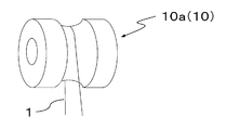
- the roller guide 10a shown in FIG. 1 guides the fiber 1 at the U-shaped groove portion while rotating.
- the oiling nozzle 10 b shown in FIG. 2 is used for attaching oil to the fiber 1.
- the rod guide 10c shown in FIG. 3 is used to converge or separate the fibers 1.
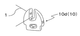
- the traverse guide 10d shown in FIG. 4 is used for guidance when winding the fiber 1 around the outer periphery of a cylindrical package.
- the friction disk 10e shown in FIG. 5 is used when the fiber 1 is twisted.
- FIG. 6 is a top view of the oiling nozzle 10b shown in FIG. 2 (viewed toward the white arrow in FIG. 2).
- the fiber guide is described with the reference numeral “10”, except when a specific fiber guide is described.
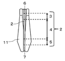
- the fiber guide 10 of the present disclosure includes a base body 11 and a yarn contact surface 2 that contacts the fiber 1 at least at a part on the base body 11, as shown in FIG.
- the yarn contact surface 2 is a surface that contacts the fiber 1 in the fiber guide 10, but in order to distinguish from the base body 11, the yarn contact surface extends to a depth of 0.2 mm from the surface that contacts the fiber 1. 2.
- the yarn contact surface 2 is colored for identification.
- the yarn contact surface 2 is limited to one in which the fiber 1 sending side and the sending side can be clearly distinguished, but the yarn contacting surface 2 is composed of a feeding portion 3, an intermediate portion 4 and a sending portion 5.
- the fiber guide having the yarn contact surface 2 composed of the feeding portion 3, the intermediate portion 4, and the feeding portion 5 is, for example, an oiling nozzle 10b shown in FIG.
- the yarn contact surface 2 of such an oiling nozzle 10 b has a pair of first end 6 and second end 7 in the traveling direction of the fiber 1.
- the first end 6 is a portion where the fiber 1 first comes into contact with the yarn contact surface 2 on the fiber 1 feeding side
- the second end 7 is the yarn contact surface 2 on the fiber 1 delivery side. This is the part where the fiber 1 is in contact with the end.
- the feeding portion 3 refers to a portion from the first end 6 to a portion corresponding to 1/5 of the total length when the first end 6 to the second end 7 on the yarn contact surface 2 are defined as the total length.
- the sending unit 5 refers to the portion from the second end 7 to a portion corresponding to 1/5 of the entire length.
- An area between the feeding portion 3 and the feeding portion 5 on the yarn contact surface 2 is an intermediate portion 4.
- the yarn contact surface 2 of the fiber guide 10 of the present disclosure is made of an aluminum oxide ceramic, and has a zirconium silicate phase 8 between the aluminum oxide crystals 9 as shown in FIG.
- the aluminum oxide ceramic is one in which aluminum oxide occupies 80% by mass or more out of 100% by mass of all components constituting the aluminum oxide ceramic.
- the yarn contact surface 2 is measured using an X-ray diffractometer (XRD), and identification is performed using a JCPDS card from the obtained 2 ⁇ (2 ⁇ is a diffraction angle) value.
- XRD X-ray diffractometer
- quantitative analysis of the components contained in the yarn contact surface 2 is performed using a fluorescent X-ray analyzer (XRF).
- XRF fluorescent X-ray analyzer
- the presence of aluminum oxide is confirmed by the identification of the XRD, and if the content converted from aluminum (Al) content measured by the XRF to aluminum oxide (Al 2 O 3 ) is 80% by mass or more, Aluminum oxide ceramics.
- the zirconium silicate phase 8 has a lower coefficient of friction than the aluminum oxide crystal 9.
- the zirconium silicate phase 8 is located between the aluminum oxide crystals 9, and thus the friction coefficient of the yarn contact surface 2 is low.
- the presence or absence of the zirconium silicate phase 8 on the yarn contact surface 2 may be confirmed by the following method.
- element mapping is performed at a location visually recognized as a phase existing between the aluminum oxide crystals 9. Then, if zirconium, silicon, and oxygen are simultaneously detected by element mapping, it is assumed that the fiber guide 10 of the present disclosure has the zirconium silicate phase 8. In addition, since the aluminum oxide layer 9 exists below the zirconium silicate phase 8, aluminum may be detected even when aluminum oxide is not included between the aluminum oxide crystals 9. .
- EPMA electron beam microanalyzer
- FIG. 7 schematically shows a state where the yarn contact surface 2 is observed with a scanning electron microscope (SEM) or the like.
- SEM scanning electron microscope
- the color tone relationship of FIG. 7 is based on an SEM image (photograph), and the zirconium silicate phase 8 exhibits a white color tone, and the aluminum oxide crystal 9 exhibits a black color tone.
- the zirconium silicate phase 8 and the aluminum oxide crystal 9 can be distinguished.
- the base 11 and the yarn contact surface 2 are made of an integral aluminum oxide ceramic, and the area ratio occupied by the zirconium silicate phase 8 on the yarn contact surface 2 is determined by the silicic acid inside the substrate 11. It may be larger than the area ratio occupied by the zirconium phase 8.
- the inside of the base 11 is a portion deeper than the surface of the base 11 by 0.2 mm or more.
- what is necessary is just to confirm the material of the base
- the thermal conductivity of the zirconium silicate phase 8 is about 3 to 8 W / m ⁇ K.
- the thermal conductivity of the aluminum oxide crystal 9 is about 15 to 40 W / m ⁇ K. Therefore, if the above-described configuration is satisfied, the yarn contact surface 2 in which the area ratio occupied by the zirconium silicate phase 8 is larger than that of the base body 11 has a lower thermal conductivity than the inside of the base body 11, and therefore guides the fiber 1. At this time, the frictional heat generated on the yarn contact surface 2 diffuses into the inside of the base body 11 having the higher thermal conductivity, and the temperature rise of the yarn contact surface 2 is suppressed.
- the area ratio occupied by the zirconium silicate phase 8 on the yarn contact surface 2 may be 0.2 area% or more larger than the area ratio occupied by the zirconium silicate phase 8 inside the base body 11. . And if such a structure is satisfied, even if the fiber 1 is guided for a long time, the fiber guide 10 of the present disclosure can maintain the friction coefficient of the yarn contact surface 2 more.
- the area ratio occupied by the zirconium silicate phase 8 on the yarn contact surface 2 may be, for example, 0.2 area% or more and 1.8 area% or less.
- the area ratio occupied by the zirconium silicate phase 8 in the inside of the substrate 11 is, for example, 0.1 area% or less, and the zirconium silicate phase 8 does not exist, that is, 0 area%.
- the area ratio occupied by the zirconium silicate phase 8 inside the yarn contact surface 2 and the substrate 11 may be calculated by the following method.
- a backscattered electron image (BEI) photograph (hereinafter simply referred to as a photograph) of the inside of the yarn contact surface 2 and the substrate 11 is taken using an SEM.
- the image analysis software “A image-kun” (registered trademark, manufactured by Asahi Kasei Engineering Corp., In the following, the image analysis software “A image-kun” refers to the image analysis software manufactured by Asahi Kasei Engineering Co., Ltd.).
- the area ratio occupied by the zirconium phase 8 can be determined.
- the area ratio occupied by the zirconium silicate phase 8 on the yarn contact surface 2 is an average value obtained by image analysis of six or more photographs of different portions of the yarn contact surface 2 taken at a magnification of 1000 to 3000 times. If the contact surface 2 is composed of the feeding section 3, the intermediate section 4 and the sending section 5, two photographs of different parts of the feeding section 3, the intermediate section 4 and the sending section 5 are subjected to image analysis.
- the average value may be an area ratio occupied by the zirconium silicate phase 8 on the yarn contact surface 2.
- the area ratio occupied by the zirconium silicate phase 8 inside the substrate 11 is an average value obtained by image analysis of six or more photographs of different portions inside the substrate 11 taken at a magnification of 1000 to 3000 times.
- the analysis conditions of “A image-kun” are, for example, that the crystal particle brightness is “bright”, the binarization method is “manual”, the shading is “present”, and the zirconium silicate phase 8 and the aluminum oxide crystal 9 A threshold value may be set so that can be clearly distinguished.
- the area ratio occupied by the zirconium silicate phase 8 in the feeding part 3 on the yarn contact surface 2 may be larger than the area ratio occupied by the zirconium silicate phase 8 in the intermediate part 4. If such a configuration is satisfied, the frictional resistance can be reduced in the feeding portion 3 where the fiber 1 is most susceptible to damage.
- the area ratio occupied by the zirconium silicate phase 8 in the feeding portion 3 in the yarn contact surface 2 may be 0.3 area% or more and 2.5 area% or less.
- the area ratio occupied by the zirconium silicate phase 8 in the feeding section 3 and the intermediate section 4 is image analysis in the same manner as the method for calculating the area ratio occupied by the zirconium silicate phase in the yarn contact surface 2 and the base 11 described above. What is necessary is just to calculate by the particle
- the area ratio occupied by the zirconium silicate phase 8 in the feeding section 3 is an average value obtained by image analysis of two or more photographs of different parts of the feeding section 3 taken at a magnification of 1000 to 3000 times.
- the area ratio occupied by the zirconium silicate phase 8 in the intermediate portion 4 is an average value obtained by image analysis of two or more photographs of different portions of the intermediate portion 4 taken at a magnification of 1000 to 3000 times.
- the average value of the equivalent circle diameter of the zirconium silicate phase 8 on the yarn contact surface 2 may be 0.6 ⁇ m or more and 3.2 ⁇ m or less.
- the equivalent circle diameter means the diameter of the circle when the circle is replaced with a circle equal to the area of the zirconium silicate phase 8. And if such a structure is satisfied, since the zirconium silicate phase 8 is not easily degranulated from the yarn contact surface 2, the friction coefficient of the yarn contact surface 2 can be further maintained.
- the average value of the equivalent circle diameter of the aluminum oxide crystal 9 is, for example, 10 ⁇ m or more and 25 ⁇ m or less.
- the average value of the equivalent circle diameters of the zirconium silicate phase 8 and the aluminum oxide crystal 9 can be calculated by the same method as the method for calculating the area ratio occupied by the zirconium silicate phase on the yarn contact surface 2 described above. it can.
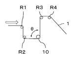
- the sliding test apparatus shown in FIG. 8 includes a roller R1, a roller R2, a fiber guide 10, a roller R3, and a roller R4, and is an apparatus that can guide the fiber 1 in this order.
- a tension detector (not shown) is connected to the roller R2 and the roller R3.
- the friction coefficient varies depending on the test conditions such as the type of the fiber 1, the shape of the fiber 1, the traveling speed of the fiber 1, the tension of the fiber 1, and ⁇ . For this reason, it is necessary to compare the friction coefficients under the same test conditions.
- the oiling nozzle 10b will be described as an example.
- the base body 11 and the yarn contact surface 2 are made of an integral aluminum oxide ceramic will be described as an example.
- zirconium silicate (ZrSiO 4 ) powder may be added when the slurry is produced.
- granules are produced by spray drying using a spray dryer.
- the granule, thermoplastic resin, wax and the like are put into a kneader and kneaded while heating to obtain a clay.
- the pellet used as the raw material for injection molding is obtained by throwing the obtained clay into a pelletizer.
- the obtained pellets are put into an injection molding machine (injection molding machine) and injection molded to obtain an oiling nozzle shaped molded body.
- injection molding machine injection molding machine
- a molding die capable of obtaining an oiling nozzle shape can be produced based on a general injection molding method, and this can be placed in an injection molding machine and injection molded. .
- the obtained compact is fired at a maximum temperature of 1500 ° C. or higher and 1600 ° C. or lower in an air atmosphere, and a holding time at the maximum temperature of 2 hours or longer and 5 hours or shorter, thereby obtaining a sintered body.
- firing conditions such as the maximum temperature and holding time vary depending on the shape and size of the product, and may be adjusted as necessary.
- the sintered body, polishing media and water are put into a wet barrel polishing machine to perform barrel polishing.
- the zirconium silicate powder by mixing the zirconium silicate powder with water, when the media collides with the sintered body in barrel polishing, the zirconium silicate powder enters between the aluminum oxide crystals 9, and the surface of the sintered body is silicic acid.
- the zirconium phase 8 is fixed.
- the sintered body is washed and dried to obtain the oiling nozzle 10b of the present disclosure.
- the area ratio occupied by the zirconium silicate phase 8 in the yarn contact surface 2 and the base 11 is the amount of the zirconium silicate powder added when preparing the slurry, the amount of the zirconium silicate powder mixed with water in barrel polishing, By adjusting the barrel polishing time, it can be controlled to an arbitrary value.
- the area ratio occupied by the zirconium silicate phase 8 in the feeding portion 3 and the intermediate portion 4 of the yarn contact surface 2 adjusts the amount of zirconium silicate powder mixed in water and barrel polishing time in barrel polishing and By masking a part of the feeding part 3 and the intermediate part 4 of the surface 2 and barrel polishing, it can be controlled to an arbitrary value.
- the average particle diameter of the zirconium silicate powder to be used may be adjusted.
- Oiling nozzles with different presence or absence of zirconium silicate phase on the yarn contact surface were prepared. Then, sliding tests were performed on these oiling nozzles, and the friction coefficients of the contact surfaces were compared.
- aluminum oxide powder, titanium oxide (TiO 2 ) powder and magnesium carbonate (MgCO 3 ) powder as a sintering aid were prepared. Each powder was weighed and mixed so that the aluminum oxide powder was 98.4% by mass, the titanium oxide powder was 1% by mass, and the magnesium carbonate powder was 0.6% by mass in terms of magnesium oxide (MgO). Then, the slurry was produced by putting into a mill with water and balls as the solvent and pulverizing.
- thermoplastic resin and wax were added to the granules, and the mixture was put into a kneader and kneaded while heating to obtain a clay. Then, the obtained kneaded material was put into a pelletizer to obtain pellets as a raw material for injection molding. Next, the obtained pellets were put into an injection molding machine and injection molded to obtain an oiling nozzle-shaped molded body.
- the compact was fired at a maximum temperature of 1550 ° C. in an air atmosphere and a holding time at the maximum temperature of 3 hours to obtain a sintered body.
- this sintered body, polishing media and water were put into a wet barrel polishing machine, and barrel polishing was performed for 2 hours.
- barrel polishing zirconium silicate powder having an average particle size of 3.5 ⁇ m was mixed with water so that the addition amount was 0.015% by mass with respect to 100% by mass in total of water and zirconium silicate powder. .
- the sintered body was washed and dried, so that the sample No. 1 was obtained.
- barrel polishing was performed using water not mixed with zirconium silicate powder. 2 was obtained.
- oiling nozzles having different area ratios occupied by the zirconium silicate phase in the yarn contact surface and the inside of the substrate were produced. Then, sliding tests were performed on these oiling nozzles, and the friction coefficients of the contact surfaces were compared.
- the amount of zirconium silicate powder shown in Table 2 was added when the slurry was produced, and the amount of zirconium silicate powder mixed with water in barrel polishing was changed to the amount shown in Table 2.
- the sample No. 1 is the same as the sample No. 1 in Example 1
- Sample No. 5 is the same sample as Sample No. 1 in Example 1.
- the addition amount of the aluminum oxide powder was reduced by the addition amount of the added zirconium silicate powder.
- the area ratio occupied by the zirconium silicate phase in the yarn contact surface of each sample and inside the substrate was calculated by the following method.
- the area ratio occupied by the phase was determined. Specifically, the area ratio occupied by the zirconium silicate phase on the contact surface is an image analysis of two photographs taken at different magnifications of the feed portion, the intermediate portion, and the feed portion of the contact surface taken at a magnification of 2000 times. It was set as the average value. On the other hand, the area ratio occupied by the zirconium silicate phase in the inside of the substrate was an average value obtained by analyzing six images of different parts taken inside at a magnification of 2000 times.
- Example 2 the same sliding test as in Example 1 was performed except that the measurement start time of the friction coefficient was 20 minutes after the start of the sliding test, and the friction coefficient of the contact surface of each sample was obtained. The results are shown in Table 2.
- sample N was as low as 0.36 or less. From this, if the area ratio occupied by the zirconium silicate phase on the contact surface is 0.2 area% or more larger than the area ratio occupied by the zirconium silicate phase inside the substrate, the friction coefficient of the contact surface can be more maintained. I understood.
- oiling nozzles having different area ratios occupied by the zirconium silicate phase at the feeding portion and the middle portion of the contact surface were prepared. Then, sliding tests were performed on these oiling nozzles, and the friction coefficients of the contact surfaces were compared.
- the amount of zirconium silicate phase mixed is adjusted by adjusting the amount of zirconium silicate powder mixed with water, and by masking part of the feeding part and intermediate part of the yarn contact surface, the area ratio occupied by the zirconium silicate phase
- the sample No. 9 is the same as the sample No. 1 in Example 1 except that the value shown in Table 3 is the same as that of Sample No. 1 in Example 1. .
- sample N was found that when the area ratio of the zirconium silicate phase in the feeding portion is 0.3 area% or more and 2.5 area% or less, the friction coefficient of the yarn contact surface can be further reduced.
- oiling nozzles having different average circle equivalent diameters of the zirconium silicate phase on the yarn contact surface were produced. Then, sliding tests were performed on these oiling nozzles, and the friction coefficients of the contact surfaces were compared.
- the zirconium silicate powder having the average particle diameter shown in Table 4 was used, and the barrel time shown in Table 4 was used, and the production method was the same as the production method of Sample No. 6 in Example 2.
- Sample No. 20 is the same sample as Sample No. 6 of Example 2.
- the reason for changing the barrel time in each sample is that the area ratio occupied by the zirconium silicate phase on the yarn contact surface of each sample is 0.6 area%.
- the average value of the equivalent circle diameter of the zirconium silicate phase on the contact surface of each sample was calculated by the same method as the method of calculating the area ratio occupied by the zirconium silicate phase on the contact surface of Example 2.
Landscapes
- Engineering & Computer Science (AREA)
- Mechanical Engineering (AREA)
- Textile Engineering (AREA)
- Guides For Winding Or Rewinding, Or Guides For Filamentary Materials (AREA)
- Spinning Methods And Devices For Manufacturing Artificial Fibers (AREA)
- Inorganic Fibers (AREA)
- Compositions Of Oxide Ceramics (AREA)
Abstract
本開示の繊維ガイドは、基体と、該基体上の少なくとも一部に繊維に接触する接糸面とを備える。そして、この接糸面は、酸化アルミニウム質セラミックスからなり、酸化アルミニウム結晶同士の間に珪酸ジルコニウム相を有する。
Description
本開示は、繊維ガイドに関する。
繊維の案内においては、ローラーガイド、オイリングノズル、ロッドガイド、トラバースガイドおよびフリクションディスクと呼ばれる様々な形状の繊維ガイドが繊維機械に取り付けられ使用されている。そして、繊維と接触する繊維ガイドの表面(以下、接糸面と記載する。)には、繊維に傷やほつれ等のダメージを発生させにくいことが求められている。さらに、繊維ガイドには、安価に製造できることも求められている。
このことから、繊維ガイドを構成する材料としては、安価でありながら、耐磨耗性に優れた酸化アルミニウム質セラミックスが用いられることが多い。
例えば、特許文献1には、ビッカース硬さHVが1900以上であり、酸化アルミニウムからなるガイドが開示されている。
本開示の繊維ガイドは、基体と、該基体上の少なくとも一部に繊維に接触する接糸面とを備える。そして、この接糸面は、酸化アルミニウム質セラミックスからなり、酸化アルミニウム結晶同士の間に珪酸ジルコニウム相を有する。
近年、繊維の生産効率の向上のために、繊維の送り速度が1000~10000m/分と極めて高速化してきている。よって、繊維の送り速度の高速化によっても、繊維にダメージを与えることの少ない、接糸面の摩擦係数が低い繊維ガイドが求められている。
本開示の繊維ガイドは、接糸面の摩擦係数が低いことから、繊維を案内した際に、繊維にダメージが発生することを低減できる。以下に、本開示の繊維ガイドについて、図面を参照しながら詳細に説明する。
最初に、繊維ガイドの代表的な種類について、図1~図5を参照しながら説明する。まず、図1に示すローラーガイド10aは、回転しながらU字溝部分で繊維1を案内するものである。次に、図2に示すオイリングノズル10bは、繊維1にオイルを付着させるのに使用されるものである。次に、図3に示すロッドガイド10cは、繊維1を収束したり分離したりするのに使用されるものである。次に、図4に示すトラバースガイド10dは、円筒状のパッケージの外周に繊維1を巻き取るときの案内に使用されるものである。また、図5に示すフリクションディスク10eは、繊維1に撚りをかける際に使用されるものである。
なお、図6は、図2に示すオイリングノズル10bの上面図(図2における白抜き矢印に向かって見た図)である。なお、以降の記載においては、特定の繊維ガイドについて記載する場合を除き、繊維ガイドには「10」の符号を付して説明する。
本開示の繊維ガイド10は、図6に示すように、基体11と、基体11上の少なくとも一部に繊維1に接触する接糸面2を備える。ここで、接糸面2とは、繊維ガイド10において繊維1に接触する表面のことであるが、基体11との識別上、繊維1に接触する表面から0.2mmの深さまでを接糸面2とする。なお、図6においては、識別のため接糸面2を着色して示している。そして、接糸面2において、繊維1の送入側と送出側とが明確に区別できるものに限られるが、接糸面2は、送入部3、中間部4および送出部5からなる。ここで、送入部3、中間部4および送出部5からなる接糸面2を有する繊維ガイドとは、例えば、図2に示すオイリングノズル10bである。このようなオイリングノズル10bの接糸面2は、繊維1の進行方向に一対の第1端6および第2端7を有する。ここで、第1端6とは、繊維1の送入側において接糸面2に繊維1が最初に接する部分であり、第2端7とは、繊維1の送出側において接糸面2に繊維1が最後まで接していた部分である。そして、送入部3とは、接糸面2における第1端6から第2端7までを全長としたとき、第1端6から全長の1/5にあたる部分までのことを指す。一方、送出部5とは、第2端7から全長の1/5にあたる部分までのことを指す。また、接糸面2において送入部3と送出部5との間の領域が中間部4である。
そして、本開示の繊維ガイド10における接糸面2は、酸化アルミニウム質セラミックスからなり、図7に示すように、酸化アルミニウム結晶9同士の間に珪酸ジルコニウム相8を有する。
ここで、酸化アルミニウム質セラミックスとは、酸化アルミニウム質セラミックスを構成する全成分100質量%のうち、酸化アルミニウムが80質量%以上占めるものである。
接糸面2の材質は、以下の方法で確認すればよい。まず、X線回折装置(XRD)を用いて、接糸面2を測定し、得られた2θ(2θは、回折角度である。)の値よりJCPDSカードを用いて同定を行なう。次に、蛍光X線分析装置(XRF)を用いて、接糸面2の含有成分の定量分析を行なう。そして、上記XRDの同定により酸化アルミニウムの存在が確認され、上記XRFで測定したアルミニウム(Al)の含有量から酸化アルミニウム(Al2O3)に換算した含有量が80質量%以上であれば、酸化アルミニウム質セラミックスである。
珪酸ジルコニウム相8は、酸化アルミニウム結晶9に比べて、摩擦係数が低い。本開示の繊維ガイド10は、酸化アルミニウム結晶9同士の間に珪酸ジルコニウム相8が位置しているため、接糸面2の摩擦係数が低い。
ここで、接糸面2における珪酸ジルコニウム相8の有無は、以下の方法で確認すればよい。
まず、電子線マイクロアナライザー(EPMA)を用いて、酸化アルミニウム結晶9同士の間に存在する相として視認される箇所における元素マッピングを行なう。そして、元素マッピングにより、ジルコニウム、珪素および酸素が同時に検出されれば、本開示の繊維ガイド10が、珪酸ジルコニウム相8を有するとする。なお、珪酸ジルコニウム相8の下方には、酸化アルミニウム層9が存在するものであることから、酸化アルミニウム結晶9同士の間に酸化アルミニウムを含んでいない場合であってもアルミニウムを検出する場合がある。
また、図7は、接糸面2を走査型電子顕微鏡(SEM)等において観察した状態を模式的に示したものである。ここで、図7の色調関係はSEM画像(写真)に基づくものであり、珪酸ジルコニウム相8は白色系の色調を呈し、酸化アルミニウム結晶9は黒色系の色調を呈するものであることから、目視において珪酸ジルコニウム相8と酸化アルミニウム結晶9とは識別できるものである。
また、本開示の繊維ガイド10は、基体11および接糸面2が一体物の酸化アルミニウム質セラミックスからなるとともに、接糸面2における珪酸ジルコニウム相8が占める面積比率は、基体11の内部における珪酸ジルコニウム相8が占める面積比率よりも大きくてもよい。ここで、基体11の内部とは、基体11の表面から0.2mm以上深い部分のことである。なお、基体11の材質は、上述した接糸面2の材質を確認した方法と同じ方法で確認すればよい。
珪酸ジルコニウム相8の熱伝導率は、3~8W/m・K程度である。一方、酸化アルミニウム結晶9の熱伝導率は、15~40W/m・K程度である。よって、上述した構成を満足するならば、珪酸ジルコニウム相8が占める面積比率が基体11よりも大きい接糸面2は、基体11の内部よりも熱伝導率が低いことから、繊維1を案内する際に接糸面2で発生する摩擦熱が、熱伝導率のより高い方である基体11の内部に拡散していき、接糸面2の温度上昇が抑制される。これにより、本開示の繊維ガイド10は、繊維1を長時間案内しても、繊維1に傷やほつれ等のダメージを発生させにくい。言い換えるならば、接糸面2の摩擦係数を維持できる。
さらに、本開示の繊維ガイド10は、接糸面2における珪酸ジルコニウム相8が占める面積比率は、基体11の内部における珪酸ジルコニウム相8が占める面積比率よりも0.2面積%以上大きくてもよい。そして、このような構成を満足するならば、繊維1を長時間案内しても、本開示の繊維ガイド10は、接糸面2の摩擦係数をより維持できる。
ここで、接糸面2における珪酸ジルコニウム相8が占める面積比率は、例えば、0.2面積%以上1.8面積%以下であってもよい。一方、基体11の内部における珪酸ジルコニウム相8が占める面積比率は、例えば、0.1面積%以下であり、珪酸ジルコニウム相8が存在しない、つまり0面積%であってもよい。
そして、接糸面2および基体11の内部における珪酸ジルコニウム相8が占める面積比率は、以下の方法で算出すればよい。まず、接糸面2および基体11の内部の反射電子像(BEI)写真(以下、単に写真と記載する)を、SEMを用いて撮影する。そして、上述したように、珪酸ジルコニウム相8は白色系の色調を呈するものであることから、この写真を用いて、画像解析ソフト「A像くん」(登録商標、旭化成エンジニアリング(株)製、なお、以降に画像解析ソフト「A像くん」と記した場合、旭化成エンジニアリング(株)製の画像解析ソフトを示すものとする。)の粒子解析という手法を適用して画像解析を行なうことにより、珪酸ジルコニウム相8が占める面積比率を求めることができる。
ここで、接糸面2における珪酸ジルコニウム相8が占める面積比率は、倍率1000~3000倍で撮影した、接糸面2の異なる箇所の写真を6枚以上画像解析した平均値とする。なお、接触面2が、送入部3、中間部4および送出部5からなるならば、送入部3、中間部4および送出部5のそれぞれ異なる箇所の写真を2枚ずつ画像解析し、その平均値を接糸面2における珪酸ジルコニウム相8が占める面積比率とすればよい。
一方、基体11の内部における珪酸ジルコニウム相8が占める面積比率は、倍率1000~3000倍で撮影した、基体11の内部の異なる箇所の写真を6枚以上画像解析した平均値とする。
なお、「A像くん」の解析条件としては、例えば、結晶粒子の明度を「明」、2値化の方法を「手動」、シェーディングを「有」として、珪酸ジルコニウム相8と酸化アルミニウム結晶9とを明確に区別できるように閾値を設定すればよい。
また、本開示の繊維ガイド10は、接糸面2において、送入部3における珪酸ジルコニウム相8が占める面積比率が、中間部4における珪酸ジルコニウム相8が占める面積比率よりも大きくてもよい。このような構成を満足するならば、繊維1が最もダメージを受けやすい箇所である送入部3において、摩擦抵抗を小さくすることができる。ここで、本開示の繊維ガイド10は、接糸面2のうち送入部3における珪酸ジルコニウム相8が占める面積比率が、0.3面積%以上2.5面積%以下であってもよい。
なお、送入部3および中間部4における珪酸ジルコニウム相8が占める面積比率は、上述した接糸面2および基体11の内部における珪酸ジルコニウム相が占める面積比率を算出した方法と同様に、画像解析ソフト「A像くん」の粒子解析により算出すればよい。具体的には、送入部3における珪酸ジルコニウム相8が占める面積比率は、倍率1000~3000倍で撮影した、送入部3の異なる箇所の写真を2枚以上画像解析した平均値とする。また、中間部4における珪酸ジルコニウム相8が占める面積比率は、倍率1000~3000倍で撮影した、中間部4の異なる箇所の写真を2枚以上画像解析した平均値とする。
また、本開示の繊維ガイド10は、接糸面2における珪酸ジルコニウム相8の円相当径の平均値が、0.6μm以上3.2μm以下であってもよい。ここで、円相当径とは、珪酸ジルコニウム相8の面積と等しい円に置き換えた場合における、円の直径を意味している。そして、このような構成を満足するならば、接糸面2から珪酸ジルコニウム相8が脱粒しくいことから、接糸面2の摩擦係数をより維持できる。
なお、酸化アルミニウム結晶9の円相当径の平均値は、例えば、10μm以上25μm以下である。
ここで、珪酸ジルコニウム相8および酸化アルミニウム結晶9のそれぞれの円相当径の平均値は、上述した接糸面2における珪酸ジルコニウム相が占める面積比率を算出した方法と同様の方法で算出することができる。
次に、接糸面2の摩擦係数の測定方法について、図8を用いて説明する。図8に示す摺動試験装置は、ローラーR1、ローラーR2、繊維ガイド10、ローラーR3およびローラーR4を備え、この順に繊維1を案内することができる装置である。ここで、ローラーR2およびローラーR3には、テンション検出器(図示していない)が接続されている。
そして、この摺動試験装置を用いて繊維1を案内し、ローラーR2のテンション検出器によって検出されたテンションT1の測定値と、ローラーR3のテンション検出器によって検出されたテンションT2の測定値とを用いて、アモントンの法則の式(μ={ln(T2-T1)}/θ)で計算することにより摩擦係数(μ)を求めることができる。
なお、摩擦係数は、繊維1の種類、繊維1の形状、繊維1の走行速度、繊維1の張力、θ等の試験条件によって変化する。このため、摩擦係数の比較にあたっては、同じ試験条件で行なう必要がある。
次に、本開示の繊維ガイド10の製造方法の一例について説明する。ここでは、繊維ガイド10のうち、オイリングノズル10bを例に挙げて説明する。また、基体11および接糸面2が一体物の酸化アルミニウム質セラミックスからなる場合を例に挙げて説明する。
まず、酸化アルミニウム(Al2O3)粉末、焼結助剤および溶媒をボールとともにミルに入れて、所定の粒度となるまで粉砕し、スラリーを作製する。ここで、基体11の内部に珪酸ジルコニウム相8を有する繊維ガイド10を得るには、スラリーを作製する際に珪酸ジルコニウム(ZrSiO4)粉末を添加すればよい。
次に、得られたスリラーにバインダを添加した後、スプレードライヤーを用いて、噴霧乾燥を行なうことで顆粒を作製する。
次に、この顆粒と熱可塑性樹脂とワックス等とをニーダに投入して加熱しながら混練し、坏土を得る。そして、得られた坏土をペレタイザーに投入することにより、インジェクション成形(射出成形)用の原料となるペレットを得る。次に、得られたペレットをインジェクション成形機(射出成形機)に投入して射出成形することにより、オイリングノズル形状の成形体を得る。なお、オイリングノズル形状の成形体を得るためには、一般的な射出成形法に基づいて、オイリングノズル形状が得られる成形型を作製し、これをインジェクション成形機に設置して射出成形すればよい。
次に、得られた成形体を、大気雰囲気中で最高温度を1500℃以上1600℃以下とし、この最高温度での保持時間を2時間以上5時間以下として焼成することで、焼結体を得る。なお、最高温度および保持時間等の焼成条件は、製品の形状および大きさにより変化するため、必要に応じて調整すればよい。
次に、焼結体、研磨用メディアおよび水を湿式バレル研磨機に入れ、バレル研磨を行なう。このとき、珪酸ジルコニウム粉末を水に混ぜておくことで、バレル研磨において焼結体にメディアが衝突した際に、珪酸ジルコニウム粉末が酸化アルミニウム結晶9同士の間に入り込み、焼結体の表面に珪酸ジルコニウム相8として固着する。
バレル研磨後、焼結体を洗浄、乾燥させることで、本開示のオイリングノズル10bを得る。
また、接糸面2および基体11の内部における珪酸ジルコニウム相8が占める面積比率は、スラリーを作製する際に添加する珪酸ジルコニウム粉末の量と、バレル研磨において水に混ぜる珪酸ジルコニウム粉末の量と、バレル研磨の時間とを調整することで、任意の値に制御することができる。
また、接糸面2の送入部3および中間部4における珪酸ジルコニウム相8が占める面積比率は、バレル研磨において水に混ぜる珪酸ジルコニウム粉末の量とバレル研磨の時間とを調整するとともに、接糸面2の送入部3および中間部4の一部をマスクしてバレル研磨することで、任意の値に制御することができる。
また、接糸面2における珪酸ジルコニウム相8の円相当径の平均値を、0.6μm以上3.2μm以下とするには、使用する珪酸ジルコニウム粉末の平均粒子径を調整すればよい。
接糸面における珪酸ジルコニウム相の有無を異ならせたオイリングノズルを作製した。そして、これらのオイリングノズルにおいて摺動試験を行ない、接糸面の摩擦係数の比較を行なった。
まず、酸化アルミニウム粉末、焼結助剤としての酸化チタン(TiO2)粉末および炭酸マグネシウム(MgCO3)粉末を準備した。そして、各粉末を、酸化アルミニウム粉末が98.4質量%、酸化チタン粉末が1質量%、炭酸マグネシウム粉末が酸化マグネシウム(MgO)換算で0.6質量%となるように秤量し混合した。その後、溶媒である水とボールとともにミルに入れて粉砕することで、スラリーを作製した。
次に、このスリラーにバインダを添加した後、スプレードライヤーを用いて、噴霧乾燥を行なうことで顆粒を作製した。
次に、この顆粒に熱可塑性樹脂とワックスとを加え、ニーダに投入して加熱しながら混練し、坏土を得た。そして、得られた坏土をペレタイザーに投入し、インジェクション成形用の原料となるペレットを得た。次に、得られたペレットをインジェクション成形機に投入して射出成形することにより、オイリングノズル形状の成形体を得た。
次に、この成形体を、大気雰囲気中で最高温度を1550℃とし、この最高温度での保持時間を3時間として焼成を行ない、焼結体を得た。
次に、この焼結体、研磨用メディアおよび水を湿式バレル研磨機に入れ、バレル研磨を2時間行なった。このとき、バレル研磨において、平均粒子径が3.5μmの珪酸ジルコニウム粉末を、水および珪酸ジルコニウム粉末の合計100質量%に対して、0.015質量%の添加量となるように水に混ぜた。
その後、焼結体を洗浄、乾燥させることで、試料No.1を得た。
また、上記製造方法において、珪酸ジルコニウム粉末を混ぜていない水を用いてバレル研磨を行ない、試料No.2を得た。
次に、図8に示す摺動試験装置に各試料をセットし、摺動試験を行なうことで、各試料の摩擦係数を求めた。なお、測定条件は、以下の通りとした。
繊維の種類:ナイロン(75デニール)
繊維の走行速度:1500m/分
θ:90°
繊維の張力:50gf
測定頻度:10回(1分毎)
摩擦係数:検出されたテンションからそれぞれの摩擦係数を求め、10回の平均値を摩擦係数とした。
繊維の種類:ナイロン(75デニール)
繊維の走行速度:1500m/分
θ:90°
繊維の張力:50gf
測定頻度:10回(1分毎)
摩擦係数:検出されたテンションからそれぞれの摩擦係数を求め、10回の平均値を摩擦係数とした。
結果を表1に示す。

表1に示す結果から、試料No.2に比べて、試料No.1は、摩擦係数が0.36と低いものであった。このことから、接糸面において、珪酸ジルコニウム相を有すれば、接糸面の摩擦係数を低くできることが分かった。
次に、接糸面および基体の内部における珪酸ジルコニウム相が占める面積比率が異なるオイリングノズルを作製した。そして、これらのオイリングノズルにおいて摺動試験を行ない、接糸面の摩擦係数の比較を行なった。
作製方法としては、スラリーを作製する際に表2に示す量の珪酸ジルコニウム粉末を添加するとともに、バレル研磨において、水に混合する珪酸ジルコニウム粉末の添加量を表2に示す量としたこと以外は、実施例1の試料No.1の作製方法と同様であり、試料No.5は、実施例1の試料No.1と同じ試料である。なお、スラリーに珪酸ジルコニウム粉末を添加する際には、添加した珪酸ジルコニウム粉末の添加量だけ、酸化アルミニウム粉末の添加量を減らした。
次に、各試料の接糸面および基体の内部における珪酸ジルコニウム相が占める面積比率を、以下の方法で算出した。まず、接糸面および基体の内部の反射電子像写真を、SEMを用いて撮影した。そして、珪酸ジルコニウム相は白色系の色調を呈するものであることから、この写真を用いて、画像解析ソフト「A像くん」の粒子解析という手法を適用して画像解析を行なうことにより、珪酸ジルコニウム相が占める面積比率を求めた。具体的には、接糸面における珪酸ジルコニウム相が占める面積比率は、倍率2000倍で撮影した、接糸面の送入部、中間部および送出部のそれぞれ異なる箇所の写真を2枚ずつ画像解析した平均値とした。一方、基体の内部における珪酸ジルコニウム相が占める面積比率は、倍率2000倍で撮影した内部の異なる箇所の写真を6枚画像解析した平均値とした。
また、摩擦係数の測定開始時刻を、摺動試験を開始してから20分後にしたこと以外は実施例1と同様の摺動試験を行ない、各試料の接糸面の摩擦係数を求めた。結果を表2に示す。

表2に示す結果から、試料No.3に比べて、試料No.4~8は、接糸面の摩擦係数が0.38以下と低いものであった。このことから、接糸面における珪酸ジルコニウム相が占める面積比率が、基体の内部における珪酸ジルコニウム相が占める面積比率よりも大きければ、接糸面の摩擦係数を維持できることが分かった。
また、試料Nо.4~8の中でも試料No.5~8は、接糸面の摩擦係数が0.36以下と低いものであった。このことから、接糸面における珪酸ジルコニウム相が占める面積比率が、基体の内部における珪酸ジルコニウム相が占める面積比率よりも0.2面積%以上大きければ、接糸面の摩擦係数をより維持できることが分かった。
次に、接糸面の送入部および中間部における珪酸ジルコニウム相が占める面積比率が異なるオイリングノズルを作製した。そして、これらのオイリングノズルにおいて摺動試験を行ない、接糸面の摩擦係数の比較を行なった。
作製方法としては、バレル研磨において、水に混合する珪酸ジルコニウム粉末の添加量を調整するとともに、接糸面の送入部および中間部の一部をマスクすることで、珪酸ジルコニウム相が占める面積比率が表3に示す値となるようにしたこと以外は、実施例1の試料No.1の作製方法と同様であり、試料No.9は、実施例1の試料No.1と同じ試料である。
次に、実施例1と同様の摺動試験を行ない、各試料の接糸面の摩擦係数を求めた。結果を表3に示す。
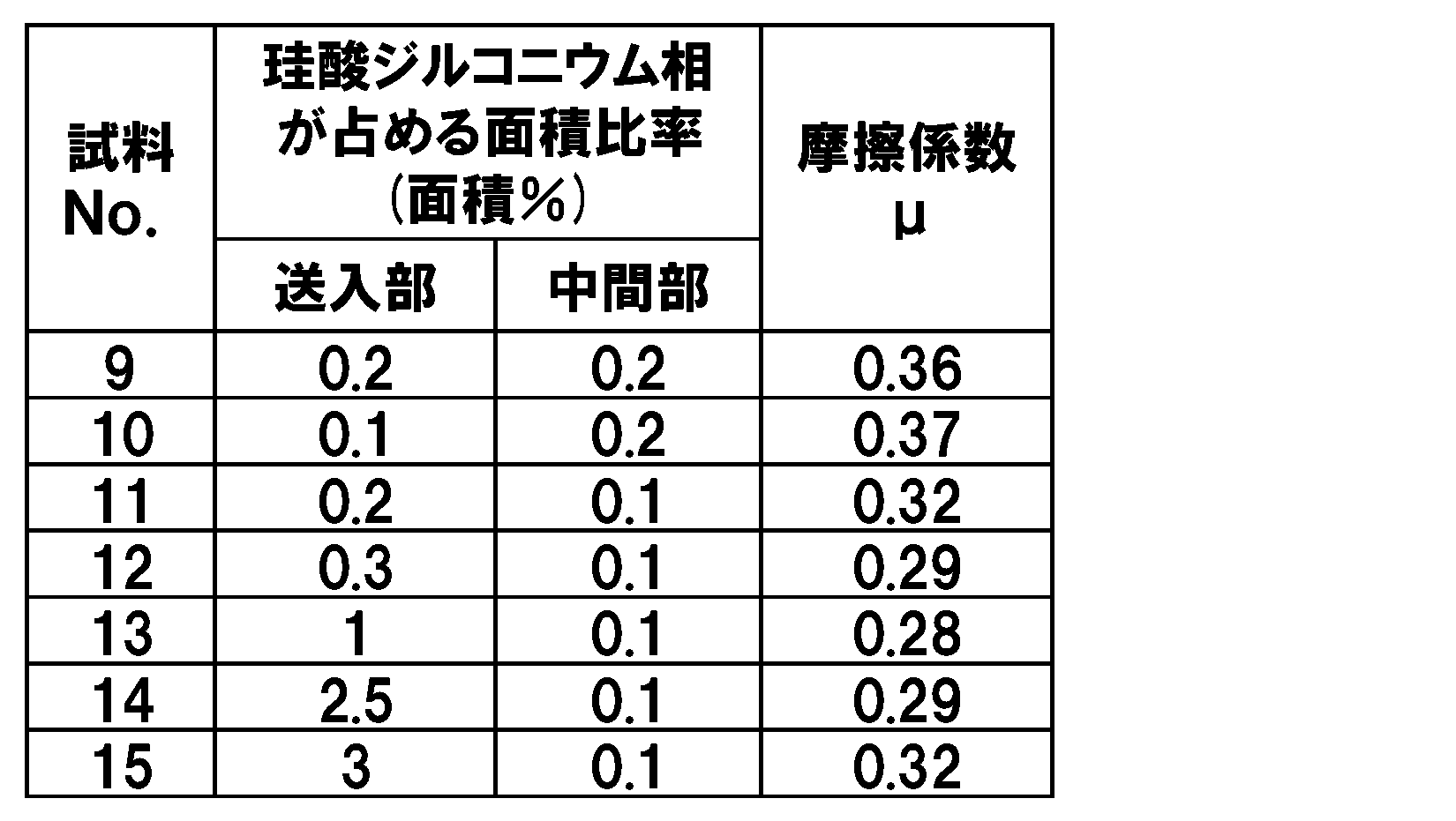
表3に示す結果から、試料No.9、10に比べて、試料No.11~15は、接糸面の摩擦係数が0.32以下と低いものであった。このことから、送入部における珪酸ジルコニウム相が占める面積比率が、中間部における珪酸ジルコニウム相が占める面積比率よりも大きいことにより、接糸面の摩擦係数をより低くできることが分かった。
また、試料Nо.11~15の中でも試料No.12~14は、接糸面の摩擦係数が0.29以下と低いものであった。このことから、送入部における珪酸ジルコニウム相が占める面積比率が0.3面積%以上2.5面積%以下であれば、接糸面の摩擦係数をさらに低くできることが分かった。
次に、接糸面における珪酸ジルコニウム相の円相当径の平均値が異なるオイリングノズルを作製した。そして、これらのオイリングノズルにおいて摺動試験を行ない、接糸面の摩擦係数の比較を行なった。
作製方法としては、バレル研磨において、表4に示す平均粒子径の珪酸ジルコニウム粉末を使用するとともに、表4に示すバレル時間にしたこと以外は、実施例2の試料No.6の作製方法と同様であり、試料No.20は、実施例2の試料No.6と同じ試料である。なお、各試料においてバレル時間を変化させるのは、各試料の接糸面における珪酸ジルコニウム相が占める面積比率を0.6面積%とするためである。
次に、各試料の接糸面における珪酸ジルコニウム相の円相当径の平均値を、実施例2の接糸面における珪酸ジルコニウム相が占める面積比率を算出した方法と同様の方法で算出した。
また、実施例2と同様の摺動試験を行ない、各試料の接糸面の摩擦係数を求めた。結果を表4に示す。

表4に示す結果から、試料No.16、20に比べて、試料No.17~19は、接糸面の摩擦係数が0.29以下と低いものであった。このことから、接糸面における珪酸ジルコニウム相の円相当径の平均値が、0.6μm以上3.2μm以下であるならば、接糸面の摩擦係数をより維持できることが分かった。
1:繊維
2:接糸面
3:送入部
4:中間部
5:送出部
6:第1端
7:第2端
8:珪酸ジルコニウム相
9:酸化アルミニウム結晶
10a:ローラーガイド
10b:オイリングノズル
10c:ロッドガイド
10d:トラバースガイド
10e:フリクションディスク
10:繊維ガイド
11:基体
R1~R4:ローラー
2:接糸面
3:送入部
4:中間部
5:送出部
6:第1端
7:第2端
8:珪酸ジルコニウム相
9:酸化アルミニウム結晶
10a:ローラーガイド
10b:オイリングノズル
10c:ロッドガイド
10d:トラバースガイド
10e:フリクションディスク
10:繊維ガイド
11:基体
R1~R4:ローラー
Claims (6)
- 基体と、該基体上の少なくとも一部に繊維に接触する接糸面とを備え、
該接糸面は、酸化アルミニウム質セラミックスからなり、酸化アルミニウム結晶同士の間に珪酸ジルコニウム相を有する繊維ガイド。 - 前記基体および前記接糸面が一体物の酸化アルミニウム質セラミックスからなり、
前記接糸面における前記珪酸ジルコニウム相が占める面積比率は、前記基体の内部における前記珪酸ジルコニウム相が占める面積比率よりも大きい請求項1に記載の繊維ガイド。 - 前記接糸面における前記珪酸ジルコニウム相が占める面積比率は、前記基体の内部における前記珪酸ジルコニウム相が占める面積比率よりも0.2面積%以上大きい請求項2に記載の繊維ガイド。
- 前記接糸面は送入部、中間部および送出部からなり、前記送入部における前記珪酸ジルコニウム相が占める面積比率は、前記中間部における前記珪酸ジルコニウム相が占める面積比率よりも大きい請求項1乃至請求項3のいずれかに記載の繊維ガイド。
- 前記送入部における前記珪酸ジルコニウム相が占める面積比率は0.3面積%以上2.5面積%以下である請求項4に記載の繊維ガイド。
- 前記接糸面における前記珪酸ジルコニウム相の円相当径の平均値は、0.6μm以上3.2μm以下である請求項1乃至請求項5のいずれかに記載の繊維ガイド。
Priority Applications (3)
| Application Number | Priority Date | Filing Date | Title |
|---|---|---|---|
| JP2019509784A JP6789379B2 (ja) | 2017-03-29 | 2018-03-26 | 繊維ガイド |
| EP18777287.6A EP3604635A4 (en) | 2017-03-29 | 2018-03-26 | FIBER GUIDE |
| CN201880021566.9A CN110520558B (zh) | 2017-03-29 | 2018-03-26 | 纤维引导器 |
Applications Claiming Priority (2)
| Application Number | Priority Date | Filing Date | Title |
|---|---|---|---|
| JP2017-065419 | 2017-03-29 | ||
| JP2017065419 | 2017-03-29 |
Publications (1)
| Publication Number | Publication Date |
|---|---|
| WO2018181148A1 true WO2018181148A1 (ja) | 2018-10-04 |
Family
ID=63677519
Family Applications (1)
| Application Number | Title | Priority Date | Filing Date |
|---|---|---|---|
| PCT/JP2018/012082 Ceased WO2018181148A1 (ja) | 2017-03-29 | 2018-03-26 | 繊維ガイド |
Country Status (4)
| Country | Link |
|---|---|
| EP (1) | EP3604635A4 (ja) |
| JP (1) | JP6789379B2 (ja) |
| CN (1) | CN110520558B (ja) |
| WO (1) | WO2018181148A1 (ja) |
Families Citing this family (1)
| Publication number | Priority date | Publication date | Assignee | Title |
|---|---|---|---|---|
| EP4177200B1 (de) | 2021-11-04 | 2026-03-18 | Saurer Intelligent Technology AG | Garnreiniger für eine arbeitsstelle einer textilmaschine mit einem fadenführungselement |
Citations (5)
| Publication number | Priority date | Publication date | Assignee | Title |
|---|---|---|---|---|
| JPH11286824A (ja) * | 1998-03-31 | 1999-10-19 | Toray Ind Inc | 繊維用油剤付与ガイド装置および油剤付与方法 |
| JP2001158658A (ja) * | 1999-11-29 | 2001-06-12 | Kyocera Corp | 繊維用ガイド部材 |
| JP2003213522A (ja) | 2002-01-15 | 2003-07-30 | Toray Ind Inc | ポリエステル繊維の製造方法 |
| WO2012176777A1 (ja) * | 2011-06-20 | 2012-12-27 | 京セラ株式会社 | 繊維ガイド |
| WO2016136819A1 (ja) * | 2015-02-25 | 2016-09-01 | 京セラ株式会社 | 繊維ガイド |
Family Cites Families (18)
| Publication number | Priority date | Publication date | Assignee | Title |
|---|---|---|---|---|
| JPS59138571A (ja) * | 1983-01-29 | 1984-08-09 | Kyocera Corp | 糸道 |
| CA1287245C (en) * | 1985-12-20 | 1991-08-06 | Union Carbide Corporation | Wear-resistant laser-engraved metallic carbide surfaces for friction rolls for working elongate members, methods for producing same andmethods for working elongate members |
| CZ282501B6 (cs) * | 1988-10-07 | 1997-07-16 | Iro Ab | Zařízení na ukládání a podávání niti pro textilní stroje |
| JPH06108303A (ja) * | 1992-07-01 | 1994-04-19 | Takao Seisakusho:Kk | 分繊用櫛形ガイド |
| KR100212934B1 (ko) * | 1993-06-07 | 1999-08-02 | 무라세 사치코 | 합사기 |
| JPH09328255A (ja) * | 1996-06-10 | 1997-12-22 | Sadaichi Murase | 糸巻機 |
| JPH10102330A (ja) * | 1996-09-30 | 1998-04-21 | Kyocera Corp | スレッドガイド及びその製造方法 |
| JPH10102315A (ja) * | 1996-09-30 | 1998-04-21 | Kyocera Corp | オイリングノズル |
| JP3667108B2 (ja) * | 1998-08-31 | 2005-07-06 | 京セラ株式会社 | 糸状体のガイドローラ |
| JP2003129349A (ja) * | 2001-10-18 | 2003-05-08 | Murata Mach Ltd | 糸条加工ノズル |
| CN1347853A (zh) * | 2001-11-23 | 2002-05-08 | 王国梁 | 透明氧化铝陶瓷导丝器及其制造方法 |
| CN1211314C (zh) * | 2002-10-11 | 2005-07-20 | 上海施迈尔精密陶瓷有限公司 | 氧化锆增韧氧化铝陶瓷纺织瓷件的制造方法 |
| CN202913179U (zh) * | 2012-11-19 | 2013-05-01 | 宝得粉末注射成形(常熟)有限公司 | 一种编织横机用纱嘴 |
| CN202967726U (zh) * | 2012-12-14 | 2013-06-05 | 福建省长乐市添利织物有限公司 | 一种加弹机导丝装置 |
| CN103628249B (zh) * | 2013-10-29 | 2016-05-18 | 陆粉干 | 纺织用低摩擦阻力线钩 |
| WO2015093531A1 (ja) * | 2013-12-17 | 2015-06-25 | 京セラ株式会社 | 繊維ガイド |
| CN203976092U (zh) * | 2014-05-05 | 2014-12-03 | 浙江宏泰锆业科技有限公司 | 一种用于纺织机械中便于织线高速运行的陶瓷嵌片 |
| WO2017038699A1 (ja) * | 2015-08-28 | 2017-03-09 | 京セラ株式会社 | 繊維ガイド |
-
2018
- 2018-03-26 CN CN201880021566.9A patent/CN110520558B/zh active Active
- 2018-03-26 WO PCT/JP2018/012082 patent/WO2018181148A1/ja not_active Ceased
- 2018-03-26 JP JP2019509784A patent/JP6789379B2/ja active Active
- 2018-03-26 EP EP18777287.6A patent/EP3604635A4/en not_active Withdrawn
Patent Citations (5)
| Publication number | Priority date | Publication date | Assignee | Title |
|---|---|---|---|---|
| JPH11286824A (ja) * | 1998-03-31 | 1999-10-19 | Toray Ind Inc | 繊維用油剤付与ガイド装置および油剤付与方法 |
| JP2001158658A (ja) * | 1999-11-29 | 2001-06-12 | Kyocera Corp | 繊維用ガイド部材 |
| JP2003213522A (ja) | 2002-01-15 | 2003-07-30 | Toray Ind Inc | ポリエステル繊維の製造方法 |
| WO2012176777A1 (ja) * | 2011-06-20 | 2012-12-27 | 京セラ株式会社 | 繊維ガイド |
| WO2016136819A1 (ja) * | 2015-02-25 | 2016-09-01 | 京セラ株式会社 | 繊維ガイド |
Non-Patent Citations (1)
| Title |
|---|
| See also references of EP3604635A4 |
Also Published As
| Publication number | Publication date |
|---|---|
| EP3604635A1 (en) | 2020-02-05 |
| CN110520558A (zh) | 2019-11-29 |
| CN110520558B (zh) | 2022-02-25 |
| JP6789379B2 (ja) | 2020-11-25 |
| EP3604635A4 (en) | 2020-12-30 |
| JPWO2018181148A1 (ja) | 2020-02-27 |
Similar Documents
| Publication | Publication Date | Title |
|---|---|---|
| CN202809036U (zh) | 纤维引导器 | |
| US20100234207A1 (en) | Abrasion-resistant sintered body, sliding member, and pump | |
| JP6290927B2 (ja) | 繊維ガイド | |
| JP6789379B2 (ja) | 繊維ガイド | |
| WO2018003800A1 (ja) | 繊維ガイド | |
| JP6190086B2 (ja) | 繊維ガイド | |
| JP2017179620A (ja) | 繊維ガイド | |
| WO2016136819A1 (ja) | 繊維ガイド | |
| JP6041719B2 (ja) | ジルコニア質焼結体からなる熱処理用部材 | |
| JP6426881B1 (ja) | 釣糸用ガイド部材およびこれを備える釣竿 | |
| JP2761746B2 (ja) | 糸 道 | |
| JP2001122667A (ja) | 窒化珪素質焼結部材、セラミックボール、ボールベアリング及びセラミック摺動部品 | |
| JP2902823B2 (ja) | 糸ガイドおよびその製造方法 | |
| JP6280004B2 (ja) | 釣り糸用ガイド部材 | |
| JP2008007881A (ja) | 給油用ローラ及びこれを用いた紡糸引取り装置 | |
| JP2019052405A (ja) | 仮撚機用ディスク |
Legal Events
| Date | Code | Title | Description |
|---|---|---|---|
| 121 | Ep: the epo has been informed by wipo that ep was designated in this application |
Ref document number: 18777287 Country of ref document: EP Kind code of ref document: A1 |
|
| ENP | Entry into the national phase |
Ref document number: 2019509784 Country of ref document: JP Kind code of ref document: A |
|
| NENP | Non-entry into the national phase |
Ref country code: DE |
|
| ENP | Entry into the national phase |
Ref document number: 2018777287 Country of ref document: EP Effective date: 20191029 |