WO2018182017A1 - Dispositif générateur d'ondes ultrasonores - Google Patents
Dispositif générateur d'ondes ultrasonores Download PDFInfo
- Publication number
- WO2018182017A1 WO2018182017A1 PCT/JP2018/013978 JP2018013978W WO2018182017A1 WO 2018182017 A1 WO2018182017 A1 WO 2018182017A1 JP 2018013978 W JP2018013978 W JP 2018013978W WO 2018182017 A1 WO2018182017 A1 WO 2018182017A1
- Authority
- WO
- WIPO (PCT)
- Prior art keywords
- ultrasonic
- irradiation
- ultrasonic irradiation
- unit
- body surface
- Prior art date
- Legal status (The legal status is an assumption and is not a legal conclusion. Google has not performed a legal analysis and makes no representation as to the accuracy of the status listed.)
- Ceased
Links
Images

Classifications
-
- A—HUMAN NECESSITIES
- A61—MEDICAL OR VETERINARY SCIENCE; HYGIENE
- A61B—DIAGNOSIS; SURGERY; IDENTIFICATION
- A61B90/00—Instruments, implements or accessories specially adapted for surgery or diagnosis and not covered by any of the groups A61B1/00 - A61B50/00, e.g. for luxation treatment or for protecting wound edges
- A61B90/36—Image-producing devices or illumination devices not otherwise provided for
- A61B90/361—Image-producing devices, e.g. surgical cameras
-
- A—HUMAN NECESSITIES
- A61—MEDICAL OR VETERINARY SCIENCE; HYGIENE
- A61B—DIAGNOSIS; SURGERY; IDENTIFICATION
- A61B5/00—Measuring for diagnostic purposes; Identification of persons
- A61B5/0033—Features or image-related aspects of imaging apparatus, e.g. for MRI, optical tomography or impedance tomography apparatus; Arrangements of imaging apparatus in a room
- A61B5/0036—Features or image-related aspects of imaging apparatus, e.g. for MRI, optical tomography or impedance tomography apparatus; Arrangements of imaging apparatus in a room including treatment, e.g., using an implantable medical device, ablating, ventilating
-
- A—HUMAN NECESSITIES
- A61—MEDICAL OR VETERINARY SCIENCE; HYGIENE
- A61B—DIAGNOSIS; SURGERY; IDENTIFICATION
- A61B5/00—Measuring for diagnostic purposes; Identification of persons
- A61B5/0059—Measuring for diagnostic purposes; Identification of persons using light, e.g. diagnosis by transillumination, diascopy, fluorescence
- A61B5/0077—Devices for viewing the surface of the body, e.g. camera, magnifying lens
-
- A—HUMAN NECESSITIES
- A61—MEDICAL OR VETERINARY SCIENCE; HYGIENE
- A61B—DIAGNOSIS; SURGERY; IDENTIFICATION
- A61B5/00—Measuring for diagnostic purposes; Identification of persons
- A61B5/44—Detecting, measuring or recording for evaluating the integumentary system, e.g. skin, hair or nails
- A61B5/441—Skin evaluation, e.g. for skin disorder diagnosis
- A61B5/445—Evaluating skin irritation or skin trauma, e.g. rash, eczema, wound, bed sore
-
- A—HUMAN NECESSITIES
- A61—MEDICAL OR VETERINARY SCIENCE; HYGIENE
- A61B—DIAGNOSIS; SURGERY; IDENTIFICATION
- A61B5/00—Measuring for diagnostic purposes; Identification of persons
- A61B5/72—Signal processing specially adapted for physiological signals or for diagnostic purposes
- A61B5/7271—Specific aspects of physiological measurement analysis
- A61B5/7275—Determining trends in physiological measurement data; Predicting development of a medical condition based on physiological measurements, e.g. determining a risk factor
-
- A—HUMAN NECESSITIES
- A61—MEDICAL OR VETERINARY SCIENCE; HYGIENE
- A61B—DIAGNOSIS; SURGERY; IDENTIFICATION
- A61B90/00—Instruments, implements or accessories specially adapted for surgery or diagnosis and not covered by any of the groups A61B1/00 - A61B50/00, e.g. for luxation treatment or for protecting wound edges
- A61B90/39—Markers, e.g. radio-opaque or breast lesions markers
-
- A—HUMAN NECESSITIES
- A61—MEDICAL OR VETERINARY SCIENCE; HYGIENE
- A61N—ELECTROTHERAPY; MAGNETOTHERAPY; RADIATION THERAPY; ULTRASOUND THERAPY
- A61N7/00—Ultrasound therapy
-
- A—HUMAN NECESSITIES
- A61—MEDICAL OR VETERINARY SCIENCE; HYGIENE
- A61N—ELECTROTHERAPY; MAGNETOTHERAPY; RADIATION THERAPY; ULTRASOUND THERAPY
- A61N7/00—Ultrasound therapy
- A61N7/02—Localised ultrasound hyperthermia
-
- A—HUMAN NECESSITIES
- A61—MEDICAL OR VETERINARY SCIENCE; HYGIENE
- A61B—DIAGNOSIS; SURGERY; IDENTIFICATION
- A61B90/00—Instruments, implements or accessories specially adapted for surgery or diagnosis and not covered by any of the groups A61B1/00 - A61B50/00, e.g. for luxation treatment or for protecting wound edges
- A61B90/39—Markers, e.g. radio-opaque or breast lesions markers
- A61B2090/3937—Visible markers
- A61B2090/395—Visible markers with marking agent for marking skin or other tissue
-
- A—HUMAN NECESSITIES
- A61—MEDICAL OR VETERINARY SCIENCE; HYGIENE
- A61N—ELECTROTHERAPY; MAGNETOTHERAPY; RADIATION THERAPY; ULTRASOUND THERAPY
- A61N7/00—Ultrasound therapy
- A61N2007/0004—Applications of ultrasound therapy
-
- A—HUMAN NECESSITIES
- A61—MEDICAL OR VETERINARY SCIENCE; HYGIENE
- A61N—ELECTROTHERAPY; MAGNETOTHERAPY; RADIATION THERAPY; ULTRASOUND THERAPY
- A61N7/00—Ultrasound therapy
- A61N2007/0004—Applications of ultrasound therapy
- A61N2007/0034—Skin treatment
Definitions
- the present invention relates to an ultrasonic irradiation apparatus that cauterizes a pain site by irradiating ultrasonic waves from outside the body.
- the affected area is irradiated with high-density focused ultrasound (HIFU) from outside the body by using an ultrasonic irradiation device.
- HIFU high-density focused ultrasound
- Bone pain alleviation treatment is performed in which a site is cauterized non-invasively (see Patent Documents 1 and 2).
- the ultrasonic irradiation apparatus of the present disclosure includes an ultrasonic transducer that irradiates focused ultrasonic waves from the outside toward the body surface, and an optical imaging unit that images the body surface of the ultrasonic irradiation target site.
- FIG. 1 is a schematic configuration diagram of the ultrasonic irradiation apparatus according to the first embodiment.
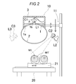
- FIG. 2 is a schematic configuration diagram of the ultrasonic irradiation apparatus according to the second embodiment.
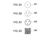
- 3A to 3D are front views showing examples of irradiation position guides used in the embodiment.
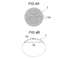
- FIG. 4A is a front view of the ultrasonic irradiation unit of the ultrasonic irradiation apparatus according to the embodiment as viewed from below
- FIG. 4B is a side view of the ultrasonic irradiation unit as viewed from the side.
- ultrasonic irradiation devices used for bone pain relief treatment can be classified into two types.
- (1) MRgHIFU by diagnosing and guiding the ultrasonic irradiation target site such as an affected part to be treated.
- the therapeutic transducers that cauterize the pain site are the same HIFU type.
- the HIFU transducer has various shapes, for example, the outer shape is circular or quadrangular, and each bulges in a concave surface in the direction opposite to the ultrasonic irradiation direction, or is not bulged and has a plate shape, etc. There is.
- the above-mentioned MRgHIFU and USgHIFU specify a site causing pain by using images obtained from the MRI guide device and the ultrasonic guide device, respectively, and a therapeutic transducer is placed on the specified site.
- the affected area is irradiated with HIFU to cauterize the affected area.
- the general MRI guide device and ultrasonic guide device currently used for diagnosis can detect and image an organ or the like, which is a soft tissue in the back of the body, which causes pain occurring in the deep part.
- an organ or the like which is a soft tissue in the back of the body, which causes pain occurring in the deep part.
- the location of the affected area of bone pain that occurs near the body surface with a depth of several millimeters to 20 mm is specified by the doctor searching for the tender point by manual palpation, and the tender point is applied to the skin on the body surface. This is done by marking with a pen. Then, depending on the mark or mark, a medical person such as a doctor manually positions the treatment transducer for irradiating the HIFU. Therefore, there is no part for confirming whether or not the therapeutic transducer is disposed at an appropriate irradiation position.
- the aforementioned MRI guide device and ultrasonic guide device can be used to determine the degree of burn after ultrasonic irradiation when skin burns, burns, etc. due to ultrasonic irradiation and ultrasonic cauterization occur.
- ultrasonic irradiation imaging and measurement cannot be performed simultaneously. Therefore, the conventional ultrasonic irradiation apparatus did not have a part for monitoring the skin state during ultrasonic irradiation in real time.
- the present disclosure has been made in view of such circumstances, and provides an ultrasonic irradiation apparatus that can guide a treatment transducer to an appropriate irradiation position and can observe the state of the body surface during ultrasonic irradiation.
- the purpose is to do.
- the ultrasonic irradiation apparatus includes an ultrasonic transducer that irradiates focused ultrasonic waves from the outside toward the body surface, and an optical imaging unit that images the body surface of the ultrasonic irradiation target site.
- Ultrasound irradiation for bone pain relief treatment used to relieve bone pain derived from cancer, joint pain, etc., that is, pain occurring in a shallow part of the body with a depth of several to 30 mm from the body surface Device. As shown in FIG.
- this ultrasonic irradiation apparatus includes a power supply unit, a cooling water generation unit (not shown), a personal computer, in addition to a HIFU irradiation unit 10 and a treatment support base 20 each having one or a plurality of ultrasonic transmission elements. And the like.
- the moving bed 21 of the treatment support table 20 and the support unit 11 of the HIFU irradiation unit 10 are configured to move a patient's body lying on the bed for ultrasonic irradiation treatment in two planes, the XY axis direction and the height axis.
- the position in the Z-axis direction can be freely adjusted so that the ultrasonic irradiation target part, in this example, the thighs of both legs can be held at an appropriate position directly below the HIFU irradiation unit 10.
- the HIFU irradiation unit 10 can rotate around the axis of the support unit 11 and irradiate ultrasonic waves obliquely with respect to the vertical direction.
- the movable bed 21 may be provided with a restraining belt or the like for maintaining the posture / position of the patient.
- the movement / holding mechanism of the patient's body that is the ultrasonic irradiation target site is not limited to the configuration of the above example, and any known device that can hold the ultrasonic irradiation target site in an appropriate position is known. You may employ
- the ultrasonic transducer includes an ultrasonic irradiation unit having a surface facing the irradiation target, and the ultrasonic irradiation unit has an opening on the surface facing the irradiation target.
- the optical imaging unit is arranged to be able to image the body surface of the ultrasonic irradiation target site through the opening.
- the HIFU irradiation unit 10 shown in FIG. 1 includes an ultrasonic transducer 1 that is a disk-shaped ultrasonic irradiation unit that spreads over an affected area, and cooling for cooling a patient's body that is an ultrasonic irradiation target site. It is mainly composed of a resin film balloon 2 for holding water, and a housing 3 that is an irradiation unit case that is supported by the support unit 11 and is suspended on the patient's body. .
- connection between each member, such as piping and wiring in each figure, is abbreviate
- the disk-shaped ultrasonic transducer 1 is formed in a disk shape or a disk shape that spreads over the affected part as a whole, and the affected part side, which is the lower surface, is recessed downward in the vertical direction. It has a parabolic shape that curves in a straight line.
- a large number of ultrasonic wave transmitting elements 1a as shown in FIG. 4A are arranged on the concave inner surface. Since the inner surface of the ultrasonic transducer 1 is formed as a curved surface having a radius of curvature that converges toward a single point, when these ultrasonic transmission elements 1a oscillate simultaneously, they are oscillated as shown in FIG. The ultrasonic waves are focused on the focal point and become a high-density HIFU.
- an opening and a through-hole 1b to which a lens of a camera C1, which is a first optical imaging element to be described later, can be attached are provided in the center of the disk-like and parabolic shape. Then, based on the detection information and position information of the marker M1 that is the irradiation position guide under the balloon 2 by the camera C1 attached to the through hole 1b, a control unit such as a computer (not shown) converts the ultrasonic transducer 1 The HIFU irradiation unit 10 including the balloon 2 is controlled to be lowered and placed at an appropriate position directly above the marker M1.
- the ultrasonic transducer 1 has a disk shape or the like that spreads over the affected area as in the above example, and the ultrasonic transmission is performed by arranging as many ultrasonic oscillators as possible on a wide surface facing the affected area. This is to ensure strength. Therefore, the shape of the ultrasonic irradiation part is not limited to the above-described disk shape or disk shape, and the overall shape of the irradiation part is particularly limited as long as a wide surface facing the affected part can be secured. It is not a thing.
- the outer shape may be a circle or a quadrangle, and the outer shape may swell on the concave surface in the direction opposite to the ultrasonic irradiation direction, or may be a plate shape that does not swell.
- the ultrasonic oscillator is a phased array type HIFU capable of changing the focal point of the ultrasonic wave and the depth of field
- the parabolic curvature radius of the ultrasonic transducer 1 can be changed, or the bottom surface can be changed. It is also possible to adopt a flat plate-shaped irradiation part.
- the balloon 2 is configured by using a transparent or translucent film made of resin, and degassed cold water produced by a cooling water generating unit (not shown), in this case, cold water having a water temperature of about 18 ° C. is connected to the cooling water generating unit.
- the temperature of the water in the balloon 2 is maintained at a constant temperature so that the body surface in contact with the bottom and the bottom of the balloon 2 can be cooled.
- the reason for cooling the skin surface of the ultrasonic irradiation target site is to reduce burns and burns on the body surface and the surface layer due to ultrasonic irradiation, and the circulating cold water suppresses the generation of bubbles due to ultrasonic irradiation.
- the “transparent or translucent” of the balloon 2 in the present embodiment means that the resin film used has a light transmittance of 80% or more in the visible wavelength band and the ultraviolet wavelength band. .
- the camera C1 is attached to the through hole 1b provided at the center of the disk-shaped ultrasonic transducer 1, and the cooling water in the balloon 2 and the resin film under the balloon 2 are attached.
- the body surface of the ultrasonic irradiation target site directly below the balloon 2 can be imaged.
- an optical filter F and a light L1 are attached to the inside of the balloon 2 below the front end of the lens side of the camera C1, and the ultrasonic irradiation target site where the marker M1 is located is more A clear image can be taken.
- a seal member such as an O-ring is provided between the optical filter F and the light L1 at the tip of the camera C1 and the surrounding through-hole 1b so as to make the gap a watertight structure.
- the above-mentioned degassed cooling water is prevented from leaking.
- Other structures may be adopted as the water leakage preventing structure of the through hole 1b.
- the therapeutic HIFU irradiation unit 10 is appropriately irradiated by analyzing and using the image of the body surface of the ultrasonic irradiation target portion obtained from the camera C1. It is possible to easily guide to the position, and it is possible to monitor the state of the body surface of the ultrasonic irradiation target site in real time during the ultrasonic irradiation.
- the ultrasonic irradiation apparatus of the present embodiment by analyzing and using the image of the body surface of the ultrasonic irradiation target site obtained from the optical imaging unit, the therapeutic transducer is placed at an appropriate irradiation position.
- the state of the skin on the body surface of the ultrasonic irradiation target site can be monitored in real time during the ultrasonic irradiation.
- the ultrasonic irradiation apparatus of this invention can reduce the burden of the patient at the time of ultrasonic irradiation.
- the ultrasonic irradiation apparatus is an ultrasonic irradiation target hidden directly under an ultrasonic irradiation unit such as a substantially disk shape or a substantially disk shape that spreads over the affected area without moving the HIFU transducer for treatment.
- the region can be imaged during ultrasonic irradiation. Therefore, it is possible to reduce the burden on the patient such as shortening of the treatment time.
- the irradiation target site during ultrasonic irradiation can be imaged because the bottom of the balloon 2 and the inside deaerated water are transparent.
- it is translucent and the camera C1 is disposed at a position where the position of the marker M1, which is an ultrasonic irradiation target portion located in a place hidden behind the ultrasonic irradiation section, can be seen from inside the balloon 2. is there.
- the camera C1 has the optical filter F and the light L1, it can take various imaging forms.
- the ultrasonic irradiation apparatus includes an image processing unit that performs arithmetic processing on an image obtained from the optical imaging unit, and the image processing unit includes a plurality of ultrasonic irradiation target portions of the obtained image.
- a skin state determination unit that determines the skin state of the ultrasonic irradiation target site based on the distribution of reflected light of the light in the specific wavelength band.
- the standard is a tungsten lamp with a color temperature of 2856.6K that emits “standard light” as the light L1.
- an Illuminant A light source or a standard Illuminant D 65 light source that is daylight with a color correlation temperature of 6504K
- the position of the marker M1 that can be seen through the balloon 2 is imaged with the camera C1 by about 400 to 700 nm.
- a reflected light image in the visible light band is obtained.
- the spectrum of the ultrasonic irradiation target site can be obtained by spectrally separating the obtained image in 10 nm steps using an image processing unit (not shown). From this spectral spectrum, L * value, a * value, and b * value, which are color parameters based on the CIELAB (L * a * b * ) color space, can be obtained by calculation.
- the state of the skin of the ultrasonic irradiation target site can be monitored in real time.
- this is an example of a skin condition determination unit, and the a * value can also be used to determine the risk of occurrence of skin burns at the ultrasonic irradiation target site.
- the range of the 256 gradation a * scale in the above-described L * a * b * color space is from the maximum green saturation (a 0 ) to the maximum red saturation (a 255 ) . It is represented by the value 128-255.
- b * scale ranging from 256 gradations is from maximum blue saturated (b 0) to a maximum yellow saturated (b 255), yellowness is represented by 128 to 255 in the b * value.
- the image processing unit is configured to apply the ultrasonic irradiation target on the basis of the distribution of reflected light of a plurality of specific wavelength bands in the ultrasonic irradiation target portion of the obtained image. It includes a burn occurrence risk determination unit for determining the risk of occurrence of skin burns at the site.
- the state of the skin at the ultrasonic irradiation target site and the risk of burns may be determined.
- a skin condition determination unit or a burn occurrence risk determination unit are all examples of a skin condition determination unit or a burn occurrence risk determination unit.
- a laser LED, an ultraviolet (UV) LED, or the like that emits excitation light of a specific wavelength is used as a light source such as the light L1.
- the image of the position of the marker M1 is captured by the camera C1 using the diodes and lamps, and the fluorescence image and the fluorescence spectrum of the target region can be acquired.
- a laser LED when used as a light source to irradiate light having a wavelength of about 405 nm and a fluorescent image including reflected light in a visible light band of about 450 to 700 nm is acquired, blood circulation failure due to a burn is caused by hemoglobin. It is considered that a phenomenon occurs in which the light intensity of fluorescence of about 500 to 550 nm is lowered. Thereby, the burn degree of the skin of the target region can be determined.
- collagen in the skin also fluoresces, for example, when UV-LED is used to irradiate light with a wavelength of about 325 nm and a fluorescent image in a visible light band of about 400 to 410 nm is acquired, skin damage due to burns is caused. When this occurs, a phenomenon that the light intensity of fluorescence of about 400 and 405 nm derived from collagen is reduced occurs. This also makes it possible to determine the degree of skin burn in the target area.
- the skin condition determination unit or the burn occurrence risk determination unit in the present embodiment are also examples of the skin condition determination unit or the burn occurrence risk determination unit in the present embodiment.
- the ultrasonic irradiation apparatus of the present invention analyzes and uses the image of the body surface of the ultrasonic irradiation target portion obtained from the camera C1, and thereby the body surface of the target portion is analyzed.
- the state can be monitored in real time without moving the HIFU irradiation unit 10.
- the control part of the ultrasonic irradiation apparatus of this embodiment when the skin state and the risk of burn occurrence, for example, a * value, etc. obtained by the above methods exceed a preset threshold value.
- a burn generation prevention unit that stops the ultrasonic oscillation of the ultrasonic transducer 1 may be provided. That is, by making the above-described skin condition determination unit or burn occurrence risk determination unit interlock with the control unit that controls the ultrasonic transducer 1, it is possible to more reliably suppress the occurrence of burns, burns, and the like. It becomes possible.
- the ultrasonic irradiation apparatus of the present embodiment includes an irradiation position guide for the ultrasonic irradiation, the irradiation position guide is positioned and disposed on the body surface, and the irradiation position guide is detected by the optical imaging unit. And an ultrasonic irradiation position guide for controlling the position and irradiation angle of the ultrasonic transducer based on the position information of the irradiation position guide.
- the optical imaging unit referred to here may or may not be the same as the “optical imaging unit that images the body surface of the ultrasonic irradiation target part” described above, and its function is also “through the ultrasonic irradiation unit. It is not limited to those capable of imaging the body surface of the ultrasonic irradiation target site. Further, the arrangement position and the number can be arbitrarily set.
- the irradiation position guide is an index or a mark for guiding the HIFU irradiation unit 10 serving as a therapeutic transducer to a position suitable for irradiation.
- the position of the irradiation position guide is specified by a doctor or the like by manual palpation. This is done by finding tender points.
- the irradiation position guide is a film-like marker disposed on the body surface, or the irradiation position guide is made of ink printed on the body surface.
- a configuration that is a mark, stamp, or signature is preferably employed.
- printing on the body surface means not only printing with a printer such as a printer, but also handwriting using a pen or the like, stamping with a stamp, sticking a seal, etc. It is a concept that broadly encompasses the whole part to be marked.
- the number and position of the irradiation position guides including the markers are not particularly limited, and a plurality of irradiation position guides may be provided.
- the optical imaging unit for detecting the irradiation position guide and a part of the ultrasonic irradiation position guide unit are not limited to the camera C1 disposed in the disk-shaped ultrasonic transducer 1 described above, for example, As in the second camera C2, the third camera C3, and the like shown in FIG. 2, a plurality of irradiation position guides can be arranged at positions where observation and detection can be performed without limiting the arrangement positions.
- the ultrasonic irradiation apparatus shown in FIG. 2 includes illumination units L2, L3 and the like that illuminate the installation position of the irradiation position guide so that the irradiation position guide is easy to see.
- the light L1 and the illumination portions L2, L3, etc., that illuminate these irradiation position guides are so-called black lights that are UV lamps that can irradiate ultraviolet rays, and fluorescent ink is used as the ink used for the above-described marker or body surface printing If the ultraviolet reflective ink called is used, the irradiation position guide can be more clearly identified regardless of indoor lighting or the like.
- the film marker used as an irradiation position guide is a resin film or the like so that it adheres to the skin without interposing air between the body surface when pasted on the body surface using glue or adhesive. It is made of thin and soft material.
- the resin used is preferably a polymer material such as silicone that does not absorb or reflect ultrasonic waves and transmits ultrasonic waves.
- the appropriate thickness of the film is preferably 1 ⁇ 4 of the wavelength of the ultrasonic wave. When the frequency of the irradiation ultrasonic wave is 1 MHz, the thickness of the film is preferably about 370 ⁇ m.
- a transparent or translucent film having a light transmittance of 80% or more may be used so that the camera C1 can be seen through the skin under the film marker.
- the planar shape of the film marker when viewed from the medical personnel or the upper optical imaging unit side is, for example, a round shape or a polygonal shape having a diameter of about 5 to 30 mm as shown in FIGS. 3A to 3D. As shown in the figure, printing with ink or the like is carried out on the surface (front noodle).
- the color and pattern of printing are not particularly limited, but the marker M1 in which only one black dot is printed at the center as shown in FIG. 3A, and the central tenderness as shown in FIG. 3B.
- Marker M2 that surrounds three points from three sides at equal distances, equidistant from each other, marker M3 having a safety frame that is an irradiation limit line at a round edge as shown in FIG. 3C, and a patient as shown in FIG. 3D
- Various forms such as a marker M4 functioning as a two-dimensional code or a one-dimensional code can be used.
- stamps, signs, etc. made of ink printed on the body surface by doctors or the like as irradiation position guides
- marks such as those shown in FIGS. 3A to 3D on the skin using a seal or the like.
- stamps can be printed.
- a simple point, an O-shaped sign, or an X-shaped sign may be used.
- a plurality of these signs may be printed so as to surround the tender point, and the barycentric points may be used as a reference by image analysis.
- printing may be performed with invisible ink such as ultraviolet reflective ink.
- a marker, mark, stamp, sign, or the like may be provided at a location slightly away from the tender point, and the therapeutic HIFU irradiation unit 10 may be guided to the irradiation position on the basis of these.
- the ultrasonic irradiation apparatus is placed on the moving bed 21 of the treatment support 20 on the basis of the film marker, mark, stamp, sign, etc., which are the irradiation position guides on the body surface.
- the patient's body lying in the supine position is automatically moved to a position suitable for irradiation by moving the moving bed 21 and the HIFU irradiation unit 10 in the three-axis directions, and the upper part of the focal point that is the irradiation center of the HIFU irradiation unit 10 is moved. , Can be lowered to an appropriate position.
- the ultrasonic irradiation apparatus of this embodiment can reduce the irradiation time of ultrasonic cauterization and reduce the burden on the patient.
- the occurrence of skin burns due to ultrasonic cauterization can be prevented or suppressed by monitoring.
- a camera used for the optical imaging unit of the ultrasonic irradiation apparatus of the present embodiment for example, a CCD image sensor such as a charge coupled device or a CMOS image sensor such as a complementary metal oxide semiconductor, a lens, a memory, etc.
- a digital camera for photographing still images / moving images is used. This camera is appropriately provided with a cut-off filter, a band pass filter, and the like.
- each unit described in the above-described embodiment such as ultrasonic oscillation control, patient support / movement control, image processing, skin condition determination, burn risk determination, and burn prevention, is a control unit composed of a personal computer or the like. It is possible to configure software and applications that constitute the units, and these may be configured to operate in cooperation with each other.
- the configuration of the ultrasonic irradiation apparatus other than the HIFU irradiation unit 10 in the embodiment is not particularly limited, and the present invention can be widely applied to other than the ultrasonic irradiation apparatus having the HIFU irradiation unit.
Landscapes
- Health & Medical Sciences (AREA)
- Life Sciences & Earth Sciences (AREA)
- Engineering & Computer Science (AREA)
- General Health & Medical Sciences (AREA)
- Surgery (AREA)
- Veterinary Medicine (AREA)
- Public Health (AREA)
- Biomedical Technology (AREA)
- Animal Behavior & Ethology (AREA)
- Medical Informatics (AREA)
- Heart & Thoracic Surgery (AREA)
- Molecular Biology (AREA)
- Pathology (AREA)
- Physics & Mathematics (AREA)
- Biophysics (AREA)
- Nuclear Medicine, Radiotherapy & Molecular Imaging (AREA)
- Radiology & Medical Imaging (AREA)
- Dermatology (AREA)
- Oral & Maxillofacial Surgery (AREA)
- Artificial Intelligence (AREA)
- Computer Vision & Pattern Recognition (AREA)
- Physiology (AREA)
- Psychiatry (AREA)
- Signal Processing (AREA)
- Surgical Instruments (AREA)
- Ultra Sonic Daignosis Equipment (AREA)
Abstract
Cette invention concerne un dispositif générateur d'ultrasons comprenant : un transducteur à ultrasons qui émet des HIFU qui sont des ultrasons focalisés en direction de la surface d'un corps depuis l'extérieur ; et une unité d'imagerie optique ou une caméra qui capture une image de la surface du corps à un emplacement devant être exposé aux ultrasons. Un guide de position ou un repère est placé et agencé sur la surface du corps, le repère est détecté par la caméra, et la position et l'angle d'orientation du transducteur à ultrasons sont réglés en fonction des informations de position du repère. Par conséquent, il est possible de guider un transducteur à visée thérapeutique vers une position appropriée et de surveiller l'état de la surface d'un corps pendant qu'elle est exposée aux ultrasons.
Priority Applications (4)
| Application Number | Priority Date | Filing Date | Title |
|---|---|---|---|
| JP2019509430A JPWO2018182017A1 (ja) | 2017-03-30 | 2018-03-30 | 超音波照射装置 |
| CN201880022496.9A CN110494087A (zh) | 2017-03-30 | 2018-03-30 | 超声波照射装置 |
| US16/498,539 US20200037880A1 (en) | 2017-03-30 | 2018-03-30 | Ultrasonic irradiation device |
| EP18774356.2A EP3603532A4 (fr) | 2017-03-30 | 2018-03-30 | Dispositif générateur d'ondes ultrasonores |
Applications Claiming Priority (2)
| Application Number | Priority Date | Filing Date | Title |
|---|---|---|---|
| JP2017-069316 | 2017-03-30 | ||
| JP2017069316 | 2017-03-30 |
Publications (1)
| Publication Number | Publication Date |
|---|---|
| WO2018182017A1 true WO2018182017A1 (fr) | 2018-10-04 |
Family
ID=63676590
Family Applications (1)
| Application Number | Title | Priority Date | Filing Date |
|---|---|---|---|
| PCT/JP2018/013978 Ceased WO2018182017A1 (fr) | 2017-03-30 | 2018-03-30 | Dispositif générateur d'ondes ultrasonores |
Country Status (5)
| Country | Link |
|---|---|
| US (1) | US20200037880A1 (fr) |
| EP (1) | EP3603532A4 (fr) |
| JP (1) | JPWO2018182017A1 (fr) |
| CN (1) | CN110494087A (fr) |
| WO (1) | WO2018182017A1 (fr) |
Cited By (2)
| Publication number | Priority date | Publication date | Assignee | Title |
|---|---|---|---|---|
| CN110368608A (zh) * | 2019-07-23 | 2019-10-25 | 深圳先进技术研究院 | 一种神经调控装置及方法 |
| JP2025064970A (ja) * | 2023-09-12 | 2025-04-17 | フィジオ-コントロール インコーポレイテッド | 機械式cpr装置用の照明 |
Families Citing this family (5)
| Publication number | Priority date | Publication date | Assignee | Title |
|---|---|---|---|---|
| CN112402818B (zh) * | 2020-11-12 | 2023-09-19 | 吉林省中聚超医疗科技有限公司 | 一种高强度聚焦超声换能器性能检测系统及方法 |
| KR102637479B1 (ko) * | 2020-11-18 | 2024-02-16 | 주식회사 뉴로소나 | 저강도 집속 초음파 치료 장치 |
| CN112402819B (zh) * | 2020-11-18 | 2022-11-25 | 深圳市萨米医疗中心 | 一种基于面部识别的超声波治疗装置及其使用方法 |
| JP7222562B1 (ja) * | 2021-12-07 | 2023-02-15 | ソニア・セラピューティクス株式会社 | Hifu治療用表示装置 |
| CN115531752A (zh) * | 2022-04-28 | 2022-12-30 | 上海康乃馨医疗科技有限公司 | 聚焦超声治疗头和聚焦超声治疗方法 |
Citations (6)
| Publication number | Priority date | Publication date | Assignee | Title |
|---|---|---|---|---|
| JPS5429822B2 (fr) | 1972-11-27 | 1979-09-26 | ||
| JPH0747078A (ja) * | 1993-08-05 | 1995-02-21 | Toshiba Corp | 超音波治療装置 |
| JPH0738858B2 (ja) | 1988-03-02 | 1995-05-01 | ラボラトリー・イクイプメント・コーポレーション | 超音波定位及び治療装置 |
| JPH1052434A (ja) * | 1996-04-18 | 1998-02-24 | Siemens Ag | 治療装置 |
| US5827204A (en) * | 1996-11-26 | 1998-10-27 | Grandia; Willem | Medical noninvasive operations using focused modulated high power ultrasound |
| JP2007516806A (ja) * | 2003-12-30 | 2007-06-28 | ライポソニックス, インコーポレイテッド | 脂肪組織の破壊のためのシステムおよび方法 |
Family Cites Families (4)
| Publication number | Priority date | Publication date | Assignee | Title |
|---|---|---|---|---|
| EP1974674A4 (fr) * | 2006-01-20 | 2012-08-08 | Sumitomo Electric Industries | Système d'imagerie |
| US9623267B2 (en) * | 2009-03-04 | 2017-04-18 | Liposonix, Inc. | Ultrasonic treatment of adipose tissue at multiple depths |
| CN103784165A (zh) * | 2012-10-31 | 2014-05-14 | 株式会社东芝 | 超声波诊断装置 |
| KR20140095848A (ko) * | 2013-01-25 | 2014-08-04 | 삼성전자주식회사 | 초음파 치료 방법 및 초음파 치료 시스템 |
-
2018
- 2018-03-30 CN CN201880022496.9A patent/CN110494087A/zh active Pending
- 2018-03-30 US US16/498,539 patent/US20200037880A1/en not_active Abandoned
- 2018-03-30 WO PCT/JP2018/013978 patent/WO2018182017A1/fr not_active Ceased
- 2018-03-30 EP EP18774356.2A patent/EP3603532A4/fr not_active Withdrawn
- 2018-03-30 JP JP2019509430A patent/JPWO2018182017A1/ja active Pending
Patent Citations (6)
| Publication number | Priority date | Publication date | Assignee | Title |
|---|---|---|---|---|
| JPS5429822B2 (fr) | 1972-11-27 | 1979-09-26 | ||
| JPH0738858B2 (ja) | 1988-03-02 | 1995-05-01 | ラボラトリー・イクイプメント・コーポレーション | 超音波定位及び治療装置 |
| JPH0747078A (ja) * | 1993-08-05 | 1995-02-21 | Toshiba Corp | 超音波治療装置 |
| JPH1052434A (ja) * | 1996-04-18 | 1998-02-24 | Siemens Ag | 治療装置 |
| US5827204A (en) * | 1996-11-26 | 1998-10-27 | Grandia; Willem | Medical noninvasive operations using focused modulated high power ultrasound |
| JP2007516806A (ja) * | 2003-12-30 | 2007-06-28 | ライポソニックス, インコーポレイテッド | 脂肪組織の破壊のためのシステムおよび方法 |
Non-Patent Citations (1)
| Title |
|---|
| See also references of EP3603532A4 * |
Cited By (2)
| Publication number | Priority date | Publication date | Assignee | Title |
|---|---|---|---|---|
| CN110368608A (zh) * | 2019-07-23 | 2019-10-25 | 深圳先进技术研究院 | 一种神经调控装置及方法 |
| JP2025064970A (ja) * | 2023-09-12 | 2025-04-17 | フィジオ-コントロール インコーポレイテッド | 機械式cpr装置用の照明 |
Also Published As
| Publication number | Publication date |
|---|---|
| EP3603532A4 (fr) | 2020-12-23 |
| US20200037880A1 (en) | 2020-02-06 |
| JPWO2018182017A1 (ja) | 2020-01-09 |
| EP3603532A1 (fr) | 2020-02-05 |
| CN110494087A (zh) | 2019-11-22 |
Similar Documents
| Publication | Publication Date | Title |
|---|---|---|
| WO2018182017A1 (fr) | Dispositif générateur d'ondes ultrasonores | |
| Tsuge et al. | Preoperative vascular mapping for anterolateral thigh flap surgeries: a clinical trial of photoacoustic tomography imaging | |
| JP5648957B2 (ja) | 乳房計測装置 | |
| EP2058028A1 (fr) | Système thérapeutique à ultrasons focalisés de haute intensité guidé par un dispositif d'imagerie | |
| JPWO2008010604A1 (ja) | 血管撮影装置及び血管分布解析システム | |
| CN106139428A (zh) | 超声装置、治疗系统以及增加工作流的方法 | |
| JP2008049063A (ja) | 光トモグラフィ装置用プローブ | |
| CN107530046B (zh) | 漫射声学共焦成像器 | |
| KR100875208B1 (ko) | 고강도 초점 초음파 시스템 | |
| Wong et al. | Use of a single xenon flash lamp for photoacoustic computed tomography of multiple-centimeter-thick biological tissue ex vivo and a whole mouse body in vivo | |
| JP6071589B2 (ja) | 被検体情報取得装置 | |
| US10755467B2 (en) | Image processing apparatus, image processing method, and storage medium | |
| JP2017038917A (ja) | 被検体情報取得装置 | |
| US20200163554A1 (en) | Image generating apparatus, image generating method, and non-transitory computer-readable medium | |
| JP6478624B2 (ja) | 光音響装置 | |
| KR20160101143A (ko) | 초음파 장치용 멤브레인 및 그 초음파 장치 | |
| US7725170B2 (en) | Breast carcinoma detector | |
| US12036000B2 (en) | Method of photoacoustic imaging intraocular tumors including back-projection reconstruction to measure heterogeneity | |
| JP4782407B2 (ja) | 超音波照射装置 | |
| KR102852808B1 (ko) | 바늘의 위치 및 자세 추적 시스템 | |
| JPWO2018182018A1 (ja) | 超音波照射装置 | |
| CN111990975A (zh) | 一种红外肿瘤成像系统及方法 | |
| JP2016002373A (ja) | 被検体情報取得装置 | |
| JP6532329B2 (ja) | 穿刺針およびそれを用いた被検体情報取得装置 | |
| JP2015029684A (ja) | 被検部位情報取得装置 |
Legal Events
| Date | Code | Title | Description |
|---|---|---|---|
| 121 | Ep: the epo has been informed by wipo that ep was designated in this application |
Ref document number: 18774356 Country of ref document: EP Kind code of ref document: A1 |
|
| ENP | Entry into the national phase |
Ref document number: 2019509430 Country of ref document: JP Kind code of ref document: A |
|
| NENP | Non-entry into the national phase |
Ref country code: DE |
|
| ENP | Entry into the national phase |
Ref document number: 2018774356 Country of ref document: EP Effective date: 20191030 |