WO2018190027A1 - Moteur pas à pas et instrument indicateur pour véhicules - Google Patents
Moteur pas à pas et instrument indicateur pour véhicules Download PDFInfo
- Publication number
- WO2018190027A1 WO2018190027A1 PCT/JP2018/008209 JP2018008209W WO2018190027A1 WO 2018190027 A1 WO2018190027 A1 WO 2018190027A1 JP 2018008209 W JP2018008209 W JP 2018008209W WO 2018190027 A1 WO2018190027 A1 WO 2018190027A1
- Authority
- WO
- WIPO (PCT)
- Prior art keywords
- motor
- locking
- light source
- rotating body
- illumination light
- Prior art date
- Legal status (The legal status is an assumption and is not a legal conclusion. Google has not performed a legal analysis and makes no representation as to the accuracy of the status listed.)
- Ceased
Links
Images







Classifications
-
- B—PERFORMING OPERATIONS; TRANSPORTING
- B60—VEHICLES IN GENERAL
- B60K—ARRANGEMENT OR MOUNTING OF PROPULSION UNITS OR OF TRANSMISSIONS IN VEHICLES; ARRANGEMENT OR MOUNTING OF PLURAL DIVERSE PRIME-MOVERS IN VEHICLES; AUXILIARY DRIVES FOR VEHICLES; INSTRUMENTATION OR DASHBOARDS FOR VEHICLES; ARRANGEMENTS IN CONNECTION WITH COOLING, AIR INTAKE, GAS EXHAUST OR FUEL SUPPLY OF PROPULSION UNITS IN VEHICLES
- B60K35/00—Instruments specially adapted for vehicles; Arrangement of instruments in or on vehicles
-
- B—PERFORMING OPERATIONS; TRANSPORTING
- B60—VEHICLES IN GENERAL
- B60K—ARRANGEMENT OR MOUNTING OF PROPULSION UNITS OR OF TRANSMISSIONS IN VEHICLES; ARRANGEMENT OR MOUNTING OF PLURAL DIVERSE PRIME-MOVERS IN VEHICLES; AUXILIARY DRIVES FOR VEHICLES; INSTRUMENTATION OR DASHBOARDS FOR VEHICLES; ARRANGEMENTS IN CONNECTION WITH COOLING, AIR INTAKE, GAS EXHAUST OR FUEL SUPPLY OF PROPULSION UNITS IN VEHICLES
- B60K35/00—Instruments specially adapted for vehicles; Arrangement of instruments in or on vehicles
- B60K35/60—Instruments characterised by their location or relative disposition in or on vehicles
-
- G—PHYSICS
- G01—MEASURING; TESTING
- G01D—MEASURING NOT SPECIALLY ADAPTED FOR A SPECIFIC VARIABLE; ARRANGEMENTS FOR MEASURING TWO OR MORE VARIABLES NOT COVERED IN A SINGLE OTHER SUBCLASS; TARIFF METERING APPARATUS; MEASURING OR TESTING NOT OTHERWISE PROVIDED FOR
- G01D11/00—Component parts of measuring arrangements not specially adapted for a specific variable
- G01D11/28—Structurally-combined illuminating devices
-
- G—PHYSICS
- G01—MEASURING; TESTING
- G01D—MEASURING NOT SPECIALLY ADAPTED FOR A SPECIFIC VARIABLE; ARRANGEMENTS FOR MEASURING TWO OR MORE VARIABLES NOT COVERED IN A SINGLE OTHER SUBCLASS; TARIFF METERING APPARATUS; MEASURING OR TESTING NOT OTHERWISE PROVIDED FOR
- G01D13/00—Component parts of indicators for measuring arrangements not specially adapted for a specific variable
- G01D13/22—Pointers, e.g. settable pointer
-
- H—ELECTRICITY
- H02—GENERATION; CONVERSION OR DISTRIBUTION OF ELECTRIC POWER
- H02K—DYNAMO-ELECTRIC MACHINES
- H02K11/00—Structural association of dynamo-electric machines with electric components or with devices for shielding, monitoring or protection
- H02K11/0094—Structural association with other electrical or electronic devices
-
- H—ELECTRICITY
- H02—GENERATION; CONVERSION OR DISTRIBUTION OF ELECTRIC POWER
- H02K—DYNAMO-ELECTRIC MACHINES
- H02K37/00—Motors with rotor rotating step by step and without interrupter or commutator driven by the rotor, e.g. stepping motors
- H02K37/02—Motors with rotor rotating step by step and without interrupter or commutator driven by the rotor, e.g. stepping motors of variable reluctance type
- H02K37/04—Motors with rotor rotating step by step and without interrupter or commutator driven by the rotor, e.g. stepping motors of variable reluctance type with rotors situated within the stators
-
- H—ELECTRICITY
- H02—GENERATION; CONVERSION OR DISTRIBUTION OF ELECTRIC POWER
- H02K—DYNAMO-ELECTRIC MACHINES
- H02K37/00—Motors with rotor rotating step by step and without interrupter or commutator driven by the rotor, e.g. stepping motors
- H02K37/10—Motors with rotor rotating step by step and without interrupter or commutator driven by the rotor, e.g. stepping motors of permanent magnet type
- H02K37/12—Motors with rotor rotating step by step and without interrupter or commutator driven by the rotor, e.g. stepping motors of permanent magnet type with stationary armatures and rotating magnets
- H02K37/14—Motors with rotor rotating step by step and without interrupter or commutator driven by the rotor, e.g. stepping motors of permanent magnet type with stationary armatures and rotating magnets with magnets rotating within the armatures
-
- H—ELECTRICITY
- H02—GENERATION; CONVERSION OR DISTRIBUTION OF ELECTRIC POWER
- H02K—DYNAMO-ELECTRIC MACHINES
- H02K37/00—Motors with rotor rotating step by step and without interrupter or commutator driven by the rotor, e.g. stepping motors
- H02K37/24—Structural association with auxiliary mechanical devices
-
- H—ELECTRICITY
- H02—GENERATION; CONVERSION OR DISTRIBUTION OF ELECTRIC POWER
- H02K—DYNAMO-ELECTRIC MACHINES
- H02K5/00—Casings; Enclosures; Supports
- H02K5/04—Casings or enclosures characterised by the shape, form or construction thereof
-
- H—ELECTRICITY
- H02—GENERATION; CONVERSION OR DISTRIBUTION OF ELECTRIC POWER
- H02K—DYNAMO-ELECTRIC MACHINES
- H02K7/00—Arrangements for handling mechanical energy structurally associated with dynamo-electric machines, e.g. structural association with mechanical driving motors or auxiliary dynamo-electric machines
- H02K7/10—Structural association with clutches, brakes, gears, pulleys or mechanical starters
- H02K7/116—Structural association with clutches, brakes, gears, pulleys or mechanical starters with gears
-
- B—PERFORMING OPERATIONS; TRANSPORTING
- B60—VEHICLES IN GENERAL
- B60K—ARRANGEMENT OR MOUNTING OF PROPULSION UNITS OR OF TRANSMISSIONS IN VEHICLES; ARRANGEMENT OR MOUNTING OF PLURAL DIVERSE PRIME-MOVERS IN VEHICLES; AUXILIARY DRIVES FOR VEHICLES; INSTRUMENTATION OR DASHBOARDS FOR VEHICLES; ARRANGEMENTS IN CONNECTION WITH COOLING, AIR INTAKE, GAS EXHAUST OR FUEL SUPPLY OF PROPULSION UNITS IN VEHICLES
- B60K2360/00—Indexing scheme associated with groups B60K35/00 or B60K37/00 relating to details of instruments or dashboards
- B60K2360/20—Optical features of instruments
- B60K2360/33—Illumination features
-
- B—PERFORMING OPERATIONS; TRANSPORTING
- B60—VEHICLES IN GENERAL
- B60K—ARRANGEMENT OR MOUNTING OF PROPULSION UNITS OR OF TRANSMISSIONS IN VEHICLES; ARRANGEMENT OR MOUNTING OF PLURAL DIVERSE PRIME-MOVERS IN VEHICLES; AUXILIARY DRIVES FOR VEHICLES; INSTRUMENTATION OR DASHBOARDS FOR VEHICLES; ARRANGEMENTS IN CONNECTION WITH COOLING, AIR INTAKE, GAS EXHAUST OR FUEL SUPPLY OF PROPULSION UNITS IN VEHICLES
- B60K2360/00—Indexing scheme associated with groups B60K35/00 or B60K37/00 relating to details of instruments or dashboards
- B60K2360/60—Structural details of dashboards or instruments
- B60K2360/68—Features of instruments
- B60K2360/691—Housings
-
- B—PERFORMING OPERATIONS; TRANSPORTING
- B60—VEHICLES IN GENERAL
- B60K—ARRANGEMENT OR MOUNTING OF PROPULSION UNITS OR OF TRANSMISSIONS IN VEHICLES; ARRANGEMENT OR MOUNTING OF PLURAL DIVERSE PRIME-MOVERS IN VEHICLES; AUXILIARY DRIVES FOR VEHICLES; INSTRUMENTATION OR DASHBOARDS FOR VEHICLES; ARRANGEMENTS IN CONNECTION WITH COOLING, AIR INTAKE, GAS EXHAUST OR FUEL SUPPLY OF PROPULSION UNITS IN VEHICLES
- B60K2360/00—Indexing scheme associated with groups B60K35/00 or B60K37/00 relating to details of instruments or dashboards
- B60K2360/60—Structural details of dashboards or instruments
- B60K2360/68—Features of instruments
- B60K2360/698—Pointers of combined instruments
-
- B—PERFORMING OPERATIONS; TRANSPORTING
- B60—VEHICLES IN GENERAL
- B60K—ARRANGEMENT OR MOUNTING OF PROPULSION UNITS OR OF TRANSMISSIONS IN VEHICLES; ARRANGEMENT OR MOUNTING OF PLURAL DIVERSE PRIME-MOVERS IN VEHICLES; AUXILIARY DRIVES FOR VEHICLES; INSTRUMENTATION OR DASHBOARDS FOR VEHICLES; ARRANGEMENTS IN CONNECTION WITH COOLING, AIR INTAKE, GAS EXHAUST OR FUEL SUPPLY OF PROPULSION UNITS IN VEHICLES
- B60K35/00—Instruments specially adapted for vehicles; Arrangement of instruments in or on vehicles
- B60K35/20—Output arrangements, i.e. from vehicle to user, associated with vehicle functions or specially adapted therefor
- B60K35/21—Output arrangements, i.e. from vehicle to user, associated with vehicle functions or specially adapted therefor using visual output, e.g. blinking lights or matrix displays
- B60K35/23—Head-up displays [HUD]
Definitions
- This disclosure relates to a step motor.
- the present disclosure further relates to a pointer instrument for a vehicle including a step motor.
- step motors that rotationally drive a rotating body have been widely used.
- the technique disclosed in Patent Document 1 is rotationally driven by a step motor using a rotary pointer that indicates a vehicle state value as a rotating body.
- This disclosure is intended to provide a step motor.
- the present disclosure further aims to provide a pointer instrument for a vehicle.
- the step motor rotates the rotating body.
- the step motor includes a motor body that applies a rotational driving force to the rotating body, a motor casing that houses the motor body, and a motor board that holds the motor casing.
- the motor board passes through a mounting surface on which the motor main body is mounted via the motor casing, a locking surface opposite to the mounting surface, and between the mounting surface and the locking surface. And a locking hole.
- the motor casing has a locking arm inserted into the locking hole in an elastically deformed state extending obliquely with respect to the mounting surface and the locking surface.
- the motor casing forms an abutting surface that extends obliquely with respect to the mounting surface and the locking surface, and the abutting angle portion formed by the locking surface and the locking hole in the motor board is the contact surface. It further has a locking claw that is locked to the motor substrate in a state where the surface is in contact.
- FIG. 2 is a cross-sectional view showing a vehicular pointer instrument including a step motor according to the first embodiment, and is a cross-sectional view taken along the line II-II in FIG. 1.
- It is a disassembled perspective view which shows the step motor by 1st embodiment.
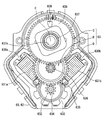
- It is a top view which shows the inside of the step motor by 1st embodiment.
- It is a perspective view which shows the inside of the step motor by 1st embodiment.
- FIG. 7 is a side view taken along line VIII-VIII in FIG. 6.
- FIG. 7 is a side view taken along line IX-IX in FIG. 6.
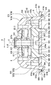
- It is a bottom view which shows the step motor by 1st embodiment.
- It is the XI-XI sectional view taken on the line of FIG.
- It is sectional drawing which expands and shows a part of FIG.
- It is a schematic diagram for demonstrating the function of the latching arm and latching claw by 1st embodiment.
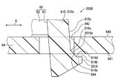
- It is sectional drawing which expands and shows a part of step motor by 2nd embodiment, Comprising: It is sectional drawing corresponding to FIG. It is sectional drawing which shows the modification of FIG.
- a step motor includes a motor body that gives a rotational driving force to a rotating body, a motor casing that houses the motor body, and a motor board that holds the motor casing.
- the motor board has a mounting surface on which the motor body is mounted via the motor casing, an opposite locking surface, and a locking hole penetrating between both surfaces.
- the motor casing has a locking arm inserted in a locking hole of the motor board in an elastically deformed state and a locking claw locked by the motor board.
- the locking arm is in contact with the inner surface of the locking hole along the direction perpendicular to both surfaces of the motor substrate, and the locking claw is locked to the locking surface along the direction parallel to both surfaces of the substrate. Abut.
- the locking arm is in an elastically deformed state, so that a load in the parallel direction acts at the contact position of the locking arm with respect to the inner surface of the locking hole, whereas at the contact position of the locking claw with respect to the locking surface.
- a vertical load is applied.
- it is necessary to secure the length of the locking arm along the parallel direction, and there is a concern that downsizing is hindered. It was.
- the pointer instrument 1 for a vehicle As shown in FIGS. 1 and 2, the pointer instrument 1 for a vehicle according to the first embodiment of the present disclosure is installed on an instrument panel in the vehicle.
- the vehicle pointer instrument 1 includes a display member 2, a rotation pointer 4, and a step motor 6.
- viewing side means the side where the display of the instrument 1 is visually recognized by a passenger on the driver's seat in the vehicle
- anti-viewing side means “the viewing side”. Means the other side.
- the display member 2 is formed by laminating a light-shielding printing layer on a translucent substrate such as polycarbonate resin, and has a flat plate shape as a whole.
- the display surface 2a which is one surface of the display member 2 is arranged toward the viewing side.
- an opening portion of the light-shielding print layer is formed by using numbers and scales arranged in the rotation direction of the rotation pointer 4 as an index 20 in order to display “vehicle state value”.
- the “vehicle state value” in the present embodiment is a vehicle speed value as shown in FIG. 1, but may be a physical quantity related to the vehicle, such as an engine speed.
- a warning lamp 21 for issuing a warning is formed around the rotation shaft 41 of the rotation pointer 4 in the opening portion of the light shielding printing layer in the display member 2.
- the rotation pointer 4 as a “rotating body” is made of a translucent resin material such as acrylic resin, and has a pointer main body 40 and a rotation shaft 41.
- the pointer main body 40 has an elongated needle shape as a whole, and is disposed on the viewing side with respect to the display surface 2 a of the display member 2.
- the pointer main body 40 instructs the “vehicle state value” indicated by the index 20 according to the rotational position by the tip 40a.
- the rotating shaft 41 as a whole has a cylindrical shape extending from the base end 40 b of the pointer main body 40 toward the non-viewing side.
- the rotating shaft 41 is inserted into the pointer hole 22 that penetrates between both surfaces 2a and 2b in the display member 2.
- the rotating shaft 41 is connected to the step motor 6 on the side opposite to the visual recognition side from the back surface 2b of the display member 2. Accordingly, the step motor 6 realizes the above instruction by the pointer main body 40 by rotationally driving the rotation pointer 4 around the rotation center line C that is the axis of the rotation shaft 41.
- the step motor 6 is disposed on the counter-viewing side with respect to the back surface 2 b of the display member 2.
- the step motor 6 includes a motor casing 60, a motor main body 63, a motor substrate 64, and light sources 65 and 66.
- the motor casing 60 is formed by combining a pair of case members 61 and 62, and has a hollow shape as a whole.
- Each case member 61, 62 is formed of a light-shielding resin material such as a modified polyphenylene ether resin (m-PPE), and is formed in a cup shape.
- the case members 61 and 62 are coupled to each other by snap-fit fitting in a state where the opening edge portions 610 and 620 are overlapped with each other.
- Each of the case members 61 and 62 has through holes 612 and 622 that pass through the bottom portions 611 and 621 on the rotation center line C of the pointer main body 40.
- the first case member 61 is disposed to face the back surface 2b on the counter-viewing side of the display member 2.
- the second case member 62 is disposed on the opposite side of the first case member 61.
- the motor board 64 is formed by laminating a metal wiring layer on a printed board such as a glass epoxy board, and has a flat plate shape as a whole.
- the motor substrate 64 is disposed on the opposite side of the motor casing 60.
- the mounting surface 640 that is one surface on the viewing side of the motor substrate 64 has a planar shape.
- a motor casing 60 and light sources 65 and 66 are held on the mounting surface 640.
- the motor body 63 is accommodated in the motor casing 60. Thereby, the motor main body 63 is mounted on the mounting surface 640 of the motor substrate 64 via the motor casing 60.
- the motor body 63 includes a drive source D, a speed reduction mechanism R, and a rotation output mechanism O.
- the drive source D is a combination of the yoke 630, the two-phase coils 631 a and 631 b and the magnet rotor 632, and is arranged away from the rotation center line C of the pointer body 40 in the radial direction.
- the yoke 630 is formed in a frame shape from a magnetic metal material such as iron and is fixed to the motor casing 60.
- the yoke 630 has a pair of magnetic poles 630a and 630b protruding to the inner peripheral side.
- An A-phase coil 631a is wound around one magnetic pole 630a, and a B-phase coil 631b is wound around the other magnetic pole 630b.
- the coils 631a and 631b of the phases A and B are electrically connected to the metal wiring layer of the motor board 64 through a through hole that penetrates the second case member 62 of the motor casing 60.
- the magnet rotor 632 is formed in a disk shape from a magnetic metal material such as ferrite, and is disposed on the inner peripheral side of the yoke 630 with a gap between each of the magnetic poles 630a and 630b.
- the magnet rotor 632 is radially supported and thrust supported by the motor casing 60 so as to be rotatable about an axis substantially parallel to the rotation center line C of the pointer main body 40.
- N and S poles as magnetic poles are alternately magnetized in the rotation direction.
- the speed reduction mechanism R is a combination of a magnet gear 634, an idle gear 635, and a pinion gear 636, and is disposed radially away from the rotation center line C of the pointer body 40.
- the magnet gear 634 is made of a hard resin material such as polyacetal resin (POM) and has a spur gear shape.
- the magnet gear 634 is radially supported and thrust supported by the motor casing 60 so as to be integrally rotatable with the magnet rotor 632.
- the idle gear 635 and the pinion gear 636 are integrally formed coaxially with a hard resin material such as polybutylene terephthalate resin (PBT), and each has a spur gear shape.
- PBT polybutylene terephthalate resin
- the idle gear 635 and the pinion gear 636 are radially supported and thrust supported by the motor casing 60 so as to be integrally rotatable about an axis substantially parallel to the rotation center line C of the pointer main body 40.
- the idle gear 635 meshes with the magnet gear 634 to reduce the rotation of the gear 634.
- the rotation output mechanism O is composed of an output shaft 637, an output gear 638, and a rotation stopper 639, and is arranged on the rotation center line C of the pointer main body 40.
- the output shaft 637, the output gear 638, and the rotation stopper 639 are integrally formed of a hard resin material such as polyacetal resin (POM).
- POM polyacetal resin
- the output shaft 637, the output gear 638, and the rotation stopper 639 are radially supported and thrust supported by the motor casing 60 so as to be integrally rotatable about the rotation center line C of the pointer main body 40.
- the output shaft 637 has a cylindrical shape as a whole.
- the rotation shaft 41 of the rotation pointer 4 is press-fitted coaxially.
- the output shaft 637 rotates around the rotation center line C together with the rotation pointer 4 to output a rotational driving force to the pointer 4.
- the output gear 638 has a spur gear shape extending from the output shaft 637 to the outer peripheral side. As shown in FIGS. 2, 4, and 5, the output gear 638 meshes with the pinion gear 636 of the speed reduction mechanism R to reduce the rotation of the gear 636.
- the rotation stopper 639 has a protruding piece shape protruding from the output gear 638 to the viewing side.
- the rotation stopper 639 is provided so as to be locked by a fixed stopper of the motor casing 60 at the limit positions on both sides that determine the rotation range of the rotation pointer 4. As a result, even if a rotational driving force is applied from the rotation output mechanism O to the rotation pointer 4, the rotation of the pointer 4 outside the rotation range is limited.
- the rotating body illumination light source 65 is disposed on the rotation center line C of the pointer main body 40 in the through hole 622 of the second case member 62 and mounted on the mounting surface 640 of the motor board 64. ing.
- the rotating body illumination light source 65 is mainly composed of LEDs (Light-Emitting-Diodes) and is electrically connected to the metal wiring layer of the motor board 64.
- the rotating body illumination light source 65 emits light when energized from an external control circuit through the metal wiring layer.
- the light emitted from the rotating body illumination light source 65 passes through the through hole 622 of the second case member 62 and the center hole 637a of the output shaft 637 and is incident on the rotating shaft 41 of the rotating pointer 4, thereby Guided to the pointer body 40. Thereby, the rotation pointer 4 is illuminated through the motor main body 63, so that the pointer main body 40 is visually recognized in a light-emitting state.
- a plurality of display illumination light sources 66 are arranged around the second case member 62 and mounted on the mounting surface 640 of the motor substrate 64.
- Each display illumination light source 66 is mainly composed of LEDs, and is electrically connected to the metal wiring layer of the motor board 64.
- Each display illumination light source 66 emits light when energized at the time of a necessary warning from an external control circuit via a metal wiring layer. The light emitted from the display illumination light source 66 passes through the periphery of the motor casing 60 and enters the display member 2. As a result, the display member 2 is directly illuminated so that the warning lamp 21 emits light when a necessary warning is issued.
- the display illumination light source 66 is arranged on the mounting surface 640 of the motor board 64 as close as possible to the motor casing 60. Therefore, in order to properly open an optical path L (see FIG. 7) from the display illumination light source 66 side to the display member 2 side in the motor casing 60, the first case member 61 of the casing 60 has FIGS. , 6 to 9, a plurality of chamfered portions 613 are provided. Each chamfered portion 613 is chamfered from the bottom portion 611 to the side wall portion 614 in the first case member 61. Each chamfered portion 613 has a planar shape (that is, a slope shape) that is inclined with respect to the rotation center line C and the mounting surface 640. Here, each chamfered portion 613 of the present embodiment is inclined toward the rotation center line C side toward the viewing side.
- the motor substrate 64 has a mounting surface 640 and a locking surface 641 and a locking hole 642.
- the locking surface 641 has a planar shape substantially parallel to the surface 640 as a surface on the viewing side opposite to the mounting surface 640 in the motor substrate 64.
- One locking hole 642 is provided on each of both sides of the rotating body illumination light source 65 on the rotation center line C in the reference direction B.
- Each locking hole 642 penetrates between the mounting surface 640 and the locking surface 641 in the motor board 64 substantially perpendicularly to the both surfaces 640 and 641.
- each locking hole 642 of the present embodiment has a straight rectangular hole shape along the rotation center line C.
- each locking hole 642 forms a ridge-shaped locking corner 644 between the locking surface 641 and a substantially right angle in the longitudinal section.
- the first case member 61 of the motor casing 60 integrally includes a set of a locking arm 615 and a locking claw 616.
- One set of the locking arm 615 and the locking claw 616 is provided on both sides of the rotating body illumination light source 65 on the rotation center line C in the reference direction B. That is, the set of the locking arm 615 and the locking claw 616 is provided on both sides of the rotating body illumination light source 65 on the virtual plane A (see FIGS. 6, 9, and 10) along the reference direction B. .
- each locking arm 615 is formed in an elastic spring shape having a rectangular cross section that is bent in one step.
- the base portion 615 a of each locking arm 615 extends obliquely from the side wall portion 614 to the non-viewing side in the first case member 61.
- the elastic arm portion 615b of each locking arm 615 is bent from the base portion 615a in the first case member 61 and extends obliquely toward the non-viewing side.
- the elastic arm portions 615b are inserted into the corresponding locking holes 642 from the viewing side and penetrate through to the non-viewing side.
- each locking arm 615 of the present embodiment is inclined toward the outside in the reference direction B toward the counter-viewing side in the inserted state into the corresponding locking hole 642.
- Each locking claw 616 has a hook shape protruding from the same pair of locking arms 615 to the outer peripheral side in the first case member 61. As shown in FIGS. 6, 8, 9, 11, and 12, each locking claw 616 forms a contact surface 616 a and a facing surface 616 b.
- each locking claw 616 the contact surface 616a bends from an inclined surface 615c facing outward in the reference direction B in the same set of elastic arm portions 615b and extends toward the counter-viewing side and the outer facing surface 616b. ing.
- the contact surface 616a of each locking claw 616 extends in a planar shape (that is, a slope shape) that is inclined with respect to the rotation center line C and both surfaces 640 and 641 of the motor substrate 64.
- the contact surface 616a is inclined toward the outer side in the reference direction B toward the non-viewing side while the same set locking arm 615 is inserted into the corresponding locking hole 642. ing.
- the inclination angle ⁇ a formed by the contact surface 616a with both surfaces 640 and 641 of the motor board 64 in each locking claw 616 is the same as the inclined surfaces 615c of both surfaces 640 and 641 in the same set of locking arms 615.
- An angle smaller than the tilt angle ⁇ b is set to be ideally 45 ° in the present embodiment.
- each latching claw 616 gives the restoring force generated by the same pair of latching arms 615 that are elastically deformed to the latching corner portion 644 that abuts as shown in FIG.
- the parallel direction X substantially coincides with the reference direction B in the present embodiment
- the abutting surface 616a is an intermediate portion between the boundary portions 616c and 616d with the locking arm 615 and the opposing surface 616b of the same set.
- the size is formed so as to abut against the corresponding locking corner portion 644.
- each locking claw 616 shown in FIGS. 8, 9, 11, and 12 the opposing surface 616b is bent from the contact surface 616a and extends outward in the reference direction B.
- the opposing surface 616b of each locking claw 616 is a plane that faces the locking surface 641 of the motor board 64 on the opposite side of the elastic arm portion 615b of the same set locking arm 615 across the contact surface 616a.
- the opposing surface 616b ideally opens the predetermined clearance 616e with the locking surface 641 in a state where the same set locking arm 615 is inserted into the corresponding locking hole 642. Opposes substantially parallel.
- the second case member 62 of the motor casing 60 has a bank protrusion 624 dispersed in a plurality of locations around the rotating body illumination light source 65 on the rotation center line C.
- the bank protrusions 624 are arranged at substantially equal intervals around the rotating body illumination light source 65 so as to avoid the virtual plane A (see FIGS. 9 and 10) and the vicinity thereof along the reference direction B.
- Each bank protrusion 624 protrudes slightly from the bottom 621 of the second case member 62 toward the non-viewing side, and a protruding tip end surface 624a is formed in a planar shape that can come into surface contact with the mounting surface 640 of the motor board 64.
- each bank protrusion 624 of the present embodiment has an arcuate wall shape extending around the rotation center line C.
- Each bank protrusion 624 having such a configuration is in contact with the mounting surface 640 in a surface contact state.
- the ridge protrusions 624 adjacent in the circumferential direction around the rotation center line C have a gap 625 as a space sandwiched between the bottom 621 and the motor substrate 64 as shown in FIGS. Opened.
- the second case member 62 of the motor casing 60 includes positioning protrusions 626 on both sides of the rotating body illumination light source 65 on the rotation center line C in the reference direction B.
- Each positioning projection 626 protrudes from the bottom 621 of the second case member 62 to the non-viewing side with a thickness equal to or greater than the thickness of the motor substrate 64.
- each positioning protrusion 626 of the present embodiment has a straight cylindrical pin shape along the rotation center line C.
- the motor board 64 has one positioning hole 646 at a position corresponding to the positioning protrusion 626 on both sides of the rotating body illumination light source 65 on the rotation center line C in the reference direction B.
- Each positioning hole 646 penetrates between the mounting surface 640 and the locking surface 641 in the motor board 64 substantially perpendicularly to the both surfaces 640 and 641.
- each positioning hole 646 of the present embodiment has a straight cylindrical hole shape along the rotation center line C.
- each positioning hole 646 the corresponding positioning protrusion 626 is fitted and inserted coaxially, so that the second case member 62 is positioned and held on the motor substrate 64.
- the set of the positioning projection 626 and the positioning hole 646 that exhibits the positioning function is provided on each side of the rotating body illumination light source 65 on the rotation center line C in the reference direction B.
- the set of the positioning protrusion 626 and the positioning hole 646 is more than the set of the locking arm 615 and the locking claw 616 on the corresponding side in the reference direction B. Is also arranged in the vicinity of the rotating body illumination light source 65.
- the positioning protrusion 626 of the present embodiment is aligned and disposed in the gap 625a located on the virtual plane A (see FIG. 10) along the reference direction B in the gap 625 between the bank protrusions 624. Yes.
- the locking claw 616 that is locked to the motor substrate 64 in the motor casing 60 has the mounting surface 640 of the substrate 64 and the contact surface 616a that extends obliquely with respect to the locking surface 641. 64 is brought into contact with a locking corner portion 644 formed by the locking surface 641 and the locking hole 642. According to this, the locking corner portion 644 is inserted by inserting the locking arm 615 into the locking hole 642 so as to be in an elastically deformed state extending obliquely with respect to the mounting surface 640 and the locking surface 641 of the motor substrate 64.
- Necessary loads Fx and Fy can be applied to the parallel direction X and the vertical direction Y with respect to the both surfaces 640 and 641 at the contact portion of the contact surface 616a with respect to the contact surface 616a. Therefore, when the seismic strength is increased by the mounting structure 8 of the motor main body 63 on the motor board 64 via the motor casing 60, it can be released from the need to secure the length of the locking arm 615 along the parallel direction X. . As described above, it is possible to reduce the size of the mounting structure 8 that improves the durability.
- the length of the locking arm 615 that extends obliquely is set so as to suppress the necessary loads Fx and Fy in the parallel direction X and the vertical direction Y to a level necessary for securing the seismic strength. be able to. According to such a setting, load variation due to manufacturing tolerances of the contact surface 616a and the locking corner portion 644 forming the contact state can be suppressed to be small, so that the design for ensuring seismic strength to improve durability is achieved. Becomes easy.
- a facing surface 616b is formed to face the locking surface 641 of the motor board 64. Become. According to this, even if the locking arm 615 tries to escape from the locking hole 642, the opposing surface 616 b is locked by the locking surface 641 and the escape is restricted, so that the locking arm 615 contacts the locking corner 644. The contact state of the surface 616a can be maintained. Therefore, the downsized mounting structure 8 can ensure seismic strength and improve durability.
- the abutment surface 616a abuts against the engagement corner portion 644 between the boundary portions 616c and 616d of the abutment surface 616a and each of the engagement arm 615 and the opposing surface 616b, thereby being parallel.
- the necessary loads Fx and Fy can be reliably applied to both the direction X and the vertical direction Y. According to this, it is possible to secure the seismic strength in both directions X and Y by the downsized mounting structure 8 and improve the durability.
- the necessary loads Fx and Fy having substantially the same magnitude can be applied to the parallel direction X and the vertical direction Y. According to this, it is possible to guarantee the seismic strength against both the vibration in the parallel direction X and the vibration in the vertical direction Y by the downsized mounting structure 8 and to increase the reliability of the durability improvement effect. .
- the rotating body illumination light source 65 is mounted on the mounting surface 640 of the motor substrate 64 together with the motor casing 60. Therefore, the illumination of the rotating pointer 4 by the emitted rotating body illumination light source 65 is realized through the motor body 63 mounted on the motor board 64 via the motor casing 60 by the mounting structure 8 in which the seismic strength can be secured. become. According to this, it becomes possible to stabilize the illumination state of the rotation pointer 4 by effectively utilizing the small mounting structure 8 that improves the durability.
- the function of the combination of the locking arm 615 and the locking claw 616 can be exhibited on both sides of the rotating body illumination light source 65 in the reference direction B. The effect can be promoted.
- the positioning projections 626 of the motor casing 60 and the positioning holes 646 of the motor board 64 are fitted on both sides of the rotating body illumination light source 65 in the reference direction B, so that the motor casing. 60 is positioned on the motor board 64.
- the seismic strength is ensured by the combination of the locking arms 615 and the locking claws 616 on both sides, and the positioning of the rotating body illumination light source 65 with respect to the motor main body 63 is positioned on both sides.
- This can be achieved by the combination of the protrusion 626 and the positioning hole 646. Therefore, the lighting state can be stabilized independently of the durability enhancement effect and the promotion of the miniaturization effect.
- the set of the positioning projection 626 and the positioning hole 646 is more than the set of the locking arm 615 and the locking claw 616 on both sides of the rotating body illumination light source 65 in the reference direction B, respectively.
- the bank protrusions 624 that are distributed and protruded at a plurality of locations around the rotating body illumination light source 65 in the motor casing 60 are in surface contact with the mounting surface 640 of the motor substrate 64, thereby providing a gap 625 between them. Open. According to this, the plurality of ridge protrusions 624 are pressed against the mounting surface 640 in a surface contact state to increase the seismic strength against vibration in the vertical direction Y, and the rotating body illumination light source 65 is connected through the gap 625 between the ridge protrusions 624. Heat can be released. Therefore, not only the durability due to vibration but also the durability due to heat can be improved.
- the positioning projections 626 are arranged by effectively utilizing the gaps 625 between the bank projections 624 on both sides of the rotating body illumination light source 65 in the reference direction B, the size can be reduced. Promotion becomes possible.
- the display member 2 that displays the vehicle state value indicated by the rotation pointer 4 is illuminated by the light emitted from the display illumination light source 66 mounted on the mounting surface 640 of the motor board 64.
- the chamfered portion 613 is chamfered so as to open an optical path L from the light source 66 side to the display member 2 side. According to this, while the display illumination light source 66 is disposed close to the motor casing 60 to promote downsizing, the illumination efficiency of the display member 2 is avoided by preventing the light from the light source 66 from being blocked by the motor casing 60. Can be increased.
- the second embodiment of the present disclosure is a modification of the first embodiment.
- the abutment surface 2616a of each locking claw 2616 is formed in a textured surface provided with minute irregularities (for example, 100 ⁇ m size).
- minute irregularities for example, 100 ⁇ m size.
- the required loads Fx and Fy are applied to both the parallel direction X and the vertical direction Y by contacting the corresponding locking corner portion 644 between the boundary portions 616c and 616d.
- the location of the contact to be applied is difficult to shift. According to this, it is possible to guarantee the seismic strength against both the vibration in the parallel direction X and the vibration in the vertical direction Y by the downsized mounting structure 2008, and to increase the reliability of the durability improvement effect. .
- the contact surfaces 616a and 2616a are brought into contact with the locking corners 644 at one of the boundary portions 616c and 616d between the contact arms 615 and the opposing surfaces 616b and the contact surfaces 616a and 2616a. You may let them.
- the contact surfaces 616a and 2616a may be formed so as to spread with an inclination angle ⁇ a of less than 45 ° or more than 45 ° with respect to both surfaces 640 and 641 of the motor substrate 64.
- the rotating body illumination light source 65 may be arranged so as to illuminate the rotation pointer 4 via a location different from the motor body 63. In the fifth modification, the rotating body illumination light source 65 may not be provided. In the modified example 6, three or more sets of the locking arm 615 and the locking claw 616 may be arranged around the rotating body illumination light source 65 on the rotation center line C, for example, at substantially equal intervals.
- the positioning projection 626 may be provided in the motor substrate 64 while the positioning hole 646 may be provided in the motor casing 60 as shown in FIG. 15.
- the set of the positioning protrusion 626 and the positioning hole 646 may be arranged away from the rotating body illumination light source 65 in the reference direction B than the set of the locking arm 615 and the locking claw 616.
- three or more sets of the positioning protrusion 626 and the positioning hole 646 may be arranged around the rotating body illumination light source 65 on the rotation center line C, for example, at substantially equal intervals.
- the set of the positioning protrusion 626 and the positioning hole 646 may not be provided.
- a set of the positioning protrusion 626 and the positioning hole 646 may be arranged avoiding the gap 625 (625a) between the bank protrusions 624.
- the bottom portion 621 of the second case member 62 may be directly brought into contact with the mounting surface 640 of the motor board 64 without providing the bank protrusion 624.
- the chamfered portion 613 may not be provided in the first case member 61.
- the display illumination light source 66 may not be provided.
- the present disclosure may be applied to a device other than the pointer instrument 1 for a vehicle such as a head-up display (HUD), and the “rotary body” of the device may be rotationally driven by the step motor 6.
- HUD head-up display
- the locking arm 615 may be extended substantially perpendicularly to the both surfaces 640 and 641 of the motor substrate 64.
- the locking claw 616 may be deformed so that the locking surface 641 of the motor substrate 64 and the inner surface of the locking hole 642 are in contact with each other.
- the step motor 6 described above drives the rotating body 4 to rotate.
- the step motor 6 includes a motor main body 63 that applies a rotational driving force to the rotating body, a motor casing 60 that houses the motor main body, and a motor substrate 64 that holds the motor casing.
- the motor board includes a mounting surface 640 on which the motor main body is mounted via a motor casing, a locking surface 641 opposite to the mounting surface, and a locking hole 642 penetrating between the mounting surface and the locking surface. And having.
- the motor casing has a locking arm 615 and locking claws 616 and 2616. The locking arm 615 is inserted into the locking hole in an elastically deformed state extending obliquely with respect to the mounting surface and the locking surface.
- the locking claws 616 and 2616 form contact surfaces 616a and 2616a that extend obliquely with respect to the mounting surface and the locking surface, and contact the locking corner portion 644 formed by the locking surface and the locking hole on the motor board.
- the contact surface is in contact with the motor substrate.
- the above-described configuration includes the step motor 6 and the rotation pointer 4 that indicates a vehicle state value as a rotating body.
- the locking claw that is locked to the motor substrate in the motor casing has the mounting surface of the substrate and the contact surface that extends obliquely with respect to the locking surface. It is made to contact
Landscapes
- Engineering & Computer Science (AREA)
- Power Engineering (AREA)
- Physics & Mathematics (AREA)
- General Physics & Mathematics (AREA)
- Chemical & Material Sciences (AREA)
- Combustion & Propulsion (AREA)
- Transportation (AREA)
- Mechanical Engineering (AREA)
- Instrument Panels (AREA)
- Motor Or Generator Frames (AREA)
- Details Of Measuring Devices (AREA)
Abstract
La présente invention concerne un moteur pas à pas (6) qui comprend un corps principal de moteur (63) qui applique une force d'entraînement en rotation à un corps rotatif (4) ; un carter de moteur (60) logeant le corps principal de moteur ; et une plaque de base de moteur (64) maintenant le boîtier de moteur. La plaque de base de moteur comporte : une surface de montage (640) sur laquelle le corps principal de moteur est monté par l'intermédiaire du carter de moteur ; une surface de verrouillage (641) sur le côté opposé à la surface de montage ; et des trous de verrouillage (642) pénétrant entre la surface de montage et la surface de verrouillage. Le carter de moteur comporte des bras de verrouillage (615) et des crochets de verrouillage (616, 2616). Les bras de verrouillage sont insérés dans les trous de verrouillage dans un état élastiquement déformé dans lequel les bras de verrouillage sont étendus diagonalement par rapport à la surface de montage et à la surface de verrouillage. Les crochets de verrouillage : forment des surfaces de contact (616a, 2616a) qui s'étendent diagonalement par rapport à la surface de montage et à la surface de verrouillage ; et sont verrouillés sur la plaque de base de moteur dans un état dans lequel les surfaces de contact sont amenées à venir en contact avec des sections de coin de verrouillage (644) formées par la surface de verrouillage et les trous de verrouillage dans la plaque de base de moteur.
Priority Applications (2)
| Application Number | Priority Date | Filing Date | Title |
|---|---|---|---|
| KR1020197018979A KR102178093B1 (ko) | 2017-04-13 | 2018-03-05 | 스텝 모터 및 차량용 지침 계기 |
| US16/514,076 US20190337387A1 (en) | 2017-04-13 | 2019-07-17 | Step motor and vehicular indicator instrument |
Applications Claiming Priority (2)
| Application Number | Priority Date | Filing Date | Title |
|---|---|---|---|
| JP2017-079884 | 2017-04-13 | ||
| JP2017079884A JP6652102B2 (ja) | 2017-04-13 | 2017-04-13 | ステップモータ及び車両用指針計器 |
Related Child Applications (1)
| Application Number | Title | Priority Date | Filing Date |
|---|---|---|---|
| US16/514,076 Continuation US20190337387A1 (en) | 2017-04-13 | 2019-07-17 | Step motor and vehicular indicator instrument |
Publications (1)
| Publication Number | Publication Date |
|---|---|
| WO2018190027A1 true WO2018190027A1 (fr) | 2018-10-18 |
Family
ID=63792852
Family Applications (1)
| Application Number | Title | Priority Date | Filing Date |
|---|---|---|---|
| PCT/JP2018/008209 Ceased WO2018190027A1 (fr) | 2017-04-13 | 2018-03-05 | Moteur pas à pas et instrument indicateur pour véhicules |
Country Status (4)
| Country | Link |
|---|---|
| US (1) | US20190337387A1 (fr) |
| JP (1) | JP6652102B2 (fr) |
| KR (1) | KR102178093B1 (fr) |
| WO (1) | WO2018190027A1 (fr) |
Cited By (1)
| Publication number | Priority date | Publication date | Assignee | Title |
|---|---|---|---|---|
| US20220196020A1 (en) * | 2020-12-23 | 2022-06-23 | Stephan Karns | Electronic extension module foer electric pump |
Families Citing this family (4)
| Publication number | Priority date | Publication date | Assignee | Title |
|---|---|---|---|---|
| JP6857995B2 (ja) * | 2016-10-21 | 2021-04-14 | 日本電産サンキョー株式会社 | カバーの固定構造、およびモータ |
| JP6733593B2 (ja) * | 2017-04-13 | 2020-08-05 | 株式会社デンソー | ステップモータ及び車両用指針計器 |
| JP7264924B2 (ja) * | 2021-02-12 | 2023-04-25 | 矢崎総業株式会社 | 投影装置 |
| FR3139251A1 (fr) * | 2022-08-26 | 2024-03-01 | Sonceboz Automotive Sa | Motoréducteur à compacité amélioré |
Citations (4)
| Publication number | Priority date | Publication date | Assignee | Title |
|---|---|---|---|---|
| JP2001041777A (ja) * | 1999-07-30 | 2001-02-16 | Nippon Seiki Co Ltd | 計器装置 |
| JP2004248356A (ja) * | 2003-02-12 | 2004-09-02 | Calsonic Kansei Corp | モータの取付け構造 |
| WO2006120515A1 (fr) * | 2005-05-12 | 2006-11-16 | Societe Industrielle De Sonceboz S.A. | Actionneur pour indicateurs de mesures |
| JP2012220442A (ja) * | 2011-04-13 | 2012-11-12 | Yazaki Corp | 計器ユニットの固定構造 |
Family Cites Families (1)
| Publication number | Priority date | Publication date | Assignee | Title |
|---|---|---|---|---|
| JP4398264B2 (ja) | 2004-01-20 | 2010-01-13 | 矢崎総業株式会社 | 電気固定構造 |
-
2017
- 2017-04-13 JP JP2017079884A patent/JP6652102B2/ja active Active
-
2018
- 2018-03-05 WO PCT/JP2018/008209 patent/WO2018190027A1/fr not_active Ceased
- 2018-03-05 KR KR1020197018979A patent/KR102178093B1/ko active Active
-
2019
- 2019-07-17 US US16/514,076 patent/US20190337387A1/en not_active Abandoned
Patent Citations (4)
| Publication number | Priority date | Publication date | Assignee | Title |
|---|---|---|---|---|
| JP2001041777A (ja) * | 1999-07-30 | 2001-02-16 | Nippon Seiki Co Ltd | 計器装置 |
| JP2004248356A (ja) * | 2003-02-12 | 2004-09-02 | Calsonic Kansei Corp | モータの取付け構造 |
| WO2006120515A1 (fr) * | 2005-05-12 | 2006-11-16 | Societe Industrielle De Sonceboz S.A. | Actionneur pour indicateurs de mesures |
| JP2012220442A (ja) * | 2011-04-13 | 2012-11-12 | Yazaki Corp | 計器ユニットの固定構造 |
Cited By (2)
| Publication number | Priority date | Publication date | Assignee | Title |
|---|---|---|---|---|
| US20220196020A1 (en) * | 2020-12-23 | 2022-06-23 | Stephan Karns | Electronic extension module foer electric pump |
| US12212041B2 (en) * | 2020-12-23 | 2025-01-28 | Wilo Se | Electronic extension module for electric pump |
Also Published As
| Publication number | Publication date |
|---|---|
| JP2018179768A (ja) | 2018-11-15 |
| KR20190084329A (ko) | 2019-07-16 |
| JP6652102B2 (ja) | 2020-02-19 |
| US20190337387A1 (en) | 2019-11-07 |
| KR102178093B1 (ko) | 2020-11-12 |
Similar Documents
| Publication | Publication Date | Title |
|---|---|---|
| WO2018190027A1 (fr) | Moteur pas à pas et instrument indicateur pour véhicules | |
| CN110073581B (zh) | 步进马达以及车辆用指针仪表 | |
| CN114787686B (zh) | 光扫描装置 | |
| JP6665668B2 (ja) | トルク検出装置 | |
| JP5522186B2 (ja) | 表示装置 | |
| JP5788747B2 (ja) | 計器ユニット | |
| CN111094796A (zh) | 驱动装置及用于平视显示装置的驱动装置 | |
| US11274730B2 (en) | Step motor and indicator instrument for vehicle | |
| JP2007276707A (ja) | 自動車用のアクセルペダルユニット | |
| JP6831810B2 (ja) | 車両表示装置用指針 | |
| JP2011223776A (ja) | 計器ユニット | |
| JP2014153277A (ja) | 車両用計器の指針体 | |
| JP5288257B2 (ja) | 表示装置 | |
| JP2019066197A (ja) | 車両用指針計器 | |
| JP5594823B2 (ja) | 指針ユニット | |
| JP6790649B2 (ja) | 面発光装置および表示装置 | |
| JP4572694B2 (ja) | 表示装置 | |
| JP5382338B2 (ja) | 表示装置 | |
| JP5418483B2 (ja) | 車両用メータ | |
| JPS6256920A (ja) | 光走査装置 | |
| JP5524706B2 (ja) | 計器ユニット | |
| JP2012032244A (ja) | 計器用指針、及び計器 | |
| JP5349400B2 (ja) | 操作ノブ保持構造 | |
| JPH11237258A (ja) | 指示計器 | |
| JPH0738973U (ja) | クロスコイル形指示計器ユニット |
Legal Events
| Date | Code | Title | Description |
|---|---|---|---|
| 121 | Ep: the epo has been informed by wipo that ep was designated in this application |
Ref document number: 18784318 Country of ref document: EP Kind code of ref document: A1 |
|
| ENP | Entry into the national phase |
Ref document number: 20197018979 Country of ref document: KR Kind code of ref document: A |
|
| NENP | Non-entry into the national phase |
Ref country code: DE |
|
| 122 | Ep: pct application non-entry in european phase |
Ref document number: 18784318 Country of ref document: EP Kind code of ref document: A1 |