WO2018190045A1 - Support de jardinière capturant l'eau - Google Patents
Support de jardinière capturant l'eau Download PDFInfo
- Publication number
- WO2018190045A1 WO2018190045A1 PCT/JP2018/009044 JP2018009044W WO2018190045A1 WO 2018190045 A1 WO2018190045 A1 WO 2018190045A1 JP 2018009044 W JP2018009044 W JP 2018009044W WO 2018190045 A1 WO2018190045 A1 WO 2018190045A1
- Authority
- WO
- WIPO (PCT)
- Prior art keywords
- packing
- water receiving
- top plate
- water
- hole
- Prior art date
- Legal status (The legal status is an assumption and is not a legal conclusion. Google has not performed a legal analysis and makes no representation as to the accuracy of the status listed.)
- Ceased
Links
Images




Classifications
-
- A—HUMAN NECESSITIES
- A01—AGRICULTURE; FORESTRY; ANIMAL HUSBANDRY; HUNTING; TRAPPING; FISHING
- A01G—HORTICULTURE; CULTIVATION OF VEGETABLES, FLOWERS, RICE, FRUIT, VINES, HOPS OR SEAWEED; FORESTRY; WATERING
- A01G9/00—Cultivation in receptacles, forcing-frames or greenhouses; Edging for beds, lawn or the like
- A01G9/04—Flower-pot saucers
Definitions
- the present invention relates to a pot stand that can easily treat waste water from the pot bottom when watering potted plants and the like.
- a dish is placed under the pot where the foliage plants are planted to receive the wastewater that comes out of the bottom of the pot when the pot plants are watered.
- the capacity of the dish to receive waste water is basically small, and there is a risk that the waste water will spill out of the dish, so that watering of the plant tends to be insufficient.
- the waste water from the bowl may be moved to a place where it may spill (for example, outdoors or bathroom). Since it becomes heavy, it is difficult to lift and move the bowl from the dish. Further, it is troublesome to treat waste water and dirt accumulated in the dish.
- Patent Document 1 proposes a water-mounted plant pot stand (hereinafter referred to as a pot stand) having a water collection tray for receiving waste water.
- a part for placing a pot hereinafter referred to as part A
- part A covers the bottom of the bowl, and a hole can be provided in the center of the part A corresponding to the hole.
- a funnel-type saucer of the form is provided, and after draining, the waste water coming out of the pot bottom passes through the funnel-type saucer and the waste water flows down to the water collection tray provided under the funnel-type saucer It is.
- Patent Document 2 proposes a flower pot with a pot with a hole and a waterproof drawer provided under the table.
- the funnel-shaped top plate in which the bowl disclosed in Patent Document 1 is placed is a flat top plate, the top plate is provided with a hole, and a water receiving / drawing drawer is provided under the top plate. Waste water that has come out from the bottom passes through the hole in the top plate, and the water receiving drawer provided under the top plate is changed to a structure that receives waste water.
- the versatility of the pots that can be used increases, the following problems still remain.
- FIG. 15 is a cross-sectional view showing a state in which a top plate hole 425 is provided in the top plate of the water receiving body 402 including the housing 421 and the top plate 422 and a bowl is placed on the surface of the top plate. Moreover, the flow of the waste water which came out of the pot waste water hole of the pot bottom is shown by the dashed-two dotted line which shows the flow of the waste water W.
- the top plate becomes dirty and impairs the aesthetic effect, and also flows out of the water receiving body. This may result in soiling of furniture and the like, and thus labor and time for processing the waste water W1 is generated.
- Patent Document 2 does not disclose a specific method for wastewater treatment, and has the same problem as that of Patent Document 1.
- An object is to provide a pot with a water receiving function.
- the present invention has been made in view of the above problems, and the invention according to claim 1 is a pot table with a water receiving function including a water receiving body and an inverted conical packing provided on the surface of the water receiving body.
- the water receiving body includes a top plate for placing a bowl having a top plate hole, a water receiving drawer provided below the top plate hole, and a housing for storing the water receiving drawer,
- the inverted conical packing includes an inverted conical packing body that receives waste water from the bowl and discharges it downward from the packing hole, and a packing base that protrudes outward from the outer peripheral wall outer surface of the lower end of the packing body,
- the top plate hole and the packing hole communicate with each other, and the packing body is elastically deformed by the weight of the bowl placed on the upper part of the packing body.
- the inverted conical packing receives waste water from the bowl, the waste water flows from the packing hole through the top plate hole to the water receiving drawer, and the water receiving drawer can receive the waste water.
- the packing body is pressed against the back surface of the bowl bottom, and at the same time, the packing body is elastically deformed by the weight of the bowl. It can cope with.
- the elastically deformed inverted conical packing steadily prevents waste water from flowing to the top plate surface.
- the water receiving capacity of the water receiving / drawing to be large, it is possible to significantly increase the amount of waste water received from a dish used as a general method for receiving waste water.
- the inverted conical packing can perform a waterproof function corresponding to the shape of the bowl bottom.
- the invention described in claim 2 is characterized in that, in the bowl base with a water receiving function according to claim 1, the thickness of the packing base is larger than the thickness of the packing body.
- the inner wall of the packing hole is prevented from warping, and the durability of the inverted conical packing and the inverted cone are prevented.
- the waterproofness by the shaped packing can be enhanced.
- the invention according to claim 3 is the pot base with a water receiving function according to claim 1 or 2, wherein the inverted conical packing further has a packing base back protrusion, and the packing base back protrusion is formed of the packing base. It is provided on the back surface, has a cylindrical shape, and has a hole communicating with the packing hole.
- the packing base back projection has a merit that the structure of the main body can be simplified in that the waste water flowing out through the top plate as a water leak can be controlled only by the inverted conical packing.
- the invention according to claim 4 is the basin with a water receiving function according to any one of claims 1 to 3, wherein a ring-shaped protrusion is provided around the top plate hole on the back surface of the top plate.
- the ring-shaped protrusion is annular and has a shape in which the lower end is narrowed.
- the invention according to claim 5 is the water proof stand with water receiving function according to any one of claims 1 to 4, wherein the water receiving body has a waterproof structure formed of a waterproof material. A case is provided.
- the invention according to claim 6 is the water basin with a water receiving function according to any one of claims 1 to 5, wherein the auxiliary water is further provided inside the water receiving body below the water receiving / drawing drawer.
- a receiving tray is provided.
- the invention according to claim 7 is the pot stand with a water receiving function according to any one of claims 1 to 6, wherein an annular groove is provided around the top plate hole on the back surface of the top plate. This is a bowl with a water receiving function.
- the waste water flowing through the top plate back surface is controlled without providing the ring-shaped projection or the reverse conical packing having the packing base back projection on the top plate back surface, and the waste water is It is possible to drain it into the drawer.
- the pot with a water receiving function of the present invention in the management of foliage plants, while increasing the aesthetic effect, it is possible to increase the allowable amount that can receive the waste water that comes out after watering, safety by preventing water leakage And wastewater treatment can be simplified.
- inverted conical packing is abbreviated as FP.
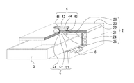
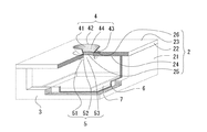
- FIG. 1 It is a perspective view of a pot stand appearance with a water receiving function of a first embodiment of the present invention. It is the perspective view which made FIG. 1 partial sectional drawing. It is the perspective view which excluded the water receiving / drawing-out of FIG.
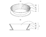
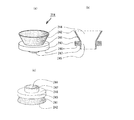
- A) is a perspective view of FP of the embodiment
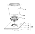
- (b) is a sectional view of the same. It is a perspective view which shows the positional relationship of the bowl of the same embodiment, a top plate, and FP. It is a perspective view in the state where the bowl of the embodiment was provided.
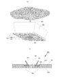
- (A), (b) is sectional drawing which shows the mode of FP by the shape of a different bowl bottom in the same embodiment.
- (A) is a perspective view which shows a ring-shaped protrusion
- (b) is the same sectional drawing. It is sectional drawing which shows the flow of the wastewater of the pot stand with a water receiving function of the embodiment.
- (A) is a perspective view of FP in 2nd Embodiment
- (b) is the same sectional drawing. It is a perspective view in the state where FP of the embodiment was provided in the top plate.
- (A), (c) is a perspective view of FP in 3rd Embodiment, (b) is the same sectional drawing. It is sectional drawing of the state with which FP of the embodiment was provided in the top plate.
- (A) is a perspective view which shows the annular groove in 4th Embodiment
- (b) is the same sectional drawing. It is sectional drawing of the bowl stand with a water receiving function of a prior art.
- FIG. 1 is a perspective view showing an external appearance of a pot stand 1 with a water receiving function according to the first embodiment of the present invention.
- the water receiving body 2 including the housing 21 and the top plate 22 is inserted into the housing 21 below the top plate 22 and the FP 4 described below on the top surface 23.
- a removable water receiving / drawing 3 is provided.
- the top plate 22 has a top plate hole 25, which will be described later, and a shape corresponding to the shape of the packing base 43 of the FP 4 around the top plate hole 25 and on the top plate surface 23, which will be described later.
- a hole surrounding groove 26 is provided.
- the depth of the groove 26 around the hole is equal to or greater than the thickness of the packing base of the FP4, it is desirable because the effect of preventing wastewater from flowing out to the top plate surface is increased.
- the depth of the hole surrounding groove 26 and the thickness of the packing base are the same, when the FP 4 is placed in the hole surrounding groove 26, the height of the packing base surface and the top plate surface becomes the same level, and the packing of the FP 4 Only the main body 41 is present above the top surface 23. Further, if the depth of the groove 26 around the hole is made larger than the sum of the thickness of the packing base and the thickness of the packing body 41, the packing body 41 is completely crushed as will be described later (FIG. 7A). ), The packing main body 41 can be prevented from coming out from the top plate surface.
- the water receiving drawer 3 is provided in a form to be inserted into the water receiving main body 2 and receives waste water falling from the top plate hole 25. Therefore, the inner surface of the water receiving / drawing 3 needs to be formed of a waterproof material or to be waterproofed.
- a water receiving vessel may be further prepared in the water receiving / drawing drawer 3 so that the vessel receives waste water. Then, when the waste water received by the water receiving / drawing 3 is treated, the waste water of the vessel in the water receiving / drawing is treated without necessarily removing the water receiving / drawing 3 from the water receiving body 2 completely. It is only necessary to perform wastewater treatment.
- the pot stand with a water receiving function is not only considered to be convenient for the treatment of waste water generated when watering a potted plant, but also has to consider the aesthetic effect of the appearance.
- the water receiving body 2 is a cube, but is not limited to this shape.
- the water receiving body 2 may have various shapes such as a rectangular parallelepiped, a columnar shape, a donut shape, and a geometric shape.
- the form of the water receiving body 2 varies depending on the design, such as a part of furniture design such as a cabinet or a book case, or a caster.
- FIG. 2 is a partial cross-sectional view of the water table with a water receiving function shown in FIG. 1, that the top plate hole and the packing hole communicate with each other, and that the top plate has a ring-shaped protrusion on the back surface, It is a perspective view which shows the state by which the waterproof process inside the main body was made
- the top plate hole 25 is provided in the top plate 22, and the FP 4 is in a form in which the top plate hole 25 and the packing hole 44 of the FP 4 communicate with each other and in the groove 26 around the hole.
- a packing base is provided to fit.
- the top plate 22 is provided with a ring-shaped protrusion 5 which will be described later in a form surrounding the top plate hole 25 on the back surface 24 of the top plate.
- the inside of the water receiving main body 2 is a configuration in which the top plate rear surface 24 and the inner surface of the housing 21 are configured.
- a waterproof case 6, which will be described later, is formed inside the water receiver main body 2 using a material having a waterproof effect.
- the water receiving / drawing 3 is provided in such a form that it is inserted into the waterproof case simultaneously with the water receiving main body 2.
- the waterproof case 6 enhances waterproofness so that waste water collected in the water receiving / drawing body 3 does not jump out of the water receiving body 2 when an impact or vibration is applied to the water receiving body 2.
- the waterproof case is made of an acrylic material and is formed in a rectangular parallelepiped shape. As long as the material can be changed. As an example, there is also means for waterproofing the inner surface of the water receiving body 2.
- the form of the waterproof case 6 corresponds to the form of the inner surface of the water receiving body 2, and the thickness of the waterproof case 6 is desirably thin as long as a waterproof effect can be obtained.
- FIG. 3 is a perspective view showing a state in which the water receiving / drawing-out is removed from the pot with a water receiving function shown in FIG. 2, and shows a state in which an auxiliary water receiving tray 7 is provided under the water receiving / drawing-out.
- auxiliary water receiving tray 7 (Explanation of auxiliary water receiving tray) The installation place of the auxiliary water receiving tray 7 is inside the water receiving main body 2, inside the waterproof case 6, and under the water receiving / drawing drawer 3. If the water receiver main body 2 does not include the waterproof case 6, the water receiver main body 2 is inside the water receiver main body 2 and below the water receiver drawer 3.
- the auxiliary water receiving tray 7 is provided inside the water receiving main body 2 to serve as a reserve when the water receiving / drawing 3 is temporarily removed because the water receiving / drawing 3 is disposed of the waste water.
- the auxiliary water receiving tray 7 since most of the waste water is received by the water receiving drawer 3, if the auxiliary water receiving tray 7 is provided in a compact size, the overall functionality and aesthetic effect can be enhanced.
- FIG. 4A is a perspective view of the FP in the first embodiment, and FIG. 4B is a cross-sectional view thereof.
- the FP 4 has a packing body 41, a packing base 43, and a packing hole 44 in the center of the lower part of the FP, and the cross section is narrowed in the direction from the outer periphery of the uppermost part 42 of the packing body to the packing base 43. It has an inverted conical shape. In this embodiment, the inclination of the packing body 41 is 30 degrees outward from the vertical.
- the material of FP4 is silicone rubber.
- the material for forming the FP4 can be appropriately changed as long as the packing body 41 is a material that can be elastically deformed, has water resistance, and can be pressure-bonded (adhered) to the surface of the bowl bottom. .
- the thickness of the packing base 43 and the packing body 41 of the FP 4 are both 3 mm.
- the thickness of the packing base is preferably 3 mm to 30 mm, more preferably 3 mm to 20 mm. This is because the top plate of furniture or the like is generally 30 mm or less, and when the thickness of the packing base exceeds 20 mm, it is difficult to fit the top plate.
- the thickness of the packing body is preferably 1 mm to 10 mm.
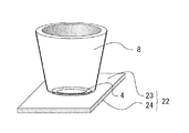
- FIG. 5 is a perspective view showing a positional relationship in which a bowl, a top plate, and an FP are provided in the bowl base with a water receiving function of the first embodiment. Further, in order to clarify the relationship between the bowl, the top plate, and the FP, the illustration below the top plate is omitted.
- a hole periphery groove 26 having a form corresponding to the form of the packing base 43 of the FP 4 is provided on the top plate surface 23 of the top plate 22 and around the top plate hole 25.
- the FP 4 is placed so that the packing base fits in the circumferential groove 26, and the bowl 8 is placed on the FP 4.
- the bowl 8 is placed in a form surrounding the bowl waste water hole 81 with the inner circumference of the uppermost portion 42 of the packing body of the FP 4 being the bottom of the bowl bottom.
- FIG. 6 is a perspective view showing that, in the bowl, the top plate, and the FP shown in FIG. 5, when the bowl is provided on the FP, the FP (shown by a broken line) is not visible.
- FIG. 6 is a perspective view showing that, in the bowl, the top plate, and the FP shown in FIG. 5, when the bowl is provided on the FP, the FP (shown by a broken line) is not visible.
- the packing body 41 of the FP 4 does not protrude from the bowl bottom, and at first glance, the FP 4 is provided so that the existence of the FP 4 is not known. Thus, it can be waterproofed without impairing the aesthetic effect.
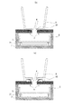
- 7 (a) and 7 (b) are cross-sectional views showing that the FP functions while undergoing elastic deformation in the difference in the shape of the bowl bottom.
- the shape of the bottom of the bowl bottom is various. As shown in FIG. 7 (a), there is a flat bottom of the bowl bottom, and there is a raised bottom as shown in FIG. 7 (b).
- the bowl generally has one drainage hole at the center of the bowl bottom, but the bowl drainage hole has various diameters such as about 10 mm and about 30 mm. Generally, about 10 mm to about 30 mm is common.
- the inner peripheral diameter of the uppermost portion 42 of the packing main body may be larger than the bowl waste water hole 81.
- the inner circumference of the uppermost portion 42 of the packing body functions if it is 30 mm or more, but the inner circumference of the uppermost part 42 of the packing body has a margin from the diameter of the bowl waste water hole. It is desirable to increase it.
- the packing body 41 is crushed and flattened. If the bowl bottom back surface 82 is raised as shown in FIG. 7B, the packing body 41 is flat.
- the main body 41 is only slightly crushed, but in any case, the bottom surface 82 of the bowl bottom places a heavy pressure on the packing body 41, and as a result, is packed around the bowl waste water hole 81.
- the function of FP4 is the same. That is, FP4 can respond to the height of the bowl bottom.
- FIG. 8A is a perspective view showing a state in which the ring-shaped protrusion 5 is provided on the back surface of the top plate and surrounding the top plate hole
- FIG. 8B is a cross-sectional view thereof.
- FIG. 8 omits the illustration below the top plate in order to clarify the positional relationship of the ring-shaped protrusions.
- the vertical relationship in FIG. 8 is clarified.
- the side in contact with the back surface of the top plate is the upper side
- the tip end side of the projection is the lower side.
- the ring-shaped protrusion 5 is provided on the top plate 22 on the top plate rear surface 24 and surrounding the top plate hole 25. Further, as shown in FIG. 8B, the tip is tapered from the upper protrusion root 53 toward the lower protrusion tip 52. As a result, the waste water can be effectively washed away from the form in which the protrusion tip is not thin.
- the effective material of the ring-shaped protrusion 5 can be various materials, but the main point is that it is waterproof.
- the material itself, such as plastic, is waterproof, or wood is waterproofed and attached.
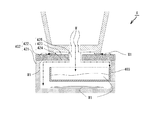
- FIG. 9 is a cross-sectional view showing the flow of wastewater W in the present embodiment.
- FIG. 15 shows how the problems of the prior art shown in FIG. 14 are solved.
- An alternate long and two short dashes line indicates the flow of the waste water W that has come out of the pot.
- FIG. 9 is a view at the time when the water receiving / drawing 3 is about to be pulled out, and illustrates the operation of the auxiliary water receiving tray 7 serving as an auxiliary water receiving when the water receiving / drawing 3 does not exist.
- the waste water from the pot waste water hole 81 tends to flow in various directions, and some waste water tends to come out on the top plate surface 23, but the FP 4 has the waste water to the top plate surface 23. This prevents the course of flow and allows the waste water to flow into the top plate hole 25.
- the ring-shaped protrusion 5 travels down the course of the wastewater. It is possible to flow down into the water receiving / drawing drawer 3 located directly below the top plate hole and the ring-shaped protrusion 5.
- An auxiliary water receiving tray provided below the water receiving drawer 3 when waste water accumulates in the water receiving drawer 3 and the water receiving drawer 3 is taken out from the water receiving body 2 to treat the waste water. Since 7 serves as a temporary water receiver, the waste water can be retained inside the water receiver main body 2 even without the water receiver / drawer 3. Further, the auxiliary water receiving tray is always provided in the water receiving body 2, and it is not necessary to prepare another water receiving device when the water receiving drawer 3 is pulled out.
- the waterproof case 6 since the waterproof case 6 is housed inside the water receiver main body 2, when impact or vibration caused by an accident is applied to the water receiver main body 2, water jumps out of the water receiver / drawer 3. However, at that time, the waterproof case 6 can keep waste water inside the water receiving body 2.
- the second embodiment is obtained by changing the form of the FP in the bowl base with a water receiving function of the first embodiment. Since other structures are the same as those in the first embodiment, the description is incorporated and the corresponding numbers are assumed to be in the 100s.
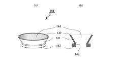
- FIG. 10A is a perspective view showing a form of the FP of the second embodiment
- FIG. 10B is a cross-sectional view thereof.
- the thickness of the packing base 143 of the FP 104 is greater than the thickness of the packing body 141.
- the inner wall 145 of the packing hole Increases the effect of preventing warping.
- FIG. 11 is a perspective view showing a state where the FP shown in FIG. 10 is installed on the top plate 122 of the water receiving body.
- the illustration below the top plate is omitted.
- the shape of the hole periphery groove 126 of the top plate 122 corresponds to the shape of the packing base 143.
- the groove 126 becomes deeper than the case where the thickness of the packing base 143 and the packing body 141 of the FP 104 are the same.
- the third embodiment is a mode in which a packing base back protrusion is provided on the back surface of the FP packing base in the bowl base with a water receiving function of the second embodiment. Since the other structure is common to the second embodiment, the description is incorporated and the corresponding number is set to the 200s.
- FIG. 12A is a perspective view of an FP according to the third embodiment
- FIG. 12B is a cross-sectional view thereof
- FIG. 12C is a perspective view of a state in which the FP is turned upside down. Prior to the description, the vertical relationship in FIG. 12 is clarified. In FIG. 12, the packing body uppermost side of the FP is on the upper side, and the packing base side is on the lower side.
- the packing base back surface 246 surrounds the packing hole 244 and has a hole in the center, and the hole is the packing hole 244 of the FP. And a packing base back protrusion 247 communicating with each other.
- the FP 204 has the packing base back protrusion 247 on the packing base back surface 246.
- the FP provided with the packing base back protrusion 247 is referred to as a protrusion-equipped FP.
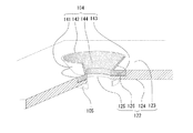
- FIG. 13 is a cross-sectional view showing a state where the top plate is provided with the FP 204 with protrusions.
- the tip of the packing base back projection 247 protrudes below the top plate back surface 224.
- the waste water flows down through the packing hole 244 and the hole of the packing base back projection 247, but the waste water does not flow to the top plate back surface 224.
- the ring-shaped protrusion provided in the form is not necessarily required.
- the fourth embodiment is a pot with a water receiving function according to the first embodiment.
- the same position where the ring-shaped protrusion 5 is provided that is, the top plate back surface 324, and In this embodiment, an annular groove surrounding the top plate hole 325 is provided. Since other structures are the same as those in the first embodiment, the description is incorporated and the corresponding numbers are assumed to be in the 300s.
- FIG. 14A is a perspective view of the back surface of the top plate showing the annular groove 354 of the present embodiment
- FIG. 14B is a cross-sectional view thereof.
Landscapes
- Life Sciences & Earth Sciences (AREA)
- Environmental Sciences (AREA)
- Cultivation Receptacles Or Flower-Pots, Or Pots For Seedlings (AREA)
Abstract
La présente invention concerne un support de jardinière capturant l'eau qui est capable de capter les eaux usées sans fuite et qui permet l'élimination facile des eaux usées. Ce support de jardinière capturant l'eau est pourvu : d'un corps capturant l'eau (2) ; et d'un emballage en forme de cône inversé (4) disposé sur la surface du corps capturant l'eau. Le corps capturant l'eau (2) est pourvu : d'un panneau supérieur (22) pour mettre en place une jardinière dessus et qui présente un trou de panneau supérieur (25) ; d'un tiroir capturant l'eau (3) disposé sous le trou de panneau supérieur (25) ; et d'un boîtier (21) dans lequel le tiroir capturant l'eau (3) est contenu. L'emballage en forme de cône inversé (4) comprend : un corps d'emballage en forme de cône inversé (41) pour la capture des eaux usées de la jardinière et l'évacuation des eaux usées vers le bas à travers un trou d'emballage (44) ; et une base d'emballage (43) s'étendant vers l'extérieur depuis la face externe de la paroi périphérique à l'extrémité inférieure du corps d'emballage (41). Le trou de panneau supérieur (25) et le trou d'emballage (44) communiquent l'un avec l'autre. Le corps d'emballage (41) est élastiquement déformé par le poids de la jardinière placée sur la partie supérieure du corps d'emballage.
Applications Claiming Priority (2)
| Application Number | Priority Date | Filing Date | Title |
|---|---|---|---|
| JP2017-080467 | 2017-04-14 | ||
| JP2017080467A JP6187842B1 (ja) | 2017-04-14 | 2017-04-14 | 水受け機能付き鉢台 |
Publications (1)
| Publication Number | Publication Date |
|---|---|
| WO2018190045A1 true WO2018190045A1 (fr) | 2018-10-18 |
Family
ID=59720504
Family Applications (1)
| Application Number | Title | Priority Date | Filing Date |
|---|---|---|---|
| PCT/JP2018/009044 Ceased WO2018190045A1 (fr) | 2017-04-14 | 2018-03-08 | Support de jardinière capturant l'eau |
Country Status (2)
| Country | Link |
|---|---|
| JP (1) | JP6187842B1 (fr) |
| WO (1) | WO2018190045A1 (fr) |
Cited By (3)
| Publication number | Priority date | Publication date | Assignee | Title |
|---|---|---|---|---|
| US11793123B2 (en) | 2018-11-27 | 2023-10-24 | Cotte Co., Ltd. | Pot stand |
| WO2024011277A1 (fr) * | 2022-07-12 | 2024-01-18 | PerkyPod PTY LTD | Pot pour une plante |
| US11930748B2 (en) | 2019-04-04 | 2024-03-19 | Cotte Co., Ltd. | Receiving tray for pot stand |
Families Citing this family (3)
| Publication number | Priority date | Publication date | Assignee | Title |
|---|---|---|---|---|
| JP6701474B1 (ja) * | 2018-11-27 | 2020-05-27 | 株式会社コッテ | 鉢受台 |
| US12022784B2 (en) | 2021-04-19 | 2024-07-02 | Kristopher John Kalkowski | Plant pot with removable basin |
| US12543659B2 (en) | 2021-04-19 | 2026-02-10 | Drain Drawer Pots, Inc. | Plant pot with removable basin |
Citations (3)
| Publication number | Priority date | Publication date | Assignee | Title |
|---|---|---|---|---|
| JPH0374233U (fr) * | 1989-11-24 | 1991-07-25 | ||
| JP3066935U (ja) * | 1999-08-26 | 2000-03-07 | 明任 木村 | 観葉植物の器状の受け皿と、引き出し |
| US20080083163A1 (en) * | 2006-10-10 | 2008-04-10 | Ofir Amsellem | Flowerpot Saucer Apparatus |
-
2017
- 2017-04-14 JP JP2017080467A patent/JP6187842B1/ja not_active Expired - Fee Related
-
2018
- 2018-03-08 WO PCT/JP2018/009044 patent/WO2018190045A1/fr not_active Ceased
Patent Citations (3)
| Publication number | Priority date | Publication date | Assignee | Title |
|---|---|---|---|---|
| JPH0374233U (fr) * | 1989-11-24 | 1991-07-25 | ||
| JP3066935U (ja) * | 1999-08-26 | 2000-03-07 | 明任 木村 | 観葉植物の器状の受け皿と、引き出し |
| US20080083163A1 (en) * | 2006-10-10 | 2008-04-10 | Ofir Amsellem | Flowerpot Saucer Apparatus |
Cited By (3)
| Publication number | Priority date | Publication date | Assignee | Title |
|---|---|---|---|---|
| US11793123B2 (en) | 2018-11-27 | 2023-10-24 | Cotte Co., Ltd. | Pot stand |
| US11930748B2 (en) | 2019-04-04 | 2024-03-19 | Cotte Co., Ltd. | Receiving tray for pot stand |
| WO2024011277A1 (fr) * | 2022-07-12 | 2024-01-18 | PerkyPod PTY LTD | Pot pour une plante |
Also Published As
| Publication number | Publication date |
|---|---|
| JP6187842B1 (ja) | 2017-08-30 |
| JP2018174820A (ja) | 2018-11-15 |
Similar Documents
| Publication | Publication Date | Title |
|---|---|---|
| JP6187842B1 (ja) | 水受け機能付き鉢台 | |
| US4023305A (en) | Device to remove excess water from plant containers | |
| US5819469A (en) | Support plate for flower-pots that prevents overflow and inhibits mosquito propagation | |
| JP3199670U (ja) | 茶漉し | |
| US3081912A (en) | Combination pouring spout and strainer | |
| TWM480981U (zh) | 肥皂容器 | |
| US11246268B2 (en) | Potted plant tray | |
| JP2015214809A (ja) | ヘアキャッチャー | |
| US964196A (en) | Flower-pot. | |
| US20040107489A1 (en) | Sink drainer system | |
| US3449775A (en) | Kitchen sink plug | |
| JP2019019509A (ja) | ヘアキャッチャー | |
| KR102779295B1 (ko) | 착탈식 물받이판이 구비된 화분 | |
| KR102284144B1 (ko) | 배수 트랩 | |
| JP6847479B2 (ja) | 排水口用ヘアキャッチャー | |
| JP3250364U (ja) | ゴミ捕捉部材保持具に使用される蓋およびこれを有する排水口ゴミ捕捉装置 | |
| JP2014190015A (ja) | ヘアキャッチャー | |
| JP2006314757A (ja) | 水切り容器 | |
| CN212591509U (zh) | 茶盘组结构 | |
| JP6691282B2 (ja) | 排水口用ヘアキャッチャー | |
| JP3012509U (ja) | 植木鉢 | |
| JPH0242786Y2 (fr) | ||
| RU1795013C (ru) | Вставка дл улавливани мусора в сливных устройствах раковин | |
| JP3105054U (ja) | 植木鉢用根ぐされ防止用受け皿 | |
| JP6424306B1 (ja) | 蒸発皿の使用方法 |
Legal Events
| Date | Code | Title | Description |
|---|---|---|---|
| 121 | Ep: the epo has been informed by wipo that ep was designated in this application |
Ref document number: 18785225 Country of ref document: EP Kind code of ref document: A1 |
|
| NENP | Non-entry into the national phase |
Ref country code: DE |
|
| 122 | Ep: pct application non-entry in european phase |
Ref document number: 18785225 Country of ref document: EP Kind code of ref document: A1 |
|
| NENP | Non-entry into the national phase |
Ref country code: JP |