WO2018190094A1 - リアワイパ装置、リアワイパ装置の取付構造、及び、車両のバックドア - Google Patents
リアワイパ装置、リアワイパ装置の取付構造、及び、車両のバックドア Download PDFInfo
- Publication number
- WO2018190094A1 WO2018190094A1 PCT/JP2018/011263 JP2018011263W WO2018190094A1 WO 2018190094 A1 WO2018190094 A1 WO 2018190094A1 JP 2018011263 W JP2018011263 W JP 2018011263W WO 2018190094 A1 WO2018190094 A1 WO 2018190094A1
- Authority
- WO
- WIPO (PCT)
- Prior art keywords
- rear wiper
- output shaft
- mounting
- bracket
- motor
- Prior art date
- Legal status (The legal status is an assumption and is not a legal conclusion. Google has not performed a legal analysis and makes no representation as to the accuracy of the status listed.)
- Ceased
Links
Images


Classifications
-
- B—PERFORMING OPERATIONS; TRANSPORTING
- B60—VEHICLES IN GENERAL
- B60S—SERVICING, CLEANING, REPAIRING, SUPPORTING, LIFTING, OR MANOEUVRING OF VEHICLES, NOT OTHERWISE PROVIDED FOR
- B60S1/00—Cleaning of vehicles
- B60S1/02—Cleaning windscreens, windows or optical devices
- B60S1/56—Cleaning windscreens, windows or optical devices specially adapted for cleaning other parts or devices than front windows or windscreens
- B60S1/58—Cleaning windscreens, windows or optical devices specially adapted for cleaning other parts or devices than front windows or windscreens for rear windows
Definitions
- This disclosure relates to a rear wiper device for wiping a rear window of a vehicle, a mounting structure for the rear wiper device, and a back door of the vehicle.
- a rear wiper device is attached to the back door for opening and closing the luggage compartment behind the vehicle in a wagon car or hatchback car in order to wipe off the rear glass.
- a wiper motor that drives a wiper arm having a wiper blade attached to the tip is attached to an inner panel of a vehicle body by a metal bracket.
- the pivot shaft connected to the wiper arm is inserted through an insertion hole provided in the rear glass.
- Patent Document 1 three mounting legs are provided on a bracket for mounting a wiper motor for driving a wiper arm of a rear wiper device to an inner panel, and each mounting leg is mounted on the inner panel, thereby mounting the wiper motor on the inner panel.
- each mounting leg is mounted on the inner panel, thereby mounting the wiper motor on the inner panel.
- Patent Document 2 discloses the center of gravity of the motor and the arrangement of the mounting legs.
- Patent document 3 is disclosing about the inner cover which covers a housing opening part.
- JP 2009-298381 A US Patent Application Publication No. 2007/0226939 Japanese Patent No. 5350938
- the disclosed object is to reduce the weight of the bracket and save space, and to share the connection structure of the bracket to the inner panel.
- Another object disclosed is to provide a mounting structure for a rear wiper device for mounting the rear wiper device.
- Another object disclosed is to provide a back door with a rear wiper device attached.
- a rear wiper device is a rear wiper device including a wiper motor mounted on a vehicle inner panel by a bracket.
- the wiper motor includes a housing, a motor main body fastened to the housing, and a motor main body.
- a reduction mechanism that decelerates rotation of the rotation shaft, and an output shaft that outputs rotation reduced by the reduction mechanism.
- a wiper body that wipes the windshield is connected to the output shaft, and the bracket is a first mounting leg.
- the two mounting legs different from the first mounting legs are fixed to the inner panel by a plurality of mounting legs, and the two mounting legs are the first mounting legs in a plan view and a fixed posture to the inner panel.
- the first mounting leg includes an axis (L3) of the motor body, a straight line (L9) drawn parallel to the axis of the motor body passing through the upper end of the housing, and the motor A straight line (L7) drawn perpendicularly to the axis of the motor body from the bottom surface of the yoke of the body and a line perpendicular to the axis of the motor body passing through the end of one mounting leg provided on the other side of the perpendicular. It is located in the area
- the first mounting leg is on the output shaft side with respect to the other mounting legs, is above the center of gravity of the wiper motor, and has a speed reduction mechanism and an axial view of the output shaft.
- the two mounting legs among the other mounting legs sandwich the motor body as viewed in the axial direction of the output shaft, or at least one of the two mounting legs sandwiches the motor body
- the intersection of the straight line connecting the two mounting legs in a plan view and the perpendicular drawn from the center of gravity of the wiper motor with respect to the straight line is located on the opposite side of the first mounting leg from the position. It arrange
- the rear wiper device of one embodiment is characterized in that the center of gravity of the wiper motor is arranged inside a triangle connecting the first mounting leg and the two mounting legs in a plan view.
- the distance between the center of gravity of the wiper motor and the center of gravity of the triangle in plan view is 1 of the length of the middle line drawn from the first mounting leg toward the side connecting the two mounting legs. It is characterized by being set smaller than the length of / 3.
- the first mounting leg in a plan view includes an axis of the motor body, a straight line drawn parallel to the axis of the motor body from the axis of the output shaft, and the bottom surface of the yoke of the motor body. Is located in a region surrounded by a straight line drawn perpendicularly to the axis of the motor body and a straight line drawn perpendicularly to the axis of the motor body from the axis of the output shaft.
- the first mounting leg in a plan view includes an axis of the motor main body, a straight line drawn parallel to the axis of the motor main body from the axis of the output shaft, and the axis of the output shaft from the motor.
- the rear wiper device of one embodiment is characterized in that a straight line connecting the two mounting legs in a plan view is substantially parallel to the side of the bracket.
- the rear wiper device is characterized in that the housing has a bottomed box shape and the bracket covers the opening side of the housing.
- the rear wiper device is characterized in that an inner cover is provided between the housing and the bracket on the opening side of the housing.
- the rear wiper device of one embodiment is characterized in that the wiper motor is attached to the mounting surface side of the bracket to the inner panel, and the output shaft protrudes to the inner panel side.
- the rear wiper device of one embodiment is characterized in that the wiper motor is attached to a surface of the bracket opposite to the attachment surface to the inner panel, and the output shaft protrudes toward the inner panel.
- the rear wiper device of one embodiment is characterized in that the output shaft is held by a shaft holding portion, and the shaft holding portion is formed separately from the bracket.
- the rear wiper device of one embodiment is characterized in that the output shaft is held by the shaft holding portion, and the shaft holding portion is formed integrally with the bracket.
- the wiper motor is attached to a surface opposite to the mounting surface of the bracket to the inner panel, the output shaft projects to the inner panel side, and the output shaft is held by the shaft holding portion.
- the shaft holding portion is formed separately from the bracket, and the shaft holding portion is formed integrally with the inner cover.
- the rear wiper device is characterized in that the mounting leg is set at a predetermined inclination angle with respect to the bracket plane.
- the rear wiper device is characterized in that the first mounting leg is located in the protruding direction of the output shaft from the plane of the bracket when the motor body is viewed in the axial direction.
- the first mounting leg has a distance from the center of the first mounting leg to a straight line drawn perpendicularly from the output shaft with respect to the axis of the motor body. It is characterized in that it is arranged at a position (R1 ⁇ R2, R1 ⁇ R3) that is shorter than the distance from the center of each of the two mounting legs to a straight line drawn perpendicularly from the output shaft to the axis of the motor body. .
- the first mounting leg has the axis of the output shaft from the center of the first mounting leg based on the distance from the center of the first mounting leg to the axis of the motor body.
- the distance to the straight line drawn parallel to the axis of the motor body that passes through is shortened (R1 ⁇ R4), and perpendicular to the axis of the motor body that passes through the bottom surface of the yoke of the motor body from the center of the first mounting leg.
- the distance from the center of the first mounting leg to the straight line drawn perpendicularly to the axis of the motor body passing through the axis of the output shaft is shorter (R5 ⁇ R6) than the distance to the straight line drawn in It is characterized by.
- the mounting structure of one embodiment is characterized in that the first mounting leg of the rear wiper device is fixed to the inner panel while avoiding a joint portion with an outer panel provided on the inner panel.
- a vehicle back door includes the rear wiper device or a mounting structure for the rear wiper device.
- the first mounting leg can be arranged around the output shaft, and the length of the mounting leg and consequently the area of the bracket can be reduced. In addition, it is possible to save space. In addition, since the first mounting leg can be fixed to the inner panel with less unevenness or no hole in the lower part of the windshield, the bracket can be shared.
- the load applied to each mounting leg can be equalized.
- the wiper motor can be more stably fixed using the bracket.
- the first mounting leg is appropriately arranged at a position avoiding the speed reduction mechanism and the output shaft.
- the first mounting leg is appropriately arranged at a position avoiding the speed reduction mechanism and the output shaft.
- the length of the mounting leg can be shortened.
- the bracket can also serve as the cover of the housing.
- the opening of the housing can be closed by the inner cover when the wiper motor is transported.
- the output shaft can be arranged in the same direction as the wiper motor.
- the mounting leg can be made shorter.
- the bracket and the shaft holding part can be easily manufactured by forming the shaft holding part separately from the bracket.
- the number of assembling steps can be reduced.
- the shaft holding part and the inner cover are integrally formed, thereby reducing the number of parts and facilitating manufacture.
- the projection angle of the output shaft can be adjusted by appropriately setting the angle of the mounting leg.
- the distance between the first mounting leg and the inner panel can be reduced. As a result, the length of the first mounting leg can be shortened.
- the first mounting leg can be disposed near the output shaft, it is possible to suppress an increase in the size of the bracket.
- the first mounting leg can be disposed near the output shaft, the increase in size of the bracket can be further suppressed.
- the mounting structure of the rear wiper device of one embodiment it is possible to provide the mounting structure of the rear wiper device that has the effects of the rear wiper device and can fix the bracket to an appropriate position of the inner panel.
- the vehicle back door of one embodiment it is possible to provide a vehicle back door that exhibits the effects of the rear wiper device or the mounting structure of the rear wiper device.
- FIG. 1st embodiment It is an external appearance top view of the rear wiper device concerning a 1st embodiment. It is an external appearance side view of FIG. It is an external appearance bottom view of FIG. It is a bottom view of a rear wiper motor. It is sectional drawing of a clutch. It is a fragmentary sectional view of a rear wiper motor. It is a circuit diagram of a rear wiper motor control circuit. It is a partial section perspective view of a back door. It is a perspective view of the fixed part of a back door. It is a perspective view of the back door which attached the rear wiper apparatus. It is a sectional side view at the time of attaching a trim cover. It is a bottom view of the rear wiper device concerning a 2nd embodiment.
- FIG. 1 It is a bottom view of a rear wiper motor. It is a perspective view of a bracket. It is a perspective view of the bracket which concerns on 3rd Embodiment. It is an external appearance top view of the rear wiper apparatus concerning a 4th embodiment. It is an external appearance side view of FIG. It is a partial section perspective view of a back door. It is a perspective view of the fixed part of a back door. It is a partial section perspective view of the back door which attached the rear wiper device. It is a sectional side view at the time of attaching a trim cover. It is an external appearance top view of the rear wiper apparatus concerning a 5th embodiment. It is an external appearance side view of FIG. It is a partial section perspective view of a back door.
- FIG. 1 It is a perspective view of the fixed part of a back door. It is a perspective view of the back door which attached the rear wiper apparatus. It is a sectional side view at the time of attaching a trim cover. It is an external appearance top view of the rear wiper apparatus concerning a 6th embodiment. It is an external appearance side view of FIG. It is a partial section perspective view of a back door. It is a perspective view of the fixed part of a back door. It is a perspective view of the back door which attached the rear wiper apparatus. It is a sectional side view at the time of attaching a trim cover. It is an external appearance top view of the rear wiper apparatus concerning a 7th embodiment. It is an external appearance side view of FIG. It is a perspective view of a bracket.
- FIG. 37 is a side view of FIG. 36. It is a partial section perspective view of a back door. It is a perspective view of the fixed part of a back door. It is a perspective view of the back door which attached the rear wiper apparatus. It is a sectional side view at the time of attaching a trim cover.
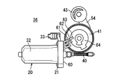
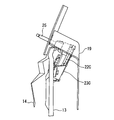
- FIGS. 1 is an external plan view of the rear wiper device 1 according to the first embodiment
- FIG. 2 is an external side view of FIG. 1
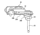
- FIG. 3 is an external bottom view of FIG. 1
- FIG. 4 is a rear wiper motor.
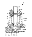
- FIG. 5 is a cross-sectional view of the clutch 43.
- the rear wiper device 1 is attached to the inner panel 13 of the vehicle back door 10 and wipes the windshield 11 of the back door 10 with the wiper body 4 connected to the output shaft 25.
- the wiper body 4 includes a wiper arm 2 and a wiper blade 3 connected to the wiper arm 2, and one end of the wiper arm 2 is connected to an output shaft 25. Then, the output shaft 25 is driven to rotate forward and backward by a rear wiper motor 36 as a wiper motor, and the wiper arm 2 is oscillated by the output shaft 25, whereby the wiper blade 3 is moved upward and downward from the windshield 11 surface.
- the wiper body 4 is configured so as to be wiped back and forth between the reverse positions.
- the rear wiper device 1 includes a rear wiper motor 36 and a bracket 23.
- the rear wiper motor 36 includes a motor body 20 and a gear part 35.
- the motor body 20 is composed of, for example, a DC brush motor.
- the motor main body 20 includes a stator including a yoke 32 as a housing of the motor main body 20 and a rotor (not shown) that is concentric with the stator and rotatably supported inside the stator.
- the yoke 32 is formed in a substantially bottomed cylindrical shape made of a magnetic material such as iron, and a four-pole permanent magnet (not shown) is arranged in the circumferential direction on the inner peripheral side of the cylindrical portion of the yoke 32. It is provided to be arranged alternately.
- a round bar-shaped rotation shaft is provided coaxially with the bottomed cylindrical yoke 32.
- a bearing is provided on the non-opening side (bottom side) of the yoke 32, and rotatably supports one end (the right side in FIG. 4) of the rotating shaft.
- a worm 40 described later is provided on the other end side of the rotating shaft.
- a flange 21 is provided that protrudes outward from the opening end of the yoke 32 in the direction orthogonal to the axis of the rotation axis.
- the rotor is provided with an armature so as to face the inner peripheral surface of the permanent magnet.
- the armature has a plurality of magnetic poles around which a coil is wound, and each magnetic pole faces the permanent magnet.
- a commutator that is electrically connected to the coil is provided on the opening side of the yoke 32 of the rotor, and a plurality of brushes supported by a brush holder (see FIG. 6) are in sliding contact with the commutator, thereby energizing the coil. It is the composition to do.
- the brush is electrically connected to the connector 33, and is supplied with electric power from an external power source (not shown) connected to the connector 33.
- the motor body 20 is described as a brush motor as a DC motor.
- the motor type of the motor body 20 is not limited to this, and any type of motor such as a brushless motor, for example. But it can be applied.
- the motor main body 20 is described as a one-way rotation type motor, but the present invention is not limited to this, and the disclosure includes, for example, a motor capable of forward and reverse rotation. When using a motor that can rotate forward and reverse, the swing mechanism can be omitted.
- the gear portion 35 is provided in the bottomed box-shaped metal housing 22, and the worm 40 connected to the rotating shaft of the motor body 20, the worm wheel 41 meshed with the worm 40, and the speed reduction connection of the worm wheel 41.
- An oscillating rod 42 coupled to the shaft 41a, a clutch 43 including a first coupling plate meshed with a sector gear 42b of the oscillating rod 42, an output shaft 25 connected to the output of the clutch 43, and an output shaft 25;
- a shaft holding portion 24 that covers the periphery of the clutch 43 is provided.
- the housing 22 is formed by die-casting aluminum or an aluminum alloy, for example.
- the shaft holding portion 24 is formed of, for example, an iron plate, and a cylindrical portion 24 c that protrudes in a cylindrical shape on the output shaft 25 side is provided around the output shaft 25 and the clutch 43.
- a shaft support portion 24a provided with a bearing 55 that supports the output shaft 25 is formed on the distal end side of the cylindrical portion 24c.
- the output shaft 25 is inserted through the shaft support portion 24a.
- a guide member 56 is provided on the inner periphery of the base end side of the cylindrical protrusion, and supports the outer periphery of the output shaft 25 protruding side of the first engagement plate 50 described later.
- a flat plate portion 24 b facing the opening of the housing 22 is provided on the outer periphery of the base end portion side of the cylindrical projecting portion of the shaft holding portion 24.
- the flat plate portion 24 b faces the opening of the housing 22 so as to cover the periphery of the output shaft 25 and the clutch 43 and a part of the worm wheel 41 from the short side (the upper side in FIG. 4) of the housing 22 on the output shaft 25 side. Then, it is screwed together with the bracket 23 by a plurality of male screws 48.
- the flat plate part 24b is provided so that a part of opening of the housing 22 may be covered, this embodiment does not limit the range which covers the opening of the housing 22, The range in which the flat plate portion 24b covers the opening of the housing 22 can be changed according to the size and shape of each portion.
- the housing 22 is integrally formed with a gear accommodating portion 45 that accommodates the gear portion 35 and a flange connecting portion 46 that connects the flange 21 of the motor body 20.
- the flange connecting portion 46 has a shape corresponding to the outer shape of the flange 21, and the flange connecting portion 46 and the flange 21 are fastened and fixed by screws or the like.
- a gear housing portion 45 is formed integrally with the flange connecting portion 46 on the opposite side of the flange 21 mounting surface.
- the gear housing portion 45 is formed in a bottomed box shape that opens in one of the radial directions of the rotating shaft of the motor body 20 and in the protruding direction of the output shaft 25, and houses the gear portion 35.
- a plurality of female screws 47 are provided at the edge of the gear housing portion 45, and the shaft holding portion 24 and the bracket 23 are fastened to the female screws 47 around the output shaft 25 by male screws 48.
- the bracket 23 is fastened and fixed to the other female screw 47 by a male screw 48.
- the gear housing portion 45 has a substantially rectangular shape with the worm 40 housing portion as a short side on one side and a long side perpendicular to the axis of the worm 40 as viewed from the output shaft 25 side (the left and right directions in FIG. 4 are short sides).
- the rectangular shape has a long side in the vertical direction.
- a worm 40 is formed by rolling or the like on the other end side (left side in FIG. 4) of the rotation shaft of the motor body 20. The other end of the rotating shaft including the worm 40 enters the gear housing 45, and both ends of the worm 40 are pivotally supported by bearings.
- a worm wheel 41 made of, for example, a resin material and having a disk shape is disposed on the side of the worm 40 in the gear housing portion 45 (above the paper surface in FIG. 4).
- the worm wheel 41 is rotatably supported around an axis whose axial direction is the opening direction of the housing 22 and the opposite direction thereof while being engaged with the worm 40.
- the worm 40 and the worm wheel 41 constitute a speed reduction mechanism.
- An insertion hole (a metal speed reduction connecting shaft 41a is inserted into a surface of the worm wheel 41 in the opening direction of the housing 22 so as to be rotatable at a position shifted from the rotation center to the outer peripheral side (radially outward) without rattling. (Not shown) is provided.
- a sector gear that meshes with a gear tooth 50 a provided on the outer periphery of the first engagement plate 50 constituting the clutch 43 on the side surface on the output shaft 25 side on the other end side (the upper side in the drawing of FIG. 4) of the swing rod 42. 42b is provided.
- the clutch 43 is located on the opposite side of the worm 40 with the worm wheel 41 of the gear housing 45 interposed therebetween, and is provided near the motor main body 20 in the short side direction of the gear housing 45. On the side opposite to the motor body 20 of the clutch 43, a space is provided so that the sector gear 42b side (the upper side in the drawing in FIG. 4) of the swing rod 42 can swing.
- the clutch 43 can be rotated integrally by engaging with the first engagement plate 50 in which the output shaft 25 is rotatably inserted into the center insertion hole 50b, and can be rotated integrally with the first engagement plate, and can be released from the uneven engagement.
- the output shaft 25 which rotates integrally with the engagement plate 51 and the control plate 52 is provided.
- the outer periphery on the protruding side of the output shaft 25 in the axial direction of the first engagement plate 50 is supported by a guide member 56, and the outer periphery on the opposite side of the output shaft 25 in the axial direction of the first engaging plate 50.
- the end surface on the protruding side of the output shaft 25 in the axial direction of the first engagement plate 50 is provided with an uneven surface that repeats unevenness in the circumferential direction that engages with the second engagement plate 51.
- An uneven surface corresponding to the shape of the uneven surface of the first engagement plate is provided on the end surface of the second engagement plate 51 on the opposite side of the output shaft 25 in the axial direction.
- the restriction plate 52 is provided with a restriction convex portion 52a in order to prevent the output shaft 25 from rotating more than a predetermined angle.
- the restricting convex portion 52 a restricts the rotation range of the output shaft 25 by engaging with a restricting wall projecting on the inner peripheral side of the shaft holding portion 24 in the circumferential direction.
- a swing coupling shaft projects from the other end of the swing rod 42 (the upper side in FIG. 4) opposite to the output shaft 25 (sector gear 42b) and on the opposite side of the output shaft 25.
- the swing connecting shaft is inserted into a first connecting hole (not shown) provided at one end of the swing lever 54 so as to be relatively rotatable.
- a second connection hole 54b is provided at the other end of the swing lever 54, and an end of the output shaft 25 on the counter-output side (anti-projection side) is inserted into the second connection hole 54b so as to be relatively rotatable. Yes.
- the swing lever 54 keeps the distance between the swing connecting shaft and the output shaft 25 constant so that the sector gear 42b of the swing rod 42 and the gear teeth 50a of the first engagement plate 50 are engaged with each other. It can be stabilized.
- the swing rod 42 and the swing lever 54 constitute a swing mechanism that converts the rotational motion of the motor body 20 decelerated by the speed reduction mechanism into the reciprocating rotational motion of the output shaft 25.
- the gear unit 35 includes a speed reduction mechanism (worm 40 and worm wheel 41), a swing mechanism (swing rod 42 and swing lever 54), and a clutch 43.
- the gear part 35 which is not provided with the clutch 43
- a gear tooth provided at the base end portion of the output shaft 25 and rotating integrally with the output shaft 25 meshes with the sector gear 42b, and the output shaft 25 rotates forward and backward by swinging of the sector gear 42b.
- FIG. 6 is a partial sectional view of the rear wiper motor 36
- FIG. 7 is a circuit diagram of the rear wiper motor control circuit 71.
- a conductive plate 64 having a predetermined pattern is provided on the surface of the worm wheel 41 on the side opposite to the output shaft 25.
- the brush holder 60 is provided with a first contact plate 61, a second contact plate 62 and a third contact plate 63 so as to be in sliding contact with the conductive plate 64, and a wiring formed of a conductive metal plate (not shown).
- a circuit as shown in FIG. 7 is configured.
- the intermittent drive circuit 69 including the intermittent operation circuit 67 and the switching element S is provided integrally with the brush holder 60 is shown, but the disclosure is not limited to this, for example, The intermittent drive circuit 69 is also provided outside the rear wiper motor 36 as a separate body.
- the change-over switch 68 has a stop position P1 for stopping the motor body 20, a normal operation position P2 for continuously operating the motor body 20, and an intermittent operation of the motor body 20 with a predetermined pause time. Can be switched to the intermittent operation position P3.
- the predetermined pause time at the intermittent operation position P3 may be variably settable.
- the intermittent operation circuit 67 turns on the switching element S for a certain period at regular time intervals. Since the current flows from the positive electrode of the battery E to the ground through the relay 66, the diode B, the switching element S, and the changeover switch 68 while the switching element S is on, the contact of the relay 66 is switched to a.
- the contact of the relay 66 is switched to a, regardless of the positional relationship between the first to third contact plates 61 to 63 and the conductive plate 64, the relay contact a, relay contact c, choke coil 65, Since a current flows to the ground through the motor body 20 and the breaker 70, the motor body 20 is driven.
- the relay 66 since the relay 66 is not excited during the period when the switching element S is off, the relay 66 is switched from the relay contact a to the relay contact b.
- the period when the second contact plate 62 and the third contact plate 63 are conducted by the conductive plate is changed from the positive electrode of the battery E to the third contact plate 63, the conductive plate 64, Since the current flows to the ground through the second contact plate 62, the relay contact b, the relay contact c, the choke coil 65, the motor main body 20, and the breaker 70, the motor main body is driven.
- the wiper arm 2 stops at the lower reverse position.
- the switch 68 is switched from the intermittent operation position P3 to the stop position P1 when the switching element S is off, the relay 66 is not excited and the contact of the relay 66 is switched to b. It remains stopped.
- the changeover switch 68 is switched from the intermittent operation position P3 to the stop position P1 when the switching element S is on, the operation is the same as when the switching element S is off, and the wiper arm 2 is in the lower inversion position. Stop at.
- Bracket 23 made of, for example, an iron plate is provided on the opening side of the housing 22.
- the bracket 23 is fixed to a plurality of female screws 47 provided at the edge of the gear housing portion 45 of the housing 22 by a male screw 48 around the output shaft 25 together with the shaft holding portion 24.
- the bracket 23 has a substantially triangular plate shape when viewed from the axial direction of the output shaft 25.
- a clutch insertion hole 39 which will be described later, is provided in the vicinity of the upper apex, and three attachment legs 26 are provided in the vicinity of the lower two apexes.
- the lower two second mounting legs 27 and the third mounting legs 28 are provided in .about.28.
- the first to third mounting legs 26 to 28 are substantially defined with the first mounting leg as an upper apex and the second mounting leg 27 and the third mounting leg 28 as two apexes as viewed from the axial direction of the output shaft 25. They are arranged to form an isosceles triangle.
- a straight line connecting the second mounting leg 27 and the third mounting leg 28 is substantially parallel to the bottom side of the bracket 23 that is substantially parallel to the axial direction of the motor body 20.
- each of the mounting legs 26 to 28 is provided in the bracket 23 at a position of a dead space where the rear wiper motor 36 is not disposed, and at a position close to the rear wiper motor 36.
- the first mounting leg 26 is provided above the bracket 23 and at a position that avoids the output shaft 25 (a position that does not overlap the output shaft 25 when viewed from the output shaft 25 direction).
- the first mounting leg 26 is viewed from the direction of the output shaft 25 (in plan view), the axis L3 of the motor main body 20, a straight line L9 parallel to the axis L3 of the motor main body 20 passing through the upper end of the housing 22, It is provided in a region (rectangular inside) surrounded by a perpendicular line L6 from the axis L4 of the output shaft 25 to the axis line L3 of the motor body 20 and a perpendicular line L7 from the bottom surface 32a of the yoke 32 to the axis line L3 of the motor body 20.
- the upper end of the housing 22 is the upper end in FIG.
- the upper end of the housing 22 is an end portion of the housing 22 on the side where the output shaft 25 is positioned with respect to the axis L3 of the motor body 20. More specifically, the first mounting leg 26 is seen from the direction of the output shaft 25, the axis L3 of the motor body 20, the straight line L5 passing through the axis L4 of the output shaft 25 and parallel to the axis L4 of the motor body 20, and the flange 21. To the axis L3 with respect to the axis L3 of the motor main body 20 and the area surrounded by the vertical line L7 with respect to the axis L3 of the motor main body 20 from the bottom of the yoke 32 (inside the rectangle).
- the first mounting leg 26 has a shortest distance R1 from the center of the first mounting leg 26 to the perpendicular L6 (the length of the perpendicular to the perpendicular L6 from the center of the first mounting portion 26). It is provided at a position (R1 ⁇ R2 or R1 ⁇ R3) that is shorter than the shortest distance R2 from the vertical line L6 to the center of the second mounting leg 27 or the shortest distance R3 from the vertical line L6 to the center of the third mounting leg 28.
- the first mounting leg 26 has a shortest distance R5 from the center of the first mounting leg 26 to the straight line L5, from the center of the first mounting leg 26 to the axis L3 of the motor body 20. It becomes shorter than the shortest distance R6 (R5 ⁇ R6), and the shortest distance R1 from the center of the first mounting leg 26 to the perpendicular L6 is shorter than the shortest distance R4 from the center of the first mounting leg 26 to the straight line L7 (R1). ⁇ R4) Provided at the position. For this reason, it is possible to design the size of the bracket 23 small. Since the size of the bracket 23 can be reduced, weight reduction can be realized. Further, each of the mounting legs 26 to 28 can be mounted in a limited space of the inner panel 13 of the back door 10 of the vehicle by using the first mounting leg 26 provided in the upper portion. The shape can be commonly used regardless of the design of the back door 10 of the vehicle.
- the center of gravity G1 of the rear wiper motor 36 viewed from the axial direction of the output shaft 25 is disposed inside the triangle T constituted by the first to third mounting legs 26 to 28.
- the center of gravity G1 of the rear wiper motor 36 viewed from the axial direction of the output shaft 25 is desirably disposed at a position close to the center of gravity G2 of the triangle T constituted by the first to third mounting legs 26 to 28.
- the distance between the center of gravity G1 of the rear wiper motor 36 and the center of gravity G2 of the triangle T is the length of the middle line C drawn from the first mounting leg 26 toward the side connecting the second mounting leg 27 and the third mounting leg 28. It is set smaller than 1/3 of the length.
- the first mounting leg 26 When viewed from the axial direction of the output shaft 25, the first mounting leg 26 is disposed above the other second mounting legs 27 and the third mounting legs 28 and above the center of gravity G 1 of the rear wiper motor 36. ing.
- the second mounting leg 27 and the third mounting leg 28 are disposed at a position sandwiching the motor body 20 in the axial direction of the motor body 20, and the axial direction of the output shaft 25
- the intersection of the straight line L1 connecting the second mounting leg 27 and the third mounting leg 28 and the perpendicular L2 drawn from the center of gravity of the rear wiper motor 36 with respect to the straight line L1 is the second mounting leg 27 and the second mounting leg 27.
- the three mounting legs 28 are arranged so as to be located in the middle. In the axial direction of the motor main body 20, the second mounting legs 27 and the third mounting legs 28 are located on both sides of the motor main body 20.
- the second mounting leg 27 is located in one region partitioned by the perpendicular L6.
- the third attachment leg 28 is located in the other region partitioned by the perpendicular L6.
- an insertion hole 37 (see FIG. 12) for inserting the bolt 29 and the vibration isolating member 31 is provided.
- the insertion hole 37 is provided with a communication hole 38 that communicates with the insertion hole 37 from the outside of the bracket 23.
- the vibration isolation member 31 has a cylindrical shape having flanges on the upper surface and the lower surface.
- the anti-vibration member 31 has a U shape having a corner portion with a rounded cross section viewed from the circumferential direction. The anti-vibration member 31 is inserted from the communication hole 38, and the anti-vibration member 31 is attached so as to sandwich the periphery of the insertion hole 37 of the bracket 23.
- the anti-motor body 20 mounting surface side flange is in contact with the inner panel 13 of the back door 10.
- the bracket 23 is attached to the inner panel 13 of the back door 10 of the vehicle by using a nut or by screwing a bolt 29 into a female screw provided on the inner panel 13 side.
- the mounting legs 26 to 28 are set to be inclined at a predetermined angle in order to adjust the protruding direction of the output shaft 25.
- This predetermined angle is set according to the design of the back door 10 of the vehicle, that is, the shape of the windshield 11 and the inner panel 13.
- the angles of the mounting legs 26 to 28 are set so that the angle difference between the mounting legs 26 to 28 is in the range of 0 degrees to 70 degrees.
- the assembly of the rear wiper motor 36 (rear wiper device 1) to the inner panel 13 can be simplified, and the assembly is easy. Can be improved.
- the output shaft 25 projects so as to be perpendicular to the mounting surface of the rear wiper motor 36 of the bracket 23.
- each bolt 29 is perpendicular to the mounting surface of each mounting leg 26-28.
- the inclination angles of the mounting legs 26 to 28 are set so that the angle of each bolt 29 is substantially equal to the angle of the output shaft 25.
- the inclination angle of each of the mounting legs 26 to 28 is the direction in which the tip of each bolt 27 faces downward by the predetermined angle common to the angle of the output shaft 25.
- the inclination angles of the mounting legs 26 to 28 are set to be substantially the same direction.
- the mounting legs 26 to 28 can be provided close to each other, it is not necessary to change the arrangement of the mounting legs 26 to 28 in accordance with the design of the vehicle, and a slight angle adjustment of the mounting legs 26 to 28 is possible. Only by this, the angle of the output shaft 25 can be adjusted. In addition, since the angle can be adjusted by the fixing portions 16 to 18 provided on the back door 10 side, the change on the bracket 23 side is not necessary or can be completed at a minimum. Can be realized.
- a clutch insertion hole 39 through which the clutch 43 (cylindrical portion 24c of the shaft holding portion 24) is inserted is provided at a position corresponding to the clutch 43 in the bracket 23 when viewed from the axial direction of the output shaft 25. Therefore, the rear wiper motor 36 is attached to the surface opposite to the attachment surface of the bracket 23 to the back door 10.
- the clutch 43 and the output shaft 25 project in the direction of the mounting surface of the bracket 23 to the back door 10 by being inserted into the clutch insertion hole 39. Accordingly, the output shaft 25 is disposed so as to be inserted into the output shaft insertion hole 12 provided in the windshield 11 in a state where the bracket 23 (rear wiper device 1) is attached to the back door 10. Further, since the bracket 23 is provided with the shaft holding portion 24 as a separate body, it is not necessary to form a cylindrical shape in which the clutch 43 and the output shaft 25 are inserted in the bracket 23, and therefore, the manufacture becomes easy.
- the clutch insertion hole 39 can be communicated with the upper part of the bracket 23. That is, the shape and size of the upper portion of the bracket 23 can be changed so that the shaft holding portion 24 is exposed from the upper edge portion of the bracket 23.
- the end face on the output shaft 25 side of the clutch 43 is configured such that the bracket 23 does not exist in part or in whole and the shaft holding portion 24 is exposed. As a result, the size of the bracket 23 can be further reduced.
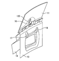
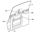
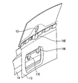
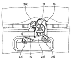
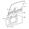
- FIGS. 8 is a partial sectional perspective view of the back door 10
- FIG. 9 is a perspective view of the fixing portions 16 to 18 of the back door 10
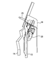
- FIG. 10 is a perspective view of the back door 10 to which the rear wiper device 1 is attached.
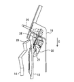
- FIG. 11 is a cross-sectional side view when the trim cover 19 is attached.
- FIG. 11 shows the fixed posture of the rear wiper device to the inner panel.
- the vehicle back door 10 includes an outer panel 14 as an exterior of the vehicle, an inner panel 13 provided inside the outer panel 14 and joined by being partially welded to the outer panel 14, an upper portion of the outer panel 14 and the inner panel 13.
- the windshield 11 is provided.
- the inner panel 13 is a panel disposed on the inner side of the vehicle body from the outer panel 14. Further, when the inner panel 13 and the outer panel 14 are integrally formed as in the case of the resin back door 10, a portion disposed on the inner side of the vehicle body is exposed to the inner panel 13 and the outer side of the vehicle body (so as to be exposed). The portion to be arranged corresponds to the outer panel 14.
- a portion forming the inside of the vehicle body corresponds to the inner panel 13 and a portion forming the outside of the vehicle body corresponds to the outer panel 14.
- An output shaft insertion hole 12 through which the output shaft 25 is inserted is provided substantially at the center near the lower portion of the windshield 11.
- a space between the output shaft 25 and the output shaft insertion hole 12 is sealed with a cylindrical grommet (not shown).
- the inner panel 13 and the outer panel 14 are provided with a plurality of welded portions 15 as joints below the windshield 11, and a first fixing portion 16 is provided at a position avoiding the welded portions 15.
- the joint portion is the welded portion 15 in which the outer panel 14 and the inner panel 13 are welded and joined, but the disclosure is not limited thereto.
- the outer panel 14 and the inner panel 13 may be bonded and bonded together. Moreover, it is good also considering the location which joined the outer panel 14 and the inner panel 13 with the rivet as a junction part.
- the inner panel 13 is provided with an uneven portion and a hole, and the second fixing portion 17 is located at a position avoiding the hole and in the vicinity of the first fixing portion 16 below the first fixing portion 16.
- fixed part 18 is provided.
- the relative positions of the first to third fixing portions 16 to 18 correspond to the arrangement of the first to third mounting legs 26 to 28, respectively.
- a second attachment leg 27 is attached to the second fixing portion 17, and a third attachment leg 28 is attached to the third fixing portion 18.
- the rear wiper motor 36 is a surface opposite to the mounting surface of the bracket 23 to the inner panel 13. Is arranged.
- the output shaft 25 and the clutch 43 protrude into the mounting surface side (inner panel 13 side) of the bracket 23 by being inserted into a clutch insertion hole 39 provided in the bracket 23. Accordingly, the output shaft 25 is disposed so as to be inserted into the output shaft insertion hole 12 provided in the windshield 11.
- the first to third mounting legs 26 to 28 are set so as to be inclined at a predetermined angle with respect to the mounting surface of the rear wiper motor 36 of the bracket 23, so that the output shaft 25 is designed for the windshield 11.
- the bracket 23 can be shared.
- the inner panel 13 and the vehicle interior side of the rear wiper device 1 are covered with a trim cover 19.
- the periphery of the output shaft 25 protrudes above the inner panel 13 (upper side in FIG. 11).
- the trim cover 19 is provided with a portion (see FIGS. 10 and 11) projecting upward around the output shaft 25, and also covers the rear wiper device 1.
- Each of the mounting legs 26 to 28 is provided in the bracket 23 at a position of a dead space where the rear wiper motor 36 is not disposed, and at a position close to the rear wiper motor 36.
- the size of the bracket 23 can be designed to be small.
- the trim cover 19 can be provided close to the rear wiper motor 36 and the inner panel 13, the trim cover 19 can be designed to be small, and the space in the vehicle interior can be widened.
- the rear wiper motor control circuit 71 controls the rotation of the motor body 20 connected to the wiper body 4 via the speed reduction mechanism, the swing mechanism, the clutch 43 and the like according to the changeover switch 68.
- the rotational movement of the motor body 20 decelerated by the speed reduction mechanism is converted into the reciprocating rotational movement of the output shaft 25 by the swing mechanism, and the output shaft 25 is reciprocated and rotated, whereby the wiper arm 2 connected to the output shaft 25 and The wiper blade 3 attached to the tip of the wiper is driven to swing, and the wiper blade 3 wipes the windshield 11 of the vehicle.
- the housing 22 in which the flange 21 of the motor body 20 is fastened and fixed to the flange connecting portion 46 is made of, for example, a material such as aluminum or aluminum alloy, and is formed by, for example, die casting, and the gear housing portion 45 is integrally formed. ing.
- the gear housing portion 45 houses a speed reduction mechanism, a swing mechanism, and a clutch 43.
- the gear housing portion 45 has a substantially rectangular shape with the worm 40 housing portion as the short side on one side and the long side in the direction perpendicular to the axis of the worm 40.
- the periphery of the output shaft 25 and the clutch 43 protrudes in a cylindrical shape on the output shaft 25 side, and a shaft support portion 24a provided with a bearing 55 that supports the output shaft 25 is formed on the tip side, for example, an iron plate. Covered by the formed shaft holding portion 24.
- a flat plate portion 24 b facing the opening of the housing 22 is provided on the outer periphery of the base end portion side of the cylindrical projecting portion of the shaft holding portion 24.
- the flat plate portion 24b is opposed to the opening of the housing 22 so as to cover the periphery of the output shaft 25 and the clutch 43 and a part of the worm wheel 41 from the short side of the housing 22 on the output shaft 25 side. 48 and screwed together with the bracket 23.
- the bracket 23 can be easily formed.
- the flat plate portion 24b of the shaft holding portion 24 is sandwiched between the opening side of the housing 22, the clutch 43 is inserted into the clutch insertion hole 39, and the bracket 23 is screwed.
- the bracket 23 is provided with first to third mounting legs 26 to 28, and bolts are attached to the first to third fixing portions 16 to 18 provided on the inner panel 13 of the back door 10 via vibration-proof members 31. 29, respectively.
- vibration isolation member By providing the vibration isolation member, it is possible to reduce the vibration generated by the rear wiper motor 36 from being transmitted to the back door 10 and to reduce the noise in the vehicle interior.
- unexpected vibration is applied to the rear wiper motor 36 and the rear wiper motor 36 breaks down. It can be prevented from being damaged.
- the rear wiper motor 36 is mounted on the surface of the bracket 23 opposite to the mounting surface of the bracket 23 on the inner panel 13, the distance between the bracket 23 and the inner panel 13 can be reduced. Further, the first to third mounting legs 26 to 28 are provided in positions in a dead space where the rear wiper motor 36 is not disposed and in positions close to the rear wiper motor 36. In particular, since the first mounting leg 26 is provided above the bracket 23 and at a position avoiding the output shaft 25, the size of the bracket 23 can be designed to be small. For this reason, the trim cover 19 can be provided in the vicinity of the rear wiper motor 36 and the inner panel 13, and a space in the vehicle compartment can be increased. Since the size of the bracket 23 can be designed to be small, the weight of the bracket 23 can be reduced.
- first to third mounting legs 26 to 28 can be mounted in a limited space of the inner panel 13 of the vehicle back door 10, the shape of the bracket 23 is common regardless of the design of the vehicle back door 10. Can be used. Further, the first to third fixing portions 16 to 18 are provided at positions avoiding the welded portion 15 (joint portion). However, since the size of the bracket 23 can be reduced, the first to third mounting legs 26 to 28 are provided. The design to arrange is easy.
- the first to third mounting legs 26 to 28 are set to be inclined at a predetermined angle with respect to the mounting surface of the rear wiper motor 36 of the bracket 23, so that the output shaft 25 corresponds to the design of the windshield 11. It is set to be inserted through the output shaft insertion hole 12 at a predetermined angle. Further, the inclination angle of the first to third attachment legs 26 to 28 on the bracket 23 side is adjusted by adjusting the inclination of the attachment surface of the first to third fixing portions 16 to 18 provided on the back door 10 side of the vehicle. Since the adjustment of the inclination angle can be minimized, the bracket 23 can be shared.
- the first mounting leg 26 is provided above the bracket 23 and at a position avoiding the output shaft 25, all the mounting legs 26 to 28 can be arranged on the upper portion of the inner panel 13. Since vibration is generated by the operation of the rear wiper motor 36, when the mounting legs 26 to 28 are arranged in the center of the inner panel 13, noise in the vehicle interior may become a problem. In the first embodiment, however, Since all the mounting legs 26 to 28 can be arranged on the upper portion of the inner panel 13, it is possible to reduce the noise in the vehicle interior caused by the vibration of the rear wiper motor 36.
- the first to third mounting legs 26 to 28 are substantially defined with the first mounting leg as an upper apex and the second mounting leg 27 and the third mounting leg 28 as two apexes as viewed from the axial direction of the output shaft 25. Since they are arranged so as to form an isosceles triangle, the right and left balance is improved with respect to the load applied to the rear wiper motor 36.
- the center of gravity G1 of the rear wiper motor 36 viewed from the axial direction of the output shaft 25 is disposed inside the triangle T constituted by the first to third mounting legs 26 to 28.
- the center of gravity G1 of the rear wiper motor 36 viewed from the axial direction of the output shaft 25 is desirably disposed at a position close to the center of gravity G2 of the triangle T constituted by the first to third mounting legs 26 to 28.
- the distance between the center of gravity G1 of the rear wiper motor 36 and the center of gravity G2 of the triangle T is the length of the middle line C drawn from the first mounting leg 26 toward the side connecting the second mounting leg 27 and the third mounting leg 28. It is set smaller than 1/3 of the length.
- the first mounting leg 26 When viewed from the axial direction of the output shaft 25, the first mounting leg 26 is disposed above the other second mounting legs 27 and the third mounting legs 28 and above the center of gravity G 1 of the rear wiper motor 36. ing.
- the second mounting leg 27 and the third mounting leg 28 are arranged at a position sandwiching the motor body 20 in the axial direction of the motor body 20 and are second when viewed from the axial direction of the output shaft 25 (in plan view).
- An intersection of a straight line L1 connecting the mounting leg 27 and the third mounting leg 28 and a perpendicular line L2 drawn from the center of gravity G1 of the rear wiper motor 36 with respect to the straight line L1 is located between the second mounting leg 27 and the third mounting leg 28.
- the first to third mounting legs 26 to 28 are arranged in consideration of the center of gravity of the rear wiper motor 36, thereby stabilizing the rear wiper motor 36. Can be fixed.
- FIGS. 12 is a bottom view of the rear wiper device 1A according to the second embodiment
- FIG. 13 is a bottom view of the rear wiper motor 36A
- FIG. 14 is a perspective view of the bracket 23A.
- symbol is attached
- the rear wiper device 1A differs from the first embodiment in that the shaft holding portion 24A covers the entire opening of the housing 22A.
- the flat plate portion 24b is formed to have a size that covers the entire opening of the housing 22A.
- a circular flat plate protruding portion 77 that protrudes in the same direction. Is provided.
- a plurality of claw portions 75 extending in the direction opposite to the protruding direction of the output shaft 25 (the direction of the housing 22A) are provided at the edge of the flat plate portion 24b. The tip of the claw portion 75 is divided into two forks and extends in the opening direction.
- the bracket 23A is provided with a convex portion insertion hole 78 through which the flat plate convex portion 77 is inserted.
- a plurality of claw insertion portions 76 into which the claw portions 75 are respectively inserted are provided at positions corresponding to the plurality of claw portions 75 at the edge portion of the housing 22A.
- the shaft holding portion 24A and the bracket 23A are temporarily fixed to the housing 22 by inserting the claw portion 75 of the shaft holding portion 24A into the claw insertion portion 76.
- the bracket 23A is overlapped so that the temporarily fixed shaft holding portion 24A is sandwiched between the housing 22A, and the male screw 47 is passed through the screw holes of the shaft holding portion 24A and the bracket 23A to the female screw 47 of the housing 22A. Screw together.
- the rear wiper motor 36A By inserting the claw portion 75 into the claw insertion portion 76, the rear wiper motor 36A can be transported with the shaft holding portion 24A temporarily fixed to the housing 22A so as to cover the entire opening of the housing 22A. Since the entire opening of the housing 22A is covered with the shaft holding portion 24A, it is possible to prevent foreign matter from entering the rear wiper motor 36A during transportation. In addition, simply by inserting the claw portion 75 into the claw insertion portion 76, it can be temporarily fixed.
- the convex portion insertion hole 78 can be used for positioning. Further, since the shaft holding portion 24A and the housing 22A are already temporarily fixed in a positioned state, the housing 22A, the shaft holding portion 24A and the bracket 23A can be easily fixed. Furthermore, the weight of the bracket 23 can be reduced by providing the convex portion insertion hole 78 in the bracket 23A.
- FIG. 15 is a perspective view of a bracket 23B according to the third embodiment. Note that the same components as those in FIGS. 1 to 14 are denoted by the same reference numerals, and description thereof is omitted.
- the rear wiper device 1B according to the third embodiment is different from the first embodiment in that the shaft holding portion 80 is integrally formed with the bracket 23B.
- a shaft holding portion 80 is integrally provided on an attachment surface of the back door 10 to the inner panel 13 in the bracket 23B.
- the shaft holding portion 80 includes a cylindrical portion 80c that houses the clutch 43, and a shaft support portion 80a that is provided at the tip of the cylindrical portion 80c and in which a bearing 55 that supports the output shaft 25 is attached.
- the bracket 23B is provided with first to third mounting legs 26 to 28.
- the cylindrical portion 80c and the shaft support portion 80a are integrally provided on the bracket 23B, the separate shaft holding portion 24 can be omitted, and the number of assembly steps can be reduced. be able to. Further, since the cylindrical portion 80c and the shaft support portion 80a are provided integrally with the bracket 23B, the rigidity of the bracket 23B in the clutch 43 can be increased.
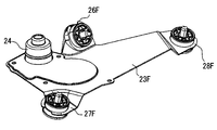
- FIGS. 16 is an external plan view of the rear wiper device 1C according to the fourth embodiment
- FIG. 17 is an external side view of FIG. 16
- FIG. 18 is a partial sectional perspective view of the back door 10
- FIG. 10 is a perspective view of the fixing portions 16 to 18
- FIG. 20 is a partial sectional perspective view of the back door 10 to which the rear wiper device 1C is attached
- FIG. 21 is a sectional side view when the trim cover 19 is attached.
- symbol is attached
- the rear wiper device 1C according to the fourth embodiment is different from the first embodiment in that the attachment surface of the rear wiper motor 36C in the bracket 23C is attached so as to face the inner panel 13 of the back door 10.
- the output shaft 25 protrudes on the opposite side of the bracket 23 ⁇ / b> C and is inserted into the output shaft insertion hole 12 ⁇ / b> C of the windshield 11.
- a shaft holding portion 84 is formed integrally with the housing 22C.
- the shaft holding portion 84 is provided with a cylindrical portion 84c that houses the clutch 43, and a shaft support portion 84a that is provided at the tip of the cylindrical portion 84c and to which a bearing 55 that supports the output shaft 25 is attached. . Since the housing 22C is integrally formed with the cylindrical portion 84c and the shaft support portion 84a by die-casting aluminum or an aluminum alloy, for example, it can be easily manufactured.
- bracket 23C can be directly attached to the opening side of the housing 22C, it is possible to reduce the number of assembling steps.
- an inner cover (not shown) can be provided so as to cover the opening side of the rear wiper motor 36C.
- the inner cover can be temporarily fixed to the bracket 23C by providing the claw insertion portion 76C on the housing 22C side and the claw portion 75C on the inner cover side.
- the bracket 23C is provided with first to third mounting legs 26C to 28C. Since the rear wiper motor 36C is provided on the mounting surface side of the bracket 23C to the inner panel 13, the lengths of the first to third mounting legs 26C to 28C are set so that the rear wiper motor 36C does not contact the inner panel 13. It is necessary to make it longer than in the first embodiment (see FIG. 17).
- the mounting legs 26C to 28C extend from the mounting surface of the rear wiper motor 36C in the bracket 23C toward the projecting side of the output shaft 25.
- a straight line connecting the second mounting leg 27C and the third mounting leg 28C is substantially parallel to the bottom side of the bracket 23C that is substantially parallel to the axial direction of the motor body 20.
- the first to third mounting legs 26C to 28C viewed from the output shaft 25 side, the center of gravity of the rear wiper motor 36C, the inclination angle of the first to third mounting legs 26C to 28C,
- the arrangement of the first to third fixing portions 16 to 18 provided on the inner panel 13 of the back door 10 is the same as that of the first embodiment.
- first mounting leg 26C is disposed in a region surrounded by the axis L3, the perpendicular L6, the straight line L7, and the straight line L9, and the distance R1 ⁇ distance R2, the distance R1 ⁇ distance R3, the distance R1 ⁇ distance R4, and the distance It is the same as in the first embodiment in that the second mounting leg 27C and the third mounting leg 28C are disposed at positions where R5 ⁇ distance R6, and the motor main body 20 is sandwiched therebetween.
- the first to third mounting legs 26C to 28C are provided in positions in a dead space where the rear wiper motor 36C is not disposed and in positions close to the rear wiper motor 36C.
- the size of the bracket 23C can be designed to be small.
- interval of the inner panel 13 and the bracket 23C can be narrowed. Therefore, the trim cover 19 can be provided close to the rear wiper motor 36C and the inner panel 13, the trim cover 19 can be designed to be small, and a space in the vehicle interior can be increased. Since the size of the bracket 23C can be designed to be small, the weight of the bracket 23C can be reduced.
- first to third mounting legs 26C to 28C can be mounted in a limited space of the inner panel 13 of the vehicle back door 10, the shape of the bracket 23 is common regardless of the design of the vehicle back door 10. Can be used. Further, the first to third fixing portions 16 to 18 are provided at positions avoiding the welded portion 15 (joint portion). However, since the size of the bracket 23C can be reduced, the first to third mounting legs 26C to 28C. The design to arrange is easy.
- the first to third mounting legs 26C to 28C are set so as to be inclined at a predetermined angle with respect to the mounting surface of the rear wiper motor 36C of the bracket 23C, so that the output shaft 25 corresponds to the design of the windshield 11. It is set to be inserted into the output shaft insertion hole 12C at a predetermined angle. Further, the inclination angle of the first to third attachment legs 26C to 28C on the bracket 23C side is adjusted by adjusting the inclination of the attachment surfaces of the first to third fixing portions 16 to 18 provided on the back door 10 side of the vehicle. Since the adjustment of the inclination angle can be minimized, the bracket 23C can be shared.
- the first mounting leg 26C is provided above the bracket 23C and at a position avoiding the output shaft 25, all the mounting legs 26C to 28C can be arranged on the upper portion of the inner panel 13. Since vibration is generated by the operation of the rear wiper motor 36C, when the mounting legs 26C to 28C are arranged in the center of the inner panel 13, noise in the vehicle interior may become a problem, but in the first embodiment, Since all the mounting legs 26C to 28C can be arranged on the upper portion of the inner panel 13, it is possible to reduce the noise in the vehicle interior caused by the vibration of the rear wiper motor 36C.
- the first to third mounting legs 26C to 28C are substantially the same with the first mounting leg as an upper vertex and the second mounting leg 27C and the third mounting leg 28C as two lower apexes when viewed from the axial direction of the output shaft 25. Since they are arranged so as to form an isosceles triangle, the right and left balance is improved with respect to the load applied to the rear wiper motor 36C.
- the center of gravity G1 of the rear wiper motor 36C viewed from the axial direction of the output shaft 25 is disposed inside the triangle T constituted by the first to third mounting legs 26C to 28C.
- the center of gravity G1 of the rear wiper motor 36 as viewed from the axial direction of the output shaft 25 is preferably disposed at a position close to the center of gravity G2 of the triangle T formed by the first to third mounting legs 26C to 28C.
- the distance between the center of gravity G1 of the rear wiper motor 36C and the center of gravity G2 of the triangle T is the length of the middle line C drawn from the first mounting leg 26C toward the side connecting the second mounting leg 27C and the third mounting leg 28C. It is set smaller than 1/3 of the length.
- the first mounting leg 26C When viewed from the axial direction of the output shaft 25, the first mounting leg 26C is positioned above the other second mounting legs 27C and the third mounting legs 28C and above the center of gravity of the rear wiper motor 36C. Yes. Further, the second mounting leg 27C and the third mounting leg 28C are arranged at positions sandwiching the motor main body 20 in the axial direction of the motor main body 20, and are second when viewed from the axial direction of the output shaft 25 (in plan view). The intersection of the straight line L1 connecting the mounting leg 27C and the third mounting leg 28C and the perpendicular line L2 drawn from the center of gravity of the rear wiper motor 36C with respect to the straight line L1 is positioned between the second mounting leg 27C and the third mounting leg 28C. Is arranged.
- the first to third mounting legs 26C to 28C in consideration of the center of gravity of the rear wiper motor 36C, the balance between the upper, lower, left and right with respect to the load of the rear wiper motor 36C is improved.
- the vibration associated with the opening and closing of the back door 10 is applied to the rear wiper device 1C.
- the first to third mounting legs 26C to 28C are arranged in consideration of the center of gravity of the rear wiper motor 36C, thereby stabilizing the rear wiper motor 36C. Can be fixed.
- FIGS. 22 is an external plan view of a rear wiper device 1D according to the fifth embodiment
- FIG. 23 is an external side view of FIG. 22
- FIG. 24 is a partial sectional perspective view of the back door 10
- FIG. FIG. 26 is a perspective view of the back door 10 to which the rear wiper device 1D is attached
- FIG. 27 is a sectional side view when the trim cover 19 is attached.
- the components common to those in FIGS. 1 to 21 are denoted by the same reference numerals, and the description thereof is omitted.
- the rear wiper device 1D according to the fifth embodiment is different from the first embodiment in the arrangement of the first mounting legs 26D.
- the arrangement of the second mounting legs 27D and the third mounting legs 28D is the same as in the first embodiment.
- the first mounting leg 26D is provided at a position avoiding the output shaft 25 above the third mounting leg 28D. More specifically, the first mounting leg 26D is provided above the second mounting leg 27D and the third mounting leg 28D and on the opposite side of the motor body 20 with the output shaft 25 interposed therebetween.
- the first mounting leg 26D when viewed from the direction of the output shaft 25, the first mounting leg 26D is perpendicular to the axis L3, the perpendicular L6, the straight line L9, and the end of the third mounting leg 28D disposed on the opposite side of the motor body 20 in the axis L3 direction. It arrange
- first mounting leg 26D is disposed at a position where the distance R1 ⁇ distance R2 and the distance R1 ⁇ distance R3 as viewed from the output shaft 25 direction.
- a straight line connecting the second mounting leg 27D and the third mounting leg 28D is substantially parallel to the bottom side of the bracket 23D that is substantially parallel to the axial direction of the motor body 20.
- the bracket 23D and the shaft holding part 24 are formed as separate bodies.
- the shaft holding part 24 can cover a part of the opening of the housing 22 as in the first embodiment, or can cover the entire opening of the housing 22 as in the second embodiment.
- the shaft holding portion 24 can be formed integrally with the bracket 23D as in the third embodiment.
- the rear wiper motor 36 is attached to the surface of the bracket 23D opposite to the attachment surface of the back door 10 to the inner panel 13, and the relationship of this attachment surface is the same as in the first embodiment. However, similarly to the fourth embodiment, the rear wiper motor 36 can be modified to be mounted on the same side as the mounting surface of the back door 10 to the inner panel 13 in the bracket 23D.
- the rear wiper motor 36 is mounted on the surface opposite to the mounting surface of the bracket 23D to the inner panel 13, the distance between the bracket 23 and the inner panel 13 can be reduced. Further, the first to third mounting legs 26D to 28D are provided at positions in a dead space where the rear wiper motor 36 is not disposed and close to the rear wiper motor 36. In particular, since the first mounting leg 26D is provided above the bracket 23 and at a position avoiding the output shaft 25, the size of the bracket 23D can be designed to be small. For this reason, the trim cover 19 can be provided close to the rear wiper motor 36 and the inner panel 13, the trim cover 19 can be designed to be small, and the space in the vehicle interior can be widened.
- the dimension of the bracket 23D can be designed to be small, the weight of the bracket 23D can be reduced. Further, since the first to third mounting legs 26D to 28D can be mounted in a limited space of the inner panel 13 of the vehicle back door 10, the shape of the bracket 23D is common regardless of the design of the vehicle back door 10. Can be used. Further, the first to third fixing portions 16D to 18D are provided at positions avoiding the welded portion 15 (joint portion). However, since the size of the bracket 23D can be reduced, the first to third mounting legs 26D to 28D. The design to arrange is easy.
- the first to third mounting legs 26D to 28D are set to incline at a predetermined angle with respect to the mounting surface of the rear wiper motor 36 of the bracket 23D, so that the output shaft 25 corresponds to the design of the windshield 11. It is set to be inserted into the output shaft insertion hole 12D at a predetermined angle. Further, the inclination angle of the first to third attachment legs 26D to 28D on the bracket 23D side is adjusted by adjusting the inclination of the attachment surface of the first to third fixing portions 16D to 18D provided on the back door 10 side of the vehicle. Since the adjustment of the inclination angle can be minimized, the bracket 23D can be shared.
- the first mounting leg 26D is provided above the bracket 23D and at a position avoiding the output shaft 25, all the mounting legs 26D to 28D can be arranged on the upper portion of the inner panel 13. Since vibration is generated by the operation of the rear wiper motor 36, when the mounting legs 26D to 28D are arranged in the center of the inner panel 13, noise in the vehicle interior may become a problem. In the first embodiment, however, Since all the mounting legs 26D to 28D can be arranged on the upper portion of the inner panel 13, it is possible to reduce the noise in the vehicle interior caused by the vibration of the rear wiper motor 36.
- the center of gravity G1 of the rear wiper motor 36 viewed from the axial direction of the output shaft 25 is disposed inside the triangle T constituted by the first to third mounting legs 26D to 28D.
- the center of gravity G1 of the rear wiper motor 36 viewed from the axial direction of the output shaft 25 is desirably disposed at a position close to the center of gravity G2 of the triangle T constituted by the first to third mounting legs 26D to 28D.
- the distance between the center of gravity G1 of the rear wiper motor 36 and the center of gravity G2 of the triangle T is the length of the middle line C drawn from the first mounting leg 26D toward the side connecting the second mounting leg 27D and the third mounting leg 28D. It is set smaller than 1/3 of the length.
- the first mounting leg 26D When viewed from the axial direction of the output shaft 25, the first mounting leg 26D is located above the other second mounting legs 27D and the third mounting legs 28D and above the center of gravity of the rear wiper motor 36. Yes. Further, the second mounting leg 27D and the third mounting leg 28D are arranged at positions sandwiching the motor main body 20 in the axial direction of the motor main body 20, and are second when viewed from the axial direction of the output shaft 25 (in plan view). The intersection of the straight line L1 connecting the mounting leg 27D and the third mounting leg 28D and the perpendicular line L2 drawn from the center of gravity of the rear wiper motor 36 with respect to the straight line L1 is positioned between the second mounting leg 27D and the third mounting leg 28D. Is arranged.
- the first to third mounting legs 26D to 28D are arranged in consideration of the center of gravity of the rear wiper motor 36, thereby stabilizing the rear wiper motor 36. Can be fixed.
- FIGS. 28 is an external plan view of the rear wiper device 1E according to the sixth embodiment
- FIG. 29 is an external side view of FIG. 28
- FIG. 30 is a partial sectional perspective view of the back door 10
- FIG. FIG. 32 is a perspective view of the back door 10 with the rear wiper device 1E attached
- FIG. 33 is a sectional side view with the trim cover 19 attached.
- the components common to those in FIGS. 1 to 27 are denoted by the same reference numerals, and description thereof is omitted.
- the rear wiper device 1E according to the sixth embodiment differs from the first embodiment in the arrangement of the second mounting legs 27E and the third mounting legs 28E.
- the arrangement of the first mounting legs 26E is the same as in the first embodiment.
- the first mounting leg 26E is disposed in a region surrounded by the axis L3, the straight line L5, the perpendicular L6, and the straight line L7 when viewed from the output shaft 25 direction, and at a position where the distance R1 ⁇ distance R4 and the distance R5 ⁇ distance R6.
- the second mounting leg 27E and the third mounting leg 28E are disposed below the position where the motor body 20 is sandwiched. Further, the second mounting leg 27E is disposed below the third mounting leg 28E.
- the second attachment leg 27E is arranged above the third attachment leg 28E, or the second attachment leg.
- the thing whose 27E and the 3rd attachment leg 28E are the same height is also included.
- the straight line connecting the second mounting leg 27E and the third mounting leg 28E is substantially parallel to the bottom side of the bracket 23E.
- one of the second mounting leg 27E and the third mounting leg 28E may be disposed at a position overlapping the motor body 20 in the direction of the axis L3, and the other may be disposed below the one.
- the bracket 23E and the shaft holding portion 24 are formed as separate bodies.
- the shaft holding part 24 can cover a part of the opening of the housing 22 as in the first embodiment, or can cover the entire opening of the housing 22 as in the second embodiment.
- the shaft holding portion 24 can be formed integrally with the bracket 23F as in the third embodiment.
- the rear wiper motor 36 is attached to the surface of the bracket 23E opposite to the attachment surface of the back door 10 to the inner panel 13, and the relationship of this attachment surface is the same as in the first embodiment.
- the rear wiper motor 36 can be modified so as to be mounted on the same side as the mounting surface of the back door 10 to the inner panel 13 in the bracket 23E.
- the rear wiper motor 36 is mounted on the surface opposite to the mounting surface of the bracket 23E on the inner panel 13, the distance between the bracket 23E and the inner panel 13 can be reduced. Further, the first to third mounting legs 26E to 28E are provided in positions of dead spaces where the rear wiper motor 36 is not disposed and positions close to the rear wiper motor 36. Particularly, since the first mounting leg 26E is provided above the bracket 23E and avoids the output shaft 25, the size of the bracket 23E can be designed to be small. In addition, since the second mounting leg 27E and the third mounting leg 28E are arranged below the rear wiper motor 36, the distance between the second mounting leg 27E and the third mounting leg 28E can be reduced. The length of the motor body 20 in the axial direction of the bracket 23E can be reduced.
- the trim cover 19 can be provided close to the rear wiper motor 36 and the inner panel 13, the trim cover 19 can be designed to be small, and the space in the vehicle interior can be widened. Since the dimension of the bracket 23E can be designed small, the weight of the bracket 23E can be reduced. Further, since the first to third mounting legs 26E to 28E can be mounted in a limited space of the inner panel 13 of the vehicle back door 10, the shape of the bracket 23E is common regardless of the design of the vehicle back door 10. Can be used. Furthermore, although the first to third fixing portions 16E to 18E are provided at positions avoiding the welded portion 15 (joint portion), the dimensions of the bracket 23E can be reduced, so the first to third mounting legs 26E to 28E. The design to arrange is easy.
- the first to third mounting legs 26E to 28E are set to incline at a predetermined angle with respect to the mounting surface of the rear wiper motor 36 of the bracket 23E, so that the output shaft 25 corresponds to the design of the windshield 11. It is set to be inserted through the output shaft insertion hole 12 at a predetermined angle. Further, the inclination angle of the first to third attachment legs 26E to 28E on the bracket 23E side is adjusted by adjusting the inclination of the attachment surface of the first to third fixing portions 16E to 18E provided on the back door 10 side of the vehicle. Since the adjustment of the inclination angle can be minimized, the bracket 23E can be shared.
- the first mounting legs 26E are provided above the bracket 23E and avoid the output shaft 25, all the mounting legs 26E to 28E can be disposed on the inner panel 13. Since vibration is generated by the operation of the rear wiper motor 36, when the mounting legs 26E to 28E are arranged at the center of the inner panel 13, noise in the vehicle interior may become a problem. In the first embodiment, however, Since all the mounting legs 26E to 28E can be arranged on the upper portion of the inner panel 13, it is possible to reduce noise in the vehicle interior caused by the vibration of the rear wiper motor 36.
- the second mounting leg 27E is disposed at a position lower than the third mounting leg 28E.
- the second mounting leg 27E is disposed at a position higher than the third mounting leg 28E.
- the heights of the second mounting leg 27E and the third mounting leg 28E can be made equal, and the degree of freedom in designing the bracket 23E can be increased.
- the center of gravity G1 of the rear wiper motor 36 viewed from the axial direction of the output shaft 25 is disposed inside the triangle T constituted by the first to third mounting legs 26E to 28E.
- the center of gravity G1 of the rear wiper motor 36 viewed from the axial direction of the output shaft 25 is desirably disposed at a position close to the center of gravity G2 of the triangle T constituted by the first to third mounting legs 26E to 28E.
- the distance between the center of gravity G1 of the rear wiper motor 36 and the center of gravity G2 of the triangle T is the length of the middle line C drawn from the first mounting leg 26E toward the side connecting the second mounting leg 27E and the third mounting leg 28E. It is set smaller than 1/3 of the length.
- the first mounting leg 26E When viewed from the axial direction of the output shaft 25, the first mounting leg 26E is positioned above the other second mounting legs 27E and the third mounting legs 28E and above the center of gravity of the rear wiper motor 36. Yes. Further, the second mounting leg 27E and the third mounting leg 28E are arranged at positions sandwiching the motor main body 20 in the axial direction of the motor main body 20, and are second when viewed from the axial direction of the output shaft 25 (in plan view). The intersection of the straight line L1 connecting the mounting leg 27E and the third mounting leg 28E and the perpendicular line L2 drawn from the center of gravity of the rear wiper motor 36 with respect to the straight line L1 is positioned between the second mounting leg 27E and the third mounting leg 28E. Are arranged.
- the first to third mounting legs 26E to 28E in consideration of the center of gravity of the rear wiper motor 36, the balance in the vertical and horizontal directions with respect to the load of the rear wiper motor 36 is improved.
- the vibration associated with the opening and closing of the back door 10 is applied to the rear wiper device 1, but the first to third mounting legs 26E to 28E are arranged in consideration of the center of gravity of the rear wiper motor 36, thereby stabilizing the rear wiper motor 36.
- FIGS. 34 is an external plan view of the rear wiper device 1F according to the seventh embodiment
- FIG. 35 is an external side view of FIG. 34
- FIG. 36 is a perspective view of the bracket 23F
- FIG. 37 is a side view of FIG. 38 is a partial sectional perspective view of the back door 10
- FIG. 39 is a perspective view of the fixing portions 16F to 18F of the back door 10
- FIG. 40 is a perspective view of the back door 10 to which the rear wiper device 1F is attached.
- FIG. 41 is a cross-sectional side view when the trim cover 19 is attached.
- symbol is attached
- the rear wiper device 1F according to the seventh embodiment differs from the first embodiment in terms of the inclination angle of the first mounting leg 26F.
- the arrangement of the first mounting legs 26F is substantially the same as in the first embodiment.
- the first mounting legs 26F are arranged in a region surrounded by the axis L3, the straight line L5, the perpendicular L6, and the straight line L7 when viewed from the output shaft 25 direction.
- the arrangement and inclination angle of the second mounting leg 27F and the third mounting leg 28F are the same as those in the first embodiment.
- a straight line connecting the second mounting leg 27F and the third mounting leg 28F is substantially parallel to the bottom side of the bracket 23F that is substantially parallel to the axial direction of the motor body 20.
- the inclination angle of the second attachment leg 27F and the third attachment leg 28F is substantially the same, and the inclination angle of the first attachment leg 26F is substantially 45 degrees with respect to the inclination angle of the second attachment leg 27F and the third attachment leg 28F. Only has a steep slope.
- the disclosure does not limit the tilt angle of the first mounting leg 26F, and the tilt angle of the first mounting leg 26F can be freely designed.
- the tilt angle of the first mounting leg 26F can be set to the second mounting leg.
- the inclination angle of the first attachment leg 26F is set so as to be more gentle with respect to the inclination angle of the leg 27F and the third attachment leg 28F, and the inclination angle of the second attachment leg 27F and the third attachment leg 28F is set.
- FIGS. 36 and 37 only the inclination angle of the first mounting leg 26F is illustrated as different from the other mounting legs 27F and 28F.
- the disclosure is not limited to this, for example, the second mounting leg 26F.
- the inclination angle of the leg 27F is different from the other attachment legs 26F, 28F
- the inclination angle of the third attachment leg 28F is different from the other attachment legs 26F, 27F
- the inclination angles of all the attachment legs 26F, 27F, 28F Different things are also included.
- the angles of the mounting legs 26F to 28F are set so that the angle difference between the mounting legs 26F to 28F is in the range of 0 degrees to 70 degrees.
- the assembly of the rear wiper motor 36 (rear wiper device 1) to the inner panel 13 can be simplified, and the assemblability is improved. Can be improved.
- the bracket 23F and the shaft holding portion 24 are formed as separate bodies.
- the shaft holding part 24 can cover a part of the opening of the housing 22 as in the first embodiment, or can cover the entire opening of the housing 22 as in the second embodiment.
- the shaft holding portion 24 can be formed integrally with the bracket 23F as in the third embodiment.
- the rear wiper motor 36 is attached to the surface of the bracket 23F opposite to the attachment surface of the back door 10 to the inner panel 13, and the relationship of this attachment surface is the same as in the first embodiment.
- the rear wiper motor 36 can be modified so as to be mounted on the same side as the mounting surface of the back door 10 to the inner panel 13 in the bracket 23F.
- the distance between the bracket 23 and the inner panel 13 can be reduced.
- the first to third mounting legs 26F to 28F are provided at positions in a dead space where the rear wiper motor 36 is not disposed and at positions close to the rear wiper motor 36.
- the first mounting leg 26F is provided above the bracket 23 and at a position avoiding the output shaft 25, the size of the bracket 23 can be designed to be small. For this reason, the trim cover 19 can be provided in the vicinity of the rear wiper motor 36 and the inner panel 13, and a space in the vehicle compartment can be increased.
- the dimension of the bracket 23F can be designed to be small, the weight of the bracket 23F can be reduced. Further, since the first to third mounting legs 26F to 28F can be mounted in a limited space of the inner panel 13 of the vehicle back door 10, the shape of the bracket 23F is common regardless of the design of the vehicle back door 10. Can be used. Further, the first to third fixing portions 16F to 18F are provided at positions avoiding the welded portion 15 (joint portion). However, since the size of the bracket 23F can be reduced, the first to third mounting legs 26F to 28F are provided. The design to arrange is easy.
- the first to third mounting legs 26F to 28F are set so as to be inclined at a predetermined angle with respect to the mounting surface of the rear wiper motor 36 of the bracket 23F, so that the output shaft 25 corresponds to the design of the windshield 11. It is set to be inserted through the output shaft insertion hole 12 at a predetermined angle. Since the inclination angle of the first attachment leg 26F is different from the inclination angles of the second attachment leg 27F and the third attachment leg 28F, the degree of freedom in designing the inclination angle can be improved. Further, the inclination angle of the first to third attachment legs 26F to 28F on the bracket 23 side is adjusted by adjusting the inclination of the attachment surface of the first to third fixing portions 16F to 18F provided on the back door 10 side of the vehicle. Since the adjustment of the inclination angle can be minimized, the bracket 23F can be shared.
- the first mounting leg 26F is provided above the bracket 23F and at a position avoiding the output shaft 25, all the mounting legs 26F to 28F can be arranged on the upper portion of the inner panel 13. Since vibration is generated by the operation of the rear wiper motor 36, when the mounting legs 26F to 28F are arranged in the center of the inner panel 13, noise in the vehicle interior may become a problem. In the first embodiment, however, Since all the mounting legs 26F to 28F can be arranged on the upper portion of the inner panel 13, it is possible to reduce vehicle interior noise caused by vibration of the rear wiper motor 36.
- the first to third mounting legs 26F to 28F have the first mounting leg 26F as the upper apex and the second mounting leg 27F and the third mounting leg 28F as the lower two apexes when viewed from the axial direction of the output shaft 25. Since they are arranged so as to form a substantially isosceles triangle, the left-right balance is improved with respect to the load applied to the rear wiper motor 36.
- the center of gravity G1 of the rear wiper motor 36 viewed from the axial direction of the output shaft 25 is disposed inside the triangle T constituted by the first to third mounting legs 26F to 28F.
- the center of gravity G1 of the rear wiper motor 36 viewed from the axial direction of the output shaft 25 is desirably disposed at a position close to the center of gravity G2 of the triangle T formed by the first to third mounting legs 26F to 28F.
- the distance between the center of gravity G1 of the rear wiper motor 36 and the center of gravity G2 of the triangle T is the length of the middle line C drawn from the first mounting leg 26F toward the side connecting the second mounting leg 27F and the third mounting leg 28F. It is set smaller than 1/3 of the length.
- the first mounting leg 26F When viewed from the axial direction of the output shaft 25, the first mounting leg 26F is located above the other second mounting legs 27F and the third mounting legs 28F and above the center of gravity of the rear wiper motor 36. Yes. Further, the second mounting leg 27F and the third mounting leg 28F are arranged at positions sandwiching the motor main body 20 in the axial direction of the motor main body 20, and are second when viewed from the axial direction of the output shaft 25 (in plan view). The intersection of the straight line L1 connecting the mounting leg 27F and the third mounting leg 28F and the perpendicular line L2 drawn from the center of gravity of the rear wiper motor 36 with respect to the straight line L1 is positioned between the second mounting leg 27F and the third mounting leg 28F. Is arranged.
- the first to third mounting legs 26F to 28F are arranged in consideration of the center of gravity of the rear wiper motor 36, thereby stabilizing the rear wiper motor 36. Can be fixed.
Landscapes
- Engineering & Computer Science (AREA)
- Mechanical Engineering (AREA)
- Motor Or Generator Frames (AREA)
- Connection Of Motors, Electrical Generators, Mechanical Devices, And The Like (AREA)
Abstract
リアワイパ装置は、車両のインナパネルに対してブラケットにより装着されたワイパモータを備える。ブラケットは第1の取付脚を含む複数の取付脚によりインナパネルに固定されている。平面視において、第1の取付脚は、第1から第4の線により囲まれた領域内に位置する。第1線は、モータ本体の軸線である。第2線は、ハウジングの上端を通るモータ本体の軸線に対して平行に引いた直線である。第3線は、モータ本体のヨークの底面からモータ本体の軸線に対して垂直に引いた直線である。第4線は、垂線の他方側に設けられたひとつの取付脚の端部を通るモータ本体の軸線に対して垂直に引いた直線である。
Description
この出願は、2017年4月11日に出願された日本特許出願2017-078550号を基礎出願とするものであり、当該基礎出願の開示内容は参照によってこの出願に組み込まれている。
この開示は、車両のリアウインドウを払拭するリアワイパ装置、リアワイパ装置の取付構造、及び、車両のバックドアに関する。
ワゴン車やハッチバック車における車両後方の荷室を開閉するためのバックドアには、リアガラスを払拭するためにリアワイパ装置が装着されている。先端にワイパブレードが装着されたワイパアームを駆動するワイパモータは金属製のブラケットにより、車体のインナパネルに取り付けられている。そして、ワイパアームに接続されているピボット軸はリアガラスに設けられた挿通孔に挿通されているが、リアガラスの傾斜は車種によって異なるため、ピボット軸の取り付け角度もリアガラスの傾斜に対応して異なる。そこで、車種によらずブラケットを共用できるようにすることが検討されている。
特許文献1には、リアワイパ装置のワイパアームを駆動するワイパモータをインナパネルに装着するためのブラケットに3つの取付脚を設け、各取付脚をインナパネルに取り付けることにより、ワイパモータをインナパネルに装着することが記載されている。そして、ブラケットに設けられた一対の係止凸部を、トリム側に設けられた一対の係止部の係止穴に係合させることにより、ブラケットの角度が異なった場合にも、共通化できるブラケットとトリムの係合構造が提案されている。
特許文献2は、モータの重心と、取付脚の配置とについて開示している。特許文献3は、ハウジング開口部を覆うインナカバーについて開示している。
上記特許文献1に記載のリアワイパ装置ではブラケットとトリムとの係合構造の共通化が提案されているが、ブラケットとインナパネルとの結合構造を共通化するものではない。すなわち、インナパネルの構造は車種によって異なるため、車種ごとにブラケットのインナパネルへの取付脚の配置を変更する必要があった。また、インナパネルには凹凸や孔が存在するので、インナパネルの形状に適合してワイパモータを安定して固定するためには、取付脚を所望の方向へ屈曲しつつ長く伸ばす必要があり、また、ブラケットが車室内に張り出すこともあった。そして、ブラケットとして大きいものが必要となると、軽量化の観点からも問題があった。特許文献2および特許文献3は、このような課題を解決するものではない。
開示される目的は、ブラケットの軽量化及び、省スペース化を図り、ブラケットのインナパネルへの結合構造を共通化することにある。
開示される他の目的は、リアワイパ装置を取り付けるためのリアワイパ装置の取付構造を提供することにある。
開示される他の目的は、リアワイパ装置を取り付けたバックドアを提供することにある。
上記目的は、以下の構成によって達成できる。すなわち、ひとつの実施態様のリアワイパ装置は、車両のインナパネルに対してブラケットにより装着されたワイパモータを備えるリアワイパ装置であって、ワイパモータは、ハウジングと、ハウジングに締結されたモータ本体と、モータ本体の回転軸の回転を減速する減速機構と、減速機構で減速された回転を出力する出力軸と、を備え、出力軸にはウインドシールドを払拭するワイパ本体が接続され、ブラケットは第1の取付脚と第1の取付脚とは異なる2つの取付脚とを含む複数の取付脚によりインナパネルに固定され、平面視、かつ、インナパネルへの固定姿勢において、2つの取付脚は、第1の取付脚より下側に配置されるモータ本体の軸線に対して出力軸の軸線から引かれる垂線の一方側と他方側とに配置され、一方側にモータ本体が配置されており、平面視において、第1の取付脚は、モータ本体の軸線(L3)と、ハウジングの上端を通るモータ本体の軸線に対して平行に引いた直線(L9)と、モータ本体のヨークの底面からモータ本体の軸線に対して垂直に引いた直線(L7)と、垂線の他方側に設けられたひとつの取付脚の端部を通るモータ本体の軸線に対して垂直に引いた直線(L10)とに囲まれた領域内に位置することを特徴とする。
ひとつの実施態様のリアワイパ装置は、第1の取付脚は他の取付脚よりも出力軸側であると共に、ワイパモータの重心よりも上方であり、かつ、出力軸の軸方向視にて減速機構及び出力軸と重ならない位置に配置され、他の取付脚の中の2つの取付脚は出力軸の軸方向視にてモータ本体を挟む位置、あるいは、2つの取付脚の少なくとも一方がモータ本体を挟む位置よりも第1の取付脚とは反対側に配置され、かつ、平面視で2つの取付脚を結ぶ直線とワイパモータの重心から直線に対して引いた垂線との交点が、2つの取付脚の中間に位置するように配置されていることを特徴とする。
ひとつの実施態様のリアワイパ装置は、平面視でワイパモータの重心が第1の取付脚及び2つの取付脚を結ぶ三角形の内側に配置されることを特徴とする。
ひとつの実施態様のリアワイパ装置は、平面視でワイパモータの重心と三角形の重心との距離は、第1の取付脚から、2つの取付脚を結ぶ辺へ向けて引いた中線の長さの1/3の長さよりも小さく設定されることを特徴とする。
ひとつの実施態様のリアワイパ装置は、平面視で第1の取付脚は、モータ本体の軸線と、出力軸の軸線からモータ本体の軸線に対して平行に引いた直線と、モータ本体のヨークの底面からモータ本体の軸線に対して垂直に引いた直線と、出力軸の軸線からモータ本体の軸線に対して垂直に引いた直線とに囲まれた領域内に位置することを特徴とする。
ひとつの実施態様のリアワイパ装置は、平面視で第1の取付脚は、モータ本体の軸線と、出力軸の軸線からモータ本体の軸線に対して平行に引いた直線と、出力軸の軸線からモータ本体の軸線に対して垂直に引いた直線と、2つの取付脚の中のモータ本体とは反対側に設けられた取付脚の端部からモータ本体の軸線に対して垂直に引いた直線とに囲まれた領域内に位置することを特徴とする。
ひとつの実施態様のリアワイパ装置は、平面視で2つの取付脚を結ぶ直線がブラケットの辺と略平行であることを特徴とする。
ひとつの実施態様のリアワイパ装置は、ハウジングは有底箱状であり、ブラケットはハウジングの開口側を覆っていることを特徴とする。
ひとつの実施態様のリアワイパ装置は、ハウジングの開口側には、ブラケットとの間にインナカバーが設けられていることを特徴とする。
ひとつの実施態様のリアワイパ装置は、ワイパモータはブラケットのインナパネルへの取付面側に取り付けられ、出力軸はインナパネル側へ突出していることを特徴とする。
ひとつの実施態様のリアワイパ装置は、ワイパモータはブラケットのインナパネルへの取付面とは反対側の面に取り付けられ、出力軸はインナパネル側へ突出していることを特徴とする。
ひとつの実施態様のリアワイパ装置は、出力軸は軸保持部により保持されており、軸保持部はブラケットとは別体に形成されていることを特徴とする。
ひとつの実施態様のリアワイパ装置は、出力軸は軸保持部により保持されており、軸保持部はブラケットとは一体に形成されていることを特徴とする。
ひとつの実施態様のリアワイパ装置は、ワイパモータはブラケットのインナパネルへの取付面とは反対側の面に取り付けられ、出力軸はインナパネル側へ突出し、出力軸は軸保持部により保持されており、軸保持部はブラケットとは別体に形成されており、軸保持部はインナカバーと一体に形成されていることを特徴とする。
ひとつの実施態様のリアワイパ装置は、取付脚はブラケット平面に対して所定の傾斜角度に設定されていることを特徴とする。
ひとつの実施態様のリアワイパ装置は、モータ本体の軸線方向視において、第1の取付脚は、ブラケットの平面より出力軸の突出方向に位置することを特徴とする。
ひとつの実施態様のリアワイパ装置は、平面視において、第1の取付脚は、第1の取付脚の中心から、モータ本体の軸線に対して出力軸から垂直に引いた直線までの距離が、2つの取付脚のそれぞれの中心から、モータ本体の軸線に対して出力軸から垂直に引いた直線までの距離より短くなる(R1<R2、R1<R3)位置に配置されていることを特徴とする。
ひとつの実施態様のリアワイパ装置は、平面視において、第1の取付脚は、第1の取付脚の中心からモータ本体の軸線までの距離より、第1の取付脚の中心から出力軸の軸線を通るモータ本体の軸線に対して平行に引いた直線までの距離が短くなる(R1<R4)と共に、第1の取付脚の中心からモータ本体のヨークの底面を通るモータ本体の軸線に対して垂直に引いた直線までの距離より、第1の取付脚の中心から出力軸の軸線を通るモータ本体の軸線に対して垂直に引いた直線までの距離が短くなる(R5<R6)位置に配置されていることを特徴とする。
ひとつの実施態様の取付構造は、上記リアワイパ装置の第1の取付脚は、インナパネルに設けられたアウタパネルとの接合部を避けてインナパネルに固定されていることを特徴とする。
ひとつの実施態様の車両のバックドアは、上記リアワイパ装置又は上記リアワイパ装置の取付構造を備えることを特徴とする。
ひとつの実施態様のリアワイパ装置によれば、第1の取付脚を出力軸の周辺に配置することができ、取付脚の長さ、ひいてはブラケットの面積を低減することができるためにブラケットの軽量化を図ることができると共に、省スペース化を図ることができる。また、第1の取付脚をウインドシールドの下部の凹凸が少ない、又は孔がないインナパネルへ固定することができるために、ブラケットの共通化を図ることができる。
ひとつの実施態様のリアワイパ装置によれば、各取付脚にかかる荷重を均等化することができる。
ひとつの実施態様のリアワイパ装置によれば、ブラケットを用いてワイパモータをより安定して固定することができる。
ひとつの実施態様のリアワイパ装置によれば、第1の取付脚を減速機構及び出力軸を避ける位置に適切に配置される。
ひとつの実施態様のリアワイパ装置によれば、第5の態様の場合と同様に、第1の取付脚を減速機構及び出力軸を避ける位置に適切に配置される。
ひとつの実施態様のリアワイパ装置によれば、取付脚の長さを短くすることができる。
ひとつの実施態様のリアワイパ装置によれば、ブラケットでハウジングのカバーを兼ねることができる。
ひとつの実施態様のリアワイパ装置によれば、ワイパモータを輸送する際に、インナカバーによりハウジングの開口を塞ぐことができる。
ひとつの実施態様のリアワイパ装置によれば、ワイパモータはブラケットのインナパネルへの取付面側に取り付けられているので、出力軸をワイパモータと同じ方向に配置することができる。
ひとつの実施態様のリアワイパ装置によれば、取付脚をより短くすることができる。
ひとつの実施態様のリアワイパ装置によれば、軸保持部をブラケットとは別体に形成することにより、ブラケット及び軸保持部の製造が容易である。
ひとつの実施態様のリアワイパ装置によれば、組立工数を低減することができる。
ひとつの実施態様のリアワイパ装置によれば、軸保持部とインナカバーとを一体に形成することにより、部品点数を低減すると共に、製造が容易となる。
ひとつの実施態様のリアワイパ装置によれば、取付脚の角度を適切に設定することにより、出力軸の突出角度を調整することができる。
ひとつの実施態様のリアワイパ装置によれば、第1の取付脚がブラケットの平面よりも出力軸の突出方向に位置するため、第1の取付脚とインナパネルまでの距離を近くできる。この結果、第1の取付脚の長さを短くすることができる。
ひとつの実施態様のリアワイパ装置によれば、出力軸の近くに第1の取付脚を配置することができるため、ブラケットの大型化を抑制することができる。
ひとつの実施態様のリアワイパ装置によれば、出力軸の近くに第1の取付脚を配置することができるため、ブラケットの大型化をより抑制することができる。
ひとつの実施態様のリアワイパ装置の取付構造によれば、リアワイパ装置の効果を奏すると共に、ブラケットをインナパネルの適切な位置に固定することができるリアワイパ装置の取付構造を提供することができる。
ひとつの実施態様の車両のバックドアによれば、リアワイパ装置又はリアワイパ装置の取付構造の効果を奏する車両のバックドアを提供することができる。
以下、図面を参照して実施形態に係るリアワイパ装置を説明する。但し、以下に示す実施形態は、開示される技術思想を具体化するためのリアワイパ装置を例示するものであって、開示をこれらに特定するものではなく、特許請求の範囲に含まれるその他の実施形態のものにも等しく適用し得るものである。また、「引いた直線」などは、実際に描かれた実在の線を指すのではない。「引いた直線」などは、仮想的に設定された仮想の直線を指すものとして理解されるべきである。車両におけるリアワイパ装置の固定姿勢は、インナパネルへの固定姿勢としていくつかの図に示されている。それらの図において、矢印Gは、重力の方向を示している。重力の方向は、鉛直方向とも呼ばれる。「上」、または「下」の語は、リアワイパ装置の固定姿勢における相対的な上下関係を指すものとして理解されるべきである。
<第1実施形態>
第1実施形態に係るリアワイパ装置1について、図1~図11を参照して説明する。
第1実施形態に係るリアワイパ装置1について、図1~図11を参照して説明する。
まず、図1~図5を用いて、第1実施形態に係るリアワイパ装置1の概略構成について説明する。なお、図1は第1実施形態に係るリアワイパ装置1の外観平面図であり、図2は図1の外観側面図であり、図3は図1の外観下面図であり、図4はリアワイパモータ36の下面図であり、図5はクラッチ43の断面図である。
<リアワイパ装置1の概略構成>
リアワイパ装置1は、車両のバックドア10のインナパネル13に取り付けられ、出力軸25に接続されたワイパ本体4によりバックドア10のウインドシールド11を払拭する。ワイパ本体4はワイパアーム2及びワイパアーム2に接続されたワイパブレード3からなり、ワイパアーム2の一端が出力軸25に接続されている。そして、ワイパモータとしてのリアワイパモータ36により出力軸25が正逆回転可能に駆動され、出力軸25によりワイパアーム2が揺動運動されることにより、ワイパブレード3がウインドシールド11面の下反転位置と上反転位置との間を往復払拭されるようにワイパ本体4が構成されている。
リアワイパ装置1は、車両のバックドア10のインナパネル13に取り付けられ、出力軸25に接続されたワイパ本体4によりバックドア10のウインドシールド11を払拭する。ワイパ本体4はワイパアーム2及びワイパアーム2に接続されたワイパブレード3からなり、ワイパアーム2の一端が出力軸25に接続されている。そして、ワイパモータとしてのリアワイパモータ36により出力軸25が正逆回転可能に駆動され、出力軸25によりワイパアーム2が揺動運動されることにより、ワイパブレード3がウインドシールド11面の下反転位置と上反転位置との間を往復払拭されるようにワイパ本体4が構成されている。
リアワイパ装置1は、リアワイパモータ36及びブラケット23を備えている。そして、リアワイパモータ36は、モータ本体20及びギヤ部35を備えている。モータ本体20は、例えば直流ブラシモータで構成されている。モータ本体20は、該モータ本体20の筐体としてのヨーク32を含むステータと、ステータと同心状でステータの内側に回転自在に支持されたロータ(図示省略)とから構成されている。ヨーク32は、鉄等の磁性材料からなる略有底円筒状に構成され、ヨーク32の円筒部の内周側には4極の永久磁石(図示省略)がN極とS極が周方向に交互に配列されるように設けられている。ロータの中心には丸棒状の回転軸が有底円筒状のヨーク32と同軸上に設けられている。ヨーク32の非開口側(底部側)には軸受が設けられており、回転軸の一端(図4の右側)を回転可能に軸支している。回転軸の他端側には後述するウォーム40が設けられている。ヨーク32の開口側には、ヨーク32の開口端から回転軸の軸線と直交方向外側に張り出したフランジ21が設けられている。このフランジ21がハウジング22に対してネジ等により固定されることで、ヨーク32(モータ本体20)とハウジング22(ギヤ部35)とが締結固定されている。
ロータには、永久磁石の内周面と対向するようにアーマチャが設けられており、このアーマチャはコイルが巻回された複数極の磁極を有し、各磁極が永久磁石と対向している。また、ロータのヨーク32の開口側には、コイルに導通されるコミュテータが設けられており、該コミュテータにブラシホルダ(図6参照)に支持された複数のブラシが摺接することにより、コイルに通電する構成となっている。そして、ブラシは、コネクタ33に電気的に接続しており、コネクタ33に接続される外部電源(図示省略)からの電力が供給されるようになっている。
なお、実施形態では、モータ本体20を直流モータとしてのブラシ付モータで説明しているが、モータ本体20のモータの形式は、これに限定されず、例えばブラシレスモータ等、どのような形式のモータでも適用できる。また、第1実施形態においては、モータ本体20は一方向回転型のモータについて説明するが、これに限定されるものではなく、開示は、例えば、正逆回転可能なモータも包含する。正逆回転可能なモータを用いる場合には揺動機構を省略することができる。
ギヤ部35は、有底箱状の金属製ハウジング22内に設けられており、モータ本体20の回転軸に接続されたウォーム40、ウォーム40に噛合されたウォームホイール41、ウォームホイール41の減速連結軸41aに軸連結された揺動ロッド42、揺動ロッド42のセクタギヤ42bに噛合された第1結合プレートを含むクラッチ43、クラッチ43の出力に接続された出力軸25、及び、出力軸25とクラッチ43の周囲を覆う軸保持部24とを備えている。ハウジング22は、例えばアルミニウム又はアルミニウム合金をダイキャスト成形することにより形成されている。軸保持部24は例えば鉄板で形成されており、出力軸25及びクラッチ43の周囲で、出力軸25側に円筒状に突出した円筒部24cが設けられている。円筒部24cの先端側には出力軸25を軸支する軸受55が設けられた軸支部24aが形成されており、軸支部24aには出力軸25が挿通されている。円筒状の突出部における基端側の内周には、案内部材56が設けられており、後述の第1係合プレート50における出力軸25突出側の外周を軸支している。また、軸保持部24の円筒状の突出部における基端部側の外周にはハウジング22の開口に対向する平板部24bが設けられている。平板部24bは、ハウジング22の出力軸25側の短辺(図4の上辺)から出力軸25及びクラッチ43の周囲と、ウォームホイール41の一部とを覆うように、ハウジング22の開口に対向して、複数の雄ネジ48により、ブラケット23と共にネジ留めされている。このように第1実施形態では、平板部24bは、ハウジング22の開口の一部を覆うように設けられているが、この実施形態は、ハウジング22の開口を覆う範囲を限定するものではなく、平板部24bがハウジング22の開口を覆う範囲は各部の寸法や形状に応じて変更可能である。
ハウジング22には、ギヤ部35を収容するギヤ収容部45とモータ本体20のフランジ21を連結するフランジ連結部46とが一体に成形されている。このフランジ連結部46は、フランジ21の外形に対応する形状をしており、フランジ連結部46とフランジ21とはネジ等により締結固定されている。フランジ連結部46のフランジ21取付面とは反対側にはギヤ収容部45が一体に形成されている。ギヤ収容部45は、モータ本体20の回転軸の径方向の一方で、かつ、出力軸25の突出方向に開口する有底箱状に形成されており、ギヤ部35を収容している。また、ギヤ収容部45の縁部には複数の雌ネジ47が設けられており、この中で出力軸25の周辺にある雌ネジ47には軸保持部24及びブラケット23が雄ネジ48により締結固定され、その他の雌ネジ47にはブラケット23が雄ネジ48により締結固定される。ギヤ収容部45は、出力軸25側から見て、ウォーム40収容部を一方側の短辺とし、ウォーム40の軸線と垂直方向を長辺とする略矩形状(図4において左右方向が短辺、上下方向が長辺の矩形形状)である。モータ本体20の回転軸の他端側(図4の左側)にはウォーム40が転造等によって形成されている。このウォーム40を含む回転軸の他端側は、ギヤ収容部45の内部に入り込んでおり、ウォーム40の両端は軸受により軸支されている。
また、ギヤ収容部45においてウォーム40の側方(図4の紙面上方)には、例えば樹脂材料よりなり円板状をなすウォームホイール41が配置されている。ウォームホイール41は、ウォーム40に噛み合った状態で、ハウジング22の開口方向及びその反対方向を軸方向とする軸周りに回転自在に支持されている。ウォーム40とウォームホイール41とにより減速機構が構成される。ウォームホイール41におけるハウジング22の開口方向の面には、回転中心から外周側(径方向外側)にずれた位置に、金属製の減速連結軸41aをがたつきなく回転可能に挿入する挿入孔(図示省略)が設けられている。減速連結軸41aの先端は、揺動ロッド42の一端(図4の紙面下方側)に設けられた固定孔42aに圧入されているので、揺動ロッド42は減速連結軸41aを中心に回転可能となっている。揺動ロッド42の他端側(図4の紙面上方側)における出力軸25側の側面には、クラッチ43を構成する第1係合プレート50の外周に設けられたギヤ歯50aに噛み合う、セクタギヤ42bが設けられている。
クラッチ43は、ギヤ収容部45のウォームホイール41を挟んでウォーム40の反対側の位置であり、かつ、ギヤ収容部45の短辺方向でのモータ本体20寄りに設けられている。クラッチ43の反モータ本体20側には、揺動ロッド42におけるセクタギヤ42b側(図4の紙面上方側)が揺動できるだけの空間が設けられている。クラッチ43は、中央挿入孔50bに出力軸25が回転可能に挿入された第1係合プレート50、第1係合プレートに凹凸係合して一体回転可能であると共に凹凸係合を解除可能である第2係合プレート51、第2係合プレート51を第1係合プレート50に押圧するコイルスプリング53、第2係合プレート51とコイルスプリング53を挟んで対向する規制プレート52、及び、第2係合プレート51と規制プレート52と一体に回転する出力軸25を備えている。第1係合プレート50の軸線方向で出力軸25の突出側の外周は、案内部材56により軸支されており、第1係合プレート50の軸線方向で出力軸25の反突出側の外周にはセクタギヤ42bと噛み合うギヤ歯50aが設けられている。第1係合プレート50の軸線方向で出力軸25の突出側の端面には、第2係合プレート51と凹凸係合する周方向に凹凸を繰り返す凹凸面が設けられている。第2係合プレート51における軸線方向で出力軸25の反突出側の端面には第1係合プレートの凹凸面の形状と対応する凹凸面が設けられている。
第2係合プレート51及び規制プレート52の中央には、出力軸25を嵌合して固定するための嵌合孔がそれぞれ設けられており、第2係合プレート51、規制プレート52、及び、出力軸25は一体に回転する。規制プレート52には出力軸25が所定の角度以上回転することを防止するために規制凸部52aが設けられている。規制凸部52aは軸保持部24の内周側に突設された規制壁と周方向に係合することにより、出力軸25の回転範囲を規制している。第2係合プレート51は規制プレート52との間に設けられたコイルスプリング53により第1係合プレート50に向けて押し付けられることにより、第1係合プレート50と凹凸係合により係合して一体に回転することができる。規制プレート52により出力軸25の回転が規制された場合には、出力軸25及び規制プレート52と共に第2係合プレート51の回転は規制されるので、第1係合プレート50と第2係合プレート51との間のコイルスプリング53の付勢による凹凸係合は解除され、第1係合プレート50は回転が規制されている第2係合プレート51に対して相対的に回転可能となる。
揺動ロッド42の他端(図4の紙面上側)の出力軸25(セクタギヤ42b)とは反対側でかつ、出力軸25の反突出側には揺動連結軸(図示省略)が突設されており、揺動連結軸は、揺動レバー54の一端に設けられた第1連結孔(図示省略)に相対回転可能に挿入されている。揺動レバー54の他端には第2連結孔54bが設けられており、第2連結孔54bには出力軸25の反出力側(反突出側)の端部が相対回転可能に挿入されている。揺動レバー54は、揺動連結軸と出力軸25との間の間隔を常に一定に維持することにより、揺動ロッド42のセクタギヤ42bと第1係合プレート50のギヤ歯50aとの噛み合いを安定させることができる。揺動ロッド42及び揺動レバー54は、減速機構によって減速されたモータ本体20の回転運動を出力軸25の往復回転運動に変換する揺動機構を構成する。そして、ギヤ部35は、減速機構(ウォーム40及びウォームホイール41)、揺動機構(揺動ロッド42及び揺動レバー54)、及び、クラッチ43から構成されている。なお、第1実施形態では、クラッチ43を備えるギヤ部35で説明しているが、開示は、これに限定されず、例えばクラッチ43を備えないギヤ部35も包含する。この場合、出力軸25の基端部に設けられ出力軸25と一体に回転するギヤ歯が、セクタギヤ42bと噛合し、セクタギヤ42bの揺動にて出力軸25が正逆回転する構成となる。
<リアワイパモータの制御>
図6及び図7を用いて、リアワイパモータ36の制御について説明する。図6はリアワイパモータ36の部分断面図であり、図7はリアワイパモータ制御回路71の回路図である。なお、図6では、リアワイパモータ36の制御を説明するために必要な部分を示しており、一部の構成は省かれている。ウォームホイール41の反出力軸25側の面には、所定のパターンの導電プレート64が設けられている。ブラシホルダ60には、導電プレート64に摺接するように第1コンタクトプレート61、第2コンタクトプレート62及び第3コンタクトプレート63が設けられており、図示されない導電性の金属板にて形成される配線により、図7に示すような回路が構成されている。なお、第1実施形態では、間欠作動回路67やスイッチング素子S等からなる間欠駆動回路69をブラシホルダ60と一体に設けた例を示すが、開示は、これに限定されることはなく、例えば間欠駆動回路69をリアワイパモータ36とは別体として外部に設けるものも含む。
図6及び図7を用いて、リアワイパモータ36の制御について説明する。図6はリアワイパモータ36の部分断面図であり、図7はリアワイパモータ制御回路71の回路図である。なお、図6では、リアワイパモータ36の制御を説明するために必要な部分を示しており、一部の構成は省かれている。ウォームホイール41の反出力軸25側の面には、所定のパターンの導電プレート64が設けられている。ブラシホルダ60には、導電プレート64に摺接するように第1コンタクトプレート61、第2コンタクトプレート62及び第3コンタクトプレート63が設けられており、図示されない導電性の金属板にて形成される配線により、図7に示すような回路が構成されている。なお、第1実施形態では、間欠作動回路67やスイッチング素子S等からなる間欠駆動回路69をブラシホルダ60と一体に設けた例を示すが、開示は、これに限定されることはなく、例えば間欠駆動回路69をリアワイパモータ36とは別体として外部に設けるものも含む。
図6においてウォームホイール41が左回転するとき、導電プレート64と第1~第3コンタクトプレート61~63の位置関係は、第2コンタクトプレート62及び第3コンタクトプレート63が導通されて第2コンタクトプレート62及び第1コンタクトプレート61が遮断される位置から、第1コンタクトプレート61及び第2コンタクトプレート62が導通されて第2コンタクトプレート62及び第3コンタクトプレート63が遮断される位置に切り替わる。この位置関係の切り替わる角度位置は、ワイパアーム2が下反転位置に達するときの角度位置と一致している。この位置関係の切り替わりによって、切替スイッチ68が間欠作動位置P3の時、及び、切替スイッチ68が通常作動位置P2から停止位置P1になった時に、ワイパアーム2が下反転位置で停止するように制御することができる。
切替スイッチ68は、モータ本体20を停止させるための停止位置P1と、モータ本体20を連続して作動させるための通常作動位置P2と、モータ本体20を所定の休止時間を有して間欠作動させるための間欠作動位置P3とに切り替え可能である。間欠作動位置P3における所定の休止時間は可変設定可能とすることもできる。切替スイッチ68が通常作動位置P2の時には、バッテリEの正極からリレー66、ダイオードA、及び、切替スイッチ68を通って、グランドへ電流が流れるため、リレー66の接点はaに切替られている。このため、第1~第3コンタクトプレート61~63と導電プレート64との位置関係によらず、バッテリEの正極から、リレー接点a、リレー接点c、チョークコイル65、モータ本体20、ブレーカ70を通って電流が流れ、モータ本体20が駆動される。切替スイッチ68が通常作動位置P2から停止位置P1へ切り替えられると、リレー66は励磁されなくなるため、リレー接点aからリレー接点bに切り替えられる。この状態で第2コンタクトプレート62及び第3コンタクトプレート63が導電プレート64により導通している期間は、バッテリEの正極から、第3コンタクトプレート63、導電プレート64、第2コンタクトプレート62、リレー接点b、リレー接点c、チョークコイル65、モータ本体20、及び、ブレーカ70を通ってグランドへ電流が流れるため、モータ本体は駆動されている。ここで、ウォームホイール41が回転し、第1コンタクトプレート61及び第2コンタクトプレート62が導電プレート64により導通される位置関係に切り替えられると、モータ本体20の両端は、ブレーカ70、第1コンタクトプレート61、第2コンタクトプレート62、リレー接点b、リレー接点c、及び、チョークコイル65を介して短絡されるため、モータ本体20の回転は停止する。したがって、ワイパアーム2は下反転位置で停止する。
切替スイッチ68が間欠作動位置P3に切り替えられている時には、間欠作動回路67は一定の時間間隔おきに一定期間の間だけスイッチング素子Sをオンする。スイッチング素子Sがオンの期間には、バッテリEの正極から、リレー66、ダイオードB、スイッチング素子S、及び、切替スイッチ68を通ってグランドへ電流が流れるので、リレー66の接点はaに切り替わる。リレー66の接点がaに切り替わると、第1~第3のコンタクトプレート61~63及び導電プレート64の位置関係に関係なく、バッテリEの正極から、リレー接点a、リレー接点c、チョークコイル65、モータ本体20、ブレーカ70を通って、グランドへ電流が流れるので、モータ本体20が駆動される。一方、スイッチング素子Sがオフの期間には、リレー66は励磁されないためリレー66はリレー接点aからリレー接点bに切り替わる。リレー66がリレー接点bに切り替わった状態では、第2コンタクトプレート62及び第3コンタクトプレート63が導電プレートにより導通されている期間は、バッテリEの正極から、第3コンタクトプレート63、導電プレート64、第2コンタクトプレート62、リレー接点b、リレー接点c、チョークコイル65、モータ本体20、及び、ブレーカ70を通ってグランドへ電流が流れるため、モータ本体は駆動されている。ここで、ウォームホイール41が回転し、第1コンタクトプレート61及び第2コンタクトプレート62が導電プレート64により導通される位置関係に切り替えられると、モータ本体20の両端は、ブレーカ70、第1コンタクトプレート61、導電プレート64、第2コンタクトプレート62、リレー接点b、リレー接点c、及び、チョークコイル65を介して短絡されるため、モータ本体20の回転は停止する。したがって、ワイパアーム2は下反転位置で停止する。
また、切替スイッチ68が間欠作動位置P3から停止位置P1に切り替えられた時にも、ワイパアーム2は下反転位置で停止する。スイッチング素子Sがオフの時に切替スイッチ68が間欠作動位置P3から停止位置P1に切り替えられた場合には、リレー66は励磁されないのでリレー66の接点はbに切り替えられているので、モータ本体20は停止状態のままである。一方、スイッチング素子Sがオンの時に切替スイッチ68が間欠作動位置P3から停止位置P1に切り替えられた場合には、スイッチング素子Sがオフになった場合と同様の動作となり、ワイパアーム2は下反転位置で停止する。
<ブラケット23の構成>
ハウジング22の開口側には、例えば鉄板で形成されたブラケット23が設けられている。ブラケット23は、ハウジング22のギヤ収容部45の縁部に設けられた複数の雌ネジ47に、出力軸25の周囲においては軸保持部24と共に、雄ネジ48により固定されている。ブラケット23は、出力軸25の軸線方向から見て略三角形の板状であり、上方の頂点付近には後述するクラッチ挿通孔39が設けられ、下方の2つの頂点付近には3つの取付脚26~28の中、下方の2つの第2取付脚27及び第3取付脚28が設けられている。上方の取付脚である第1の取付脚26は出力軸25を避けて、出力軸25よりもモータ本体20の回転軸の軸線方向でモータ本体20側(図1の紙面左側)に設けられている。第1~第3取付脚26~28は、出力軸25の軸線方向からみて、第1取付脚を上方の頂点として第2取付脚27及び第3取付脚28を下方の2つの頂点とする略二等辺三角形を構成するように配置されている。第2取付脚27と第3取付脚28とを結ぶ直線は、モータ本体20の軸線方向と略平行なブラケット23の底辺と略平行となっている。また、第2取付脚27と第3取付脚とを結ぶ直線が略水平となるようにバックドア10のインナパネル13に取り付けられる。各取付脚26~28はブラケット23において、リアワイパモータ36が配置されないデッドスペースの位置であり、かつ、リアワイパモータ36に近接する位置に設けられている。特に第1取付脚26はブラケット23の上方であって、出力軸25を避ける位置(出力軸25方向から見て出力軸25に重ならない位置)に設けられている。詳説すると、第1取付脚26は、出力軸25方向から見て(平面視で)、モータ本体20の軸線L3と、ハウジング22の上端を通るモータ本体20の軸線L3に平行な直線L9と、出力軸25の軸線L4からモータ本体20の軸線L3に対する垂線L6と、ヨーク32の底面32aからモータ本体20の軸線L3に対する垂線L7とに囲まれた領域内(長方形の内側)に設けられる。ハウジング22の上端は、図1における上端である。ハウジング22の上端は、モータ本体20の軸線L3に対して出力軸25が位置する側におけるハウジング22の端部である。さらに詳説すると、第1取付脚26は、出力軸25方向から見て、モータ本体20の軸線L3と、出力軸25の軸線L4を通るモータ本体20の軸線L4に平行な直線L5と、フランジ21からモータ本体20の軸線L3に対する垂線L8と、ヨーク32の底部からモータ本体20の軸線L3に対する垂線L7とに囲まれた領域内(長方形の内側)に設けられる。また、出力軸25方向から見て、第1取付脚26は、第1取付脚26の中心から垂線L6までの最短距離R1(第1取付部26の中心から垂線L6に対する垂線の長さ)が垂線L6から第2取付脚27の中心までの最短距離R2又は垂線L6から第3取付脚28の中心までの最短距離R3より短くなる位置(R1<R2、又はR1<R3)に設けられる。さらに、出力軸25方向から見て、第1取付脚26は、第1取付脚26の中心から直線L5までの最短距離R5が、第1取付脚26の中心からモータ本体20の軸線L3までの最短距離R6より短くなり(R5<R6)、かつ、第1取付脚26の中心から垂線L6までの最短距離R1が第1取付脚26の中心から直線L7までの最短距離R4より短くなる(R1<R4)位置に設けられる。このために、ブラケット23の寸法を小さく設計することが可能である。ブラケット23の寸法を小さくできるので、軽量化を実現することができる。また、各取付脚26~28を、特に、上方に設けられた第1取付脚26を用いて、車両のバックドア10のインナパネル13の限られたスペースに取り付けることができるため、ブラケット23の形状を車両のバックドア10の意匠によらず共通して利用することが可能となる。
ハウジング22の開口側には、例えば鉄板で形成されたブラケット23が設けられている。ブラケット23は、ハウジング22のギヤ収容部45の縁部に設けられた複数の雌ネジ47に、出力軸25の周囲においては軸保持部24と共に、雄ネジ48により固定されている。ブラケット23は、出力軸25の軸線方向から見て略三角形の板状であり、上方の頂点付近には後述するクラッチ挿通孔39が設けられ、下方の2つの頂点付近には3つの取付脚26~28の中、下方の2つの第2取付脚27及び第3取付脚28が設けられている。上方の取付脚である第1の取付脚26は出力軸25を避けて、出力軸25よりもモータ本体20の回転軸の軸線方向でモータ本体20側(図1の紙面左側)に設けられている。第1~第3取付脚26~28は、出力軸25の軸線方向からみて、第1取付脚を上方の頂点として第2取付脚27及び第3取付脚28を下方の2つの頂点とする略二等辺三角形を構成するように配置されている。第2取付脚27と第3取付脚28とを結ぶ直線は、モータ本体20の軸線方向と略平行なブラケット23の底辺と略平行となっている。また、第2取付脚27と第3取付脚とを結ぶ直線が略水平となるようにバックドア10のインナパネル13に取り付けられる。各取付脚26~28はブラケット23において、リアワイパモータ36が配置されないデッドスペースの位置であり、かつ、リアワイパモータ36に近接する位置に設けられている。特に第1取付脚26はブラケット23の上方であって、出力軸25を避ける位置(出力軸25方向から見て出力軸25に重ならない位置)に設けられている。詳説すると、第1取付脚26は、出力軸25方向から見て(平面視で)、モータ本体20の軸線L3と、ハウジング22の上端を通るモータ本体20の軸線L3に平行な直線L9と、出力軸25の軸線L4からモータ本体20の軸線L3に対する垂線L6と、ヨーク32の底面32aからモータ本体20の軸線L3に対する垂線L7とに囲まれた領域内(長方形の内側)に設けられる。ハウジング22の上端は、図1における上端である。ハウジング22の上端は、モータ本体20の軸線L3に対して出力軸25が位置する側におけるハウジング22の端部である。さらに詳説すると、第1取付脚26は、出力軸25方向から見て、モータ本体20の軸線L3と、出力軸25の軸線L4を通るモータ本体20の軸線L4に平行な直線L5と、フランジ21からモータ本体20の軸線L3に対する垂線L8と、ヨーク32の底部からモータ本体20の軸線L3に対する垂線L7とに囲まれた領域内(長方形の内側)に設けられる。また、出力軸25方向から見て、第1取付脚26は、第1取付脚26の中心から垂線L6までの最短距離R1(第1取付部26の中心から垂線L6に対する垂線の長さ)が垂線L6から第2取付脚27の中心までの最短距離R2又は垂線L6から第3取付脚28の中心までの最短距離R3より短くなる位置(R1<R2、又はR1<R3)に設けられる。さらに、出力軸25方向から見て、第1取付脚26は、第1取付脚26の中心から直線L5までの最短距離R5が、第1取付脚26の中心からモータ本体20の軸線L3までの最短距離R6より短くなり(R5<R6)、かつ、第1取付脚26の中心から垂線L6までの最短距離R1が第1取付脚26の中心から直線L7までの最短距離R4より短くなる(R1<R4)位置に設けられる。このために、ブラケット23の寸法を小さく設計することが可能である。ブラケット23の寸法を小さくできるので、軽量化を実現することができる。また、各取付脚26~28を、特に、上方に設けられた第1取付脚26を用いて、車両のバックドア10のインナパネル13の限られたスペースに取り付けることができるため、ブラケット23の形状を車両のバックドア10の意匠によらず共通して利用することが可能となる。
出力軸25の軸線方向から見たリアワイパモータ36の重心G1は、第1~第3取付脚26~28により構成される三角形Tの内側に配置されている。特に、出力軸25の軸線方向から見たリアワイパモータ36の重心G1は、第1~第3取付脚26~28により構成される三角形Tの重心G2に近い位置に配置されることが望ましく、より望ましくはリアワイパモータ36の重心G1と三角形Tの重心G2との距離が、第1取付脚26から第2取付脚27と第3取付脚28とを結ぶ辺へ向けて引いた中線Cの長さの1/3の長さよりも小さく設定される。
そして、出力軸25の軸線方向から見て、第1取付脚26は他の第2取付脚27及び第3取付脚28よりも上方であると共に、リアワイパモータ36の重心G1よりも上方に配置されている。また、出力軸25の軸線方向から見て、第2取付脚27及び第3取付脚28は、モータ本体20の軸線方向でモータ本体20を挟む位置に配置され、かつ、出力軸25の軸線方向から見て(平面視で)第2取付脚27及び第3取付脚28を結ぶ直線L1とリアワイパモータ36の重心から直線L1に対して引いた垂線L2との交点が第2取付脚27及び第3取付脚28の中間に位置するように配置されている。モータ本体20の軸線方向において、第2取付脚27及び第3取付脚28は、モータ本体20の両側に位置している。第2取付脚27は、垂線L6で仕切られた一方の領域に位置する。第3取付脚28は、垂線L6で仕切られた他方の領域に位置する。
各取付脚26~28の中心にはボルト29及び防振部材31を挿通するための挿通孔37(図12を参照)が設けられている。挿通孔37には、ブラケット23の外側から挿通孔37に連通する連通孔38が設けられている。防振部材31は上面及び下面にフランジを有する円筒状である。防振部材31は、周方向から見た断面が角ばった角部をもつU字型となっている。連通孔38から防振部材31を挿入して、防振部材31がブラケット23の挿通孔37の周囲を挟持するように取り付けられる。防振部材31のモータ本体20取付面側のフランジから、ワッシャ30を介してボルト29を挿入し、反モータ本体20取付面側のフランジをバックドア10のインナパネル13に当接した状態で、ナットを用いて、あるいは、インナパネル13側に設けられた雌ネジに対してボルト29を螺合することにより、ブラケット23を車両のバックドア10のインナパネル13に取り付ける。
各取付脚26~28は、出力軸25の突出方向を調整するために、所定の角度に傾斜されるように設定されている。この所定の角度は車両のバックドア10の意匠、すなわち、ウインドシールド11及びインナパネル13の形状に応じて設定される。各取付脚26~28の角度は、それぞれの取付脚26~28の角度差が0度~70度の範囲となるように設定されている。それぞれの取付脚26~28の角度差を0度~70度の範囲とすることで、リアワイパモータ36(リアワイパ装置1)のインナパネル13への組付けを簡単にすることができ、組付け性を向上させることができる。出力軸25はブラケット23のリアワイパモータ36の取付面に対して垂直となるように突出している。各ボルト29の軸線は各取付脚26~28の取付面に対して垂直となっている。図1の紙面左右方向に関して、各取付脚26~28の傾斜角度は、各ボルト29の角度が出力軸25の角度と略等しくなるように設定されている。図1の紙面上下方向に関して、各取付脚26~28の傾斜角度は、各ボルト27の角度が出力軸25の角度に対して共通の所定の角度だけ、各ボルト27の先端が下を向く方向へ傾斜するように設定されている。各取付脚26~28の傾斜角度は、略同方向となるように設定されている。このとき、各取付脚26~28を近接して設けることができるため、車両の意匠に応じて取付脚26~28の配置を変更する必要はなく、各取付脚26~28のわずかな角度調整だけで出力軸25の角度調整が可能となる。また、バックドア10側に設けた固定部16~18による角度調整も可能になることから、ブラケット23側での変更は必要ないか、あるいは、最低限で済ませることができるため、ブラケット23の共通化が可能となる。
出力軸25の軸線方向から見て、ブラケット23におけるクラッチ43に対応する位置には、クラッチ43(軸保持部24の円筒部24c)を挿通するクラッチ挿通孔39が設けられている。したがって、リアワイパモータ36は、ブラケット23のバックドア10への取付面とは反対側の面に取り付けられる。クラッチ43及び出力軸25は、クラッチ挿通孔39に挿通されることにより、ブラケット23のバックドア10への取付面の方向へ突出する。これによって、ブラケット23(リアワイパ装置1)がバックドア10へ取り付けられた状態で、出力軸25がウインドシールド11に設けられた出力軸挿通孔12に挿通されるように配置される。また、ブラケット23は、軸保持部24を別体として設けているので、ブラケット23にクラッチ43及び出力軸25を内挿する円筒形状を形成する必要が無いため、製造が容易となる。
なお、クラッチ挿通孔39をブラケット23の上方に連通させることもできる。すなわち、ブラケット23の上方縁部から軸保持部24が露出するようにブラケット23の上方の形状及び寸法を変更することもできる。この場合、クラッチ43の出力軸25側の端面は、一部又は全部においてブラケット23が存在せず、軸保持部24が露出するように構成される。これにより、さらにブラケット23の寸法を小さく設計することが可能になる。
<ブラケット23のバックドア10への取り付け>
図8~図11を用いてブラケット23の車両のバックドア10への取り付けについて説明する。なお、図8はバックドア10の部分断面斜視図であり、図9はバックドア10の固定部16~18の斜視図であり、図10はリアワイパ装置1を取り付けたバックドア10の斜視図であり、図11はトリムカバー19を取り付けた際の断面側面図である。図11は、リアワイパ装置の、インナパネルへの固定姿勢を示している。
図8~図11を用いてブラケット23の車両のバックドア10への取り付けについて説明する。なお、図8はバックドア10の部分断面斜視図であり、図9はバックドア10の固定部16~18の斜視図であり、図10はリアワイパ装置1を取り付けたバックドア10の斜視図であり、図11はトリムカバー19を取り付けた際の断面側面図である。図11は、リアワイパ装置の、インナパネルへの固定姿勢を示している。
車両のバックドア10は、車両の外装としてのアウタパネル14、アウタパネル14の内側に設けられてアウタパネル14と部分的に溶接されることにより接合されているインナパネル13、アウタパネル14及びインナパネル13の上方に設けられたウインドシールド11を備えている。インナパネル13は、アウタパネル14より車体内部側に配置されるパネルである。また、樹脂製のバックドア10のようにインナパネル13とアウタパネル14とが一体に成形されている場合、車体内部側に配置される部位がインナパネル13、車体外部側に(露出されるように)配置される部位がアウタパネル14に相当する。換言すると、車体内部側を成す部位がインナパネル13、車体外部側を成す部位がアウタパネル14に相当する。ウインドシールド11の下部寄りの略中央には、出力軸25を挿通する出力軸挿通孔12が設けられている。出力軸25と出力軸挿通孔12との間は円筒形状のグロメット(図示省略)によってシールされている。インナパネル13及びアウタパネル14には、ウインドシールド11の下部に接合部としての複数の溶接部15が設けられおり、この溶接部15を避けた位置に第1固定部16が設けられている。なお、第1実施形態では接合部はアウタパネル14とインナパネル13とが溶接されて接合された溶接部15としたが、開示は、これに限定されない。例えば、アウタパネル14とインナパネル13とが接着されて接合された接合部としてもよい。また、アウタパネル14とインナパネル13とをリベットにて接合した箇所を接合部としてもよい。インナパネル13には、凹凸部や孔部が設けられており、該孔部を避けた位置、かつ、第1固定部16の下部で第1固定部16の近傍の位置に第2固定部17及び第3固定部18が設けられている。第1~第3固定部16~18の相対的な位置は、それぞれ第1~第3取付脚26~28の配置に対応しており、第1固定部16には第1取付脚26が、第2固定部17には第2取付脚27が、第3固定部18には第3取付脚28が、それぞれ取り付けられる。
第1~第3固定部16~18に第1~第3取付脚26~28がそれぞれ取り付けられた状態では、リアワイパモータ36は、ブラケット23のインナパネル13への取付面とは反対側の面に配置されている。出力軸25及びクラッチ43は、ブラケット23に設けられたクラッチ挿通孔39に挿通されることによってブラケット23の取付面側(インナパネル13側)に突出する。これにより、出力軸25がウインドシールド11に設けられた出力軸挿通孔12に挿通されるように配置される。このとき、第1~第3取付脚26~28は、ブラケット23のリアワイパモータ36の取付面に対して所定の角度で傾斜するように設定されてることによって、出力軸25がウインドシールド11の意匠に応じた所定の角度で出力軸挿通孔12に挿通されるように設定されている。また、車両のバックドア10側に設けられた第1~第3固定部16~18の取付面の傾斜を調整することによって、ブラケット23側の第1~第3取付脚26~28の傾斜角度を調整不要にするか、あるいは、傾斜角度の調整を最小限に抑えることができるため、ブラケット23の共通化が可能となる。
リアワイパ装置1がインナパネル13に取り付けられた後、インナパネル13及びリアワイパ装置1の車室内側は、トリムカバー19で覆われる。リアワイパ装置1がインナパネル13に取り付けられた状態では、出力軸25の周囲がインナパネル13よりも上方(図11上側)に突出している。トリムカバー19は、出力軸25の周囲において上方に張り出す部分(図10及び図11参照)が設けられており、リアワイパ装置1の上方も覆っている。各取付脚26~28はブラケット23において、リアワイパモータ36が配置されないデッドスペースの位置であり、かつ、リアワイパモータ36に近接する位置に設けられている。特に第1取付脚26はブラケット23の上方であって、出力軸25を避ける位置に設けられているため、ブラケット23の寸法を小さく設計することが可能である。このため、トリムカバー19をリアワイパモータ36及びインナパネル13に近接して設けることができ、トリムカバー19を小さく設計することができ、車室内部のスペースを広くとることができる。
<第1実施形態の作用及び効果>
リアワイパモータ制御回路71は、ワイパ本体4に減速機構、揺動機構、及び、クラッチ43等を介して接続されたモータ本体20の回転を切替スイッチ68に応じて制御する。減速機構によって減速されたモータ本体20の回転運動を揺動機構によって出力軸25の往復回転運動に変換し、出力軸25を往復回転運動させることにより、出力軸25に接続されているワイパアーム2及びその先端に取り付けられたワイパブレード3を揺動駆動し、ワイパブレード3が車両のウインドシールド11を払拭する。
リアワイパモータ制御回路71は、ワイパ本体4に減速機構、揺動機構、及び、クラッチ43等を介して接続されたモータ本体20の回転を切替スイッチ68に応じて制御する。減速機構によって減速されたモータ本体20の回転運動を揺動機構によって出力軸25の往復回転運動に変換し、出力軸25を往復回転運動させることにより、出力軸25に接続されているワイパアーム2及びその先端に取り付けられたワイパブレード3を揺動駆動し、ワイパブレード3が車両のウインドシールド11を払拭する。
フランジ連結部46にモータ本体20のフランジ21が締結固定されたハウジング22は、例えばアルミニウムまたはアルミニウム合金等の材料であり、例えばダイカスト成形等により形成されており、ギヤ収容部45が一体に形成されている。ギヤ収容部45には減速機構、揺動機構、及び、クラッチ43が収容されている。ギヤ収容部45は、出力軸25側から見て、ウォーム40収容部を一方側の短辺とし、ウォーム40の軸線と垂直方向を長辺とする略矩形状である。出力軸25及びクラッチ43の周囲は、出力軸25側に円筒状に突出しており、先端側には出力軸25を軸支する軸受55を設けられた軸支部24aが形成されている例えば鉄板で形成されている軸保持部24により覆われている。また、軸保持部24の円筒状の突出部における基端部側の外周にはハウジング22の開口に対向する平板部24bが設けられている。平板部24bはハウジング22の出力軸25側の短辺から出力軸25及びクラッチ43の周囲と、ウォームホイール41の一部とを覆うように、ハウジング22の開口に対向して、複数の雄ネジ48により、ブラケット23と共にネジ留めされている。軸保持部24がブラケット23と別体に設けられているので、ブラケット23の成形が容易となる。ハウジング22の開口側には軸保持部24の平板部24bを挟み込み、クラッチ43をクラッチ挿通孔39に挿通して、ブラケット23がネジ留めされている。
ブラケット23には第1~第3の取付脚26~28が設けられ、バックドア10のインナパネル13に設けられた第1~第3固定部16~18に、防振部材31を介してボルト29を用いてそれぞれ固定されている。防振部材を設けることによってリアワイパモータ36で発生する振動がバックドア10に伝達されることを低減し、車室内での騒音を低減することができる。また、車両の振動やバックドア10の開閉に伴う振動がリアワイパモータ36に伝達されることを低減することもできるので、想定外の振動がリアワイパモータ36に加えられてリアワイパモータ36が故障したり破損したりするのを防ぐことができる。
リアワイパモータ36はブラケット23のインナパネル13への取付面とは反対側の面に取り付けられているため、ブラケット23とインナパネル13との間隔を狭くすることができる。また、第1~第3取付脚26~28は、リアワイパモータ36が配置されないデッドスペースの位置であり、かつ、リアワイパモータ36に近接する位置に設けられている。特に第1取付脚26はブラケット23の上方であって、出力軸25を避ける位置に設けられているため、ブラケット23の寸法を小さく設計することが可能である。このため、トリムカバー19をリアワイパモータ36及びインナパネル13に近接して設けることができ、車室内のスペースを広くとることができる。ブラケット23の寸法を小さく設計することができるので、ブラケット23の軽量化を図ることができる。また、第1~第3取付脚26~28を車両のバックドア10のインナパネル13の限られたスペースに取り付けることができるため、ブラケット23の形状を車両のバックドア10の意匠によらず共通して利用することが可能となる。さらに、第1~第3固定部16~18は溶接部15(接合部)を避けた位置に設けられているが、ブラケット23の寸法を小さくできるので、第1~第3取付脚26~28を配置する設計が容易である。
第1~第3取付脚26~28はブラケット23のリアワイパモータ36の取付面に対して所定の角度で傾斜するように設定されていることによって、出力軸25がウインドシールド11の意匠に応じた所定の角度で出力軸挿通孔12に挿通されるように設定されている。また、車両のバックドア10側に設けられた第1~第3固定部16~18の取付面の傾斜を調整することによって、ブラケット23側の第1~第3取付脚26~28の傾斜角度を調整不要にするか、あるいは、傾斜角度の調整を最小限に抑えることができるため、ブラケット23の共通化が可能となる。
第1取付脚26はブラケット23の上方であって、出力軸25を避ける位置に設けられているため、全ての取付脚26~28をインナパネル13の上部に配置することが可能となる。リアワイパモータ36の作動により振動が発生するので、インナパネル13の中央に取付脚26~28が配置された場合には、車室内における騒音が問題になることがあったが、第1実施形態では全ての取付脚26~28をインナパネル13の上部に配置できるため、リアワイパモータ36の振動に起因する車室内の騒音を低減することが可能である。
第1~第3取付脚26~28は、出力軸25の軸線方向からみて、第1取付脚を上方の頂点として第2取付脚27及び第3取付脚28を下方の2つの頂点とする略二等辺三角形を構成するように配置されているため、リアワイパモータ36にかかる荷重に対して左右のバランスが向上する。
出力軸25の軸線方向から見たリアワイパモータ36の重心G1は、第1~第3取付脚26~28により構成される三角形Tの内側に配置されている。特に、出力軸25の軸線方向から見たリアワイパモータ36の重心G1は、第1~第3取付脚26~28により構成される三角形Tの重心G2に近い位置に配置されることが望ましく、より望ましくはリアワイパモータ36の重心G1と三角形Tの重心G2との距離が、第1取付脚26から第2取付脚27と第3取付脚28とを結ぶ辺へ向けて引いた中線Cの長さの1/3の長さよりも小さく設定される。
そして、出力軸25の軸線方向から見て、第1取付脚26は他の第2取付脚27及び第3取付脚28よりも上方であると共に、リアワイパモータ36の重心G1よりも上方に配置されている。また、第2取付脚27及び第3取付脚28は、モータ本体20の軸線方向でモータ本体20を挟む位置に配置され、かつ、出力軸25の軸線方向から見て(平面視で)第2取付脚27及び第3取付脚28を結ぶ直線L1とリアワイパモータ36の重心G1から直線L1に対して引いた垂線L2との交点が第2取付脚27及び第3取付脚28の中間に位置するように配置されている。
このようにリアワイパモータ36の重心を考慮して第1~第3取付脚26~28を配置することにより、リアワイパモータ36の荷重に対して上下左右のバランスが向上する。バックドア10の開閉に伴う振動がリアワイパ装置1に加えられるが、リアワイパモータ36の重心を考慮して第1~第3取付脚26~28が配置されていることにより、リアワイパモータ36を安定して固定することができる。
<第2実施形態>
第2実施形態に係るリアワイパ装置1Aについて、図12-図14を参照して説明する。図12は第2実施形態に係るリアワイパ装置1Aの下面図であり、図13はリアワイパモータ36Aの下面図であり、図14はブラケット23Aの斜視図である。なお、図1~図11と共通の構成については同一の符号を付し、その説明は省略する。
第2実施形態に係るリアワイパ装置1Aについて、図12-図14を参照して説明する。図12は第2実施形態に係るリアワイパ装置1Aの下面図であり、図13はリアワイパモータ36Aの下面図であり、図14はブラケット23Aの斜視図である。なお、図1~図11と共通の構成については同一の符号を付し、その説明は省略する。
第2実施形態に係るリアワイパ装置1Aは、軸保持部24Aがハウジング22Aの開口の全体を覆っている点で第1実施形態と異なる。平板部24bはハウジング22Aの開口の全体を覆う大きさに形成されており、出力軸25の突出方向に凸となる円筒部24cの他に、同じ方向に凸となる円形状の平板凸部77が設けられている。また、平板部24bの縁部には出力軸25の突出方向とは反対方向(ハウジング22Aの方向)に延びる複数の爪部75が設けられている。爪部75の先端は、二股に分かれてそれぞれ開く方向に延びている。ブラケット23Aには、円筒部24cが挿通されるクラッチ挿通孔39の他に、平板凸部77が挿通される凸部挿通孔78が設けられている。ハウジング22Aの縁部には複数の爪部75に対応する位置に、それぞれ爪部75が挿入される複数の爪挿入部76が設けられている。
軸保持部24A及びブラケット23Aをハウジング22Aに取り付けるには、まず、軸保持部24Aの爪部75を爪挿入部76に挿入することにより、軸保持部24Aをハウジング22に仮固定する。次に、仮固定された軸保持部24Aをハウジング22Aとの間で挟み込むようにブラケット23Aを重ね、軸保持部24A及びブラケット23Aのネジ孔に雄ネジを通して、ハウジング22Aの雌ネジ47に対して螺合する。
次に、第2実施形態の作用及び効果について説明する。爪部75を爪挿入部76に挿入することにより、ハウジング22Aの開口部の全体を覆うように、軸保持部24Aをハウジング22Aに仮固定した状態で、リアワイパモータ36Aを輸送することができる。ハウジング22Aの開口部の全体が軸保持部24Aにより覆われているため、輸送の間にリアワイパモータ36Aの内部に異物が混入することを防ぐことができる。また、爪部75を爪挿入部76に挿入するだけで、簡単に仮固定することができる。
仮固定された軸保持部24Aをハウジング22Aとの間で挟み込むようにブラケット23Aを重ねる際には、クラッチ挿通孔39と共に、凸部挿通孔78を位置決めに用いることができる。また、既に軸保持部24Aとハウジング22Aとは位置決めされた状態で仮固定されているので、ハウジング22A、軸保持部24A及びブラケット23Aの固定が容易になる。さらに、ブラケット23Aに凸部挿通孔78を設けることにより、ブラケット23の軽量化を図ることができる。
<第3実施形態>
第3実施形態に係るリアワイパ装置1Bについて、図15を参照して説明する。図15は第3実施形態に係るブラケット23Bの斜視図である。なお、図1~図14と共通の構成については同一の符号を付し、その説明は省略する。
第3実施形態に係るリアワイパ装置1Bについて、図15を参照して説明する。図15は第3実施形態に係るブラケット23Bの斜視図である。なお、図1~図14と共通の構成については同一の符号を付し、その説明は省略する。
第3実施形態に係るリアワイパ装置1Bは、ブラケット23Bに軸保持部80が一体に形成されている点で第1実施形態と異なる。ブラケット23Bにおけるバックドア10のインナパネル13への取付面には軸保持部80が一体に設けられている。軸保持部80は、クラッチ43を収容する円筒部80c、及び、円筒部80cの先端に設けられて内部に出力軸25を軸支する軸受55が取り付けられている軸支部80aが備えている。ブラケット23Bには第1実施形態と同様に、第1~第3取付脚26~28が設けられている。
第3実施形態に係るリアワイパ装置1Bでは、円筒部80c及び軸支部80aがブラケット23Bに一体に設けられているため、別体の軸保持部24を省略することができ、組み付けの工数を低減することができる。また、円筒部80c及び軸支部80aがブラケット23Bに一体に設けられているため、クラッチ43におけるブラケット23Bの剛性を高めることができる。
<第4実施形態>
第4実施形態に係るリアワイパ装置1Cについて、図16~図21を参照して説明する。図16は第4実施形態に係るリアワイパ装置1Cの外観平面図であり、図17は図16の外観側面図であり、図18はバックドア10の部分断面斜視図であり、図19はバックドア10の固定部16~18の斜視図であり、図20はリアワイパ装置1Cを取り付けたバックドア10の部分断面斜視図であり、図21はトリムカバー19を取り付けた際の断面側面図である。なお、図1~図15と共通の構成については同一の符号を付し、その説明は省略する。
第4実施形態に係るリアワイパ装置1Cについて、図16~図21を参照して説明する。図16は第4実施形態に係るリアワイパ装置1Cの外観平面図であり、図17は図16の外観側面図であり、図18はバックドア10の部分断面斜視図であり、図19はバックドア10の固定部16~18の斜視図であり、図20はリアワイパ装置1Cを取り付けたバックドア10の部分断面斜視図であり、図21はトリムカバー19を取り付けた際の断面側面図である。なお、図1~図15と共通の構成については同一の符号を付し、その説明は省略する。
第4実施形態に係るリアワイパ装置1Cは、ブラケット23Cにおけるリアワイパモータ36Cの取付面が、バックドア10のインナパネル13に対向するように取り付けられる点で第1実施形態と異なる。この場合、出力軸25はブラケット23Cとは反対側に突出し、ウインドシールド11の出力軸挿通孔12Cに挿通される。ハウジング22Cには、軸保持部84が一体に形成されている。軸保持部84は、クラッチ43を収容する円筒部84c、及び、円筒部84cの先端に設けられて内部に出力軸25を軸支する軸受55が取り付けられている軸支部84aが設けられている。ハウジング22Cは例えばアルミニウム又はアルミニウム合金をダイキャスト成形することにより、円筒部84c及び軸支部84aと共に、一体に形成されているので、容易に製造することができる。
また、ハウジング22Cの開口側に直接ブラケット23Cを取り付けることができるため、組み付け工数を低減することが可能である。ただし、リアワイパモータ36Cをブラケット23Cに取り付ける前に輸送するために、リアワイパモータ36Cの開口側を覆うようにインナカバー(図示省略)を設けることもできる。この場合、第2実施形態と同様に、ハウジング22C側に爪挿入部76Cを設けると共に、インナカバー側に爪部75Cを設けることにより、ブラケット23Cに対してインナカバーを仮固定することができる。
ブラケット23Cには第1~第3取付脚26C~28Cが設けられている。リアワイパモータ36Cは、ブラケット23Cのインナパネル13への取付面側に設けられているので、リアワイパモータ36Cがインナパネル13に接触しないように、第1~第3取付脚26C~28Cの長さを、第1実施形態よりも長くする必要がある(図17を参照)。各取付脚26C~28Cはブラケット23Cにおけるリアワイパモータ36Cの取付面から出力軸25の突出側に向けて延設されている。第2取付脚27Cと第3取付脚28Cとを結ぶ直線は、モータ本体20の軸線方向と略平行なブラケット23Cの底辺と略平行となっている。なお、出力軸25側から見た第1~第3取付脚26C~28Cの配置の点、リアワイパモータ36Cの重心を考慮した点、第1~第3取付脚26C~28Cの傾斜角度の点、及び、バックドア10のインナパネル13に設けられる第1~第3固定部16~18の配置の点については第1実施形態と同様である。さらに、第1取付脚26Cが軸線L3、垂線L6、直線L7及び直線L9で囲まれた領域内に配置されると共に、距離R1<距離R2、距離R1<距離R3、距離R1<距離R4及び距離R5<距離R6となる位置に配置され、かつ、第2取付脚27C及び第3取付脚28Cがモータ本体20を挟む位置に配置される点については第1実施形態と同様である。
第1~第3取付脚26C~28Cは、リアワイパモータ36Cが配置されないデッドスペースの位置であり、かつ、リアワイパモータ36Cに近接する位置に設けられている。特に第1取付脚26Cはブラケット23Cの上方であって、出力軸25を避ける位置に設けられているため、ブラケット23Cの寸法を小さく設計することが可能である。また、インナパネル13とブラケット23Cとの間隔を狭くすることができる。このため、トリムカバー19をリアワイパモータ36C及びインナパネル13に近接して設けることができ、トリムカバー19を小さく設計することができ、車室内部のスペースを広くとることができる。ブラケット23Cの寸法を小さく設計することができるので、ブラケット23Cの軽量化を図ることができる。また、第1~第3取付脚26C~28Cを車両のバックドア10のインナパネル13の限られたスペースに取り付けることができるため、ブラケット23の形状を車両のバックドア10の意匠によらず共通して利用することが可能となる。さらに、第1~第3固定部16~18は溶接部15(接合部)を避けた位置に設けられているが、ブラケット23Cの寸法を小さくできるので、第1~第3取付脚26C~28Cを配置する設計が容易である。
第1~第3取付脚26C~28Cはブラケット23Cのリアワイパモータ36Cの取付面に対して所定の角度で傾斜するように設定されていることによって、出力軸25がウインドシールド11の意匠に応じた所定の角度で出力軸挿通孔12Cに挿通されるように設定されている。また、車両のバックドア10側に設けられた第1~第3固定部16~18の取付面の傾斜を調整することによって、ブラケット23C側の第1~第3取付脚26C~28Cの傾斜角度を調整不要にするか、あるいは、傾斜角度の調整を最小限に抑えることができるため、ブラケット23Cの共通化が可能となる。
第1取付脚26Cはブラケット23Cの上方であって、出力軸25を避ける位置に設けられているため、全ての取付脚26C~28Cをインナパネル13の上部に配置することが可能となる。リアワイパモータ36Cの作動により振動が発生するので、インナパネル13の中央に取付脚26C~28Cが配置された場合には、車室内における騒音が問題になることがあったが、第1実施形態では全ての取付脚26C~28Cをインナパネル13の上部に配置できるため、リアワイパモータ36Cの振動に起因する車室内の騒音を低減することが可能である。
第1~第3取付脚26C~28Cは、出力軸25の軸線方向からみて、第1取付脚を上方の頂点として第2取付脚27C及び第3取付脚28Cを下方の2つの頂点とする略二等辺三角形を構成するように配置されているため、リアワイパモータ36Cにかかる荷重に対して左右のバランスが向上する。
出力軸25の軸線方向から見たリアワイパモータ36Cの重心G1は、第1~第3取付脚26C~28Cにより構成される三角形Tの内側に配置されている。特に、出力軸25の軸線方向から見たリアワイパモータ36の重心G1は、第1~第3取付脚26C~28Cにより構成される三角形Tの重心G2に近い位置に配置されることが望ましく、より望ましくはリアワイパモータ36Cの重心G1と三角形Tの重心G2との距離が、第1取付脚26Cから第2取付脚27Cと第3取付脚28Cとを結ぶ辺へ向けて引いた中線Cの長さの1/3の長さよりも小さく設定される。
そして、出力軸25の軸線方向から見て、第1取付脚26Cは他の第2取付脚27C及び第3取付脚28Cよりも上方であると共に、リアワイパモータ36Cの重心よりも上方に配置されている。また、第2取付脚27C及び第3取付脚28Cは、モータ本体20の軸線方向でモータ本体20を挟む位置に配置され、かつ、出力軸25の軸線方向から見て(平面視で)第2取付脚27C及び第3取付脚28Cを結ぶ直線L1とリアワイパモータ36Cの重心から直線L1に対して引いた垂線L2との交点が第2取付脚27C及び第3取付脚28Cの中間に位置するように配置されている。
このようにリアワイパモータ36Cの重心を考慮して第1~第3取付脚26C~28Cを配置することにより、リアワイパモータ36Cの荷重に対して上下左右のバランスが向上する。バックドア10の開閉に伴う振動がリアワイパ装置1Cに加えられるが、リアワイパモータ36Cの重心を考慮して第1~第3取付脚26C~28Cが配置されていることにより、リアワイパモータ36Cを安定して固定することができる。
<第5実施形態>
第5実施形態に係るリアワイパ装置1Dについて、図22~図27を参照して説明する。図22は第5実施形態に係るリアワイパ装置1Dの外観平面図であり、図23は図22の外観側面図であり、図24はバックドア10の部分断面斜視図であり、図25はバックドア10の固定部16D~18Dの斜視図であり、図26はリアワイパ装置1Dを取り付けたバックドア10の斜視図であり、図27はトリムカバー19を取り付けた際の断面側面図である。なお、図1~図21と共通の構成については同一の符号を付し、その説明は省略する。
第5実施形態に係るリアワイパ装置1Dについて、図22~図27を参照して説明する。図22は第5実施形態に係るリアワイパ装置1Dの外観平面図であり、図23は図22の外観側面図であり、図24はバックドア10の部分断面斜視図であり、図25はバックドア10の固定部16D~18Dの斜視図であり、図26はリアワイパ装置1Dを取り付けたバックドア10の斜視図であり、図27はトリムカバー19を取り付けた際の断面側面図である。なお、図1~図21と共通の構成については同一の符号を付し、その説明は省略する。
第5実施形態に係るリアワイパ装置1Dは、第1取付脚26Dの配置の点で第1実施形態と異なる。第2取付脚27D及び第3取付脚28Dの配置は第1実施形態と同様である。第1取付脚26Dは第3取付脚28Dの上部で、出力軸25を避けた位置に設けられている。詳説すると、第1取付脚26Dは、第2取付脚27D及び第3取付脚28Dより上部で、かつ、出力軸25を挟んでモータ本体20とは反対側に設けられている。つまり、出力軸25方向から見て第1取付脚26Dは、軸線L3、垂線L6、直線L9及びモータ本体20とは反対側に配置される第3取付脚28Dの軸線L3方向端部を通る垂線L6に平行な直線L10で囲まれる領域内に配置されている。また、出力軸25方向から見て第1取付脚26Dの中心は直線L5上に配置されると共に、距離R1<距離R4となる位置に配置されている。さらに、出力軸25方向から見て第1取付脚26Dは、距離R1<距離R2、及び距離R1<距離R3となる位置に配置されている。第2取付脚27Dと第3取付脚28Dとを結ぶ直線は、モータ本体20の軸線方向と略平行なブラケット23Dの底辺と略平行となっている。
ブラケット23Dと軸保持部24とは別体として形成されている。軸保持部24については、第1実施形態のようにハウジング22の開口の一部を覆うようにすることも、第2実施形態のようにハウジング22の開口の全体を覆うようにすることもできる。また、第3実施形態のように軸保持部24をブラケット23Dと一体に形成することもできる。
リアワイパモータ36はブラケット23Dにおけるバックドア10のインナパネル13への取付面とは反対側の面に取り付けられており、この取付面の関係は第1実施例と同様である。ただし、第4実施形態と同様に、リアワイパモータ36をブラケット23Dにおけるバックドア10のインナパネル13への取付面と同じ側に取り付けるように変更することも可能である。
リアワイパモータ36はブラケット23Dのインナパネル13への取付面とは反対側の面に取り付けられているため、ブラケット23とインナパネル13との間隔を狭くすることができる。また、第1~第3取付脚26D~28Dは、リアワイパモータ36が配置されないデッドスペースの位置であり、かつ、リアワイパモータ36に近接する位置に設けられている。特に第1取付脚26Dはブラケット23の上方であって、出力軸25を避ける位置に設けられているため、ブラケット23Dの寸法を小さく設計することが可能である。このため、トリムカバー19をリアワイパモータ36及びインナパネル13に近接して設けることができ、トリムカバー19を小さく設計することができ、車室内部のスペースを広くとることができる。ブラケット23Dの寸法を小さく設計することができるので、ブラケット23Dの軽量化を図ることができる。また、第1~第3取付脚26D~28Dを車両のバックドア10のインナパネル13の限られたスペースに取り付けることができるため、ブラケット23Dの形状を車両のバックドア10の意匠によらず共通して利用することが可能となる。さらに、第1~第3固定部16D~18Dは溶接部15(接合部)を避けた位置に設けられているが、ブラケット23Dの寸法を小さくできるので、第1~第3取付脚26D~28Dを配置する設計が容易である。
第1~第3取付脚26D~28Dはブラケット23Dのリアワイパモータ36の取付面に対して所定の角度で傾斜するように設定されていることによって、出力軸25がウインドシールド11の意匠に応じた所定の角度で出力軸挿通孔12Dに挿通されるように設定されている。また、車両のバックドア10側に設けられた第1~第3固定部16D~18Dの取付面の傾斜を調整することによって、ブラケット23D側の第1~第3取付脚26D~28Dの傾斜角度を調整不要にするか、あるいは、傾斜角度の調整を最小限に抑えることができるため、ブラケット23Dの共通化が可能となる。
第1取付脚26Dはブラケット23Dの上方であって、出力軸25を避ける位置に設けられているため、全ての取付脚26D~28Dをインナパネル13の上部に配置することが可能となる。リアワイパモータ36の作動により振動が発生するので、インナパネル13の中央に取付脚26D~28Dが配置された場合には、車室内における騒音が問題になることがあったが、第1実施形態では全ての取付脚26D~28Dをインナパネル13の上部に配置できるため、リアワイパモータ36の振動に起因する車室内の騒音を低減することが可能である。
出力軸25の軸線方向から見たリアワイパモータ36の重心G1は、第1~第3取付脚26D~28Dにより構成される三角形Tの内側に配置されている。特に、出力軸25の軸線方向から見たリアワイパモータ36の重心G1は、第1~第3取付脚26D~28Dにより構成される三角形Tの重心G2に近い位置に配置されることが望ましく、より望ましくはリアワイパモータ36の重心G1と三角形Tの重心G2との距離が、第1取付脚26Dから第2取付脚27Dと第3取付脚28Dとを結ぶ辺へ向けて引いた中線Cの長さの1/3の長さよりも小さく設定される。
そして、出力軸25の軸線方向から見て、第1取付脚26Dは他の第2取付脚27D及び第3取付脚28Dよりも上方であると共に、リアワイパモータ36の重心よりも上方に配置されている。また、第2取付脚27D及び第3取付脚28Dは、モータ本体20の軸線方向でモータ本体20を挟む位置に配置され、かつ、出力軸25の軸線方向から見て(平面視で)第2取付脚27D及び第3取付脚28Dを結ぶ直線L1とリアワイパモータ36の重心から直線L1に対して引いた垂線L2との交点が第2取付脚27D及び第3取付脚28Dの中間に位置するように配置されている。
このようにリアワイパモータ36の重心を考慮して第1~第3取付脚26D~28Dを配置することにより、リアワイパモータ36の荷重に対して上下左右のバランスが向上する。バックドア10の開閉に伴う振動がリアワイパ装置1に加えられるが、リアワイパモータ36の重心を考慮して第1~第3取付脚26D~28Dが配置されていることにより、リアワイパモータ36を安定して固定することができる。
<第6実施形態>
第6実施形態に係るリアワイパ装置1Eについて、図28~図33を参照して説明する。図28は第6実施形態に係るリアワイパ装置1Eの外観平面図であり、図29は図28の外観側面図であり、図30はバックドア10の部分断面斜視図であり、図31はバックドア10の固定部16~18の斜視図であり、図32はリアワイパ装置1Eを取り付けたバックドア10の斜視図であり、図33はトリムカバー19を取り付けた際の断面側面図である。なお、図1~図27と共通の構成については同一の符号を付し、その説明は省略する。
第6実施形態に係るリアワイパ装置1Eについて、図28~図33を参照して説明する。図28は第6実施形態に係るリアワイパ装置1Eの外観平面図であり、図29は図28の外観側面図であり、図30はバックドア10の部分断面斜視図であり、図31はバックドア10の固定部16~18の斜視図であり、図32はリアワイパ装置1Eを取り付けたバックドア10の斜視図であり、図33はトリムカバー19を取り付けた際の断面側面図である。なお、図1~図27と共通の構成については同一の符号を付し、その説明は省略する。
第6実施形態に係るリアワイパ装置1Eは、第2取付脚27E及び第3取付脚28Eの配置の点で第1実施形態と異なる。第1取付脚26Eの配置は第1実施形態と同様である。第1取付脚26Eは、出力軸25方向から見て軸線L3、直線L5、垂線L6及び直線L7で囲まれる領域内、かつ、距離R1<距離R4、および距離R5<距離R6となる位置に配置されている。平面視で、第2取付脚27E及び第3取付脚28Eは、モータ本体20を挟む位置よりも下方に配置されている。また、第2取付脚27Eは第3取付脚28Eよりも下方に配置されている。ただし、この配置は例示であり、開示は、この配置に限定されるものではなく、例えば、第2取付脚27Eが第3取付脚28Eよりも上方に配置されているものや、第2取付脚27Eと第3取付脚28Eとが同じ高さであるものも包含される。また、第2取付脚27Eと第3取付脚28Eとを結ぶ直線は、ブラケット23Eの底辺と略平行となっている。また、第2取付脚27E及び第3取付脚28Eの一方が、モータ本体20と軸線L3方向において重なる位置に配置され、他方が一方より下方に配置されているものでもよい。
ブラケット23Eと軸保持部24とは別体として形成されている。軸保持部24については、第1実施形態のようにハウジング22の開口の一部を覆うようにすることも、第2実施形態のようにハウジング22の開口の全体を覆うようにすることもできる。また、第3実施形態のように軸保持部24をブラケット23Fと一体に形成することもできる。
リアワイパモータ36はブラケット23Eにおけるバックドア10のインナパネル13への取付面とは反対側の面に取り付けられており、この取付面の関係は第1実施例と同様である。ただし、第4実施形態と同様に、リアワイパモータ36をブラケット23Eにおけるバックドア10のインナパネル13への取付面と同じ側に取り付けるように変更することも可能である。
リアワイパモータ36はブラケット23Eのインナパネル13への取付面とは反対側の面に取り付けられているため、ブラケット23Eとインナパネル13との間隔を狭くすることができる。また、第1~第3取付脚26E~28Eは、リアワイパモータ36が配置されないデッドスペースの位置であり、かつ、リアワイパモータ36に近接する位置に設けられている。特に第1取付脚26Eはブラケット23Eの上方であって、出力軸25を避ける位置に設けられているため、ブラケット23Eの寸法を小さく設計することが可能である。また、第2取付脚27E及び第3取付脚28Eをリアワイパモータ36の下部に配置しているため、第2取付脚27Eと第3取付脚28Eとの間の間隔を狭くすることが可能となり、ブラケット23Eにおけるモータ本体20の軸線方向の長さを小さくすることができる。このため、トリムカバー19をリアワイパモータ36及びインナパネル13に近接して設けることができ、トリムカバー19を小さく設計することができ、車室内部のスペースを広くとることができる。ブラケット23Eの寸法を小さく設計することができるので、ブラケット23Eの軽量化を図ることができる。また、第1~第3取付脚26E~28Eを車両のバックドア10のインナパネル13の限られたスペースに取り付けることができるため、ブラケット23Eの形状を車両のバックドア10の意匠によらず共通して利用することが可能となる。さらに、第1~第3固定部16E~18Eは溶接部15(接合部)を避けた位置に設けられているが、ブラケット23Eの寸法を小さくできるので、第1~第3取付脚26E~28Eを配置する設計が容易である。
第1~第3取付脚26E~28Eはブラケット23Eのリアワイパモータ36の取付面に対して所定の角度で傾斜するように設定されていることによって、出力軸25がウインドシールド11の意匠に応じた所定の角度で出力軸挿通孔12に挿通されるように設定されている。また、車両のバックドア10側に設けられた第1~第3固定部16E~18Eの取付面の傾斜を調整することによって、ブラケット23E側の第1~第3取付脚26E~28Eの傾斜角度を調整不要にするか、あるいは、傾斜角度の調整を最小限に抑えることができるため、ブラケット23Eの共通化が可能となる。
第1取付脚26Eはブラケット23Eの上方であって、出力軸25を避ける位置に設けられているため、全ての取付脚26E~28Eをインナパネル13の上部に配置することが可能となる。リアワイパモータ36の作動により振動が発生するので、インナパネル13の中央に取付脚26E~28Eが配置された場合には、車室内における騒音が問題になることがあったが、第1実施形態では全ての取付脚26E~28Eをインナパネル13の上部に配置できるため、リアワイパモータ36の振動に起因する車室内の騒音を低減することが可能である。
第2取付脚27E及び第3取付脚28Eの高さ方向の位置を異ならせることができるため、第2取付脚27E及び第3取付脚28Eの配置を設計する際の自由度を高めることができる。図28では、第2取付脚27Eは第3取付脚28Eよりも低い位置に配置されているが、例えば、第2取付脚27Eが第3取付脚28Eよりも高い位置に配置することや、第2取付脚27E及び第3取付脚28Eの高さを等しくすることも可能であり、ブラケット23Eの設計の自由度を高めることができる。
出力軸25の軸線方向から見たリアワイパモータ36の重心G1は、第1~第3取付脚26E~28Eにより構成される三角形Tの内側に配置されている。特に、出力軸25の軸線方向から見たリアワイパモータ36の重心G1は、第1~第3取付脚26E~28Eにより構成される三角形Tの重心G2に近い位置に配置されることが望ましく、より望ましくはリアワイパモータ36の重心G1と三角形Tの重心G2との距離が、第1取付脚26Eから第2取付脚27Eと第3取付脚28Eとを結ぶ辺へ向けて引いた中線Cの長さの1/3の長さよりも小さく設定される。
そして、出力軸25の軸線方向から見て、第1取付脚26Eは他の第2取付脚27E及び第3取付脚28Eよりも上方であると共に、リアワイパモータ36の重心よりも上方に配置されている。また、第2取付脚27E及び第3取付脚28Eは、モータ本体20の軸線方向でモータ本体20を挟む位置に配置され、かつ、出力軸25の軸線方向から見て(平面視で)第2取付脚27E及び第3取付脚28Eを結ぶ直線L1とリアワイパモータ36の重心から直線L1に対して引いた垂線L2との交点が第2取付脚27E及び第3取付脚28Eの中間に位置するように配置されている。
このようにリアワイパモータ36の重心を考慮して第1~第3取付脚26E~28Eを配置することにより、リアワイパモータ36の荷重に対して上下左右のバランスが向上する。バックドア10の開閉に伴う振動がリアワイパ装置1に加えられるが、リアワイパモータ36の重心を考慮して第1~第3取付脚26E~28Eが配置されていることにより、リアワイパモータ36を安定して固定することができる。
<第7実施形態>
第7実施形態に係るリアワイパ装置1Fについて、図34~図41を参照して説明する。図34は第7実施形態に係るリアワイパ装置1Fの外観平面図であり、図35は図34の外観側面図であり、図36はブラケット23Fの斜視図であり、図37は図36の側面図であり、図38はバックドア10の部分断面斜視図であり、図39はバックドア10の固定部16F~18Fの斜視図であり、図40はリアワイパ装置1Fを取り付けたバックドア10の斜視図であり、図41はトリムカバー19を取り付けた際の断面側面図である。なお、図1~図33と共通の構成については同一の符号を付し、その説明は省略する。
第7実施形態に係るリアワイパ装置1Fについて、図34~図41を参照して説明する。図34は第7実施形態に係るリアワイパ装置1Fの外観平面図であり、図35は図34の外観側面図であり、図36はブラケット23Fの斜視図であり、図37は図36の側面図であり、図38はバックドア10の部分断面斜視図であり、図39はバックドア10の固定部16F~18Fの斜視図であり、図40はリアワイパ装置1Fを取り付けたバックドア10の斜視図であり、図41はトリムカバー19を取り付けた際の断面側面図である。なお、図1~図33と共通の構成については同一の符号を付し、その説明は省略する。
第7実施形態に係るリアワイパ装置1Fは、第1取付脚26Fの傾斜角度の点で第1実施形態と異なる。第1取付脚26Fの配置は、第1実施形態と略同様である。第1取付脚26Fは、出力軸25方向から見て軸線L3、直線L5、垂線L6及び直線L7で囲まれる領域内に配置されている。第2取付脚27F及び第3取付脚28Fの配置及び傾斜角度は第1実施形態と同様である。第2取付脚27Fと第3取付脚28Fとを結ぶ直線は、モータ本体20の軸線方向と略平行なブラケット23Fの底辺と略平行となっている。第2取付脚27F及び第3取付脚28Fの傾斜角度は略同一であり、第1取付脚26Fの傾斜角度は、第2取付脚27F及び第3取付脚28Fの傾斜角度に対して略45度だけ急な傾斜となっている。ただし、開示は、第1取付脚26Fの傾斜角度を限定するものでなく、第1取付脚26Fの傾斜角度は自由に設計可能であり、例えば、第1取付脚26Fの傾斜角度を第2取付脚27F及び第3取付脚28Fの傾斜角度に対してより緩やかになるように設定されたもの、第1取付脚26Fの傾斜角度を第2取付脚27F及び第3取付脚28Fの傾斜角度に対し水平方向及び/又は垂直方向に異ならせたものも包含する。さらに、図36および図37では第1取付脚26Fの傾斜角度だけを他の取付脚27F、28Fと異ならせるものを例示しているが、開示は、これに限定されず、例えば、第2取付脚27Fの傾斜角度が他の取付脚26F、28Fと異なるもの、第3取付脚28Fの傾斜角度が他の取付脚26F、27Fと異なるもの、全ての取付脚26F、27F、28Fの傾斜角度が異なるもの等も包含する。ただし、各取付脚26F~28Fの角度は、それぞれの取付脚26F~28Fの角度差が0度~70度の範囲となるように設定されている。それぞれの取付脚26F~28Fの角度差を0度~70度の範囲とすることで、リアワイパモータ36(リアワイパ装置1)のインナパネル13への組付けを簡単にすることができ、組付け性を向上させることができる。
ブラケット23Fと軸保持部24とは別体として形成されている。軸保持部24については、第1実施形態のようにハウジング22の開口の一部を覆うようにすることも、第2実施形態のようにハウジング22の開口の全体を覆うようにすることもできる。また、第3実施形態のように軸保持部24をブラケット23Fと一体に形成することもできる。
リアワイパモータ36はブラケット23Fにおけるバックドア10のインナパネル13への取付面とは反対側の面に取り付けられており、この取付面の関係は第1実施例と同様である。ただし、第4実施形態と同様に、リアワイパモータ36をブラケット23Fにおけるバックドア10のインナパネル13への取付面と同じ側に取り付けるように変更することも可能である。
リアワイパモータ36はブラケット23Fのインナパネル13への取付面とは反対側の面に取り付けられているため、ブラケット23とインナパネル13との間隔を狭くすることができる。また、第1~第3取付脚26F~28Fは、リアワイパモータ36が配置されないデッドスペースの位置であり、かつ、リアワイパモータ36に近接する位置に設けられている。特に第1取付脚26Fはブラケット23の上方であって、出力軸25を避ける位置に設けられているため、ブラケット23の寸法を小さく設計することが可能である。このため、トリムカバー19をリアワイパモータ36及びインナパネル13に近接して設けることができ、車室内のスペースを広くとることができる。ブラケット23Fの寸法を小さく設計することができるので、ブラケット23Fの軽量化を図ることができる。また、第1~第3取付脚26F~28Fを車両のバックドア10のインナパネル13の限られたスペースに取り付けることができるため、ブラケット23Fの形状を車両のバックドア10の意匠によらず共通して利用することが可能となる。さらに、第1~第3固定部16F~18Fは溶接部15(接合部)を避けた位置に設けられているが、ブラケット23Fの寸法を小さくできるので、第1~第3取付脚26F~28Fを配置する設計が容易である。
第1~第3取付脚26F~28Fはブラケット23Fのリアワイパモータ36の取付面に対して所定の角度で傾斜するように設定されていることによって、出力軸25がウインドシールド11の意匠に応じた所定の角度で出力軸挿通孔12に挿通されるように設定されている。第1取付脚26Fの傾斜角度を、第2取付脚27F及び第3取付脚28Fの傾斜角度と異ならせているため、傾斜角度の設計の自由度を向上することができる。また、車両のバックドア10側に設けられた第1~第3固定部16F~18Fの取付面の傾斜を調整することによって、ブラケット23側の第1~第3取付脚26F~28Fの傾斜角度を調整不要にするか、あるいは、傾斜角度の調整を最小限に抑えることができるため、ブラケット23Fの共通化が可能となる。
第1取付脚26Fはブラケット23Fの上方であって、出力軸25を避ける位置に設けられているため、全ての取付脚26F~28Fをインナパネル13の上部に配置することが可能となる。リアワイパモータ36の作動により振動が発生するので、インナパネル13の中央に取付脚26F~28Fが配置された場合には、車室内における騒音が問題になることがあったが、第1実施形態では全ての取付脚26F~28Fをインナパネル13の上部に配置できるため、リアワイパモータ36の振動に起因する車室内の騒音を低減することが可能である。
第1~第3取付脚26F~28Fは、出力軸25の軸線方向からみて、第1取付脚26Fを上方の頂点として第2取付脚27F及び第3取付脚28Fを下方の2つの頂点とする略二等辺三角形を構成するように配置されているため、リアワイパモータ36にかかる荷重に対して左右のバランスが向上する。
出力軸25の軸線方向から見たリアワイパモータ36の重心G1は、第1~第3取付脚26F~28Fにより構成される三角形Tの内側に配置されている。特に、出力軸25の軸線方向から見たリアワイパモータ36の重心G1は、第1~第3取付脚26F~28Fにより構成される三角形Tの重心G2に近い位置に配置されることが望ましく、より望ましくはリアワイパモータ36の重心G1と三角形Tの重心G2との距離が、第1取付脚26Fから第2取付脚27Fと第3取付脚28Fとを結ぶ辺へ向けて引いた中線Cの長さの1/3の長さよりも小さく設定される。
そして、出力軸25の軸線方向から見て、第1取付脚26Fは他の第2取付脚27F及び第3取付脚28Fよりも上方であると共に、リアワイパモータ36の重心よりも上方に配置されている。また、第2取付脚27F及び第3取付脚28Fは、モータ本体20の軸線方向でモータ本体20を挟む位置に配置され、かつ、出力軸25の軸線方向から見て(平面視で)第2取付脚27F及び第3取付脚28Fを結ぶ直線L1とリアワイパモータ36の重心から直線L1に対して引いた垂線L2との交点が第2取付脚27F及び第3取付脚28Fの中間に位置するように配置されている。
このようにリアワイパモータ36の重心を考慮して第1~第3取付脚26F~28Fを配置することにより、リアワイパモータ36の荷重に対して上下左右のバランスが向上する。バックドア10の開閉に伴う振動がリアワイパ装置1に加えられるが、リアワイパモータ36の重心を考慮して第1~第3取付脚26F~28Fが配置されていることにより、リアワイパモータ36を安定して固定することができる。
1…リアワイパ装置、2…ワイパアーム、3…ワイパブレード、
4…ワイパ本体、10…バックドア、11…ウインドシールド、
12…出力軸挿通孔、13…インナパネル、14…アウタパネル、
15…溶接部(接合部)、16…第1固定部、17…第2固定部、
18…第3固定部、19…トリムカバー、20…モータ本体、
21…フランジ、22…ハウジング、23…ブラケット、
24…軸保持部、24a…軸支部、24b…平板部、
24c…円筒部、25…出力軸、26…第1取付脚、
27…第2取付脚、28…第3取付脚、29…ボルト、
31…防振部材、32…ヨーク、33…コネクタ、35…ギヤ部、
36…リアワイパモータ、37…挿通孔、38…連通孔、
39…クラッチ挿通孔、40…ウォーム、
41…ウォームホイール、41a…減速連結軸、
42…揺動ロッド、42a…固定孔、42b…セクタギヤ、
43…クラッチ、45…ギヤ収容部、46…フランジ連結部、
47…雌ネジ、48…雄ネジ、50…第1係合プレート、
50a…ギヤ歯、50b…中央挿入孔、51…第2係合プレート、
52…規制プレート、52a…規制凸部、53…コイルスプリング、
54…揺動レバー、54b…連結孔、55…軸受、56…案内部材、
60…ブラシホルダ、61…第1コンタクトプレート、
62…第2コンタクトプレート、63…第3コンタクトプレート、
64…導電プレート、65…チョークコイル、66…リレー、
67…間欠作動回路、68…切替スイッチ、69…間欠駆動回路、
70…ブレーカ、71…リアワイパモータ制御回路、75…爪部、
76…爪挿入部、77…平板凸部、78…凸部挿通孔、
80…軸保持部、80a…軸支部、80c…円筒部、
84…軸保持部、84a…軸支部、84c…円筒部。
Claims (20)
- 車両のインナパネルに対してブラケットにより装着されたワイパモータを備えるリアワイパ装置であって、
前記ワイパモータは、ハウジングと、前記ハウジングに締結されたモータ本体と、前記モータ本体の回転軸の回転を減速する減速機構と、前記減速機構で減速された回転を出力する出力軸と、を備え、
前記出力軸にはウインドシールドを払拭するワイパ本体が接続され、
前記ブラケットは第1の取付脚と、前記第1の取付脚とは異なる2つの取付脚とを含む複数の取付脚により前記インナパネルに固定され、
平面視、かつ、前記インナパネルへの固定姿勢において、前記2つの取付脚は、前記第1の取付脚より下側に配置される前記モータ本体の軸線に対して前記出力軸の軸線から引かれる垂線の一方側と他方側とに配置され、
前記一方側に前記モータ本体が配置されており、
平面視において、前記第1の取付脚は、
前記モータ本体の軸線(L3)と、
前記ハウジングの上端を通る前記モータ本体の軸線に対して平行に引いた直線(L9)と、
前記モータ本体のヨークの底面から前記モータ本体の軸線に対して垂直に引いた直線(L7)と、
前記垂線の前記他方側に設けられたひとつの前記取付脚の端部を通る前記モータ本体の軸線に対して垂直に引いた直線(L10)とに囲まれた領域内に位置することを特徴とするリアワイパ装置。 - 前記第1の取付脚は、他の取付脚よりも前記出力軸側であると共に、前記ワイパモータの重心よりも上方であり、かつ、前記出力軸の軸方向視にて前記減速機構及び前記出力軸と重ならない位置に配置され、
前記他の取付脚の中の2つの取付脚は、前記出力軸の軸方向視にて前記モータ本体を挟む位置、あるいは、前記2つの取付脚の少なくとも一方が前記モータ本体を挟む位置よりも前記モータ本体に対して前記第1の取付脚とは反対側に配置されており、かつ、
前記他の取付脚の中の2つの取付脚は、平面視において、前記2つの取付脚を結ぶ直線と前記ワイパモータの重心から前記直線に対して引いた垂線との交点が、前記2つの取付脚の中間に位置するように配置されていることを特徴とする請求項1に記載のリアワイパ装置。 - 平面視で前記ワイパモータの重心が前記第1の取付脚及び前記2つの取付脚を結ぶ三角形の内側に配置されることを特徴とする請求項2に記載のリアワイパ装置。
- 平面視で前記ワイパモータの重心と前記三角形の重心との距離は、前記第1の取付脚から、前記2つの取付脚を結ぶ辺へ向けて引いた中線の長さの1/3の長さよりも小さく設定されることを特徴とする請求項3に記載のリアワイパ装置。
- 平面視で前記第1の取付脚は、
前記モータ本体の軸線と、
前記出力軸の軸線から前記モータ本体の軸線に対して平行に引いた直線と、
前記モータ本体のヨークの底面から前記モータ本体の軸線に対して垂直に引いた直線と、
前記出力軸の軸線から前記モータ本体の軸線に対して垂直に引いた直線とに囲まれた領域内に位置することを特徴とする請求項1~4のいずれか1項に記載のリアワイパ装置。 - 平面視で前記第1の取付脚は、
前記モータ本体の軸線と、
前記出力軸の軸線から前記モータ本体の軸線に対して平行に引いた直線と、
前記出力軸の軸線から前記モータ本体の軸線に対して垂直に引いた直線と、
前記垂線の前記他方側に設けられたひとつの前記取付脚の端部から前記モータ本体の軸線に対して垂直に引いた直線とに囲まれた領域内に位置することを特徴とする請求項1~4のいずれか1項に記載のリアワイパ装置。 - 平面視で前記2つの取付脚を結ぶ直線が前記ブラケットの辺と略平行であることを特徴とする請求項1~6のいずれか1項に記載のリアワイパ装置。
- 前記ハウジングは有底箱状であり、前記ブラケットは前記ハウジングの開口側を覆っていることを特徴とする請求項1~7のいずれか1項に記載のリアワイパ装置。
- 前記ハウジングの開口側には、前記ブラケットとの間にインナカバーが設けられていることを特徴とする請求項1~8のいずれか1項に記載のリアワイパ装置。
- 前記ワイパモータは前記ブラケットの前記インナパネルへの取付面側に取り付けられ、前記出力軸は前記インナパネル側へ突出していることを特徴とする請求項1~9のいずれか1項に記載のリアワイパ装置。
- 前記ワイパモータは前記ブラケットの前記インナパネルへの取付面とは反対側の面に取り付けられ、前記出力軸は前記インナパネル側へ突出していることを特徴とする請求項1~9のいずれか1項に記載のリアワイパ装置。
- 前記出力軸は軸保持部により保持されており、前記軸保持部は前記ブラケットとは別体に形成されていることを特徴とする請求項11に記載のリアワイパ装置。
- 前記出力軸は軸保持部により保持されており、前記軸保持部は前記ブラケットとは一体に形成されていることを特徴とする請求項11に記載のリアワイパ装置。
- 前記ワイパモータは前記ブラケットの前記インナパネルへの取付面とは反対側の面に取り付けられ、前記出力軸は前記インナパネル側へ突出し、
前記出力軸は軸保持部により保持されており、前記軸保持部は前記ブラケットとは別体に形成されており、
前記軸保持部は前記インナカバーと一体に形成されていることを特徴とする請求項9に記載のリアワイパ装置。 - 前記取付脚はブラケット平面に対して所定の傾斜角度に設定されていることを特徴とする請求項1~14のいずれか1項に記載のリアワイパ装置。
- 前記モータ本体の軸線方向視において、
前記第1の取付脚は、前記ブラケットの平面より前記出力軸の突出方向に位置することを特徴とする請求項1~15のいずれか1項に記載のリアワイパ装置。 - 平面視において、前記第1の取付脚は、
前記第1の取付脚の中心から、前記モータ本体の軸線に対して前記出力軸から垂直に引いた直線までの距離が、前記2つの取付脚のそれぞれの中心から、前記モータ本体の軸線に対して前記出力軸から垂直に引いた直線までの距離より短くなる(R1<R2、R1<R3)位置に配置されていることを特徴とする請求項1~16のいずれか1項に記載のリアワイパ装置。 - 平面視において、前記第1の取付脚は、
前記第1の取付脚の中心から前記モータ本体の軸線までの距離より、前記第1の取付脚の中心から前記出力軸の軸線を通る前記モータ本体の軸線に対して平行に引いた直線までの距離が短くなる(R1<R4)と共に、
前記第1の取付脚の中心から前記モータ本体のヨークの底面を通る前記モータ本体の軸線に対して垂直に引いた直線までの距離より、前記第1の取付脚の中心から前記出力軸の軸線を通る前記モータ本体の軸線に対して垂直に引いた直線までの距離が短くなる(R5<R6)位置に配置されていることを特徴とする請求項1~17のいずれか1項に記載のリアワイパ装置。 - 請求項1~18のいずれか1項に記載のリアワイパ装置の前記第1の取付脚は、前記インナパネルに設けられたアウタパネルとの接合部を避けてインナパネルに固定されていることを特徴とするリアワイパ装置の取付構造。
- 請求項1~19のいずれか1項に記載のリアワイパ装置又はリアワイパ装置の取付構造を備えることを特徴とする車両のバックドア。
Priority Applications (1)
| Application Number | Priority Date | Filing Date | Title |
|---|---|---|---|
| JP2019512401A JPWO2018190094A1 (ja) | 2017-04-11 | 2018-03-22 | リアワイパ装置、リアワイパ装置の取付構造、及び、車両のバックドア |
Applications Claiming Priority (2)
| Application Number | Priority Date | Filing Date | Title |
|---|---|---|---|
| JP2017-078550 | 2017-04-11 | ||
| JP2017078550 | 2017-04-11 |
Publications (1)
| Publication Number | Publication Date |
|---|---|
| WO2018190094A1 true WO2018190094A1 (ja) | 2018-10-18 |
Family
ID=63792592
Family Applications (1)
| Application Number | Title | Priority Date | Filing Date |
|---|---|---|---|
| PCT/JP2018/011263 Ceased WO2018190094A1 (ja) | 2017-04-11 | 2018-03-22 | リアワイパ装置、リアワイパ装置の取付構造、及び、車両のバックドア |
Country Status (2)
| Country | Link |
|---|---|
| JP (1) | JPWO2018190094A1 (ja) |
| WO (1) | WO2018190094A1 (ja) |
Citations (3)
| Publication number | Priority date | Publication date | Assignee | Title |
|---|---|---|---|---|
| JP2007267556A (ja) * | 2006-03-29 | 2007-10-11 | Mitsuba Corp | 減速装置付きモータ |
| JP2008037164A (ja) * | 2006-08-02 | 2008-02-21 | Honda Motor Co Ltd | 車両の後部ドア構造 |
| JP5350938B2 (ja) * | 2009-08-06 | 2013-11-27 | アスモ株式会社 | モータ装置及びモータ装置の組付け方法 |
-
2018
- 2018-03-22 JP JP2019512401A patent/JPWO2018190094A1/ja active Pending
- 2018-03-22 WO PCT/JP2018/011263 patent/WO2018190094A1/ja not_active Ceased
Patent Citations (3)
| Publication number | Priority date | Publication date | Assignee | Title |
|---|---|---|---|---|
| JP2007267556A (ja) * | 2006-03-29 | 2007-10-11 | Mitsuba Corp | 減速装置付きモータ |
| JP2008037164A (ja) * | 2006-08-02 | 2008-02-21 | Honda Motor Co Ltd | 車両の後部ドア構造 |
| JP5350938B2 (ja) * | 2009-08-06 | 2013-11-27 | アスモ株式会社 | モータ装置及びモータ装置の組付け方法 |
Also Published As
| Publication number | Publication date |
|---|---|
| JPWO2018190094A1 (ja) | 2020-02-27 |
Similar Documents
| Publication | Publication Date | Title |
|---|---|---|
| US10797561B2 (en) | Brushless wiper motor | |
| US10336299B2 (en) | Brushless wiper motor | |
| JP6634372B2 (ja) | ブラシレスワイパモータ | |
| US10442401B2 (en) | Brushless wiper motor | |
| JP6608387B2 (ja) | 減速機構付モータ | |
| US9712018B2 (en) | Wiper motor | |
| CN105793127B (zh) | 雨刮装置 | |
| JPWO2015004795A1 (ja) | モータ装置 | |
| JP5403064B2 (ja) | 電動パワーステアリング装置 | |
| JP6758940B2 (ja) | 減速機付モータ | |
| WO2018190094A1 (ja) | リアワイパ装置、リアワイパ装置の取付構造、及び、車両のバックドア | |
| JP4950921B2 (ja) | モータ装置 | |
| JP5155816B2 (ja) | ワイパモータおよびワイパ装置 | |
| JP6095662B2 (ja) | ワイパモータ | |
| TWM541150U (zh) | 驅動機構、車窗驅動機構及使用該車窗驅動機構的車輛 | |
| JP5188930B2 (ja) | 電動モータ | |
| JP2017143595A (ja) | ブラシレスモータ | |
| JP5350938B2 (ja) | モータ装置及びモータ装置の組付け方法 | |
| JP6661240B2 (ja) | モータ装置 | |
| JP2015037359A (ja) | モータ装置 | |
| CN109845076B (zh) | 带减速机构的电机 | |
| JP2017013739A (ja) | 支持部材 | |
| CN205092721U (zh) | 驱动机构及使用该驱动机构的车辆 | |
| JP2015037358A (ja) | モータ装置 | |
| KR20130115757A (ko) | 브러시 홀더 어셈블리 |
Legal Events
| Date | Code | Title | Description |
|---|---|---|---|
| 121 | Ep: the epo has been informed by wipo that ep was designated in this application |
Ref document number: 18784928 Country of ref document: EP Kind code of ref document: A1 |
|
| ENP | Entry into the national phase |
Ref document number: 2019512401 Country of ref document: JP Kind code of ref document: A |
|
| NENP | Non-entry into the national phase |
Ref country code: DE |
|
| 122 | Ep: pct application non-entry in european phase |
Ref document number: 18784928 Country of ref document: EP Kind code of ref document: A1 |