WO2018190318A1 - Dispositif de vaporisation et système de vaporisation - Google Patents
Dispositif de vaporisation et système de vaporisation Download PDFInfo
- Publication number
- WO2018190318A1 WO2018190318A1 PCT/JP2018/014991 JP2018014991W WO2018190318A1 WO 2018190318 A1 WO2018190318 A1 WO 2018190318A1 JP 2018014991 W JP2018014991 W JP 2018014991W WO 2018190318 A1 WO2018190318 A1 WO 2018190318A1
- Authority
- WO
- WIPO (PCT)
- Prior art keywords
- liquid material
- container
- liquid
- holding member
- vaporization
- Prior art date
- Legal status (The legal status is an assumption and is not a legal conclusion. Google has not performed a legal analysis and makes no representation as to the accuracy of the status listed.)
- Ceased
Links
Images
Classifications
-
- B—PERFORMING OPERATIONS; TRANSPORTING
- B01—PHYSICAL OR CHEMICAL PROCESSES OR APPARATUS IN GENERAL
- B01J—CHEMICAL OR PHYSICAL PROCESSES, e.g. CATALYSIS OR COLLOID CHEMISTRY; THEIR RELEVANT APPARATUS
- B01J7/00—Apparatus for generating gases
-
- F—MECHANICAL ENGINEERING; LIGHTING; HEATING; WEAPONS; BLASTING
- F17—STORING OR DISTRIBUTING GASES OR LIQUIDS
- F17C—VESSELS FOR CONTAINING OR STORING COMPRESSED, LIQUEFIED OR SOLIDIFIED GASES; FIXED-CAPACITY GAS-HOLDERS; FILLING VESSELS WITH, OR DISCHARGING FROM VESSELS, COMPRESSED, LIQUEFIED, OR SOLIDIFIED GASES
- F17C9/00—Methods or apparatus for discharging liquefied or solidified gases from vessels not under pressure
- F17C9/02—Methods or apparatus for discharging liquefied or solidified gases from vessels not under pressure with change of state, e.g. vaporisation
Definitions
- the present invention relates to a vaporizer and a vaporization system.
- a vaporization apparatus that vaporizes a liquid material and generates a material gas
- an introduction port for introducing a liquid material is provided on one end side, and an outlet port for deriving the material gas is provided on the other end.
- a vaporizer including a container to be provided, a vaporization section filled with a linear body provided in the container, and a heater provided on the outer periphery of the container.
- the main object of the present invention is to make it possible to check the remaining amount of the liquid material in the container in the vaporizer provided with a holding member for holding the liquid material introduced into the container. .
- a vaporizer according to the present invention is provided in a container having an inlet for introducing a liquid material, a holding member for holding the liquid material introduced from the inlet into the container, and the container. And a storage region for storing the liquid material flowing out of the holding member.
- emitted in the gaseous state from the holding member will be stored. Accordingly, if the amount of the liquid material stored in the storage region is confirmed by grasping in advance the capacity of the container and the capacity of holding the liquid material of the holding member (hereinafter also referred to as holding capacity), the container The remaining amount of the liquid material can be accurately grasped to some extent. Further, by keeping the liquid amount of the liquid material stored in the storage region constant, it is possible to prevent emptying in the container, and it is possible to keep the supply speed and the vaporization speed of the liquid material substantially in balance.
- the holding member has a large number of minute gaps and cavities inside, and the liquid material or the material gas vaporized from the liquid material enters and exits the holding member through the gaps and cavities. It is configured.
- the holding member may be provided on the introduction port side.
- the liquid material introduced from the introduction port once flows into the holding member, and the liquid material introduced from the introduction port does not flow directly into the storage region, and the remaining amount of the liquid material in the container is more accurately determined.
- the storage region is adjacent to the holding member in the horizontal direction and is provided on the side opposite to the introduction port side with respect to the holding member, the same effect can be obtained.
- the vaporizer may further include a detection device that detects the amount of the liquid material stored in the storage region, and the detection device is disposed in the storage region.
- the liquid level sensor may detect a liquid level of the stored liquid material.
- the amount of the liquid material stored in the storage region can be grasped more accurately than when the amount of liquid material is checked, for example, with a viewing window provided in the container.
- a heater is further provided that is provided in or near a portion of the outer wall of the container adjacent to the holding member and vaporizes the liquid material held by the holding member. It may be a thing.
- the liquid material held by the holding member can be efficiently heated.
- the liquid material is vaporized inside the holding member, bubbles generated at the time of vaporization do not grow greatly, thereby suppressing the fluctuation of the liquid surface of the liquid material stored in the storage region.
- the holding member has a thermal conductivity such that the liquid material is vaporized when heated by the heater, the liquid material is heated and vaporized not only by the heater but also by the holding member. Therefore, the area for heating the liquid material is increased, the heat exchange rate is improved, and the liquid material can be vaporized more efficiently.
- the apparatus further includes a heater provided on a portion of the outer wall of the container adjacent to or near the gas phase in the container and heating the material gas obtained by vaporizing the liquid material. It may be a thing.
- a heater provided in the gas phase of the container and heating at least one of the liquid material or the material gas may be further provided. If it is such, the effect similar to each said heater is acquired.
- the holding member may be a net, a fibrous body, or a granular body that is held in a predetermined shape, or a porous body.
- the vaporization apparatus including the detection device further includes a liquid amount monitoring unit connected to the detection device, and the liquid amount monitoring unit is a reference in which a detection liquid amount detected by the detection device is set in advance. You may provide the judgment part which judges whether it exists in the range, and the warning part which warns when the said detection liquid amount is outside the said reference range.
- a vaporization system is based on any one of the vaporization apparatus, a liquid material supply apparatus that supplies the liquid material to the vaporization apparatus, and a detection signal of the detection apparatus. And a control device for controlling the supply amount of the liquid material.
- the remaining amount of the liquid material in the container can be confirmed in the vaporizer provided with the holding member for holding the liquid material introduced into the container.
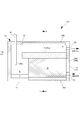
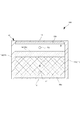
- FIG. 2 is a cross-sectional view taken along the line AA showing the vaporizer according to the first embodiment. It is sectional drawing which shows the vaporization apparatus which concerns on Embodiment 2.
- FIG. 2 is a cross-sectional view taken along the line AA showing the vaporizer according to the first embodiment. It is sectional drawing which shows the vaporization apparatus which concerns on Embodiment 2.
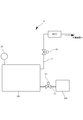
- the vaporization system Z supplies a material gas generated by vaporizing the liquid material Z by the vaporization apparatus 100 to a target device as a supply destination, and the target device is, for example, a semiconductor manufacturing process.
- the target device is, for example, a semiconductor manufacturing process.
- the chamber etc. which are used are mentioned, it is not limited to this.
- the vaporization system Z includes a vaporizer 100, an introduction path L ⁇ b> 1 for introducing the liquid material X into the vaporizer 100, and a lead-out path L ⁇ b> 2 for deriving the material gas from the vaporizer 100.
- the open / close valve V ⁇ b> 1 is connected to the introduction path L ⁇ b> 1, and one end on the upstream side is connected to the liquid material supply device 200.
- the on-off valve V2 and the flow rate control device MFC are connected to the lead-out path L2 in order from the upstream side, and one end on the downstream side is connected to the target device.
- a differential pressure type or thermal type mass flow controller can be used, and the flow rate of the material gas flowing in the lead-out path L2 can be controlled to a predetermined flow rate.
- the on-off valve V2 is not necessarily provided because it can be substituted by a control valve provided in the flow control device MFC.
- the vaporizer 100 includes a container 10 that stores the liquid material X, a holding member W that holds the liquid material X, and a liquid that heats the liquid material X held by the holding member W.
- a detection device 20 that detects the amount of X liquid. 2 and 3
- the liquid surface of the liquid material X is indicated by a one-dot chain line.
- the container 10 has a housing shape and is a horizontally long type.
- the container 10 is provided with an introduction port P1 connected to the introduction path L1 and a lead-out port P2 connected to the lead-out path L2.
- the introduction port P ⁇ b> 1 is provided in the lower part of the container 10 and is connected to the vaporization chamber S of the container 10.
- the outlet P2 is provided at the upper part of the container 10 and is connected to the vaporization chamber S of the container 10, specifically, the gas phase in which the material gas in the container 10 stays (upper side in FIG. 2). Yes.
- the introduction port P1 and the outlet port P2 are both arranged vertically with respect to the same side wall 11 of the container 10.
- the container 10 is provided with a partition wall 14 that extends the gas phase in the vaporization chamber S in the horizontal direction. That is, the partition wall 14 is provided to divide the gas phase into a plurality of parts.
- the partition wall 14 extends from the one side wall 11a between the introduction port P1 and the introduction port P2 toward the other side wall 11b facing the one side wall 11a, and does not reach the other side wall 11b. ing. Thereby, a gap is formed between the other side wall 11b and the partition wall 14, and the upper side and the lower side of the gas phase partitioned by the partition wall 14 are connected by this gap.
- the holding member W is installed in the lower part of the container 10. Specifically, it is installed adjacent to the inlet P ⁇ b> 1 in the container 10, and is filled between the bottom wall 12 and the partition wall 14.
- the holding member W is filled on the one side wall 11a side and is not filled on the other side wall 11b side.
- the holding member W is installed on the bottom wall 12 on the introduction port P1 side, and is not installed on the bottom wall 12 on the other side wall 11b side. Thereby, a region not filled with the holding member W is formed in the lower portion of the container 10.
- the holding member W has a large number of at least one or both of a gap or a cavity through which the liquid material X and a material gas obtained by vaporizing the liquid material X can pass, and can hold the liquid material X in the inside thereof. It does not matter whether the holding ability is high or low.
- a linear body, a net-like body, a fibrous body or a granular body (including a powder body) held in a predetermined shape, a porous body having a predetermined shape, or the like can be used as the holding member W.
- examples of holding the linear body in a predetermined shape include those in which the linear body is three-dimensionally coupled.
- Examples of holding the net-like body in a predetermined shape include those obtained by laminating and joining a plurality of net-like bodies.
- Examples of the net-like body include those obtained by molding a plate material into a net shape, and those obtained by combining wire rods into a net shape. , Or woven or knitted wire rods.
- Examples of the fibrous body held in a predetermined shape include those obtained by solidifying the fibrous body, those obtained by laminating a plurality of non-woven fabrics composed of fibrous bodies, and those obtained by laminating a plurality of woven fabrics and knitted fabrics comprising fibrous bodies. .
- Examples of the granular body held in a predetermined shape include those in which the granular bodies are combined and those in which the granular bodies are filled in a cartridge.
- Examples of the granular bodies include spheres and powders. These materials are preferably made of metal, and can be sintered and bonded if they are made of metal, and materials having high thermal conductivity can be selected. For example, it is preferable to use steel wool that is a metal fiber that can be easily filled in the container 10 or SUS316L that is stainless steel having excellent corrosion resistance.
- a non-porous material such as a metal processed into a honeycomb structure or the like to form a porous structure may be used.
- a material such as ceramic alumina or SiC is itself porous.
- a structure may be used.
- the area where the holding member 10 is not filled in the lower part of the container 10 is the storage area R. Accordingly, the storage region R is disposed so as to be adjacent to the holding member 40 in the horizontal direction. In addition, the storage region R is disposed on the opposite side of the holding member W from the introduction port P1 side. If comprised in this way, the liquid material X introduce
- the holding member W When the liquid material X is supplied into the container 10, as shown in FIGS. 2 and 3, the holding member W is sequentially filled with the liquid material X from the lower side and holds the liquid material X.
- the liquid material X that has flowed out without being held by the holding member W is stored in the storage region R.
- the holding capability of the holding member W when the holding capability of the holding member W is high, the area filled with the liquid material X of the holding member W increases. Conversely, when the holding capability of the holding member W is low, the area filled with the holding liquid material X decreases. Therefore, by grasping the holding ability of the holding member W in advance, the liquid amount of the liquid material X in the container 10 can be more accurately grasped from the liquid amount of the liquid material X stored in the storage region R. .
- the detection device 20 is a liquid level sensor, specifically, a contact-type liquid level sensor that detects the liquid level by bringing the sensor unit 20a into contact with the liquid material X.
- the liquid level sensor is installed by inserting the sensor unit 20 a from the insertion hole provided in the upper wall 13 of the container 10, and the sensor unit 20 a extends toward the storage region R.
- the liquid level sensor includes a resistance temperature detector such as a thermistor, and is configured to detect the liquid level by utilizing the fact that the heat dissipation constant differs between the liquid phase and the gas phase.
- the liquid heater 30a is provided in the lower part of the container 10 and is installed in a portion adjacent to the holding member W on the outer wall of the container 10.
- the liquid heater 30 a is separately installed on the bottom wall 12 and the one side wall 11 a that are the outer walls of the container 10. Thereby, the liquid material X hold
- the gas heater 30b is provided on the upper part of the container 10 and is installed on the partition wall 14 and the part in contact with the gas phase on the outer wall of the container 10.
- the gas heater 30 b is separately installed on the upper wall 13 and the partition wall 14 that are outer walls of the container 10.
- the partition wall 14 itself is a gas heater 30b.
- the material gas is heated by the gas heater 30b, and the material gas can be prevented from being cooled again and liquefied again.
- the gas heater 30b of the partition wall 14 also serves as the liquid heater 30a.
- each heater 30a, 30b installed in each outer wall of the container 10 is good also as another heater 30a, 30b, respectively, like this embodiment, and the heater 30a, 30a installed in the adjacent outer wall 30b may be integrated.
- the heaters 30a and 30b are provided on the other side wall 11b and both side walls 11c and 11d (see FIG. 3) that are interposed between the one side wall 11a and the other side wall 11b and face each other.
- the gas heater 30b may be provided on the other side wall 11b, and the heaters 30a and 30b may be provided on the side walls 11c and 11d.
- each heater 30a, 30b is provided so as to be embedded inside the outer wall of the container 10, but may be provided so as to be attached to the inner surface or the outer surface of the outer wall of the container 10, As long as heat is sufficiently transmitted to the container 10 and each heater 30a, 30b can play its role, it may be provided away from the outer wall.
- the storage region R in the container 10 becomes a region with a small amount of heat transfer away from the heaters 30a and 30b, and the liquid stored in the storage region R is stored. Material X is not actively vaporized.
- the holding area where the holding member W is installed in the container 10 is an area close to the liquid heater 30a and having a large amount of heat transfer, and the liquid material X held in the holding area is positively vaporized.
- the gas phase region in the container 10 is also close to the gas heater 30b and has a large amount of heat transfer, and the material gas staying in the gas phase region is positively heated.
- each heater 30a, 30b a cartridge heater, a heating wire heater, or a rubber heater can be used.
- the vaporization system Z includes a control device (not shown) that appropriately opens and closes the on-off valve V1 connected to the introduction path L1 and the on-off valve V2 connected to the lead-out path L2, depending on the situation. Based on the detection signal detected by the ten detection devices 20, the opening degree of the on-off valve V1 provided in the introduction path L1 is adjusted, and the supply amount of the liquid material X to the vaporizer 100 can be controlled. .
- the control device opens or closes the on-off valves V1 and V2 so that only the on-off valve V1 is opened, only the on-off valve V2 is opened, or both the on-off valves V1 and V2 are opened. It can be switched selectively.
- the liquid material X introduced from the inlet P1 of the container 10 in the vaporizer 100 once flows into the holding member W, and then the liquid material X released from the holding member W. Is stored in the storage region R, the excess liquid material X that is not held by the holding member W can be accurately detected in the storage region R. Then, if the amount of liquid stored in the storage region R is detected and the supply amount of the liquid material X supplied to the vaporizer 100 is controlled based on the detected liquid amount, the liquid material X in the container 10 is controlled. The amount of liquid can be kept constant, and emptying due to the decrease in the liquid material X in the container 10 and the inflow of the liquid material X into the outlet path L2 due to the increase in the liquid material X in the container 10 can be prevented. Can do.
- each heater 30a, 30b was installed apart from the storage area
- the liquid level can be detected more accurately, more specifically, the liquid level can be detected more accurately by the liquid level sensor.
- liquid material X is vaporized inside the holding member W, bubbles generated at the time of vaporization do not grow greatly, thereby suppressing the fluctuation of the liquid surface of the liquid material X stored in the storage region R. . Furthermore, since most of the liquid material X is vaporized in the holding member W, splashes that are generated when bubbles generated during the vaporization are blown off are retained in the holding member W and are prevented from being scattered to the gas phase side. it can.
- the holding member W is formed of a material having high thermal conductivity, the heat of the liquid heater 30a is transmitted to the holding member W, and not only the liquid material X that contacts the liquid heater 30a but also the holding member W is held.
- the liquid material X in contact with the member W is also vaporized, the heating contact area of the liquid material X is increased, and the heat exchange rate is improved.
- the partition wall 14 is provided between the outlet P2 and the holding member W, the bubbles generated during the vaporization of the liquid material X are bounced and scattered, and the splashes are blocked by the partition wall 14 and directly flow out from the outlet P2. Can be prevented.
- the material gas generated by the holding member W is heated by the gas heater 30b provided in the partition wall 14 so as to circulate from the storage region R side to the upper side of the partition wall 14 and lead out to the outlet P2. Reliquefaction associated with cooling is prevented.
- the vaporizer 100 stores a reference unit for determining whether or not the amount of liquid stored in the storage region R is abnormal, and the detection detected by the detection device 20.
- a liquid amount monitoring unit may be provided that includes a determination unit that determines whether the liquid amount is within the reference range and a warning unit that warns when the detected liquid amount is outside the reference range. With such a configuration, an abnormality in the amount of liquid in the container 10 can be quickly detected.
- the warning unit may warn by a display unit or a voice unit.
- the liquid amount monitoring unit may be provided as a part of the control device.
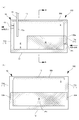
- the present embodiment is a modification of the vaporizer 100 according to the first embodiment.
- 4A is a cross-sectional view showing a state in which the vaporizer according to the present embodiment is viewed from the horizontal direction
- FIG. 4B is a cross-sectional view taken along line BB in FIG. 4A.
- the vaporizer 100 according to the present embodiment is different in configuration from the container 10 of the first embodiment in the following points.
- the partition wall 14 is not provided in the vaporization chamber S, whereby the upper side of the holding member W is in a gas phase.
- the gas heater 30b is installed so as to extend from the upper wall 13 to the side wall 11b.
- the liquid heater 30a is provided in the part adjacent to the holding member W upper part of side wall 11a, 11c, 11d so that only the upper part of the holding member W may be heated. .
- the lower part of the holding member W adjacent to the liquid material X stored in the storage region R is not actively heated, and bubbles are generated from the liquid material X held in the lower part of the holding member W. Since it becomes difficult, the fluctuation
- the inlet P1 and the outlet P2 are provided on different side walls 11. Specifically, the inlet P1 is provided in the one side wall 11a, and the outlet P2 is provided in the other side wall 11b. In this case, the outlet port P2 is disposed above the storage region R, and the liquid material X is not positively vaporized in the storage region R, so that bubbles due to bubbles are less likely to flow into the outlet port P2.
- the storage region R is provided between the holding member W and the side wall 11b farthest from the introduction port P1, but the side walls 11b, 11c, other than the side wall 11a provided with the introduction port P1.
- region R may be provided between any side wall 11b, 11c, 11d, and the storage area
- region R may be provided between two or more side walls.
- the liquid level sensor is used as the detection apparatus 20, it is not limited to this, If it can detect the liquid quantity of the liquid material X stored by the storage area
- a contact type sensor is used as the liquid level sensor, but a non-contact type sensor or a float sensor may be used.
- the mechanism has a movable part such as a float type, there is a possibility that particles are generated in the movable part.
- a viewing window is provided in the part corresponding to the storage area
- each heater 30a, 30b is installed in the outer wall adjacent to the storage area
- the heaters 30a and 30b may be installed on the outer wall adjacent to the storage region R. In this case, the liquid material X stored in the storage region R is heated to the extent that it does not vaporize and bubbles are generated.
- the liquid heater 30a is adjacent to the upper side of the holding member W to actively heat only the upper part of the holding member W.
- the liquid heater 30a is adjacent to the entire side of the holding member W.
- a temperature gradient may be provided so that the temperature increases from the lower side to the upper side of each liquid heater 30a.
- the liquid material X held on the upper part of the holding member W is positively heated, and the same effect as the vaporizer 100 according to the second embodiment can be obtained.
- the horizontally placed container 10 is used, but a vertically long container 10 may be used.
- the remaining amount of the liquid material in the container can be confirmed in the vaporization apparatus including the holding member that holds the liquid material introduced into the container.
Landscapes
- Engineering & Computer Science (AREA)
- Chemical & Material Sciences (AREA)
- Mechanical Engineering (AREA)
- General Engineering & Computer Science (AREA)
- Organic Chemistry (AREA)
- Chemical Kinetics & Catalysis (AREA)
- Feeding, Discharge, Calcimining, Fusing, And Gas-Generation Devices (AREA)
- Filling Or Discharging Of Gas Storage Vessels (AREA)
- Chemical Vapour Deposition (AREA)
Abstract
L'objectif de l'invention est de permettre de vérifier, dans un dispositif de vaporisation comprenant un élément de retenue qui retient un matériau liquide à introduire dans un récipient, la quantité restante du matériau liquide à l'intérieur du récipient. Le dispositif de vaporisation selon l'invention comprend : un récipient pourvu d'une ouverture d'introduction à travers laquelle un matériau liquide est introduit ; un élément de retenue qui retient le matériau liquide à introduire depuis l'ouverture d'introduction dans le récipient ; et une région de stockage qui est disposée à l'intérieur du récipient et qui stocke le matériau liquide qui s'est écoulé à partir de l'élément de retenue.
Priority Applications (1)
| Application Number | Priority Date | Filing Date | Title |
|---|---|---|---|
| JP2019512511A JP7129969B2 (ja) | 2017-04-13 | 2018-04-10 | 気化装置及び気化システム |
Applications Claiming Priority (2)
| Application Number | Priority Date | Filing Date | Title |
|---|---|---|---|
| JP2017080070 | 2017-04-13 | ||
| JP2017-080070 | 2017-04-13 |
Publications (1)
| Publication Number | Publication Date |
|---|---|
| WO2018190318A1 true WO2018190318A1 (fr) | 2018-10-18 |
Family
ID=63793179
Family Applications (1)
| Application Number | Title | Priority Date | Filing Date |
|---|---|---|---|
| PCT/JP2018/014991 Ceased WO2018190318A1 (fr) | 2017-04-13 | 2018-04-10 | Dispositif de vaporisation et système de vaporisation |
Country Status (2)
| Country | Link |
|---|---|
| JP (1) | JP7129969B2 (fr) |
| WO (1) | WO2018190318A1 (fr) |
Citations (5)
| Publication number | Priority date | Publication date | Assignee | Title |
|---|---|---|---|---|
| JPS4929145U (fr) * | 1972-05-25 | 1974-03-13 | ||
| JPH06226990A (ja) * | 1993-02-04 | 1994-08-16 | Canon Inc | インクタンクおよびインクジェット記録装置 |
| JP2004298769A (ja) * | 2003-03-31 | 2004-10-28 | Jgc Corp | 気相反応装置 |
| JP2005160903A (ja) * | 2003-12-05 | 2005-06-23 | Ngk Insulators Ltd | 滅菌装置 |
| JP2005166771A (ja) * | 2003-12-01 | 2005-06-23 | Japan Pionics Co Ltd | 液体cvd原料用の充填容器、液体cvd原料の充填容器、及びこれらを用いた気化供給方法 |
-
2018
- 2018-04-10 JP JP2019512511A patent/JP7129969B2/ja active Active
- 2018-04-10 WO PCT/JP2018/014991 patent/WO2018190318A1/fr not_active Ceased
Patent Citations (5)
| Publication number | Priority date | Publication date | Assignee | Title |
|---|---|---|---|---|
| JPS4929145U (fr) * | 1972-05-25 | 1974-03-13 | ||
| JPH06226990A (ja) * | 1993-02-04 | 1994-08-16 | Canon Inc | インクタンクおよびインクジェット記録装置 |
| JP2004298769A (ja) * | 2003-03-31 | 2004-10-28 | Jgc Corp | 気相反応装置 |
| JP2005166771A (ja) * | 2003-12-01 | 2005-06-23 | Japan Pionics Co Ltd | 液体cvd原料用の充填容器、液体cvd原料の充填容器、及びこれらを用いた気化供給方法 |
| JP2005160903A (ja) * | 2003-12-05 | 2005-06-23 | Ngk Insulators Ltd | 滅菌装置 |
Also Published As
| Publication number | Publication date |
|---|---|
| JP7129969B2 (ja) | 2022-09-02 |
| JPWO2018190318A1 (ja) | 2020-02-20 |
Similar Documents
| Publication | Publication Date | Title |
|---|---|---|
| TWI583817B (zh) | 氣化原料供給裝置、具備此的基板處理裝置及氣化原料供給方法 | |
| Duan et al. | Surface excess properties from energy transport measurements during water evaporation | |
| TWI482875B (zh) | 固定濃度蒸發之方法及使用該方法之裝置 | |
| TWI674330B (zh) | 流體控制裝置 | |
| JP2012064982A5 (fr) | ||
| JP2016211021A (ja) | 気化供給装置 | |
| KR20190140002A (ko) | 유체 제어 장치 | |
| KR102894024B1 (ko) | 기화 공급 장치 | |
| WO2018190318A1 (fr) | Dispositif de vaporisation et système de vaporisation | |
| US9914997B2 (en) | Method for supplying a process with an enriched carrier gas | |
| JP2022061803A (ja) | 気化装置、ガス供給装置及びガス供給装置の制御方法 | |
| JP2010540766A (ja) | 蒸気運搬システム | |
| CN101945711A (zh) | 蒸气输送系统 | |
| JP7148497B2 (ja) | 気化装置及び気化システム | |
| WO2020195349A1 (fr) | Vaporisateur | |
| TWI658856B (zh) | 液體材料氣化裝置、液體材料氣化系統 | |
| JP2013009834A (ja) | 輸液温調デバイスおよび輸液温調システム | |
| JP2016199327A (ja) | ウォーターサーバおよびその給水方法 | |
| US20250108351A1 (en) | Vaporizer and vaporizing system | |
| JP2017523606A (ja) | 流体化学物質送出を自動調整するための装置および方法 | |
| JP2020020036A (ja) | 気化器 | |
| JP5875024B2 (ja) | 過熱水蒸気発生装置及び過熱水蒸気発生方法 | |
| JP6350140B2 (ja) | 原料供給装置およびガラス母材の製造方法 | |
| TWM641337U (zh) | 氣體供應裝置 | |
| JP6715729B2 (ja) | ガス供給装置 |
Legal Events
| Date | Code | Title | Description |
|---|---|---|---|
| 121 | Ep: the epo has been informed by wipo that ep was designated in this application |
Ref document number: 18784143 Country of ref document: EP Kind code of ref document: A1 |
|
| ENP | Entry into the national phase |
Ref document number: 2019512511 Country of ref document: JP Kind code of ref document: A |
|
| NENP | Non-entry into the national phase |
Ref country code: DE |
|
| 122 | Ep: pct application non-entry in european phase |
Ref document number: 18784143 Country of ref document: EP Kind code of ref document: A1 |