WO2018190424A1 - 金属鋳塊の製造方法 - Google Patents
金属鋳塊の製造方法 Download PDFInfo
- Publication number
- WO2018190424A1 WO2018190424A1 PCT/JP2018/015555 JP2018015555W WO2018190424A1 WO 2018190424 A1 WO2018190424 A1 WO 2018190424A1 JP 2018015555 W JP2018015555 W JP 2018015555W WO 2018190424 A1 WO2018190424 A1 WO 2018190424A1
- Authority
- WO
- WIPO (PCT)
- Prior art keywords
- hearth
- molten metal
- irradiation line
- electron beam
- irradiation
- Prior art date
- Legal status (The legal status is an assumption and is not a legal conclusion. Google has not performed a legal analysis and makes no representation as to the accuracy of the status listed.)
- Ceased
Links
Images
















Classifications
-
- B—PERFORMING OPERATIONS; TRANSPORTING
- B22—CASTING; POWDER METALLURGY
- B22D—CASTING OF METALS; CASTING OF OTHER SUBSTANCES BY THE SAME PROCESSES OR DEVICES
- B22D7/00—Casting ingots, e.g. from ferrous metals
- B22D7/005—Casting ingots, e.g. from ferrous metals from non-ferrous metals
-
- B—PERFORMING OPERATIONS; TRANSPORTING
- B22—CASTING; POWDER METALLURGY
- B22D—CASTING OF METALS; CASTING OF OTHER SUBSTANCES BY THE SAME PROCESSES OR DEVICES
- B22D1/00—Treatment of fused masses in the ladle or the supply runners before casting
-
- B—PERFORMING OPERATIONS; TRANSPORTING
- B22—CASTING; POWDER METALLURGY
- B22D—CASTING OF METALS; CASTING OF OTHER SUBSTANCES BY THE SAME PROCESSES OR DEVICES
- B22D11/00—Continuous casting of metals, i.e. casting in indefinite lengths
- B22D11/001—Continuous casting of metals, i.e. casting in indefinite lengths of specific alloys
-
- B—PERFORMING OPERATIONS; TRANSPORTING
- B22—CASTING; POWDER METALLURGY
- B22D—CASTING OF METALS; CASTING OF OTHER SUBSTANCES BY THE SAME PROCESSES OR DEVICES
- B22D11/00—Continuous casting of metals, i.e. casting in indefinite lengths
- B22D11/04—Continuous casting of metals, i.e. casting in indefinite lengths into open-ended moulds
- B22D11/041—Continuous casting of metals, i.e. casting in indefinite lengths into open-ended moulds for vertical casting
-
- B—PERFORMING OPERATIONS; TRANSPORTING
- B22—CASTING; POWDER METALLURGY
- B22D—CASTING OF METALS; CASTING OF OTHER SUBSTANCES BY THE SAME PROCESSES OR DEVICES
- B22D11/00—Continuous casting of metals, i.e. casting in indefinite lengths
- B22D11/10—Supplying or treating molten metal
- B22D11/103—Distributing the molten metal, e.g. using runners, floats, distributors
-
- B—PERFORMING OPERATIONS; TRANSPORTING
- B22—CASTING; POWDER METALLURGY
- B22D—CASTING OF METALS; CASTING OF OTHER SUBSTANCES BY THE SAME PROCESSES OR DEVICES
- B22D11/00—Continuous casting of metals, i.e. casting in indefinite lengths
- B22D11/10—Supplying or treating molten metal
- B22D11/11—Treating the molten metal
-
- B—PERFORMING OPERATIONS; TRANSPORTING
- B22—CASTING; POWDER METALLURGY
- B22D—CASTING OF METALS; CASTING OF OTHER SUBSTANCES BY THE SAME PROCESSES OR DEVICES
- B22D11/00—Continuous casting of metals, i.e. casting in indefinite lengths
- B22D11/10—Supplying or treating molten metal
- B22D11/11—Treating the molten metal
- B22D11/116—Refining the metal
-
- B—PERFORMING OPERATIONS; TRANSPORTING
- B22—CASTING; POWDER METALLURGY
- B22D—CASTING OF METALS; CASTING OF OTHER SUBSTANCES BY THE SAME PROCESSES OR DEVICES
- B22D21/00—Casting non-ferrous metals or metallic compounds so far as their metallurgical properties are of importance for the casting procedure; Selection of compositions therefor
- B22D21/002—Castings of light metals
- B22D21/005—Castings of light metals with high melting point, e.g. Be 1280 degrees C, Ti 1725 degrees C
-
- B—PERFORMING OPERATIONS; TRANSPORTING
- B22—CASTING; POWDER METALLURGY
- B22D—CASTING OF METALS; CASTING OF OTHER SUBSTANCES BY THE SAME PROCESSES OR DEVICES
- B22D21/00—Casting non-ferrous metals or metallic compounds so far as their metallurgical properties are of importance for the casting procedure; Selection of compositions therefor
- B22D21/02—Casting exceedingly oxidisable non-ferrous metals, e.g. in inert atmosphere
- B22D21/022—Casting heavy metals, with exceedingly high melting points, i.e. more than 1600 degrees C, e.g. W 3380 degrees C, Ta 3000 degrees C, Mo 2620 degrees C, Zr 1860 degrees C, Cr 1765 degrees C, V 1715 degrees C
-
- B—PERFORMING OPERATIONS; TRANSPORTING
- B22—CASTING; POWDER METALLURGY
- B22D—CASTING OF METALS; CASTING OF OTHER SUBSTANCES BY THE SAME PROCESSES OR DEVICES
- B22D21/00—Casting non-ferrous metals or metallic compounds so far as their metallurgical properties are of importance for the casting procedure; Selection of compositions therefor
- B22D21/06—Casting non-ferrous metals with a high melting point, e.g. metallic carbides
-
- B—PERFORMING OPERATIONS; TRANSPORTING
- B22—CASTING; POWDER METALLURGY
- B22D—CASTING OF METALS; CASTING OF OTHER SUBSTANCES BY THE SAME PROCESSES OR DEVICES
- B22D27/00—Treating the metal in the mould while it is molten or ductile ; Pressure or vacuum casting
- B22D27/02—Use of electric or magnetic effects
-
- B—PERFORMING OPERATIONS; TRANSPORTING
- B22—CASTING; POWDER METALLURGY
- B22D—CASTING OF METALS; CASTING OF OTHER SUBSTANCES BY THE SAME PROCESSES OR DEVICES
- B22D35/00—Equipment for conveying molten metal into beds or moulds
- B22D35/04—Equipment for conveying molten metal into beds or moulds into moulds, e.g. base plates, runners
-
- B—PERFORMING OPERATIONS; TRANSPORTING
- B22—CASTING; POWDER METALLURGY
- B22D—CASTING OF METALS; CASTING OF OTHER SUBSTANCES BY THE SAME PROCESSES OR DEVICES
- B22D41/00—Casting melt-holding vessels, e.g. ladles, tundishes, cups or the like
- B22D41/005—Casting melt-holding vessels, e.g. ladles, tundishes, cups or the like with heating or cooling means
- B22D41/01—Heating means
- B22D41/015—Heating means with external heating, i.e. the heat source not being a part of the ladle
-
- C—CHEMISTRY; METALLURGY
- C21—METALLURGY OF IRON
- C21D—MODIFYING THE PHYSICAL STRUCTURE OF FERROUS METALS; GENERAL DEVICES FOR HEAT TREATMENT OF FERROUS OR NON-FERROUS METALS OR ALLOYS; MAKING METAL MALLEABLE, e.g. BY DECARBURISATION OR TEMPERING
- C21D9/00—Heat treatment, e.g. annealing, hardening, quenching or tempering, adapted for particular articles; Furnaces therefor
- C21D9/70—Furnaces for ingots, i.e. soaking pits
-
- C—CHEMISTRY; METALLURGY
- C22—METALLURGY; FERROUS OR NON-FERROUS ALLOYS; TREATMENT OF ALLOYS OR NON-FERROUS METALS
- C22B—PRODUCTION AND REFINING OF METALS; PRETREATMENT OF RAW MATERIALS
- C22B34/00—Obtaining refractory metals
- C22B34/10—Obtaining titanium, zirconium or hafnium
- C22B34/12—Obtaining titanium or titanium compounds from ores or scrap by metallurgical processing; preparation of titanium compounds from other titanium compounds see C01G23/00 - C01G23/08
- C22B34/1295—Refining, melting, remelting, working up of titanium
-
- C—CHEMISTRY; METALLURGY
- C22—METALLURGY; FERROUS OR NON-FERROUS ALLOYS; TREATMENT OF ALLOYS OR NON-FERROUS METALS
- C22B—PRODUCTION AND REFINING OF METALS; PRETREATMENT OF RAW MATERIALS
- C22B9/00—General processes of refining or remelting of metals; Apparatus for electroslag or arc remelting of metals
- C22B9/16—Remelting metals
- C22B9/22—Remelting metals with heating by wave energy or particle radiation
-
- C—CHEMISTRY; METALLURGY
- C22—METALLURGY; FERROUS OR NON-FERROUS ALLOYS; TREATMENT OF ALLOYS OR NON-FERROUS METALS
- C22B—PRODUCTION AND REFINING OF METALS; PRETREATMENT OF RAW MATERIALS
- C22B9/00—General processes of refining or remelting of metals; Apparatus for electroslag or arc remelting of metals
- C22B9/16—Remelting metals
- C22B9/22—Remelting metals with heating by wave energy or particle radiation
- C22B9/228—Remelting metals with heating by wave energy or particle radiation by particle radiation, e.g. electron beams
-
- C—CHEMISTRY; METALLURGY
- C22—METALLURGY; FERROUS OR NON-FERROUS ALLOYS; TREATMENT OF ALLOYS OR NON-FERROUS METALS
- C22C—ALLOYS
- C22C14/00—Alloys based on titanium
-
- F—MECHANICAL ENGINEERING; LIGHTING; HEATING; WEAPONS; BLASTING
- F27—FURNACES; KILNS; OVENS; RETORTS
- F27B—FURNACES, KILNS, OVENS OR RETORTS IN GENERAL; OPEN SINTERING OR LIKE APPARATUS
- F27B3/00—Hearth-type furnaces, e.g. of reverberatory type; Electric arc furnaces ; Tank furnaces
- F27B3/02—Hearth-type furnaces, e.g. of reverberatory type; Electric arc furnaces ; Tank furnaces of single-chamber fixed-hearth type
-
- F—MECHANICAL ENGINEERING; LIGHTING; HEATING; WEAPONS; BLASTING
- F27—FURNACES; KILNS; OVENS; RETORTS
- F27B—FURNACES, KILNS, OVENS OR RETORTS IN GENERAL; OPEN SINTERING OR LIKE APPARATUS
- F27B3/00—Hearth-type furnaces, e.g. of reverberatory type; Electric arc furnaces ; Tank furnaces
- F27B3/04—Hearth-type furnaces, e.g. of reverberatory type; Electric arc furnaces ; Tank furnaces of multiple-hearth type; of multiple-chamber type; Combinations of hearth-type furnaces
- F27B3/045—Multiple chambers, e.g. one of which is used for charging
-
- F—MECHANICAL ENGINEERING; LIGHTING; HEATING; WEAPONS; BLASTING
- F27—FURNACES; KILNS; OVENS; RETORTS
- F27B—FURNACES, KILNS, OVENS OR RETORTS IN GENERAL; OPEN SINTERING OR LIKE APPARATUS
- F27B3/00—Hearth-type furnaces, e.g. of reverberatory type; Electric arc furnaces ; Tank furnaces
- F27B3/08—Hearth-type furnaces, e.g. of reverberatory type; Electric arc furnaces ; Tank furnaces heated electrically, with or without any other source of heat
-
- F—MECHANICAL ENGINEERING; LIGHTING; HEATING; WEAPONS; BLASTING
- F27—FURNACES; KILNS; OVENS; RETORTS
- F27B—FURNACES, KILNS, OVENS OR RETORTS IN GENERAL; OPEN SINTERING OR LIKE APPARATUS
- F27B3/00—Hearth-type furnaces, e.g. of reverberatory type; Electric arc furnaces ; Tank furnaces
- F27B3/10—Details, accessories or equipment, e.g. dust-collectors, specially adapted for hearth-type furnaces
- F27B3/20—Arrangements of heating devices
-
- F—MECHANICAL ENGINEERING; LIGHTING; HEATING; WEAPONS; BLASTING
- F27—FURNACES; KILNS; OVENS; RETORTS
- F27D—DETAILS OR ACCESSORIES OF FURNACES, KILNS, OVENS OR RETORTS, IN SO FAR AS THEY ARE OF KINDS OCCURRING IN MORE THAN ONE KIND OF FURNACE
- F27D99/00—Subject matter not provided for in other groups of this subclass
- F27D99/0001—Heating elements or systems
- F27D99/0006—Electric heating elements or system
-
- F—MECHANICAL ENGINEERING; LIGHTING; HEATING; WEAPONS; BLASTING
- F27—FURNACES; KILNS; OVENS; RETORTS
- F27D—DETAILS OR ACCESSORIES OF FURNACES, KILNS, OVENS OR RETORTS, IN SO FAR AS THEY ARE OF KINDS OCCURRING IN MORE THAN ONE KIND OF FURNACE
- F27D99/00—Subject matter not provided for in other groups of this subclass
- F27D99/0001—Heating elements or systems
- F27D99/0006—Electric heating elements or system
- F27D2099/003—Bombardment heating, e.g. with ions or electrons
Definitions
- the present invention relates to a method for producing a metal ingot in which a metal raw material is melted by an electron beam melting method.
- Ingots such as pure titanium and titanium alloys are manufactured by melting titanium raw materials such as sponge titanium or scrap.
- Examples of the technique for melting a metal raw material such as a titanium raw material include a vacuum arc melting method, a plasma arc melting method, and an electron beam melting method.
- the raw material is melted by irradiating the solid raw material with an electron beam in an electron beam melting furnace (hereinafter referred to as “EB furnace”).
- EB furnace electron beam melting furnace
- the melting of the raw material by the electron beam irradiation in the EB furnace is performed in a vacuum chamber.
- Molten titanium (hereinafter also referred to as “molten metal”), which is a melted raw material, is refined in hearth and then solidified in a mold (mold) to form a titanium ingot.
- the irradiation position of the electron beam which is a heat source, can be accurately controlled by electromagnetic force, so that heat can be sufficiently supplied to the molten metal near the mold. For this reason, an ingot can be manufactured without deteriorating the surface quality.
- An EB furnace generally includes a raw material supply unit that supplies a raw material such as sponge titanium, one or a plurality of electron guns for melting the supplied raw material, and a hearth (for example, A water-cooled copper hearth) and a mold for cooling the molten titanium poured from the hearth to form an ingot.
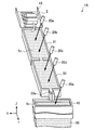
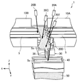
- EB furnaces are roughly classified into two types according to the difference in Haas configuration. Specifically, the EB furnace includes an EB furnace 1A having a melting hearth 31 and a refining hearth 33 as shown in FIG. 1, and an EB furnace 1B having only a refining hearth 30 as shown in FIG.
- the EB furnace 1A shown in FIG. 1 includes a raw material supply unit 10, electron guns 20a to 20e, a melting hearth 31, a refining hearth 33, and a mold 40.
- a raw material supply unit 10 electron guns 20a to 20e
- a melting hearth 31 a melting hearth 31
- a refining hearth 33 a mold 40.
- the said raw material is melt
- the temperature of the molten metal 5c is maintained or raised by irradiating the molten metal 5c with an electron beam by the electron guns 20c and 20d. Thereby, the impurities contained in the molten metal 5c are removed, and the molten metal 5c is refined. Thereafter, the refined molten metal 5 c is poured into the mold 40 from the lip portion 33 a provided at the end of the refined hearth 33. In the mold 40, the molten metal 5 c is solidified to produce the ingot 50.
- the hearth made up of the melting hearth 31 and the refining hearth 33 as shown in FIG. 1 is also called a long hearth.
- the EB furnace 1B shown in FIG. 2 includes raw material supply units 10A and 10B, electron guns 20A to 20D, a refining hearth 30, and a mold 40.
- the hearth consisting only of the refining hearth 30 is also referred to as a short hearth as compared to the long hearth shown in FIG.
- the solid raw material 5 placed on the raw material supply units 10A and 10B was melted by directly irradiating the electron beam with the electron guns 20A and 20B.
- the raw material 5 is dripped at the molten metal 5c of the refining hearth 30 from the raw material supply parts 10A and 10B.
- the melting hearth 31 shown in FIG. 1 can be omitted. Further, in the refining hearth 30, the temperature of the molten metal 5c is maintained or raised by irradiating the entire surface of the molten metal 5c with an electron beam by the electron gun 20C. Thereby, the impurities contained in the molten metal 5c are removed, and the molten metal 5c is refined. Thereafter, the refined molten metal 5 c is poured into the mold 40 from the lip portion 36 provided at the end of the refined hearth 30, and the ingot 50 is manufactured.
- Impurities are mainly mixed in the raw material, HDI (High Density Inclusion) and LDI (Low Density). Inclusion).
- HDI is an impurity mainly composed of tungsten, for example, and the specific gravity of HDI is larger than the specific gravity of molten titanium.
- LDI is an impurity mainly composed of titanium nitride or the like. Since the inside of LDI is porous, the specific gravity of LDI is smaller than the specific gravity of molten titanium.
- a solidified layer is formed by solidifying molten titanium in contact with the hearth.
- This solidified layer is called a skull.
- HDI has a high specific gravity, so it settles in the molten metal (molten titanium) in the hearth and is fixed and captured on the surface of the skull, so it is unlikely to be mixed into the ingot.
- LDI has a specific gravity smaller than that of molten titanium, most of LDI floats on the surface of the molten metal in the hearth. LDI is dissolved in the molten metal by diffusing nitrogen while floating on the molten metal surface.
- the residence time of the molten metal in the long hearth can be prolonged, so that impurities such as LDI are easily dissolved in the molten metal compared to the case where the short hearth is used.
- the short hearth shown in FIG. 2 since the residence time of the molten metal in the short hearth is shorter than that of the long hearth, the possibility that the impurities are not dissolved in the molten metal is higher than that of the long hearth.
- LDI having a high nitrogen concentration has a high melting point, the possibility of being dissolved in the molten metal within a normal operation residence time is extremely low.
- an electron beam is scanned on the surface of the molten metal in the hearth in the direction opposite to the flow direction of the molten metal into the mold, and the average temperature of the molten metal in the region adjacent to the molten metal outlet in the hearth Disclosed is an electron beam melting method for titanium metal that has a melting point of not less than.
- an electron beam melting method for titanium metal that has a melting point of not less than.
- impurities contained in the molten metal in the hearth in particular, LDI floating on the surface of the molten metal 5c may flow out of the hearth into the mold and be mixed into the ingot formed by the mold. Accordingly, there has been a demand for a method for manufacturing a metal ingot that can suppress the entry of impurities such as LDI from the hearth into the mold, thereby preventing the impurities from entering the ingot.
- the present invention has been made in view of the above problems, and an object of the present invention is a novel and improved method capable of suppressing impurities contained in the molten metal in the hearth from being mixed into the ingot. It is providing the manufacturing method of a metal ingot.
- an electron beam melting furnace including an electron gun capable of controlling an irradiation position of an electron beam and a hearth for storing a molten metal raw material is used.
- the lip portion In the downstream region between the upstream region supplied with the first side wall and the first side wall, the lip portion is closed, and two end portions are positioned in the vicinity of the side wall of the hearth.
- the irradiation line is arranged so that the irradiation line is irradiated with a first electron beam on the surface of the molten metal, and the irradiation line is irradiated with the first electron beam.
- the surface temperature (T2) of the molten metal in the line is made higher than the average surface temperature (T0) of the entire surface of the molten metal in the hearth, and the first side wall from the irradiation line in the surface layer of the molten metal
- T2 The surface temperature of the molten metal in the line is made higher than the average surface temperature (T0) of the entire surface of the molten metal in the hearth, and the first side wall from the irradiation line in the surface layer of the molten metal
- the surface of the molten metal in the hearth is irradiated with the electron beam to the irradiation line as described above, thereby preventing the impurities from flowing out from the hearth into the mold, and the impurities are mixed into the ingot. Can be prevented.
- the two end portions of the irradiation line are located in the vicinity of the first side wall.
- the two ends of the irradiation line are located in a region where the distance from the inner surface of the side wall or the inner surface of the side wall is 5 mm or less.
- the molten metal flow may be a flow that reaches from the irradiation line to a side wall extending substantially vertically from the first side wall to the upstream side of the hearth side wall.
- the projection line may protrude from the lip portion side toward the upstream side.
- the irradiation line may have a V shape or an arc shape having a diameter at least equal to or larger than the opening width of the lip portion.
- the irradiation line includes a first straight portion along the first side wall between the two end portions, and a second straight portion extending substantially perpendicularly from the first straight portion toward the upstream. It may be T-shaped.
- the irradiation line may have a linear shape along the first side wall between the two end portions.
- the molten metal stream flows from the irradiation line to the upstream, and from the pair of side walls of the hearth that extends from the first side wall to the upstream side substantially vertically and faces each other toward the center. There may be.
- the projection line may protrude from the upstream toward the lip portion.
- the irradiation line includes a first straight portion along the first side wall between the two end portions, and the two end portions of the first straight portion, and the first of the side walls of the hearth.
- a U-shape may be used, which includes a second straight line portion and a third straight line portion that extend substantially vertically from one side wall toward the upstream side and extend along the opposite side walls.
- the second electron beam may be irradiated to the stagnation position of the molten metal flow generated by irradiating the irradiation line with the first electron beam.
- the irradiation line may be irradiated with the plurality of first electron beams using a plurality of electron guns so that the irradiation trajectories of the first electron beam intersect or overlap each other on the surface of the molten metal. Good.
- the hearth consists of only one refining hearth, melts the metal raw material in the raw material supply unit, drops the dissolved metal raw material into the hearth from the raw material supply unit, and in the molten metal in the refining hearth
- the metal raw material may be refined.
- the hearth is a multiple-stage hearth that is continuously arranged by combining a plurality of divided hearts, and each of the divided hearts has the two end portions so as to block the lip portion in the downstream region. May irradiate the surface of the molten metal with the first electron beam to the irradiation line arranged so as to be positioned in the vicinity of the side wall of the divided hearth.
- the metal raw material may contain 50% by mass or more of titanium element.
- FIG. 5 is a partial cross-sectional view taken along a line II in FIG. 4.
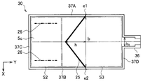
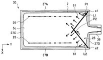
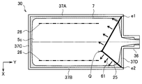
- FIG. 1 It is a top view which shows an example of the irradiation line which concerns on the same embodiment. It is a modification of the irradiation line which concerns on the same embodiment, Comprising: It is a top view which shows a V-shaped irradiation locus
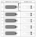
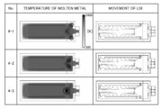
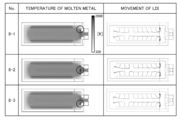
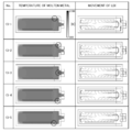
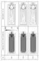
- FIG. 6 is an explanatory diagram illustrating a simulation result according to the first embodiment.
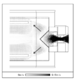
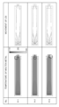
- 3 is a streamline diagram showing the flow of molten metal according to Example 1.
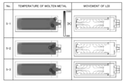
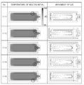
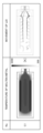
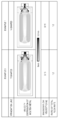
- FIG. FIG. 10 is an explanatory diagram illustrating a simulation result according to the second embodiment. It is explanatory drawing which shows the simulation result which concerns on Example 3.
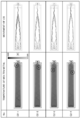
- FIG. It is explanatory drawing which shows the simulation result which concerns on Example 4.
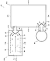
- FIG. 10 is an explanatory diagram showing an irradiation line of Example 5. It is explanatory drawing which shows the simulation result which concerns on Example 5.
- FIG. It is explanatory drawing which shows the irradiation line of Example 6.
- FIG. It is explanatory drawing which shows the simulation result which concerns on Example 6.
- FIG. 10 is an explanatory diagram showing simulation results according to Example 7.
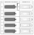
- FIG. 10 is an explanatory diagram showing simulation results according to Example 8. It is explanatory drawing which shows the simulation result which concerns on Example 9.
- FIG. It is explanatory drawing which shows the simulation result which concerns on Example 10.
- FIG. It is explanatory drawing which shows the simulation result which concerns on Example 11.
- FIG. It is explanatory drawing which shows the simulation result which concerns on Example 12.
- FIG. It is explanatory drawing which shows the irradiation line of the comparative example 2.
- FIG. 3 is a schematic diagram showing a configuration of an electron beam melting furnace 1 (hereinafter referred to as an EB furnace 1) according to the present embodiment.
- the EB furnace 1 includes a pair of raw material supply units 10A and 10B (hereinafter sometimes collectively referred to as “raw material supply unit 10”) and a plurality of electron guns 20A to 20E (hereinafter “ And a refining hearth 30 and a mold 40.
- the EB furnace 1 according to the present embodiment includes only one refining hearth 30 as a hearth, and this hearth structure is referred to as a short hearth.
- the method for producing a metal ingot of the present invention can be suitably applied to a short hearth EB furnace 1 as shown in FIG. 3, but can also be applied to a long hearth EB furnace 1A as shown in FIG. is there.
- the refining hearth 30 (hereinafter referred to as “hearth 30”) is an impurity contained in the molten metal 5c by refining the molten metal 5c while storing the molten metal 5c of the metal raw material 5 (hereinafter referred to as “raw material 5”). It is an apparatus for removing.
- the hearth 30 according to the present embodiment is composed of, for example, a water-cooled copper hearth having a rectangular shape.
- a lip portion 36 is provided on the side wall at one end of the longitudinal direction (Y direction) of the hearth 30. The lip portion 36 is an outlet for allowing the molten metal 5 c in the hearth 30 to flow out into the mold 40.
- the mold 40 is an apparatus for producing a metal ingot 50 (for example, an ingot of titanium or a titanium alloy) by cooling and solidifying the molten metal 5c of the raw material 5.
- the mold 40 is constituted by, for example, a water-cooled copper mold having a rectangular cylindrical shape.
- the mold 40 is disposed below the lip portion 36 of the hearth 30 and cools the molten metal 5 c poured from the upper hearth 30. As a result, the molten metal 5 c in the mold 40 is gradually solidified toward the lower side of the mold 40 to form a solid ingot 50.
- the raw material supply unit 10 is an apparatus for supplying the raw material 5 to the hearth 30.
- the raw material 5 is, for example, a titanium raw material such as sponge titanium or scrap.
- a pair of raw material supply units 10 ⁇ / b> A and 10 ⁇ / b> B is provided above the pair of long side walls of the hearth 30.
- a solid material 5 conveyed from the outside is placed on the material supply units 10A and 10B, and the electron beam is irradiated from the electron guns 20A and 20B to the material 5.
- the raw material supply unit 10 irradiates the solid raw material 5 with the electron beam, thereby melting the raw material 5 and dissolving the raw material 5.
- (Molded metal) is dropped from the inner edge of the raw material supply unit 10 to the molten metal 5 c in the hearth 30. That is, after the raw material 5 is previously melted outside the hearth 30, the molten metal is dropped onto the molten metal 5 c in the hearth 30 to supply the raw material 5 to the hearth 30.
- the dripping line showing the position where molten metal is dripped with respect to the surface of the molten metal 5c in the hearth 30 from the raw material supply part 10 corresponds to the supply line 26 (refer FIG. 4) mentioned later.
- the supply method of the raw material 5 is not limited to the example of the said dripping.
- the solid raw material 5 may be supplied as it is from the raw material supply unit 10 to the molten metal 5 c in the hearth 30.
- the charged solid raw material 5 is melted in the hot molten metal 5c and added to the molten metal 5c.
- a charging line indicating a position where the solid raw material 5 is charged into the molten metal 5c in the hearth 30 corresponds to a supply line 26 (see FIG. 4) described later.
- the electron gun 20 irradiates the raw material 5 or the molten metal 5c with an electron beam in order to execute the electron beam melting method.
- the EB furnace 1 includes, for example, electron guns 20 ⁇ / b> A and 20 ⁇ / b> B for melting a solid raw material 5 supplied to the raw material supply unit 10, and a molten metal 5 c in the hearth 30.
- An electron gun 20C for keeping heat, an electron gun 20D for heating the molten metal 5c in the upper part of the mold 40, and an electron gun 20E for suppressing the outflow of impurities from the hearth 30 are provided.
- Each of the electron guns 20A to 20E can control the irradiation position of the electron beam. Therefore, the electron guns 20 ⁇ / b> C and 20 ⁇ / b> E can irradiate an electron beam to a desired position on the surface of the molten metal 5 c in the hearth 30.
- the electron guns 20 ⁇ / b> A and 20 ⁇ / b> B heat and melt the raw material 5 by irradiating the solid raw material 5 placed on the raw material supply unit 10 with an electron beam.
- the electron gun 20C irradiates the surface of the molten metal 5c in the hearth 30 with an electron beam over a wide range, thereby heating the molten metal 5c and keeping it at a predetermined temperature.
- the electron gun 20D irradiates the surface of the molten metal 5c in the mold 40 with an electron beam, thereby heating the upper molten metal 5c in the mold 40 to a predetermined temperature so that the molten metal 5c in the upper part does not solidify. Hold.
- the electron gun 20E irradiates the electron beam intensively to the irradiation line 25 (see FIG. 4) on the surface of the molten metal 5c in the hearth 30 in order to prevent impurities from flowing out from the hearth 30 to the mold 40.
- the electron gun 20E is used to irradiate the electron beam intensively (line irradiation) to the irradiation line 25 on the surface of the molten metal 5c, thereby preventing the outflow of impurities.
- an electron gun 20E for line irradiation is provided separately from the other electron guns 20A to 20D.
- the raw material 5 is melted by the other electron guns 20A to 20D, and while the molten metal 5c is kept warm, it is possible to continue the line irradiation by the electron gun 20E at the same time. A decrease in surface temperature can be prevented.
- the present invention is not limited to such an example.
- one or more of the existing electron guns 20A and 20B for melting raw materials or the electron guns 20C and 20D for keeping molten metal are used without installing an additional electron gun 20E for line irradiation. It is also possible to irradiate the irradiation line 25 with an electron beam. As a result, the number of electron guns installed in the EB furnace 1 can be reduced, equipment costs can be reduced, and existing electron guns can be used effectively.
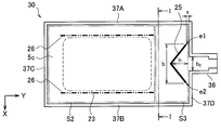
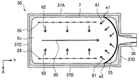
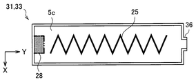
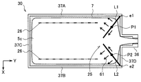
- FIG. 4 is a plan view showing an example of the irradiation line 25 and the supply line 26 in the hearth 30 according to the present embodiment.
- FIG. 5 is a partial cross-sectional view taken along the line II of FIG.
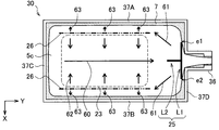
- FIG. 6 is a plan view showing an example of a molten metal flow formed when an electron beam is irradiated along an irradiation line by the method for manufacturing a metal ingot according to the present embodiment.
- the plan views of FIGS. 4 and 6 correspond to the hearth 30 of the electron beam melting furnace 1 of FIG.
- the purpose of the method for producing a metal ingot according to the present embodiment is to produce impurities contained in the molten metal (molten metal 5c) in which the solid raw material 5 is melted when the metal ingot 50 such as pure titanium or titanium alloy is produced. However, it is in suppressing flowing into the mold 40 from the hearth 30.
- a titanium raw material is used as a metal raw material, and among impurities contained in the titanium raw material, LDI having a specific gravity smaller than that of a molten titanium (molten titanium) is titanium or
- the problem to be solved is to prevent the titanium alloy ingot 50 from being mixed.
- the short hearth electron beam melting furnace 1 shown in FIG. 3 will be described.
- the present invention is not limited to this example, and the long hearth electron beam melting furnace shown in FIG. The present invention can also be applied to the furnace 1A.
- the raw material 5 is supplied to the supply line 26 adjacent to the long side walls 37 ⁇ / b> A and 37 ⁇ / b> B of the hearth 30. Is supplied to the molten metal 5 c in the hearth 30. The surface of the molten metal 5 c stored in the hearth 30 is irradiated with an electron beam onto the irradiation line 25 arranged so as to close the lip portion 36.
- the supply line 26 is a virtual line representing a position where the raw material 5 is supplied from the outside of the hearth 30 to the molten metal 5 c in the hearth 30.
- the supply line 26 is arranged along the inner side surfaces of the side walls 37A and 37B of the hearth 30 on the surface of the molten metal 5c.
- the melted raw material 5 is dropped onto the hearth 30 from the inner edge portion of the raw material supply unit 10 disposed above the long side walls 37 ⁇ / b> A and 37 ⁇ / b> B of the hearth 30. .
- the supply line 26 is located on the surface of the molten metal 5c in the hearth 30 below the inner edge of the raw material supply unit 10 and extends along the inner surfaces of the side walls 37A and 37B.
- the supply line 26 may not be a strict straight line along the inner surface of the side walls 37A, 37B, and 37C of the hearth 30.
- the supply line 26 may be a broken line, dotted line, curved line, wavy line, zigzag, It may be a double line shape, a band shape, a broken line shape, or the like.
- the irradiation line 25 (corresponding to the “irradiation line” of the present invention) is concentrated with an electron beam (corresponding to the “first electron beam” of the present invention) on the surface of the molten metal 5 c in the hearth 30. It is a virtual line showing the locus of the position irradiated to.
- the irradiation line 25 is arrange
- the two ends e1 and e2 of the irradiation line 25 are located in the vicinity of the side walls 37A, 37B, 37C, and 37D (hereinafter, may be collectively referred to as “sidewall 37”) of the hearth 30.
- the irradiation line 25 may not be strictly linear, and may be, for example, a broken line, a dotted line, a curved line, a wavy line, a zigzag shape, a double line shape, a belt shape, a broken line shape, or the like.
- the rectangular hearth 30 has four side walls 37A, 37B, 37C, and 37D.
- the pair of side walls 37 ⁇ / b> A and 37 ⁇ / b> B opposite to each other in the X direction constitute a pair of long sides of the hearth 30 and are parallel to the longitudinal direction (Y direction) of the hearth 30. That is, the side walls 37 ⁇ / b> A and 37 ⁇ / b> B extend substantially vertically from the side wall 37 ⁇ / b> D provided with the lip portion 36 toward the upstream.
- the pair of side walls 37 ⁇ / b> C and 37 ⁇ / b> D opposed to each other in the Y direction constitute a pair of short sides of the hearth 30 and are parallel to the width direction (X direction) of the hearth 30.
- substantially vertical is derived from the fact that a commonly used hearth has a rectangular shape, and a certain side wall and a side wall adjacent to the side wall intersect substantially vertically. That is, “substantially vertical” does not indicate strict verticality, and an error within a range that can generally be used as a hearth is allowed. The allowable angle error from vertical is, for example, within 5 °.
- a lip portion 36 for allowing the molten metal 5c in the hearth 30 to flow out into the mold 40 is provided on one side wall 37D of the short side.
- the lip portion 36 is not provided on the other three side walls 37A, 37B, and 37C other than the side wall 37D. Therefore, the side wall 37D corresponds to a “first side wall” in which a lip portion is provided, and the side walls 37A, 37B, and 37C correspond to “a side wall in which no lip portion is provided”.
- two linear supply lines 26 along the side walls 37 ⁇ / b> A and 37 ⁇ / b> B are arranged on the surface of the molten metal 5 c of the hearth 30.
- the irradiation line 25 is disposed on the downstream side of the supply line 26 in the longitudinal direction (Y direction) of the hearth 30 so as to close the lip portion 36.
- the region that includes the supply line 26 and does not contact the lip portion 36 is defined as the upstream region S2.
- a region between the upstream region S2 and the side wall 37D provided with the lip portion 36 is defined as a downstream region S3.
- the region in the hearth 30 will be described by dividing it into an upstream region S2 and a downstream region S3 by a straight line connecting the end points on the lip portion 36 side of the two supply lines 26.
- the irradiation line 25 is arranged in the downstream region S3.
- the two ends e1 and e2 of the irradiation line 25 are located in the vicinity of the side walls 37A, 37B, 37C, and 37D of the hearth 30.
- the end portions e1 and e2 are located in the vicinity of the side wall 37D.
- the end portions e1 and e2 are positioned in the vicinity of the side wall 37.
- the end portions e1 and e2 are positioned in a region where the distance x from the inner side surface of the side wall 37 or the inner side surface of the side wall 37 is 5 mm or less.
- the first electron beam is irradiated on such a region.
- the solidified layer called the skull 7 which the molten metal 5c solidified is formed in the inner surface of the side wall 37 of the hearth 30 (refer FIG. 5, FIG. 6). Even if the skull 7 is formed in the vicinity of the side wall 37, there is no problem, and the skull 7 may be irradiated with the first electron beam.
- a special temperature gradient is formed on the surface of the molten metal 5c in the hearth 30 by irradiating the irradiation line 25 on the surface of the molten metal 5c intensively, and the flow of the molten metal 5c. To control.
- the temperature distribution on the surface of the molten metal 5c in the hearth 30 will be described.
- the electron beam in order to prevent the molten metal 5c in the hearth 30 from solidifying, for example, the electron beam is uniformly applied to the heat retaining irradiation region 23 that occupies a wide area of the surface of the molten metal 5c by the electron gun 20C.
- the molten metal 5c in the hearth 30 is kept warm.
- the entire molten metal 5c stored in the hearth 30 is heated by the irradiation of the electron beam for heat insulation, and the average surface temperature T0 (hereinafter referred to as “molten surface temperature T0”) of the entire surface of the molten metal 5c. )
- the molten metal surface temperature T0 is, for example, 1923 (melting point of titanium alloy) to 2323K, and preferably 1973 to 2273K.
- the solid raw material 5 is irradiated with an electron beam by the electron guns 20 ⁇ / b> A and 20 ⁇ / b> B to melt the raw material 5, and the dissolved high-temperature molten metal is placed in the hearth 30.
- the raw material 5 is supplied to the hearth 30 by dropping it at the position of the supply line 26 of the molten metal 5c. For this reason, many impurities such as LDI contained in the raw material 5 exist in the vicinity of the supply line 26 in the molten metal 5 c in the hearth 30.
- the surface temperature T1 of the molten metal 5c in the supply line 26 (hereinafter referred to as “raw material supply temperature T1”) is substantially the same as the temperature of the molten metal dropped from the raw material supply unit 10 to the hearth 30, and the surface of the molten metal It is higher than the temperature T0 (T1> T0).
- the raw material supply temperature T1 is, for example, 1923 to 2423K, and preferably 1973 to 2373K.
- the electron beam 20E is irradiated onto the molten metal 5c by the electron gun 20E separately from the heat retaining electron beam irradiation of the molten metal 5c. Irradiate intensively. Due to the concentrated irradiation of the electron beam, a high temperature region having a surface temperature T2 higher than the melt surface temperature T0 is formed so as to block the lip portion 36 in the downstream region S3.
- the surface temperature T2 of the molten metal 5c in the irradiation line 25 (hereinafter referred to as “line irradiation temperature T2”) is higher than the molten metal surface temperature T0 (T2> T0).
- the line irradiation temperature T2 is preferably higher than the raw material supply temperature T1 (T2> T1> T0).
- the line irradiation temperature T2 is, for example, 1923 to 2473K, and preferably 1973 to 2423K.
- the irradiation line 25 on the surface of the molten metal 5c is irradiated with the electron beam so that not only the vicinity of the supply line 26 but also the vicinity of the irradiation line 25 is obtained.
- a high temperature region of the molten metal 5c is formed.
- the molten metal stream 61 in the surface layer of the molten metal 5c, the molten metal stream 61 (in the present invention) is directed upstream from the irradiation line 25 in the direction opposite to the side wall 37D (that is, toward the negative side in the Y direction). Can be forcibly formed.
- the formed molten metal flow 61 can be constantly maintained.
- the molten metal 5 c stored in the hearth 30 is refined during the stay in the hearth 30, then flows out from the lip portion 36 and is discharged to the mold 40.
- a stream 60 is formed.
- the molten metal 5 c stored in the hearth 30 flows from the lip portion 36 to the mold 40.
- Impurities are classified into HDI (not shown) having a higher specific gravity and LDI 8 having a lower specific gravity than the molten metal 5c.
- the two ends e1 and e2 are located on the side wall 37 of the hearth 30 and the lip portion 36 is closed with respect to the surface of the molten metal 5c in the hearth 30.
- the arranged irradiation line 25 is irradiated with an electron beam.
- Marangoni convection due to the temperature gradient of the surface of the molten metal 5c is generated, and as shown in FIG. 6, a surface layer flow (molten flow 61) of the molten metal 5c upstream from the irradiation line 25 is formed on the surface layer of the molten metal 5c.
- the molten metal flow 61 prevents the LDI 8 from flowing into the mold 40 by moving the LDI 8 floating on the surface of the molten metal 5 c of the hearth 30 in a direction away from the lip portion 36.
- Marangoni convection is a flow from a high temperature region to a low temperature region in a main metal typified by titanium.
- a stream 62 is formed.
- the LDI 8 contained in the molten metal dropped onto the supply line 26 rides on the molten metal flow 62 and flows toward the center portion in the width direction (X direction) of the hearth 30. It rides on the molten metal flow 63 and flows toward the side wall 37 ⁇ / b> B of the hearth 30.
- the molten metal flow 62 from each of the pair of left and right supply lines 26 toward the central portion of the hearth 30 collides with the central portion in the width direction of the hearth 30 and reaches the lip portion 36 along the longitudinal direction (Y direction) of the hearth 30.
- a flowing molten metal stream 60 (see FIG. 6) is formed.
- the LDI 8 floating in the molten metal 5 c also flows on the molten metal flow 60 toward the lip portion 36. Therefore, in order to prevent impurities such as LDI 8 from flowing out from the lip portion 36 to the mold 40, the LDI that flows on the molten metal flow 60 toward the lip portion 36 is pushed back to the upstream side of the hearth 30, and the lip portion 36. It is preferable to form a surface layer flow of the molten metal 5c away from the surface.
- the two ends e ⁇ b> 1 and e ⁇ b> 2 are positioned in the vicinity of the side wall 37 ⁇ / b> D, and the lip portion 36 is closed upstream.
- the surface of the molten metal 5c is irradiated with an electron beam with respect to the V-shaped irradiation line 25 protruding to the side.
- the surface temperature T2 of the molten metal 5c in the region near the irradiation line 25 is raised, and a temperature gradient is generated in the surface temperature of the molten metal 5c in the region near the irradiation line 25 and the heat retaining irradiation region 23.
- the irradiation line 25 has a shape that protrudes upstream such as the V shape shown in FIGS. 4 and 6, so that the molten metal flow 61 toward the lip portion 36 is applied to the side walls 37 ⁇ / b> A and 37 ⁇ / b> B of the hearth 30. Marangoni convection can be generated. That is, in FIG. 6, the molten metal flow 61 is a flow in an upstream direction (a direction away from the lip portion 36) in the Y-axis direction, and a flow in a direction away from the lip portion 36 in the X-axis direction.
- the molten metal stream 61 causes impurities such as LDI floating on the surface of the molten metal 5 c in the region near the supply line 26 to be upstream of the irradiation line 25 and on the side walls 37 ⁇ / b> A and 37 ⁇ / b> B of the hearth 30. Move towards.
- a part of the LDI 8 moved toward the side walls 37A and 37B is fixed to the skull 7 formed on the inner side surface of the side wall 37 of the hearth 30, and does not move in the molten metal 5c in the hearth 30.
- the LDI 8 gradually dissolves while circulating in the hearth 30.
- the molten metal 5c in the vicinity of the irradiation line 25 has a high temperature, melting of the LDI 8 is promoted.
- the outflow of impurities from the lip portion 36 can be suppressed by promoting the dissolution of titanium nitride or the like which is the main component of the LDI 8.
- the irradiation line 25 located on the downstream side of the supply line 26 is irradiated with the electron beam.
- a molten metal flow 61 is formed in the vicinity of the irradiation line 25 from the high temperature region of the molten metal 5 c to the upstream, thereby pushing impurities such as LDI flowing to the lip portion 36 back to the upstream side of the irradiation line 25. Therefore, the impurities can be prevented from flowing out from the hearth 30 into the mold 40. As a result, it can suppress that an impurity mixes in an ingot.
- the irradiation line 25 arranged in the downstream region S3 between the upstream region S2 including the supply line 26 and the side wall 37D. Irradiate the beam.
- the supply line 26 is an imaginary line that represents the position where the molten metal of the raw material 5 is dropped onto the molten metal 5c of the hearth 30, and the irradiation line 25 follows the irradiation trajectory of the electron beam from the electron gun 20E for line irradiation. Corresponding virtual line.
- the irradiation line 25 is disposed on the upstream side so that the two end portions e1 and e2 are located on the side wall 37D and close the lip portion 36, as shown in FIG. It has a protruding V shape.
- a molten metal flow 61 directed upstream from the irradiation line 25 is generated.
- the molten metal flow 60 directed downstream with the lip portion 36 is pushed back upstream, and impurities such as LDI can be prevented from flowing out from the hearth 30 to the mold 40.
- the arrangement of the irradiation line 25 is appropriately set so that the molten metal flow 60 from the center of the hearth 30 toward the lip portion 36 does not pass through the irradiation line 25 toward the lip portion 36. Therefore, in the method for producing a metal ingot according to the present embodiment, the irradiation line 25 reliably separates the upstream region S2 where the supply line 26 is disposed and the lip portion 36. For this reason, the two ends e 1 and e 2 of the irradiation line 25 are positioned in the vicinity of the side wall 37.
- the end portions e1 and e2 being positioned in the vicinity of the side wall 37 means that the end portions e1 and e2 are positioned in a region where the separation distance x from the inner side surface of the side wall 37 or the inner side surface of the side wall 37 is 5 mm or less. Within such a region, impurities such as LDI do not pass between the side wall 37 and the end portions e1 and e2 of the irradiation line 25, and the flow path from the upstream region S2 to the lip portion 36 can be reliably blocked. it can. As described above, there is no problem even if the skull 7 is formed in the vicinity of the side wall 37, and the skull 7 may be irradiated with the first electron beam.
- the width of the irradiation line 25 in the X direction in FIG. 4 (hereinafter referred to as “irradiation line width”) b needs to be larger than at least the opening width b 0 of the lip portion 36.
- irradiation line width b is smaller than the opening width b 0 of the lip portion 36 is a portion where an electron beam is not irradiated, will be able to surface flow of the melt 5c going from the upstream region S2 to the lip portion 36, is LDI There is a possibility of flowing out to the mold 40 side.
- the irradiation line width b should be smaller than the width of the hearth 30, but the longer the irradiation line width b, the longer the time required for scanning the irradiation line 25 once.
- the time required to scan the irradiation line 25 once becomes long the molten metal flow 61 toward the side wall of the hearth 30 is weakened by the irradiation of the electron beam, and the possibility that the LDI flows out to the lip portion 36 increases.
- the irradiation line height h which is the height at which the irradiation line 25 protrudes upstream, is determined in consideration of the molten metal flow 61 formed by the electron beam irradiation and the scanning time.
- the irradiation line height h is from the vertex of the irradiation line 25 to the intersection of a straight line connecting the two ends e1 and e2 of the irradiation line 25 and a straight line passing through the vertex of the irradiation line 25 and extending in the Y direction. Distance.
- the molten metal flow 61 formed by irradiating the V-shaped irradiation line 25 as shown in FIG.
- the irradiation line height h so that the molten metal flow 61 is directed toward the side walls 37A and 37B and the time required for scanning is as short as possible.
- the position of the vertex of the irradiation line 25 is set on a straight line (also referred to as “center line”) passing through the center of the width of the hearth 30 as shown in FIG. It is not limited to that. However, as shown in FIG. 4, it is desirable that the vertex of the irradiation line 25 and the center of the opening width of the lip portion 36 are on the center line of the hearth 30.
- the molten metal flow 61 can be made symmetrical with respect to the center line as shown in FIG.
- the flow direction of the surface layer of the molten metal 5c is directed to the side walls 37A and 37B that are close to the irradiation line 25, thereby increasing the accuracy of fixing impurities such as LDI to the skull 7. it can.
- the electron beam irradiation line 25 of the method for producing a metal ingot according to the present embodiment may be a convex shape protruding upstream from the lip portion 36, and may have a shape other than the V shape shown in FIG. Good.
- the irradiation line 25 may have a curved shape such as a parabola.
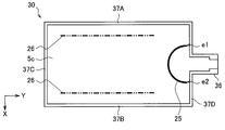
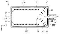
- the irradiation line 25 may have a substantially semicircular arc shape, for example, as shown in FIG.
- the arc-shaped irradiation line 25 has a diameter equal to or larger than the opening width b 0 of the lip portion 36.
- it has a center on a straight line passing through the center of the opening width of the lip portion 36, and becomes a part of a circumference having a diameter at least equal to or larger than the opening width b 0 of the lip portion 36.
- the molten metal flow 60 shown in FIG. , 61, 62 corresponding to the molten metal flow is formed. That is, the raw material 5 dripped in the supply line 26 flows toward the center in the width direction (X direction) of the hearth 30, and the lip portion in the center in the width direction (X direction) of the hearth 30 to which the molten metal flow 62 hits.
- the molten metal flow 60 is directed to 36.
- the irradiation line 25 is set so that the two end portions e1 and e2 are located in the vicinity of the side wall 37D and close the lip portion 36.
- the surface of the molten metal 5c is irradiated with an electron beam with respect to such an irradiation line 25.
- Marangoni convection is generated, and the molten metal flow 60 toward the lip portion 36 is guided in the direction toward the upstream side of the hearth 30 and toward the side walls 37A and 37B.
- LDI can be dissolved while circulating in the molten metal 5c stored in the hearth 30.
- the actual irradiation position where the electron beam is irradiated onto the irradiation line 25 may not be strictly on the irradiation line 25.
- the actual irradiation position where the electron beam is irradiated may be approximately on the target irradiation line 25, and there is no problem as long as the actual electron beam irradiation locus is within the control range from the target irradiation line 25.
- the two ends e1 and e2 of the irradiation line 25 are positioned in the vicinity of the inner surface of the side wall 37 of the hearth 30.
- the end portions e1 and e2 being positioned in the vicinity of the side wall 37 means that the end portions e1 and e2 are positioned in a region where the separation distance x from the inner side surface of the side wall 37 or the inner side surface of the side wall 37 is 5 mm or less. In such a region, the end portions e1 and e2 of the irradiation line 25 are set and the electron beam is irradiated.
- the skull 7 is formed on the inner surface of the side wall 37 of the hearth 30, and the skull 7 has an electron. A beam may be irradiated.
- the arrangement of the electron beam irradiation line 25 is such that “the two end portions e1 and e2 are the side walls 37 (37A, 37B, 37C, In the vicinity of any one of 37D ”and“ so that the irradiation line 25 blocks the lip portion 36 (so that the upstream line S2 and the lip portion 36 are reliably separated by the irradiation line 25) ”.
- the mode shown in FIG. 4 or 7 is merely an example, and even if the irradiation line 25 is far from the side wall 37D as compared with these examples, it is allowed.
- the downstream region S3 between the upstream region S2 and the side wall 37D is It becomes wider than the case shown in FIG.
- the irradiation line 25 can be arranged in the downstream region S3, it can also be arranged in the central portion in the longitudinal direction of the hearth 30 as shown in FIG. At this time, the two ends e1 and e2 of the irradiation line 25 may be positioned on the side walls 37A and 37B.
- the two ends e1 and e2 of the irradiation line 25 are provided with lip portions 36 as shown in FIG. It is preferable to be located on the side wall 37D. Thereby, the scanning distance of the electron beam is shortened, and the time required for scanning the irradiation line 25 once can be shortened. As a result, the temperature of the molten metal 5c in the irradiation line 25 can be increased efficiently, and the molten metal flow 61 that goes upstream from the irradiation line 25 can be formed earlier in the surface layer of the molten metal 5c.
- line irradiation It is preferable to appropriately set the irradiation conditions such as the heat transfer amount of the electron beam, the scanning speed, and the heat flux distribution.
- the heat transfer amount [W] of the electron beam is a parameter that affects the temperature rise of the molten metal 5 c in the irradiation line 25 and the flow rate of Marangoni convection (molten flow 61) caused by the temperature rise.
- the heat transfer amount of the electron beam is small, the molten metal flow 61 that overcomes the main flow of the molten metal 5c cannot be formed. Accordingly, the larger the heat transfer amount of the electron beam, the better. For example, it is 0.15-0.60 [MW].
- the scanning speed [m / s] of the electron beam is a parameter that affects the flow velocity of the molten metal flow 61.
- the irradiation line 25 on the surface of the molten metal 5c is repeatedly scanned with the electron beam emitted from the electron gun 20E. If the scanning speed of the electron beam at this time is slow, a position where the electron beam is not irradiated for a long time on the irradiation line 25 is generated.
- the surface temperature of the molten metal 5c at the position where the electron beam is not irradiated rapidly decreases, and the flow velocity of the molten metal flow 61 generated from the position decreases.
- the scanning speed of the electron beam is preferably as high as possible, and is, for example, 1.0 to 20.0 [m / s].
- the heat flux distribution on the surface of the molten metal 5c by the electron beam is a parameter that affects the amount of heat transferred from the electron beam to the molten metal 5c.
- the heat flux distribution corresponds to the size of the electron beam aperture.
- the steeper heat flux distribution can be given to the molten metal 5c as the aperture of the electron beam is smaller.
- the heat flux distribution on the surface of the molten metal 5c is expressed by, for example, the following formula (1) (see, for example, Non-Patent Document 1).
- the following equation (1) represents that the heat flux is exponentially attenuated according to the distance from the center of the electron beam.
- (x, y) represents the position on the molten metal surface
- (x 0 , y 0 ) represents the electron beam center position
- ⁇ represents the standard deviation of the heat flux distribution
- q 0 represents the heat flux at the electron beam center position. q 0 is set such that when the heat transfer amount of the electron gun is Q, the sum of the heat fluxes q on all the molten metal surfaces in the hearth becomes Q as shown in the above equation (2).
- the irradiation conditions such as the heat transfer amount, scanning speed, and heat flux distribution of the electron beam for line irradiation are limited by the equipment specifications for electron beam irradiation. Therefore, when setting the electron beam irradiation conditions, it is preferable that the amount of heat transfer is as large as possible, the scanning speed is fast, and the heat flux distribution is narrow (the aperture of the electron beam is small) within the range of equipment specifications. .
- the irradiation of the electron beam to the irradiation line 25 may be performed by one electron gun or a plurality of electron guns.
- an electron gun 20E dedicated to line irradiation may be used, or electron guns 20A and 20B for melting raw materials or electrons for warming molten metal. You may combine with the electron gun of other uses, such as gun 20C and 20D (refer to Drawing 3).
- the irradiation line 25 is arranged such that the two ends e1 and e2 are located on the side wall 37 of the hearth 30 and close the lip portion 36 with respect to the surface of the molten metal 5c in the hearth 30. Are irradiated with an electron beam. As a result, Marangoni convection due to the temperature gradient of the surface of the molten metal 5c is generated, and as shown in FIG. 6, a surface layer flow (molten flow 61) of the molten metal 5c upstream from the irradiation line 25 is formed on the surface layer of the molten metal 5c. .
- the molten metal flow 61 can push back the molten metal flow 60 toward the lip portion 36 from the center of the hearth 30 to the upstream side of the irradiation line 25, and impurities such as LDI 8 floating in the molten metal 5 c are transferred from the hearth 30 to the mold 40. Spilling out can be suppressed.
- the molten metal 5 c pushed back into the hearth 30 is melted while circulating through the molten metal 5 c in the hearth 30 or is captured by the skull 7.
- the irradiation line 25 has a convex shape protruding toward the upstream side.
- the molten metal flow 60 toward the lip portion 36 can be directed from the irradiation line 25 to the side walls 37 ⁇ / b> A and 37 ⁇ / b> B of the hearth 30 by the molten metal flow 61.
- the LDI 8 floating on the surface layer of the molten metal 5 c can be fixed to the skull 7 on the inner surface of the side wall of the hearth 30.
- the LDI 8 can be dissolved while circulating in the molten metal 5 c in the hearth 30. Thereby, it is possible to suppress impurities from flowing out from the hearth 30 to the mold 40 and entering the ingot 50.
- the conventional titanium alloy manufacturing method allows the molten metal to stay in the hearth for a long time, thereby fixing the HDI to the skull formed on the bottom surface of the hearth and dissolving the LDI in the molten metal to remove impurities. It was general. For this reason, conventionally, in order to ensure the residence time of the molten metal in the hearth, it has been common to use a long hearth. However, according to the method for manufacturing a metal ingot according to the present embodiment, even when the residence time of the molten metal in the hearth is relatively short, impurities can be removed appropriately, so that it is possible to use a short hearth. Become.
- the method of manufacturing a metal ingot by the electron beam melting method according to the present embodiment is different from the first embodiment in the shape of the electron beam irradiation line 25.
- differences from the metal ingot manufacturing method according to the first embodiment will be mainly described, and the same settings, processing, and the like as those of the metal ingot manufacturing method according to the first embodiment will be described in detail. Is omitted.
- the case where the short hearth electron beam melting furnace 1 shown in FIG. 3 is used will be described.
- the present invention is not limited to this example, and the long hearth electron beam shown in FIG. It can also be applied to melting furnaces.
- the irradiation line 25 is divided between the first straight portion L1 along the side wall 37D and the first straight line between the two end portions e1 and e2.
- a T-shape is formed which includes a second straight line portion L2 extending substantially vertically from the portion L1 toward the upstream.
- the lip portion 36 is closed by the first straight portion L1.
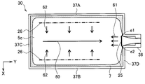
- FIG. 9 is a plan view showing an example of the irradiation line 25 in the method for producing a metal ingot according to the present embodiment, and shows a molten metal flow on the surface of the molten metal 5 c in the hearth 30.
- FIG. 10 is a plan view showing an example of the irradiation line 25 in the method for producing a metal ingot according to the present embodiment.
- the plan view of FIG. 9 corresponds to the hearth 30 of the electron beam melting furnace 1 of FIG. Further, in FIG. 10, the description of the skull formed on the inner surface of the side wall 37 of the hearth 30 is omitted.
- the irradiation line 25 has a T shape, and the irradiation line 25 is irradiated with an electron beam. Also in this case, as in the case of irradiating the irradiation line 25 shown in the first embodiment with the electron beam, a temperature gradient is generated in the heat insulation irradiation region 23 and the region near the irradiation line 25, and Marangoni convection is generated. appear. Due to the occurrence of Marangoni convection, a molten metal stream 61 is generated upstream from the irradiation line 25, and the LDI is pushed back upstream.
- FIG. 9 shows the flow of the molten metal 5 c when the temperature of the raw material 5 dropped onto the supply line 26 is higher than that of the molten metal 5 c already stored in the hearth 30.
- Marangoni convection is a flow from a high temperature region to a low temperature region.
- the raw material 5 dropped on the supply line 26 rides on the molten metal flow 62 and flows toward the center portion in the width direction (X direction) of the hearth 30, and rides on the molten metal flow 63, It flows toward the side walls 37A and 37B.
- a molten metal stream 60 is formed.
- the LDI 8 floating in the molten metal 5 c also flows on the molten metal flow 60 toward the lip portion 36.
- Impurities such as LDI8 are molded from the lip portion 36 by pushing the LDI flowing on the molten metal flow 60 toward the lip portion 36 back to the upstream side of the hearth 30 to form a surface flow of the molten metal 5c away from the lip portion 36. 40 can be prevented from flowing out.
- a T-shaped irradiation line is formed on the surface of the molten metal 5 c. 25 reaches the region irradiated with the electron beam.
- the irradiation line 25 is substantially parallel to the side wall 37D, and includes a first straight portion L1 that closes the lip portion 36, and a second straight portion L2 that extends toward the upstream from the approximate center of the first straight portion L1. Become. Two ends e1 and e2 of the first straight line portion L1 are located on the side wall 37D.
- the molten metal temperature T2 in the region near the irradiation line 25 irradiated with the electron beam is higher than the temperature T0 in the heat retaining irradiation region 23. For this reason, Marangoni convection is generated, and a molten metal flow 61 is formed upstream from the irradiation line 25.
- the molten metal flow 60 toward the lip portion 36 is pushed back upstream by the molten metal flow 61 generated in the irradiation line 25 and reaches the side walls 37 ⁇ / b> A and 37 ⁇ / b> B of the hearth 30. It becomes.
- the LDI that has flowed onto the lip portion 36 on the molten metal flow 60 moves toward the side walls 37A and 37B of the hearth 30 and then adheres to the skull 7 formed on the side wall of the hearth 30 and moves. Disappear.
- the LDI is melted while circulating through the hearth 30 on the surface flow of the molten metal 5c.
- the T-shaped irradiation line 25 is irradiated with an electron beam.
- the molten metal flow which goes to the upstream from the irradiation line 25 arises.
- the LDI in the molten metal 5 c can be prevented from flowing out from the hearth 30 to the mold 40. Therefore, it is possible to suppress impurities from flowing out from the hearth 30 to the mold 40 and entering the ingot 50.
- the electron beam may be irradiated to the irradiation line 25 using three electron guns. That is, as shown in FIG. 10, the irradiation lines d1 and d3 constituting the first straight line portion L1 and the irradiation line d2 constituting the second straight line portion L2 are each irradiated with an electron beam.
- the first linear portion L1 along the side wall 37D substantially parallel to the width direction (X direction) of the hearth 30 is irradiated with an electron beam using two electron guns.
- the irradiation line d1 and the irradiation line d3 share each end and are arranged on substantially the same straight line.
- the irradiation line d1 and the irradiation line d3 overlap in an area having a length of 5 mm or more, and the accuracy of the irradiation position control of the electron beam with respect to the irradiation line 25 is lowered, the irradiation line d1 and It is possible to prevent a gap from occurring with the irradiation line d3.
- the irradiation line length b 2 of the first straight line portion L1 (that is, the sum of the lengths of the irradiation lines d1 and d3 in FIG. 10) is the irradiation line height h 2 of the second straight line portion L2 described later or an electron gun. It is determined in consideration of the heat transfer amount of the electron beam output from.
- the irradiation line length b 2 is set to be at least larger than the opening width of the lip portion 36.
- the irradiation line length b 2 is smaller than the opening width of the lip portion 36, a molten metal flow from the upstream region S 2 of the hearth 30 toward the lip portion 36 is created in the portion where the electron beam is not irradiated, and the LDI is from the hearth 30. There is a possibility of flowing out into the mold 40. For this reason, it is preferable that the irradiation line length b 2 is at least larger than the opening width of the lip portion 36.
- the irradiation line length b 2 only needs to be smaller than the width of the hearth 30, but the longer the irradiation line length b 2 is, the more necessary to scan the first straight line portion L1 shown in FIG. 9 once. The time will be longer.
- the time required to scan the irradiation line 25 once becomes longer the molten metal flow 61 toward the side wall of the hearth 30 is weakened by the electron beam irradiation, and the possibility that the LDI passes through the lip portion 36 is increased.
- the lengths of the irradiation lines d1 and d3 constituting the first straight line portion L1 are preferably substantially the same.
- the number of electron guns that irradiate the first linear portion L1 with an electron beam is not limited to this example, and may be one or three or more.
- the second straight line portion L2 is irradiated with an electron beam by, for example, one electron gun.
- Irradiation line height h 2 of the second straight portion L2 is also determined in consideration of the heat transfer amount of the electron beam output from the irradiation line length b 2, or an electron gun of the first straight portion L1. The larger the irradiation line height h 2, the time required to scan the irradiation line 25 once becomes longer, also decreases the degree of temperature rise of the molten metal 5c of the second straight portion L2.
- the irradiation line height h 2 shortens the time required for scanning as much as possible, and, as can be increased efficiently the temperature of the molten metal 5c, is set.
- the irradiation line height h 2 is desirably about 2/5 or more and 3/5 or less of the irradiation line length b 2 .
- the second straight line portion L2 is preferably set on the center line of the hearth 30 as shown in FIG. Thereby, the flow of the molten metal 5c in the hearth 30 can be made substantially symmetrical with respect to the center line. Further, the direction of the molten metal flow in the electron beam irradiation line 25 can be directed to the side walls 37 ⁇ / b> A and 37 ⁇ / b> B closer to the irradiation line 25. Thereby, the accuracy of fixing impurities such as LDI to the skull 7 can be increased.
- the actual irradiation position where the electron beam is irradiated onto the irradiation line 25 may not be strictly on the irradiation line 25.
- the actual irradiation position where the electron beam is irradiated may be approximately on the target irradiation line 25, and there is no problem as long as the actual electron beam irradiation locus is within the control range from the target irradiation line 25.
- both ends e1 and e2 of the first straight line portion L1 in the electron beam irradiation locus are located in the vicinity of the inner side surface of the side wall of the hearth 30.
- the end portions e1 and e2 being positioned in the vicinity of the side wall 37 means that the end portions e1 and e2 are positioned in a region where the separation distance x from the inner side surface of the side wall 37 or the inner side surface of the side wall 37 is 5 mm or less. In such a region, the end portions e1 and e2 of the irradiation line 25 are set and the electron beam is irradiated.
- the skull 7 is formed on the inner surface of the side wall 37 of the hearth 30, and the skull 7 has an electron. A beam may be irradiated.
- the irradiation conditions such as the heat transfer amount, the scanning speed, and the heat flux distribution of the electron beam are limited by the equipment specifications for irradiating the electron beam. The Therefore, when setting the electron beam irradiation conditions, the heat transfer amount of the electron beam is increased as much as possible, the scanning speed is increased, and the heat flux distribution is narrowed (the electron beam aperture is reduced) within the range of the equipment specifications. It is preferable.
- the irradiation line 25 in the manufacturing method of the metal ingot concerning this embodiment is comprised by the 1st linear part L1 and the 2nd linear part L2.
- the molten metal flow 61 formed by irradiating the T-shaped irradiation line 25 with the electron beam is formed by superimposing the flows formed by the first straight portion L1 and the second straight portion L2.
- the irradiation method of the electron beam along the T-shaped irradiation line 25 is determined based on at least one of the irradiation line length b 2 and the irradiation line height h 2 and the heat transfer amount of the electron gun. Is done. By setting these values, the vector of the surface flow of the molten metal 5c from the irradiation line 25 toward the side wall 37 of the hearth 30 can be determined.
- the direction of the flow can be determined.
- the irradiation method of the irradiation line 25 may be determined only from the relationship between the irradiation line length b 2 and the irradiation line height h 2 .
- the parameters are set so that the scanning distances of the electron guns (that is, the lengths of the irradiation lines d1, d2, and d3) are substantially the same, and the scanning speed and the heat flux distribution are also substantially the same. May be. That is, the irradiation line length b 2, and 2 times the irradiation line height h 2.
- the molten metal flow 60 toward the lip portion 36 is considered in consideration of the irradiation line length b 2 and the irradiation line height h 2 and the heat transfer amount of each electron gun.
- the irradiation method of the irradiation line 25 so that it may be pushed back upstream by the molten metal flow 61 which goes to the side walls 37A and 37B of the hearth 30.
- the flow formed by the first straight portion L1 and the second straight portion L2 is overlapped to form the molten metal flow 61.
- the speed at which the LDI is directed toward the side wall 37 of the hearth 30 can be increased, and the skull 7 is fixed.
- the accuracy can be further increased. Therefore, at least one of the heat transfer amount, the scanning speed, and the heat flux distribution of each electron gun is set based on the setting of the electron gun that irradiates the irradiation line 25 with the electron beam shown in the first embodiment. Even if it is made smaller, it is possible to achieve an effect equal to or greater than that of the first embodiment.
- the flow of the surface of the molten metal 5c toward the lip portion 36 is caused to flow from the irradiation line 25.
- the LDI flowing toward the lip portion 36 can be directed to the side wall 37 of the hearth 30 and fixed to the skull 7 of the side wall 37 of the hearth 30.
- the LDI can be dissolved while circulating in the molten metal 5 c in the hearth 30. Thereby, it can suppress that LDI flows out into the mold 40 from the hearth 30, and mixes in an ingot.
- the irradiation line 25 is not particularly limited, and “the two end portions e1 and e2 are in the vicinity of the side wall 37 (any one of 37A, 37B, 37C, and 37D)” in the downstream region S3. As long as “the irradiation line 25 blocks the lip portion 36 (so that the upstream line S2 and the lip portion 36 are reliably separated by the irradiation line 25)”, any form can be taken. .
- the irradiation line 25 may be disposed in the center portion in the longitudinal direction of the hearth 30 or may be disposed in the vicinity of the lip portion 36. From the viewpoint of more reliably preventing the LDI from flowing out of the hearth 30 into the mold 40, the irradiation line 25 is preferably arranged as close to the lip portion 36 as possible.
- the irradiation line 25 extends substantially vertically from the first straight portion L1 along the side wall 37D between the two ends e1 and e2 and upstream from the first straight portion L1. Let it be a T-shape consisting of the second straight line portion L2. By irradiating such an irradiation line 25 with an electron beam, the molten metal flow toward the lip portion 36 can be pushed back upstream in the irradiation line 25 and directed toward the side wall 37 of the hearth 30.
- the LDI floating on the surface of the molten metal 5 c can be fixed to the skull 7 on the side wall 37 of the hearth 30.
- the LDI can be dissolved while circulating in the molten metal 5 c in the hearth 30. Thereby, it can suppress that LDI flows out into the mold 40 from the hearth 30, and mixes in an ingot.
- the molten metal flow 61 formed by irradiating the irradiation line 25 with the electron beam includes the first straight portion L1 and the second straight portion. Since the flow formed by the irradiation of the electron beam at each position with L2 is formed by being superimposed, the flow becomes strong. Therefore, the LDI can be securely fixed to the skull. It is also possible to weaken the heat transfer amount, scanning speed, or heat flux distribution setting of the electron gun.
- the conventional titanium alloy manufacturing method allows the molten metal to stay in the hearth for a long time, thereby fixing the HDI to the skull formed on the bottom surface of the hearth and dissolving the LDI in the molten metal to remove impurities. It was general. For this reason, conventionally, in order to ensure the residence time of the molten metal in the hearth, it has been common to use a long hearth. However, according to the method for manufacturing a metal ingot according to the present embodiment, even when the residence time of the molten metal in the hearth is relatively short, impurities can be removed appropriately, so that it is possible to use a short hearth. Become.
- the method for manufacturing a metal ingot according to the present embodiment is substantially the same as the method for manufacturing the metal ingot according to the first embodiment, but the shape of the irradiation line 25 is substantially the same, but an electron gun that irradiates an electron beam.
- the number of is different.
- differences from the metal ingot manufacturing method according to the first embodiment will be mainly described, and the same settings, processing, and the like as those of the metal ingot manufacturing method according to the first embodiment will be described in detail. Is omitted.
- the short hearth electron beam melting furnace 1 shown in FIG. 3 is used will be described.
- the present invention is not limited to this example, and the long hearth electron beam shown in FIG. It can also be applied to the melting furnace 1A.
- FIG. 11 is a plan view showing an example of the irradiation line 25 in the method for producing a metal ingot according to the present embodiment.
- the irradiation line 25 is a convex shape that protrudes upstream from the lip portion 36, as in the first embodiment shown in FIG. It is.
- the irradiation line 25 is V-shaped, for example.
- the V-shaped irradiation line 25 shown in FIG. 11 extends from the four corners of the hearth 30 toward the center of the hearth 30 from the corners at both ends of the side wall 37D where the lip portion 36 is provided. It consists of one straight part and a second straight part. The end e1 of the first straight part is located at one end of the side wall 37D, and the end e2 of the second straight part is located at the other end of the side wall 37D.
- the irradiation of the electron beam to the first linear portion and the second linear portion is performed by different electron guns. That is, the electron beam is irradiated onto the V-shaped irradiation line 25 by two electron guns.
- the irradiation range of the electron beam is limited due to restrictions such as equipment space, and the irradiation along the V-shaped irradiation line 25 shown in FIG. 4 is performed by one electron gun as in the first embodiment.
- the electron beam may be irradiated using a plurality of electron guns as in this embodiment.
- the electron beam is irradiated onto the irradiation line 25 using two electron guns so that the irradiation trajectories of the electron beam intersect or overlap each other on the surface of the molten metal 5c.
- the electron beam is irradiated so that these linear portions intersect at a portion where the first linear portion and the second linear portion are connected (V-shaped apex portion). May be. That is, the first straight portion and the second straight portion are not connected at the end opposite to the ends e1 and e2 of the side wall 37D, but the first straight portion and the second straight portion. And are connected so as to intersect.
- the accuracy of the electron beam irradiation position control decreases due to evaporation of volatile valuable elements such as aluminum.
- the melting of the raw material by the electron beam irradiation in the EB furnace is performed in the vacuum chamber.
- the volatile valuable element evaporates, the degree of vacuum in the vacuum chamber decreases, and the straightness of the electron beam decreases.
- it becomes difficult for the two electron guns to accurately perform irradiation along the V-shaped irradiation line 25 in which two linear portions as shown in FIG. 4 are connected at their respective ends. If a gap is generated between the two straight portions, a flow of the surface of the molten metal 5c from the gap toward the lip portion 36 is formed, and the possibility that the LDI flows out to the lip portion 36 is increased.
- the irradiation line 25 is arranged so that the two end portions e1 and e2 are positioned on the side wall 37 and the lip portion 36 is closed. Furthermore, in order to reliably prevent the LDI in the molten metal 5c in the hearth 30 from flowing out from the lip portion 36, the irradiation trajectories of the electron beams output from the two electron guns are crossed. Thereby, even if the accuracy of the electron beam irradiation position control is somewhat lowered, the first straight portion and the second straight portion intersect each other, so that no gap is generated between these straight portions.
- the LDI in the molten metal 5 c in the hearth 30 does not flow out from the lip portion 36.
- the length from the intersection to the end of both the first straight line portion and the second straight line portion is 5 mm or more, the possibility of LDI flowing out to the lip portion 36 can be further reduced.
- the first straight line portion and the second straight line portion only need to be connected at other than the respective end portions.
- the half of the half width D of the hearth 30 is separated from the corner opposite to the corner of the hearth 30 in the width direction of the hearth 30.
- the lengths of the first straight line portion and the second straight line portion are the lengths from the corners of the hearth 30 to the intersections.
- a V-shaped irradiation line 25 in which two straight portions as shown in FIG. 4 are connected at their respective ends may be arranged.
- a curved irradiation line 25 such as a parabola may be arranged as a convex shape having a vertex on the center line of the hearth 30. Or you may arrange
- the irradiation line arranged on the surface of the molten metal in the hearth is formed into a linear shape substantially parallel to the width direction of the hearth.
- the molten metal flow path to the lip portion through which the molten metal in the hearth flows out to the mold is closed.
- LDI which is an impurity floating on the surface of the molten metal is pushed back into the hearth so as not to flow out from the lip portion to the mold.
- the LDI pushed back into the hearth dissolves while staying in the hearth. As a result, it is possible to prevent LDI from flowing into the mold.
- FIG. 12 is a plan view showing an irradiation line 25 in the method for producing a metal ingot according to the present embodiment.
- FIG. 13 is an explanatory diagram showing a molten metal flow formed on the surface of the molten metal 5c when the irradiation line 25 shown in FIG. 12 is irradiated with an electron beam.
- the plan view of FIG. 12 corresponds to the hearth 30 of the electron beam melting furnace 1 of FIG.
- the present invention is not limited to this example, and the long hearth electron beam melting furnace shown in FIG. The present invention can also be applied to the furnace 1A.
- the two ends e1 and e2 are located in the vicinity of the side wall 37 of the hearth 30 and are close to the surface of the molten metal 5c in the hearth 30 so as to close the lip portion 36.
- the irradiation line 25 is set. Specifically, as shown in FIG. 12, the irradiation line 25 has a linear shape substantially parallel to the width direction of the hearth 30 between the two ends e1 and e2.
- the two ends e1 and e2 of the irradiation line 25 are located in the vicinity of the side wall 37D where the lip portion 36 is provided.
- the irradiation line 25 shown in FIG. 12 has a length substantially the same as the opening width of the lip portion 36.
- the irradiation line 25 is disposed in the downstream region S3 between the upstream region S2 including the supply line 26 and the side wall 37D.
- the electron beam is irradiated onto the surface of the molten metal 5c with respect to such an irradiation line 25.
- Marangoni convection due to the temperature gradient of the surface of the molten metal 5c is generated, and as shown in FIG. 13, a surface layer flow (molten flow 61) of the molten metal 5c from the irradiation line 25 toward the upstream side is formed on the surface layer of the molten metal 5c.
- the temperature of the molten metal dropped on the supply line 26 (raw material supply temperature T ⁇ b> 1) is already stored in the hearth 30.
- the region near the supply line 26 where the melted raw material 5 (molten metal) is dropped becomes a high-temperature region having a higher temperature than the molten metal 5c in the other regions. Therefore, as shown in FIG. 13, the molten metal 5c in the region near the supply line 26 flows from the supply line 26 to the center in the width direction (X direction) of the hearth 30, and a molten metal flow 62 is formed on the surface layer of the molten metal 5c. Is done.
- the molten metal 5 c in the region near the supply line 26 extends from the supply line 26 to the side walls 37 ⁇ / b> A and 37 ⁇ / b> B in the width direction (X direction) of the hearth 30. Also flows, and a molten metal flow (a molten metal flow 63 in FIG. 5) is formed on the surface layer of the molten metal 5c.
- the LDI 8 contained in the molten metal dropped on the supply line 26 rides on the molten metal flow (the molten metal flow 63 in FIG. 5) and flows toward the side walls 37A and 37B of the hearth 30 and on the inner side surfaces of the side walls 37A and 37B. It adheres to and is captured by the skull 7 formed.
- a molten metal stream 60 is formed.
- the LDI 8 floating in the molten metal 5 c also flows on the molten metal flow 60 toward the lip portion 36.
- the LDI flowing on the molten metal flow 60 toward the lip portion 36 is pushed back to the upstream side of the hearth 30 and away from the lip portion 36. It is preferable to form a surface layer flow of the molten metal 5c.
- the two end portions e1 and e2 are positioned in the vicinity of the side wall 37D, and the lip portion 36 is closed.
- a shaped irradiation line 25 is disposed on the surface of the molten metal 5c.
- the molten metal temperature in the region near the irradiation line 25 is higher than that in the heat retaining irradiation region 23. For this reason, Marangoni convection is generated, and a molten metal flow 61 is formed upstream from the irradiation line 25.
- the molten metal flow 61 is a flow that pushes back the LDI 8 that has flowed to the lip portion 36 on the molten metal flow 60 in the center in the width direction of the hearth 30 back to the upstream side of the hearth 30.
- the LDI 8 that has flowed toward the lip portion 36 by the molten metal flow 61 is pushed back upstream in the irradiation line 25 and flows into the hearth 30.
- the LDI 8 pushed back into the hearth 30 is melted while circulating through the hearth 30 on the surface flow of the molten metal 5c.
- the LDI 8 moves toward the side walls 37 ⁇ / b> A and 37 ⁇ / b> B of the hearth 30 and then adheres to the skull 7 formed on the side wall 37 of the hearth 30 and does not move.
- the two end portions e1 and e2 are located in the vicinity of the side wall 37 and the irradiation line 25 is disposed so as to close the lip portion 36. Then, the electron beam is irradiated. As a result, a molten metal flow 61 is formed in the vicinity of the irradiation line 25 from the high temperature region of the molten metal 5 c to the upstream side, and impurities such as LDI flowing to the lip portion 36 side are pushed back upstream of the irradiation line 25. Therefore, the impurities can be prevented from flowing out from the hearth 30 into the mold 40. As a result, it can suppress that an impurity mixes in an ingot.
- a linear irradiation line 25 is arranged.
- the scanning distance of the electron beam can be shortened.
- the irradiation line 25 is desirably arranged along the side wall 37D.
- the side wall 37 ⁇ / b> D is substantially parallel to the width direction (X direction) of the hearth 30.
- the molten metal flow 62 from each of the supply lines 26 toward the center of the hearth 30 collides with the central portion of the hearth 30 in the width direction, and flows toward the lip portion 36 along the longitudinal direction (Y direction) of the hearth 30. 60 is formed.
- the molten metal flow 60 is substantially parallel to the longitudinal direction of the hearth 30.
- the irradiation line 25 along the side wall 37D of the hearth 30, the flow of the molten metal 5c (the molten metal flow 60) toward the lip portion 36 can be efficiently dammed. Further, a molten metal flow 61 is formed from the irradiation line 25 toward the upstream. As a result, the LDI 8 that has flowed toward the lip portion 36 along with the flow of the molten metal 5 c can be pushed back away from the lip portion 36 by the molten metal flow 61 and can be retained in the hearth 30.
- the irradiation line 25 may be disposed in the downstream region S3 between the upstream region S1 including at least the supply line 26 and the side wall 37D.
- the irradiation line 25 is preferably disposed at the inlet to the lip portion 36.
- the length of the irradiation line 25 is at least the opening width of the lip portion 36.
- the length of the irradiation line 25 is substantially the same as the opening width of the lip portion 36.
- the LDI 8 is surely pushed back to the inner side of the hearth 30 before flowing into the lip portion 36, and therefore does not flow out of the hearth 30.
- the arrangement of the irradiation line 25 in the method for producing a metal ingot according to the present embodiment can be applied not only to the short hearth shown in FIGS. 12 and 13 but also to the long hearth.
- 14 and 15 show an example in which a linear irradiation line 25 is arranged in a long hearth (hereinafter, referred to as “long hearth 31, 33”) including a melting hearth 31 and a refining hearth 33.
- the melting hearth 31 and the refining hearth 33 are modeled as one hearth.
- FIG. 14 similarly to FIGS.
- a linear irradiation line 25 having a length substantially the same as the opening width of the lip portion 36 is disposed at the inlet to the lip portion 36.
- the irradiation line 25 is disposed so that the two end portions e1 and e2 are located on the side wall 37D and close the lip portion 36.
- LDI8 which flows toward the lip
- the LDI 8 stays in the long hearths 31 and 33 and can reliably prevent the long hearths 31 and 33 from flowing into the mold 40.
- the irradiation line 25 may be disposed in the downstream region S3 between the upstream region S2 including the raw material supply region 28 where the raw material 5 is dropped and the side wall 37D.
- the raw material supply region 28 to which the raw material 5 is dripped is usually at the most upstream position in the longitudinal direction (Y direction negative side) of the long hearths 31 and 33. is there. That is, the raw material supply region 28 is in the vicinity of the side wall 37 ⁇ / b> C opposite to the lip portion 36 in the longitudinal direction of the long hearts 31 and 33. Therefore, for example, as shown in FIG.
- the irradiation line 25 may be arranged at the center in the longitudinal direction of the long hearts 31 and 33.
- the longitudinal center positions of the long hearts 31 and 33 are located in the downstream area S3 on the downstream side of the upstream area S2 including the raw material supply area 28.
- the two ends e1 and e2 of the irradiation line 25 are positioned in the vicinity of the side walls 37A and 37B. Thereby, it is possible to suppress the LDI 8 from passing through the irradiation line 25 and flowing out to the lip portion 36.
- the actual irradiation position where the electron beam is irradiated onto the irradiation line 25 may not be strictly on the irradiation line 25.
- the actual irradiation position where the electron beam is irradiated may be approximately on the target irradiation line 25, and there is no problem as long as the actual electron beam irradiation locus is within the control range from the target irradiation line 25.
- the end portions e1 and e2 are positioned in the vicinity of the side wall 37 means that the end portions e1 and e2 are positioned in a region where the distance x from the inner side surface of the side wall 37 or the inner side surface of the side wall 37 is 5 mm or less. .
- the ends e1 and e2 of the irradiation line 25 are set and the electron beam is irradiated, but there is no problem even if the skull 7 is formed on the inner surface of the side wall 37 of the long hearths 31 and 33. 7 may be irradiated with an electron beam.
- the irradiation conditions such as the heat transfer amount, the scanning speed, and the heat flux distribution of the electron beam are limited by the equipment specifications for irradiating the electron beam. The Therefore, when setting the electron beam irradiation conditions, the heat transfer amount of the electron beam is increased as much as possible, the scanning speed is increased, and the heat flux distribution is narrowed (the electron beam aperture is reduced) within the range of the equipment specifications. It is preferable.
- the lip portion 36 is closed by the irradiation line 25, so that the LDI 8 is dammed in the hearth 30 and dissolved while the LDI 8 is circulating in the hearth.
- the LDI 8 is prevented from flowing out from the hearth 30 to the mold 40.
- dissolves LDI8 may flow out into the mold 40 from the hearth 30.
- FIG. Therefore, in order to reduce the possibility that the LDI 8 flows out from the hearth 30 to the mold 40, the dissolution of the LDI 8 existing in the hearth 30 is promoted.
- the surface of the molten metal 5c in the hearth 30 may be irradiated with an electron beam for promoting LDI melting (corresponding to the “second electron beam” of the present invention).
- the electron beam for promoting LDI dissolution may be applied to a stagnation position where stagnation is caused by the flow of the molten metal 5c, for example.
- the LDI 8 tends to stay at the stagnation position of the flow of the molten metal 5c.
- the electron beam for promoting LDI dissolution does not need to be continuously irradiated, and may be appropriately irradiated to the stagnation position of the flow of the molten metal 5c where the LDI 8 stays.
- the electron gun for irradiating the electron beam for promoting LDI dissolution may use an electron gun (not shown) for promoting LDI dissolution, or may be used for electron guns 20A and 20B for melting raw materials or for keeping molten metal.
- the other electron guns such as the electron guns 20C and 20D (see FIG. 3) may also be used.
- the stagnation position of the flow of the molten metal 5c may be specified by simulation in advance. As described above, the stagnation position can be specified by performing a simulation based on the set position and shape of the irradiation line 25, the heat transfer amount of the electron beam, the scanning speed, and the like.
- the irradiation line 25 may have a convex shape that protrudes from the upstream of the hearth 30 toward the downstream lip portion 36.
- the irradiation line 25 has a V-shape in which two end portions e1 and e2 are located in the vicinity of the side walls 37A and 37B and project toward the lip portion 36. May be. Thereby, since the lip
- the LDI 8 can be pushed back to the inside of the hearth 30.
- the irradiation line 25 may have an arc shape in which two end portions e1 and e2 are located in the vicinity of the side walls 37A and 37B and project toward the lip portion 36. Also in this case, since the lip portion 36 is blocked, it is possible to suppress the LDI 8 in the molten metal 5 c from flowing out to the lip portion 36. In addition, by irradiating the irradiation line 25 with an electron beam, a flow of the molten metal 5c from the irradiation line 25 to the upstream can be formed. As a result, the LDI 8 can be pushed back to the inside of the hearth 30.
- the irradiation line 25 may have a U shape that is convex from the upstream of the hearth 30 toward the lip portion 36.
- the U-shaped irradiation line 25 includes a first straight line portion L1, a second straight line portion L2, and a third straight line portion L3.
- the first straight line portion L1 is disposed substantially in parallel along the side wall 37D between the two end portions e1 and e2.
- the first straight line portion L1 is disposed so as to close the lip portion 36.
- the second straight line portion L2 and the third straight line portion L3 are disposed so as to extend substantially vertically from the both ends of the first straight line portion L1 along the pair of side walls 37A and 37B facing each other toward the upstream. Has been.
- Both ends e1 and e2 of the irradiation line 25 are located in the vicinity of the side walls 37A and 37B of the hearth 30. Thereby, since the lip
- FIG. by irradiating the irradiation line 25 with an electron beam, a flow of the molten metal 5c from the irradiation line 25 to the upstream can be formed. As a result, the LDI 8 can be pushed back to the inside of the hearth 30.
- the U-shaped irradiation line 25 has an angle at which the first straight line portion L1 and the second straight line portion L2 are connected, and an angle at which the first straight line portion L1 and the third straight line portion L3 are connected. However, it may be a right angle as shown in FIG. 18 and may be rounded.
- the actual irradiation position where the electron beam is irradiated onto the irradiation line 25 may not be strictly on the irradiation line 25.
- the actual irradiation position where the electron beam is irradiated may be approximately on the target irradiation line 25, and there is no problem as long as the actual electron beam irradiation locus is within the control range from the target irradiation line 25.
- the end portions e1 and e2 are positioned in the vicinity of the side wall 37 means that the end portions e1 and e2 are positioned in a region where the distance x from the inner side surface of the side wall 37 or the inner side surface of the side wall 37 is 5 mm or less. .
- the end portions e1 and e2 of the irradiation line 25 are set and the electron beam is irradiated.
- the skull 7 is formed on the inner surface of the side wall 37 of the hearth 30, and the skull 7 has an electron.
- a beam may be irradiated.
- the irradiation line 25 may be irradiated with an electron beam using one electron gun, and the irradiation line 25 may be irradiated with electrons using a plurality of electron guns. A beam may be irradiated.
- the irradiation line 25 when the irradiation line 25 as shown in FIGS. 16 to 18 is arranged, when the irradiation line 25 is irradiated with an electron beam, the irradiation line 25 is directed upstream from the irradiation line 25 and the width direction (X The flow of the molten metal 5c toward the center of the direction is formed. That is, on the upstream side of the irradiation line 25, a flow of the molten metal 5c from the side walls 37A and 37B toward the center is formed. At this time, the molten metal temperature in the region near the irradiation line 25 is higher than the molten metal temperature in the heat retaining irradiation region 23. Therefore, Marangoni convection is generated, and a molten metal flow 61 is formed from the side walls 37A and 37B of the hearth 30 toward the center.
- the stagnation position of the flow of the molten metal 5c may be irradiated with an electron beam for promoting LDI melting.
- the LDI 8 tends to stay at the stagnation position of the molten metal flow.
- the manufacturing method of the metal ingot which concerns on this embodiment was demonstrated.
- the irradiation line 25 is arranged such that the two ends e1 and e2 are positioned on the side wall 37 and the lip portion 36 is closed with respect to the surface of the molten metal 5c in the hearth 30.
- the molten metal flow path to the lip part 36 which flows out the molten metal in the hearth 30 to the mold is closed.
- the LDI 8 is dammed up at the inlet to the lip portion 36.
- the LDI 8 continues to circulate in the hearth 30 and is dissolved during that time. Thereby, LDI8 contained in the molten metal 5c can be prevented from flowing out from the lip portion 36 to the mold 40.
- the scanning distance of the electron beam can be shortened by making the irradiation line 25 linear. Therefore, even if the scanning speed of the electron beam is reduced, the weakening of the flow of the molten metal 5c formed by irradiating the irradiation line 25 with the electron beam is small. Therefore, the LDI 8 is surely pushed back to the inner side of the hearth 30 before flowing into the lip portion 36, and therefore does not flow out of the hearth 30.
- the irradiation line 25 has a linear shape, the electron gun that irradiates the electron beam only needs to be moved linearly, so that the control is easy and the number of electron guns to be used is minimized. Can do.
- the conventional titanium alloy manufacturing method allows the molten metal to stay in the hearth for a long time, thereby fixing the HDI to the skull formed on the bottom surface of the hearth and dissolving the LDI in the molten metal to remove impurities. It was general. For this reason, conventionally, in order to ensure the residence time of the molten metal in the hearth, it has been common to use a long hearth. However, according to the method for manufacturing a metal ingot according to the present embodiment, even when the residence time of the molten metal in the hearth is relatively short, impurities can be removed appropriately, so that it is possible to use a short hearth. Become.
- the hearth to which the method for producing a metal ingot according to the present invention is applied may be a multi-stage hearth continuously arranged by combining a plurality of divided hearts.
- the two-stage hearth 30 may be configured by combining the first hearth 30A and the second hearth 30B and continuously arranging them.
- the first hearth 30A (corresponding to “divided hearth” of the present invention) stores the molten material 5c of the raw material 5 dropped along the supply line 26, for example, similarly to the hearth 30 shown in FIG. This is a device for refining and removing impurities in the molten metal 5c.
- the first hearth 30A is a rectangular hearth, and includes four side walls 37A, 37B, 37C, and 37D.
- a lip portion 36 is provided on the side wall 37D of the first hearth 30A.
- the molten metal 5c of the first hearth 30A that has flowed out of the lip portion 36 is stored in the second hearth 30B.
- the second hearth 30B (corresponding to the “divided hearth” of the present invention) is for refining while removing the molten metal 5c flowing from the first hearth 30A and removing impurities in the molten metal 5c.
- the second hearth 30B is also a rectangular hearth, and includes four side walls 37A, 37B, 37C, and 37D.
- a lip portion 36 is provided on the side wall 37D of the second hearth 30B.
- the molten metal 5 c of the second hearth 30 B that has flowed out of the lip portion 36 flows out into the mold 40.
- the two ends e1 and e2 are located on the side wall 37, and the lip portion 36
- the irradiation line 25 is arranged so as to close the area.
- the surface of the molten metal 5 c is irradiated to the irradiation line 25, thereby generating a molten metal stream 61 upstream from the irradiation line 25.
- the multiple-stage hearth shown in FIG. 19 is a two-stage hearth, but the present invention is not limited to this example.
- the multiple-stage hearth may be a three-stage or higher hearth continuously arranged by combining three or more divided hearths.
- the irradiation line is arranged so that the two end portions are located in the vicinity of the side wall and the lip portion is closed.
- the V-shaped irradiation line 25 is disposed so that the two end portions e1 and e2 are positioned on the side wall 37D and the lip portion 36 is covered.
- the arc-shaped irradiation line 25 is disposed so that the two end portions e1 and e2 are located on the side wall 37D and the lip portion 36 is covered.
- an electron beam was irradiated.
- the T-shaped irradiation line 25 is disposed so that the two end portions e1 and e2 are positioned on the side wall 37D and the lip portion 36 is covered.
- Examples 4 and 5 are examples in which an electron beam is irradiated onto the irradiation line 25 using two electron guns.
- Example 4 as shown in FIG. 11, two end portions e1 and e2 are positioned at both ends of the side wall 37D, and the V-shaped irradiation line 25 is disposed so as to cover the lip portion 36, and irradiation is performed.
- the line 25 was irradiated with an electron beam.
- Example 5 as shown in FIG. 25, the irradiation line 25 was arranged similarly to FIG. 11 (Example 4), while the scanning direction of the electron beam was changed.
- the electron beam heat transfer amounts of the two electron guns used in Example 4 and Example 5 were both 0.125 [MW].
- Example 6 as shown in FIG. 27, the two end portions e1 and e2 are positioned at both ends of the side wall 37D, and the V-shaped irradiation line 25 is disposed so as to cover the lip portion 36, and irradiation is performed.
- the line 25 was irradiated with an electron beam.
- two end portions e1 and e2 are positioned at both ends of the side wall 37D, and the V-shaped irradiation line 25 is disposed so as to cover the lip portion 36, and irradiation is performed.
- the line 25 was irradiated with an electron beam.
- the V-shaped apex Q was shifted from the center in the width direction of the hearth 30.
- the linear irradiation line 25 is disposed so that the two end portions e1 and e2 are located on the side wall 37D and the lip portion 36 is covered. On the other hand, an electron beam was irradiated.
- the two end portions e1 and e2 are positioned at both ends of the side wall 37D, and the linear irradiation line covers the lip portion 36. 25 was arranged, and the irradiation line 25 was irradiated with an electron beam.
- the two end portions e1 and e2 are positioned at both ends of the side wall 37D, and the long hearths 31 and 33 are straight in the longitudinal center.
- An irradiation line 25 having a shape was arranged, and the irradiation line 25 was irradiated with an electron beam.
- the two end portions e1 and e2 are located on the side walls 37A and 37B, and the V-shape projecting toward the lip portion 36 so as to cover the lip portion 36.
- An irradiation line 25 was arranged, and the irradiation line 25 was irradiated with an electron beam.
- the two end portions e1 and e2 are located on the side walls 37A and 37B, and the arc-shaped irradiation protrudes toward the lip portion 36 so as to cover the lip portion 36.
- the line 25 was arranged, and the irradiation line 25 was irradiated with an electron beam.
- the two end portions e1 and e2 are located on the side walls 37A and 37B, and the U-shape projecting toward the lip portion 36 so as to cover the lip portion 36.
- An irradiation line 25 was arranged, and the irradiation line 25 was irradiated with an electron beam.
- Comparative Example 2 a simulation of the method of Patent Document 1 was performed. That is, as shown in FIG. 38, a zigzag irradiation line 25 is arranged on the surface of the molten metal 5c in the long hearts 31 and 33, and the irradiation line 25 is irradiated with an electron beam.
- Comparative Example 3 As compared with Example 4, as shown in FIG. 40, the electron beam was irradiated without intersecting the apex of the V-shaped irradiation line 25. Note that the electron beam heat transfer amounts of the two electron guns used in Comparative Example 3 were both 0.125 MW.
- the electron beam was irradiated without intersecting the three straight lines of the T-shaped irradiation line 25 as shown in FIG.
- the irradiation line 25 shown in FIG. 42 includes a first straight line portion L1 and a second straight line portion L2 along the side wall 37D provided with the lip portion 36, and a third straight line portion L3 perpendicular to the side wall 37D. Consists of. The first straight line portion L1, the second straight line portion L2, and the third straight line portion L3 are not in contact with each other.
- the heat transfer amount of the electron beam irradiated along the first straight line portion L1 and the second straight line portion L2 is 0.05 MW
- the heat transfer amount of the electron beam irradiated along the third straight line portion L3 is It was set to 0.15 MW.
- the scanning speed of the electron beam irradiated along the first straight line portion L1 and the second straight line portion L2 is 2.9 m / s
- the scanning of the electron beam irradiated along the third straight line portion L3 is performed. The speed was 3.6 m / s. *
- Table 1 shows the simulation conditions of this example.
- LDI is titanium nitride
- the simulation was performed assuming that the particle size of titanium nitride is 3.5 mm and the density of titanium nitride is 10% smaller than that of the molten metal 5c.
- Examples 1 to 13 and Comparative Examples 1 to 4 are shown below.
- 20 to 24, 26, 28, and 30 to 36 show the simulation results of Examples 1 to 13, respectively
- FIGS. 37, 39, 41, and 43 show the simulation results of Comparative Examples 1 to 4, respectively.
- the irradiation position of the electron beam for line irradiation irradiated to the irradiation line 25 is a representative position.
- the temperature distribution of the surface of the molten metal 5c in the hearth and the behavior of LDI flowing on the surface of the molten metal 5c are shown.
- a circled region having a high temperature is an irradiation line at that time.
- the upper and lower two belt-like high temperature portions show the two supply lines 26, and the low temperature portion near the inner surface of the hearth shows the portion where the skull 7 is formed.
- Example 1 In the first embodiment, as shown in FIG. 20, a high temperature region is formed along the irradiation line 25 that closes the lip portion 36, and a molten metal flow 61 is formed upstream from the irradiation line 25. For this reason, as shown in FIG. 20, all the LDI that has flowed from the supply line toward the lip portion 36 flows on the molten metal flow 61 toward the side walls 37A and 37B, and passes through the lip portion 36 to the mold 40 side. There is no streamline extending to From this, it can be seen that the LDI in the hearth 30 is pushed back upstream and does not flow out from the lip portion 36 to the mold 40. FIG.
- FIG. 21 shows arrows indicating the flow direction and strength of the molten metal 5c at each point in the vicinity of the irradiation line 25 of the first embodiment. Also from FIG. 21, it can be seen that a strong flow of molten metal 5c having a high flow velocity is formed upstream from the irradiation line 25 and toward the side walls 37A and 37B.
- Example 2 As shown in FIG. 22, also in the second embodiment, as in the first embodiment, a high temperature region is formed along the irradiation line 25 that closes the lip portion 36, and a molten metal flow 61 is formed upstream from the irradiation line 25. . For this reason, all of the LDI that has flowed from the supply line toward the lip portion 36 flows on the molten metal flow 61 toward the side walls 37A and 37B, and there is no streamline extending to the mold 40 side through the lip portion 36. From this, it can be seen that the LDI in the hearth 30 is pushed back upstream and does not flow out from the lip portion 36 to the mold 40.
- Example 3 Also in the third embodiment, as in the first and second embodiments, as shown in FIG. 23, a high temperature region is formed along the irradiation line 25 that closes the lip portion 36, and a molten metal stream 61 is formed upstream from the irradiation line 25. ing. For this reason, all of the LDI that has flowed from the supply line toward the lip portion 36 flows on the molten metal flow 61 toward the side walls 37A and 37B, and there is no streamline extending to the mold 40 side through the lip portion 36. From this, it can be seen that the LDI in the hearth 30 is pushed back upstream and does not flow out from the lip portion 36 to the mold 40.
- Example 4 the electron beam was irradiated to the irradiation line 25 using two electron guns.
- the electron beam was irradiated to the irradiation line 25 so that the electron beams of the two electron guns were positioned at the apex of the V shape at the same timing.
- Example 5 when the electron beam of one electron gun is positioned at the apex of the V shape, the irradiation beam 25 is positioned so that the electron beam of the other electron gun is positioned at the center of the irradiation line. Irradiated with an electron beam.
- FIG. 24 shows the simulation result of the fourth embodiment
- FIG. 26 shows the simulation result of the fifth embodiment.
- a high temperature region is formed along the irradiation line 25 that closes the lip portion 36, and upstream from the irradiation line 25.
- a molten metal flow 61 is formed. For this reason, all of the LDI that has flowed from the supply line toward the lip portion 36 flows on the molten metal flow 61 toward the side walls 37A and 37B, and there is no streamline extending to the mold 40 side through the lip portion 36. From this, it can be seen that the LDI in the hearth 30 is pushed back upstream and does not flow out from the lip portion 36 to the mold 40.
- Examples 6 and 7 are the cases where the V-shaped irradiation line 25 is arranged as in Example 1, but the V-shaped shape is different from Example 1. However, in Examples 6 and 7, as in Examples 1 to 5, as shown in FIGS. 28 and 30, a high-temperature region is formed along the irradiation line 25 that closes the lip portion 36, and upstream from the irradiation line 25. A molten metal flow 61 is formed. For this reason, all of the LDI that has flowed from the supply line toward the lip portion 36 flows on the molten metal flow 61 toward the side walls 37A and 37B, and there is no streamline extending to the mold 40 side through the lip portion 36. From this, it can be seen that the LDI in the hearth 30 is pushed back upstream and does not flow out from the lip portion 36 to the mold 40.
- Example 8 to 10 In Examples 8 to 10, a linear irradiation line 25 was disposed.
- FIG. 31 shows the simulation result of Example 8
- FIG. 32 shows the simulation result of Example 9
- FIG. 33 shows the simulation result of Example 10.
- the arrangement of the linear irradiation lines 25 or the hearth used is different.
- a high-temperature region is formed along the irradiation line 25 that closes the lip portion 36, and upstream from the irradiation line 25.
- a molten metal flow 61 is formed.
- the LDI stays in the same position and then circulates in the hearth again.
- LDI dissolves while circulating in the hearth.
- the stagnation position may be irradiated with an electron beam for promoting LDI dissolution to promote LDI dissolution.
- Example 11 to 13 In Examples 11 to 13, the convex irradiation line 25 protruding from the upstream toward the lip portion 36 is disposed.
- FIG. 34 shows the simulation result of Example 11
- FIG. 35 shows the simulation result of Example 12
- FIG. 36 shows the simulation result of Example 13.
- the convex shape of the irradiation line 25 is different.
- a high-temperature region is formed along the irradiation line 25 that closes the lip portion 36, and upstream from the irradiation line 25.
- a molten metal flow 61 is formed.
- the electron beam was irradiated so that the irradiation line 25 closed the lip portion 36.
- the heat transfer amount, the scanning speed, and the heat flux distribution of the electron beam are appropriately set, the ends e1 and e2 of the irradiation line 25 are positioned on the side wall 37 of the hearth 30, and the upstream region S2 including the supply line 26 and the lip If it irradiates so that the flow path between the parts 36 may be blocked, arrangement of irradiation line 25 can be changed suitably. Also in this case, it is clear that LDI shows the same behavior as that shown in Examples 1 to 13 above.
- Comparative Example 1 In Comparative Example 1, the irradiation line 25 is not irradiated with an electron beam. Therefore, as shown in FIG. 37, the LDI flows freely from the high temperature region of the supply line 26 toward the center portion of the hearth 30 and rides on the molten metal flow 60 in the center portion of the hearth 30 to cause a large amount of LDI to lip. It flowed out through the part 36 into the mold.
- Comparative Example 2 is a simulation result of the method described in Patent Document 1. That is, as shown in FIG. 38, the electron beam was scanned zigzag on the surface of the molten metal 5c in the hearths 31 and 33 in the direction opposite to the flowing direction of the molten metal to the mold. As shown in FIG. 38, the irradiation line 25 has a zigzag shape along the longitudinal direction of the hearths 31 and 33.
- the raw material 5 is supplied from the raw material supply area 28 on the upstream side in the longitudinal direction of the hearth (that is, the side opposite to the lip portion).
- the melting hearth 31 and the refining hearth 33 are modeled as one hearth.
- Comparative Example 2 As shown in FIG. 39, LDI gradually gathered in the lip portion 36 and flowed out into the mold 40 as it went from the raw material supply region 28 to the lip portion 36.
- the simulation was performed for the case where the long hearth was used.
- the LDI passes through the irradiation line 25, and the LDI easily flows out toward the mold even in the case of the short hearth. I can guess.
- Comparative Example 3 (Comparative Example 3)
- the first straight line portion and the second straight line portion do not intersect with each other, and therefore there is a portion where the electron beam is not irradiated in the vicinity of the center line of the hearth 30.
- the LDI flowed out toward the mold 40 through the lip portion 36 through the portion not irradiated with the electron beam.
- Comparative Example 4 In Comparative Example 4, as shown in FIG. 42, since the first straight line portion L1, the second straight line portion L2, and the third straight line portion L3 do not intersect, the vicinity of the inlet to the lip portion 36 of the hearth 30 There are places where the electron beam is not irradiated. For this reason, as shown in FIG. 43, the LDI flowed out toward the mold 40 through the lip portion 36 through the portion where the electron beam was not irradiated.
- Example regarding behavior of molten metal flow the behavior of the molten metal flow is verified for the V-shaped irradiation line 25 according to the first embodiment and the irradiation line 25 according to the second embodiment. did.
- Example 1 (V-shaped irradiation line 25) of the above example and Example 3 (T-shaped irradiation line 25) were compared.
- unsteady calculations were performed because the flow and temperature of the molten metal change from moment to moment as the electron beam scans.
- the electron guns of Examples 1 and 3 were set as shown in Table 2 below.
- Example 3 three electron guns are used, and the T-shaped irradiation line 25 has a ratio (h 2 / b 2 ) between the irradiation line length (b 2 ) and the irradiation line height (h 2 ). ) To be 2/5.
- the total flow ratio is a ratio of values represented by the product of the average flow velocity of the molten metal flow and the length of the line segment AB.
- the speed of the molten metal flow from the vicinity of the lip portion 36 toward the side wall 37A is higher in both the first and third embodiments.
- the flow velocity is higher than in Example 1.
- the maximum flow rate was 0.13 m / s in Example 3, while 0.11 m / s in Example 1.
- the total flow rate ratio of the molten metal flow passing through the line segment AB parallel to the hearth side wall 37 shown in the flow velocity distribution on the molten metal surface in FIG. 44 is larger in the third embodiment than in the first embodiment. It was.
- the embodiment 3 in which the surface flow of the melt toward one side wall is formed by the generation of a single Marangoni convection is more rapid in the embodiment 3 in which the formation of two Marangoni convections is performed. It was found that a surface flow was formed.
- Example of Electron Beam for Promoting LDI Dissolution a simulation was performed for Example 8 using an electron beam for promoting LDI dissolution. Also in this simulation, since the flow and temperature of the molten metal 5c change every moment by the scanning of the electron beam, unsteady calculation was performed.
- LDI was titanium nitride, and the simulation was performed on the assumption that the particle size of titanium nitride is 5 mm and the density of titanium nitride is 10% smaller than that of the molten metal 5c.
- two end portions e1 and e2 are positioned on a side wall 37D provided with a lip portion 36, and The linear irradiation line 25 is disposed so as to close the lip portion 36.
- the heat transfer amount of the electron beam for preventing LDI outflow was 0.25 MW
- the scanning speed was 1.6 m / s
- the standard deviation of the heat flux distribution was 0.02 m.
- the electron beam was irradiated to the stagnation position of the molten metal flow using two electron guns for promoting LDI dissolution in the hearth 30 different from the electron gun for preventing LDI outflow.
- the irradiation time of the electron beam by the electron gun for preventing LDI outflow was set to 1 second, and the irradiation position of the electron beam was fixed at the stagnation position of the molten metal flow.
- the heat transfer amount of the electron beam for promoting LDI dissolution was 0.25 MW, and the standard deviation of the heat flux distribution was 0.02 m.
- FIG. 45 shows the simulation results.
- FIG. 45 shows a temperature distribution diagram on the surface of the molten metal in the hearth 30 and the behavior of LDI at four times after the LDI stays in the molten metal 5c.
- a region with a high temperature in the vicinity of the lip portion 36 indicates the irradiation position of the electron beam with respect to the irradiation line 25 at that time
- the lip portion 36 of the supply line 26 A region with a high temperature in the vicinity of the end portion indicates the irradiation position of the electron beam for promoting LDI dissolution at that time.
- the two upper and lower belt-like high temperature portions indicate the two supply lines 26, and the low temperature portion near the inner surface of the hearth indicates the portion where the skull 7 is formed.
- the right side in FIG. 45 shows the position of the LDI at each time.
- the LDI in the vicinity of the supply line 26 moves within the hearth 30 with the passage of time 0.8 seconds after the LDI stays in the molten metal. 27.7 seconds after the LDI stayed in the molten metal, a plurality of LDIs stayed at the positions indicated by the circles in the LDI behavior (stagnation position of the molten metal flow).
- an electron beam was irradiated with two electron guns for promoting LDI dissolution for 1 second after 27.8 seconds after the LDI stayed in the molten metal.
- 28.8 seconds after LDI stayed in the molten metal LDI dissolved.
- the metal raw material 5 to be melted by the method for producing a metal ingot according to the present embodiment is, for example, a raw material of titanium or a titanium alloy, and a titanium ingot 50 (ingot) using the hearth 30 and the mold 40 is used.
- the example which manufactures was mainly demonstrated.
- the method for producing a metal ingot of the present invention is also applicable to the case of producing an ingot of a metal raw material by melting various metal raw materials other than the titanium raw material.
- a high melting point active metal capable of producing an ingot using an electron beam melting furnace provided with an electron gun capable of controlling the irradiation position of an electron beam and a hearth for storing a molten metal raw material
- the present invention can be applied to the production of ingots of metal raw materials such as tantalum, niobium, vanadium, molybdenum or zirconium in addition to titanium. That is, the present invention can be applied particularly effectively when manufacturing an ingot containing 50% by mass or more of each of the elements listed here.
- the shape of the hearth to which the method for producing a metal ingot according to the present embodiment is applied is not limited to a rectangular shape.
- the method for producing a metal ingot according to this embodiment can be applied to a hearth other than a rectangular shape in which the side wall of the hearth has a curved shape such as an ellipse or an ellipse.
- Electron beam melting furnace (EB furnace) 5 Metal raw material 5c Molten metal 7 Skull 8 LDI 10A, 10B Raw material supply part 20A, 20B Electron gun for melting raw material 20C, 20D Electron gun for molten metal insulation 20E Electron gun for line irradiation 23 Thermal insulation irradiation area 25 Irradiation line 26 Supply line 30 Refining hearth 36 Lip part 37A, 37B 37C Side wall where no lip portion is provided 37D First side wall 40 Mold 50 Ingot 61, 62, 63 Molten metal flow
Landscapes
- Engineering & Computer Science (AREA)
- Mechanical Engineering (AREA)
- Chemical & Material Sciences (AREA)
- General Engineering & Computer Science (AREA)
- Materials Engineering (AREA)
- Metallurgy (AREA)
- Organic Chemistry (AREA)
- Manufacturing & Machinery (AREA)
- Physics & Mathematics (AREA)
- Plasma & Fusion (AREA)
- Geology (AREA)
- General Life Sciences & Earth Sciences (AREA)
- Environmental & Geological Engineering (AREA)
- Thermal Sciences (AREA)
- Crystallography & Structural Chemistry (AREA)
- Life Sciences & Earth Sciences (AREA)
- Health & Medical Sciences (AREA)
- Toxicology (AREA)
- Manufacture And Refinement Of Metals (AREA)
- Continuous Casting (AREA)
- Furnace Details (AREA)
Priority Applications (6)
| Application Number | Priority Date | Filing Date | Title |
|---|---|---|---|
| EA201992437A EA039285B1 (ru) | 2017-04-13 | 2018-04-13 | Способ производства металлического слитка |
| JP2019512583A JP6922977B2 (ja) | 2017-04-13 | 2018-04-13 | 金属鋳塊の製造方法 |
| UAA201911104A UA125661C2 (uk) | 2017-04-13 | 2018-04-13 | Спосіб виробництва металевого зливка |
| EP18784257.0A EP3611278B1 (de) | 2017-04-13 | 2018-04-13 | Verfahren zur herstellung von metallbarren |
| US16/604,906 US11833582B2 (en) | 2017-04-13 | 2018-04-13 | Method for producing metal ingot |
| CN201880039148.2A CN110770359B (zh) | 2017-04-13 | 2018-04-13 | 金属铸块的制造方法 |
Applications Claiming Priority (8)
| Application Number | Priority Date | Filing Date | Title |
|---|---|---|---|
| JP2017079733 | 2017-04-13 | ||
| JP2017-079735 | 2017-04-13 | ||
| JP2017079732 | 2017-04-13 | ||
| JP2017-079733 | 2017-04-13 | ||
| JP2017079734 | 2017-04-13 | ||
| JP2017079735 | 2017-04-13 | ||
| JP2017-079734 | 2017-04-13 | ||
| JP2017-079732 | 2017-04-13 |
Publications (1)
| Publication Number | Publication Date |
|---|---|
| WO2018190424A1 true WO2018190424A1 (ja) | 2018-10-18 |
Family
ID=63793277
Family Applications (2)
| Application Number | Title | Priority Date | Filing Date |
|---|---|---|---|
| PCT/JP2018/015555 Ceased WO2018190424A1 (ja) | 2017-04-13 | 2018-04-13 | 金属鋳塊の製造方法 |
| PCT/JP2018/015536 Ceased WO2018190419A1 (ja) | 2017-04-13 | 2018-04-13 | 金属鋳塊の製造方法 |
Family Applications After (1)
| Application Number | Title | Priority Date | Filing Date |
|---|---|---|---|
| PCT/JP2018/015536 Ceased WO2018190419A1 (ja) | 2017-04-13 | 2018-04-13 | 金属鋳塊の製造方法 |
Country Status (6)
| Country | Link |
|---|---|
| US (2) | US11833582B2 (de) |
| EP (2) | EP3611278B1 (de) |
| JP (2) | JP7010930B2 (de) |
| CN (2) | CN110770359B (de) |
| UA (2) | UA125661C2 (de) |
| WO (2) | WO2018190424A1 (de) |
Cited By (1)
| Publication number | Priority date | Publication date | Assignee | Title |
|---|---|---|---|---|
| CN109465419A (zh) * | 2018-12-29 | 2019-03-15 | 陕西天成航空材料有限公司 | 一种电子束离心铸造大尺寸钛合金管设备及方法 |
Families Citing this family (9)
| Publication number | Priority date | Publication date | Assignee | Title |
|---|---|---|---|---|
| US10795037B2 (en) | 2017-07-11 | 2020-10-06 | Reflexion Medical, Inc. | Methods for pet detector afterglow management |
| WO2019099551A1 (en) | 2017-11-14 | 2019-05-23 | Reflexion Medical, Inc. | Systems and methods for patient monitoring for radiotherapy |
| JP7261615B2 (ja) * | 2019-03-01 | 2023-04-20 | 東邦チタニウム株式会社 | ハース、電子ビーム溶解炉、及び鋳造品の製造方法 |
| JP7545257B2 (ja) * | 2020-08-06 | 2024-09-04 | 東邦チタニウム株式会社 | ハース |
| CN111945022B (zh) * | 2020-08-10 | 2021-12-31 | 昆明理工大学 | 一种减少eb炉熔炼钛及钛合金扁锭拉锭时间的方法 |
| RU2753847C1 (ru) * | 2020-10-12 | 2021-08-24 | Публичное акционерное общество "Электромеханика" | Способ и устройство для производства металлического слитка |
| CN112496278A (zh) * | 2020-10-28 | 2021-03-16 | 攀枝花云钛实业有限公司 | 电子束冷床熔炼圆锭的方法 |
| CN114505471B (zh) * | 2022-02-22 | 2024-04-23 | 襄阳金耐特机械股份有限公司 | 一种多自由度浇铸机 |
| CN116555576A (zh) * | 2023-05-23 | 2023-08-08 | 陕西天成航空材料有限公司 | 一种提高钛合金熔炼质量的方法 |
Citations (4)
| Publication number | Priority date | Publication date | Assignee | Title |
|---|---|---|---|---|
| JP2004232066A (ja) | 2003-01-31 | 2004-08-19 | Toho Titanium Co Ltd | 金属チタンの電子ビーム溶解方法 |
| JP2004276039A (ja) * | 2003-03-13 | 2004-10-07 | Toho Titanium Co Ltd | 高融点金属の電子ビーム溶解方法 |
| WO2008078402A1 (ja) * | 2006-12-25 | 2008-07-03 | Toho Titanium Co., Ltd. | 金属インゴットの溶製方法 |
| JP2013001975A (ja) * | 2011-06-18 | 2013-01-07 | Toho Titanium Co Ltd | 金属製造用溶解原料およびこれを用いた金属の溶解方法 |
Family Cites Families (7)
| Publication number | Priority date | Publication date | Assignee | Title |
|---|---|---|---|---|
| US4932635A (en) * | 1988-07-11 | 1990-06-12 | Axel Johnson Metals, Inc. | Cold hearth refining apparatus |
| US4838340A (en) * | 1988-10-13 | 1989-06-13 | Axel Johnson Metals, Inc. | Continuous casting of fine grain ingots |
| JPH04124229A (ja) | 1990-09-14 | 1992-04-24 | Nippon Steel Corp | チタン合金の電子ビーム溶解方法 |
| JP4443430B2 (ja) * | 2005-01-25 | 2010-03-31 | 東邦チタニウム株式会社 | 電子ビーム溶解装置 |
| WO2008084702A1 (ja) | 2007-01-10 | 2008-07-17 | Nikon Corporation | 光学素子、ファインダー光学系、測光光学系及び撮影光学系と、これらを用いた結像方法および測光方法 |
| JP5380264B2 (ja) * | 2009-12-15 | 2014-01-08 | 東邦チタニウム株式会社 | 金属インゴットの溶製方法 |
| JP5580366B2 (ja) | 2012-05-29 | 2014-08-27 | 東邦チタニウム株式会社 | チタンインゴットの製造方法 |
-
2018
- 2018-04-13 UA UAA201911104A patent/UA125661C2/uk unknown
- 2018-04-13 US US16/604,906 patent/US11833582B2/en active Active
- 2018-04-13 CN CN201880039148.2A patent/CN110770359B/zh active Active
- 2018-04-13 UA UAA201911107A patent/UA125662C2/uk unknown
- 2018-04-13 WO PCT/JP2018/015555 patent/WO2018190424A1/ja not_active Ceased
- 2018-04-13 EP EP18784257.0A patent/EP3611278B1/de active Active
- 2018-04-13 WO PCT/JP2018/015536 patent/WO2018190419A1/ja not_active Ceased
- 2018-04-13 JP JP2019512578A patent/JP7010930B2/ja active Active
- 2018-04-13 JP JP2019512583A patent/JP6922977B2/ja active Active
- 2018-04-13 US US16/604,916 patent/US11498118B2/en active Active
- 2018-04-13 CN CN201880040085.2A patent/CN110770360B/zh active Active
- 2018-04-13 EP EP18783838.8A patent/EP3611277B1/de active Active
Patent Citations (4)
| Publication number | Priority date | Publication date | Assignee | Title |
|---|---|---|---|---|
| JP2004232066A (ja) | 2003-01-31 | 2004-08-19 | Toho Titanium Co Ltd | 金属チタンの電子ビーム溶解方法 |
| JP2004276039A (ja) * | 2003-03-13 | 2004-10-07 | Toho Titanium Co Ltd | 高融点金属の電子ビーム溶解方法 |
| WO2008078402A1 (ja) * | 2006-12-25 | 2008-07-03 | Toho Titanium Co., Ltd. | 金属インゴットの溶製方法 |
| JP2013001975A (ja) * | 2011-06-18 | 2013-01-07 | Toho Titanium Co Ltd | 金属製造用溶解原料およびこれを用いた金属の溶解方法 |
Non-Patent Citations (2)
| Title |
|---|
| See also references of EP3611278A4 |
| TAO MENG, FACTORS INFLUENCING THE FLUID FLOW AND HEAT TRANSFER IN ELECTRON BEAM MELTING OF TI-6A1-4V, 2009 |
Cited By (2)
| Publication number | Priority date | Publication date | Assignee | Title |
|---|---|---|---|---|
| CN109465419A (zh) * | 2018-12-29 | 2019-03-15 | 陕西天成航空材料有限公司 | 一种电子束离心铸造大尺寸钛合金管设备及方法 |
| CN109465419B (zh) * | 2018-12-29 | 2021-03-30 | 陕西天成航空材料有限公司 | 一种电子束离心铸造大尺寸钛合金管设备及方法 |
Also Published As
| Publication number | Publication date |
|---|---|
| UA125662C2 (uk) | 2022-05-11 |
| JP6922977B2 (ja) | 2021-08-18 |
| US20200164432A1 (en) | 2020-05-28 |
| JP7010930B2 (ja) | 2022-01-26 |
| JPWO2018190424A1 (ja) | 2020-02-27 |
| US11833582B2 (en) | 2023-12-05 |
| US20200122226A1 (en) | 2020-04-23 |
| EP3611277A1 (de) | 2020-02-19 |
| EP3611278B1 (de) | 2023-02-08 |
| EP3611277B1 (de) | 2022-03-16 |
| CN110770359A (zh) | 2020-02-07 |
| EP3611277A4 (de) | 2020-08-05 |
| UA125661C2 (uk) | 2022-05-11 |
| CN110770359B (zh) | 2021-10-15 |
| EP3611278A1 (de) | 2020-02-19 |
| CN110770360A (zh) | 2020-02-07 |
| JPWO2018190419A1 (ja) | 2020-05-14 |
| EP3611278A4 (de) | 2020-08-05 |
| US11498118B2 (en) | 2022-11-15 |
| CN110770360B (zh) | 2022-02-01 |
| WO2018190419A1 (ja) | 2018-10-18 |
Similar Documents
| Publication | Publication Date | Title |
|---|---|---|
| WO2018190424A1 (ja) | 金属鋳塊の製造方法 | |
| US10549385B2 (en) | Method for laser melting with at least one working laser beam | |
| KR102077416B1 (ko) | 금속 재료들을 주조하기 위한 시스템들 및 방법들 | |
| US9539640B2 (en) | Hearth and casting system | |
| JP2012176427A (ja) | 金属溶製用溶解炉およびこれを用いた金属の溶製方法 | |
| RU2623524C2 (ru) | Способ непрерывного литья сляба из титана или титанового сплава | |
| JP6279963B2 (ja) | チタンまたはチタン合金からなるスラブの連続鋳造装置 | |
| JP5896811B2 (ja) | チタンまたはチタン合金からなる鋳塊の連続鋳造用の鋳型およびこれを備えた連続鋳造装置 | |
| JP3759933B2 (ja) | 高融点金属の電子ビーム溶解方法 | |
| US10022784B2 (en) | Continuous casting method for ingots obtained from titanium or titanium alloy | |
| JPH10102112A (ja) | 高炉出銑樋 | |
| JP7095470B2 (ja) | チタン鋳塊またはチタン合金鋳塊の製造方法および製造装置 | |
| JP2010163290A (ja) | ガラス溶融炉 | |
| EP3225329A1 (de) | Verfahren zum stranggiessen einer bramme mit titan oder einer titanlegierung | |
| EA039286B1 (ru) | Способ производства металлического слитка | |
| JP2001272172A (ja) | 障壁を含む複数炉床装置 |
Legal Events
| Date | Code | Title | Description |
|---|---|---|---|
| 121 | Ep: the epo has been informed by wipo that ep was designated in this application |
Ref document number: 18784257 Country of ref document: EP Kind code of ref document: A1 |
|
| ENP | Entry into the national phase |
Ref document number: 2019512583 Country of ref document: JP Kind code of ref document: A |
|
| NENP | Non-entry into the national phase |
Ref country code: DE |
|
| ENP | Entry into the national phase |
Ref document number: 2018784257 Country of ref document: EP Effective date: 20191113 |