WO2018193579A1 - Dispositif de reconnaissance d'image - Google Patents
Dispositif de reconnaissance d'image Download PDFInfo
- Publication number
- WO2018193579A1 WO2018193579A1 PCT/JP2017/015889 JP2017015889W WO2018193579A1 WO 2018193579 A1 WO2018193579 A1 WO 2018193579A1 JP 2017015889 W JP2017015889 W JP 2017015889W WO 2018193579 A1 WO2018193579 A1 WO 2018193579A1
- Authority
- WO
- WIPO (PCT)
- Prior art keywords
- behavior detection
- detection space
- behavior
- distance
- image recognition
- Prior art date
- Legal status (The legal status is an assumption and is not a legal conclusion. Google has not performed a legal analysis and makes no representation as to the accuracy of the status listed.)
- Ceased
Links
Images




Classifications
-
- G—PHYSICS
- G06—COMPUTING OR CALCULATING; COUNTING
- G06F—ELECTRIC DIGITAL DATA PROCESSING
- G06F3/00—Input arrangements for transferring data to be processed into a form capable of being handled by the computer; Output arrangements for transferring data from processing unit to output unit, e.g. interface arrangements
- G06F3/01—Input arrangements or combined input and output arrangements for interaction between user and computer
-
- G—PHYSICS
- G06—COMPUTING OR CALCULATING; COUNTING
- G06T—IMAGE DATA PROCESSING OR GENERATION, IN GENERAL
- G06T7/00—Image analysis
- G06T7/20—Analysis of motion
-
- G—PHYSICS
- G06—COMPUTING OR CALCULATING; COUNTING
- G06T—IMAGE DATA PROCESSING OR GENERATION, IN GENERAL
- G06T7/00—Image analysis
- G06T7/50—Depth or shape recovery
- G06T7/521—Depth or shape recovery from laser ranging, e.g. using interferometry; from the projection of structured light
Definitions
- the present invention relates to an image recognition apparatus for recognizing human behavior based on a signal input from a distance image sensor capable of three-dimensional recognition of an imaging target.
- Patent Document 1 An operation input device is known in which a device mounted on a vehicle operates accordingly.
- a TOF (Time Of Flight) distance image sensor (hereinafter referred to as a TOF camera) capable of three-dimensional recognition of an object to be photographed is commercially available.
- a TOF camera capable of three-dimensional recognition of an imaging target. Since the TOF camera can detect the time until the light from the light source hits the measurement target and returns for each pixel, it can capture a stereoscopic image including position information corresponding to the distance in the depth direction.
- the behavior of the driver is detected only in a specific two-dimensional or three-dimensional space (hereinafter referred to as behavior detection space) determined in advance, and the operation of the in-vehicle device is performed. It is assumed to be reflected. For example, if the driver's hand is in the vicinity of the steering wheel (handle) as in a normal driving state, and control is performed so that the in-vehicle device is operated according to the behavior of the driver's hand or finger, In a situation where the driver moves his / her hand unconsciously, the in-vehicle device will not operate.
- behavior detection space a specific two-dimensional or three-dimensional space
- the operation input device as in Patent Document 1 monitors only the behavior of the driver's hands and fingers, it is difficult to increase the types of operation patterns that can be recognized, and it is also difficult to increase the recognition accuracy. For example, when trying to distinguish the differences in the shape of the driver's delicate hands and fingers, the device may incorrectly recognize the shape of the hand or finger, and the gesture operation pattern intended by the driver and the device There is a possibility that a malfunction may occur due to a difference from the operation pattern that is actually recognized.
- an error may occur in the distance measured by the TOF camera.
- the angle of irradiation from the light source varies with temperature and the error increases. Therefore, when the TOF camera is installed in a vehicle room where the temperature changes rapidly, there is a concern about the influence of the distance measured by the TOF camera and the error of the three-dimensional coordinates.
- the behavior detection space is enlarged, reduced, or displaced.
- the in-vehicle device may operate in response to the behavior of the hand performed unconsciously. That is, an operation unintended by the driver is performed without permission. Since such a malfunction is an operation that is not expected by the driver, the driver's thinking may be confused and the driving may be hindered.
- the present invention has been made in view of the above-described circumstances, and an object thereof is to increase the types of recognizable gesture operation patterns and improve operation detection accuracy while suppressing an increase in apparatus cost.
- An object of the present invention is to provide an image recognition apparatus capable of performing the above.
- an image recognition apparatus is characterized by the following (1) to (5).
- the image recognition device having the configuration (1) it is possible to increase the types of gesture operation patterns that can be recognized and to improve operation detection accuracy while suppressing an increase in device cost. That is, the types of operation patterns can be increased by recognizing human behavior in each of the first behavior detection space and the second behavior detection space.
- the first behavior detection space and the second behavior detection space are arranged on the same line as viewed from the distance image sensor, both behaviors can be obtained without increasing the angle of view when the distance image sensor captures an image.
- the detection space can be monitored simultaneously. Therefore, the number of pixels of the image data corresponding to each recognized recognition object increases, and the recognition accuracy is improved.
- the first behavior detection space is assigned to an area where human facial expressions can be recognized
- the second behavior detection space is assigned to an area where human hand or finger movement can be recognized.
- the image recognition device having the configuration (2) above, it is possible to detect the behavior related to the facial expression of the human face by processing the image in the first behavior detection space, and simultaneously process the image in the second behavior detection space. By doing so, it is possible to detect a behavior related to the movement of a human hand or finger.
- the combination of the behavior in the first behavior detection space and the behavior in the second behavior detection space is used, and therefore the types of operations corresponding to these overall behaviors. Can be recognized with higher accuracy.
- the probability that the driver will perform a plurality of special behaviors other than a specific gesture at the same time is very low, so it is easy to distinguish whether a gesture is a specific gesture without recognizing subtle changes in each behavior detection space. it can.
- a first measurement distance to a predetermined specific photographing target recognized based on a signal input from the distance image sensor and a distance from the distance image sensor to the specific photographing target are determined in advance.
- a ratio with a reference distance obtained by actual measurement is calculated and recognized based on a parameter specifying the first behavior detection space and the second behavior detection space, or a signal input from the distance image sensor.
- a measurement value correction unit that corrects the second measurement distance to an arbitrary point of the behavior monitoring target by a correction amount based on the ratio;
- the image recognition device having the configuration (4), even when a large error is included in the result of the distance measured by the distance image sensor, for example, when a TOF camera is used, the error Can be automatically corrected, so that it is possible to prevent malfunctions caused by behaviors detected in regions other than the first behavior detection space and the second behavior detection space.
- At least one of the first behavior detection space and the second behavior detection space is a region adjacent to the fixed portion, or a region around the fixed portion, with a specific fixed portion in the vehicle interior as a reference Assigned to the The image recognition apparatus according to (1) or (2) above.
- the first behavior detection space and the second behavior detection space are determined with reference to a specific fixed part in the passenger compartment.
- the driver's gesture can be recognized only under a specific condition such as the case of the posture. Therefore, it is possible to prevent the device from misrecognizing a behavior that the driver has unconsciously performed as a specific gesture.
- the image recognition apparatus of the present invention it is possible to increase the types of recognizable gesture operation patterns and improve operation detection accuracy while suppressing an increase in apparatus cost. That is, the types of operation patterns can be increased by recognizing human behavior in each of the first behavior detection space and the second behavior detection space.
- the first behavior detection space and the second behavior detection space are arranged on the same line as viewed from the distance image sensor, both behaviors can be obtained without increasing the angle of view when the distance image sensor captures an image.
- the detection space can be monitored simultaneously. Therefore, the number of pixels of the image data corresponding to each recognized recognition object increases, and the recognition accuracy is improved.
- FIG. 1 is a side view showing an example of the positional relationship of each part when the interior of a vehicle equipped with an image recognition device according to an embodiment of the present invention is viewed from the right side of the vehicle.
- FIG. 2 is a block diagram illustrating a configuration example of an in-vehicle system including the image recognition device according to the embodiment of the present invention.
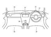
- FIG. 3 is a front view showing a configuration example of the interior of a vehicle in which the image recognition device according to the embodiment of the present invention is mounted.
- FIG. 4 is a flowchart showing an operation example of the image recognition apparatus according to the embodiment of the present invention.
- 5A and 5B are front views showing specific examples of gestures based on the behavior of the driver's hand.
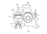
- FIG. 6 is a front view illustrating a configuration example of the interior of a vehicle in which the image recognition device according to the modification is mounted.
- FIG. 3 shows an example of the arrangement of main components in the vicinity of the driver's seat in the vehicle interior.
- the image recognition apparatus of the present invention is used in a state where it is mounted on a vehicle as shown in FIG. 3, for example.
- a driver seat 34 and a passenger seat 35 are provided in the vehicle interior, and a steering wheel 31 is disposed in front of the driver seat 34.
- a display unit 32 having a rectangular display screen is installed near the center of the front dashboard 33.
- the display unit 32 can be used as a display unit of a car navigation device or a car audio device.
- the main body of a head-up display (HUD) is stored below the dashboard 33.
- a transparent combiner (reflecting plate) that reflects display light rises from the inside of the dashboard 33 and appears on the dashboard 33, and is positioned at a position where the driver can visually recognize it.
- a movable control lever 36 is arranged at a position where the driver on the left front side of the driver seat 34 can operate.
- the operation lever 36 is used to switch the transmission mode of the vehicle transmission.
- the TOF camera 21 is fixed on the dashboard 33 slightly ahead of the steering wheel 31.
- the TOF camera 21 is a TOF (Time Of Flight) distance image sensor capable of three-dimensional recognition of an imaging target. That is, the TOF camera 21 can detect the time until the light from the light source hits the measurement target and returns for each pixel, and can capture a stereoscopic image including position information corresponding to the distance in the depth direction.
- TOF Time Of Flight
- FIG. 1 shows an example of the positional relationship of each part when the interior of a vehicle equipped with the image recognition device of the embodiment of the present invention is viewed from the right side of the vehicle.
- the TOF camera 21 shown in FIG. 3 is installed at a position facing the steering wheel 31, and can capture a range in which both the entire steering wheel 31 and the driver's hand operating the steering wheel 31 are reflected simultaneously. As described above, the shooting direction and the angle of view are adjusted in advance.
- the fixed range on the vehicle such as the face 30 f of the driver 30, the hand 30 h, and the steering wheel 31 is included in the shooting range 25 ⁇ / b> A of the TOF camera 21. It is positioned so that
- two behavior detection spaces ArF and ArH are determined in advance as a three-dimensional behavior detection space for detecting a driver's gesture.
- the behavior detection space ArF is a space for recognizing the behavior of the face 30f of the driver 30, and is assigned to an area including the position of the face 30f when the driver 30 is in a normal driving posture as shown in FIG. It has been.
- the behavior detection space ArH is a space for recognizing the behavior of the hand 30h of the driver 30 and is assigned to an area including the position of the hand 30h when the driver 30 is in a normal driving posture as shown in FIG. It has been.
- Each of the behavior detection spaces ArF and ArH is a rectangular parallelepiped three-dimensional space having a fixed size.
- the behavior detection spaces ArF and ArH are automatically adjusted according to the adjusted actual driving posture and position.
- the behavior detection space ArF for detecting the face 30f is assigned to a region separated by a predetermined distance with reference to this position after calculating the actual position of the headrest 34h of the driver seat 34.
- the behavior detection space ArH for detecting the hand 30h is allocated to a region separated by a predetermined distance with reference to this position after calculating the actual posture (tilt angle, etc.) and position of the steering wheel 31. .
- two behavior detection spaces ArH and ArF are assigned to positions shifted from each other in the depth direction (Z direction) along the axis Az in the same shooting direction of the TOF camera 21.
- Z direction depth direction
- a hand and a face in each space can be photographed simultaneously.
- gestures that can be used by recognizing the behavior for each of the plurality of behavior detection spaces ArH and ArF.
- FIG. 2 A configuration example of an in-vehicle system including the image recognition device 10 according to the embodiment of the present invention is shown in FIG.
- the in-vehicle system shown in FIG. 2 is mounted on the vehicle shown in FIGS.
- the image recognition apparatus 10 shown in FIG. 2 can automatically recognize an operation instruction for the in-vehicle device from a predetermined gesture of the driver, that is, a gesture or a gesture, and can control the corresponding in-vehicle device.
- the driver's hand, finger, face and steering wheel 31 are photographed by the TOF camera 21, and the behavior of the hand, finger, face and the like is recognized as a gesture from the three-dimensional image obtained by this photographing. Therefore, the driver can operate the in-vehicle device by a gesture without operating a special button or the like. Therefore, when the driver operates the in-vehicle device, it is not necessary to search for a target button or to release the hand from the steering wheel 31 for the operation, and a function useful for improving safe driving can be provided.
- the image recognition device 10 detects the behavior of hands, fingers, faces, etc. only when they exist inside the predetermined behavior detection spaces ArH, ArF, etc. .
- the driver for example, it is possible to prevent the driver from unintentionally recognizing the movement of the hand moved unconsciously as a specific gesture, and to prevent the in-vehicle device from performing an unexpected operation.
- the TOF camera 21 includes a light source unit 21a and a light receiving unit 21b.
- the light source unit 21a can irradiate the object to be imaged with pulsed light.
- the light receiving unit 21b includes a two-dimensional image sensor formed of a CMOS or the like. Further, for each pixel constituting the two-dimensional image detected by the light receiving unit 21b, distance information corresponding to the time (Time Of Flight) until the light from the light source unit 21a hits a shooting target such as a hand and returns to the light receiving unit 21b is obtained.
- a circuit for detection is built in the TOF camera 21. Therefore, the TOF camera 21 can capture a three-dimensional image.
- the image recognition device 10 includes an image recognition processing unit 11 and a gesture monitoring control unit 12.
- the image recognition processing unit 11 executes information processing on the image information output from the TOF camera 21 at high speed, recognizes a pattern of a specific shape registered in advance, and positions and dimensions of the recognized pattern on the three-dimensional coordinates. It has the function to measure color, movement, shape change and so on.
- the gesture monitoring control unit 12 identifies whether or not the driver's hand exists inside a predetermined behavior detection space. Further, when the driver's hand is present inside the predetermined behavior detection space, the driver's hand, finger, face, etc. are monitored based on the recognition result of the image recognition processing unit 11, and the driver's hand is detected in advance. It is identified whether or not it matches with the gesture pattern registered in. When the gesture monitoring control unit 12 detects a behavior that matches a specific gesture, the gesture monitoring control unit 12 performs a predetermined control.
- the host ECU (electronic control unit) 22 sends information indicating the position and posture of the steering wheel 31, information indicating the position and posture of the driver's seat 34, information indicating ignition on / off of the vehicle, and the like to the gesture monitoring control unit 12. Can be given.
- the HUD unit 23, the car navigation device 24, and the car audio device 26 are connected to the output of the image recognition device 10.
- the image recognition device 10 can control each of the HUD unit 23, the car navigation device 24, and the car audio device 26 based on a driver's gesture.
- a transparent combiner included in the HUD unit 23 rises from below the dashboard 33 shown in FIG. 3 and appears on the dashboard 33.
- the driver can see the vehicle.
- the display light projected from the HUD unit 23 is reflected by the combiner, and a virtual image visible at the position of the driver's eyes is formed.
- the combiner is lowered and stored below the dashboard 33.
- buttons for operating the car navigation device 24 and functions similar to various buttons for operating the car audio device 26 can be assigned to various gestures that can be recognized by the image recognition device 10. It is.
- the driver 30 when performing a gesture operation for activating the operation of the HUD unit 23, the driver 30 keeps the left hand LH and the right hand RH touching the steering wheel 31 as shown in FIG. Move the left hand LH to trace from the bottom to the top. Further, the positions of the left hand LH and the right hand RH at this time are adjusted so as to be located within the region of the behavior detection space ArH.
- This operation is recognized as a specific gesture by the image recognition device 10 based on the image captured by the TOF camera 21, and the image recognition device 10 sends a control signal for activation to the HUD unit 23.
- the driver 30 when performing a gesture operation to end the operation of the HUD unit 23, the driver 30 keeps the left hand LH and the right hand RH touching the steering wheel 31 as shown in FIG. Move to trace the left hand LH from top to bottom. Further, the positions of the left hand LH and the right hand RH at this time are adjusted so as to be located within the region of the behavior detection space ArH.
- This operation is recognized as a specific gesture by the image recognition device 10 based on the image captured by the TOF camera 21, and the image recognition device 10 sends a control signal for ending the operation to the HUD unit 23.
- a more complicated operation than that in FIGS. 5A and 5B may be performed.
- a gesture pattern that expresses a special hand shape by bending or stretching a specific finger or repeating a tracing operation a plurality of times may be employed.
- a gesture that combines the behavior of the hand and the behavior of the face may be employed.
- the HUD unit 23 is activated only when the behavior of the hand as shown in FIG. 5A is detected and the direction of the line of sight of the eyes is facing forward in the face 30f in the behavior detection space ArF. Recognize as a gesture to do.
- the operation of the HUD unit 23 is performed only when the behavior of the hand as shown in FIG. 5B is detected and the direction of the line of sight of the eyes faces the front in the face 30f in the behavior detection space ArF. Is recognized as a gesture for ending.
- the behavior in the behavior detection space ArF and the behavior in the behavior detection space ArH may be assigned to independent device control.
- the hand behavior in the behavior detection space ArH as shown in FIGS. 5A and 5B is assigned as a gesture for operating the HUD unit 23, and the facial behavior in the behavior detection space ArF is the car. It is conceivable to assign it as a gesture for operating a device such as the navigation device 24, the car audio device 26, or an air conditioner.
- the image recognition device 10 may detect a gesture in response to the behavior of the hand or face. That is, since the image recognition apparatus 10 erroneously detects a gesture in a situation where the driver does not intend to perform a gesture, an in-vehicle device such as the HUD unit 23 performs an operation that is not expected by the driver. In order to prevent such a malfunction, the image recognition apparatus 10 has a function of automatically correcting the position of the recognition target recognized based on the three-dimensional image, as will be described later.
- FIG. 4 shows a main operation example of the image recognition apparatus 10 in the embodiment of the present invention. That is, the computer (not shown) or the image recognition processing unit 11 built in the gesture monitoring control unit 12 of the image recognition apparatus 10 shown in FIG. 2 responds to the driver's gesture according to the procedure shown in FIG. Implement the control.
- the procedure shown in FIG. 1 includes a process for correcting the position of the hand to be recognized that is recognized based on the three-dimensional image output from the TOF camera 21. Specifically, a correction ratio R1 is obtained with reference to the position of the steering wheel 31, and the recognized hand or face position is corrected.
- the distance from the TOF camera 21 to a specific position on the steering wheel 31 can be treated as known. Therefore, this distance is measured in advance and registered in the constant table TB1 on the image recognition apparatus 10 as a distance reference value Lref.
- the steering wheel 31 often has a posture adjustment function for changing the tilt angle and the length of the steering shaft, and the distance from the TOF camera 21 to a specific position on the steering wheel 31 is also large. It is variable. Therefore, a plurality of distance reference values Lref actually measured in each of a plurality of postures of the steering wheel 31 are registered in the constant table TB1, and an optimum distance reference value Lref is selected according to the actual posture of the steering wheel 31. Use it.
- a distance measurement value L1 from the TOF camera 21 to the specific position can be calculated based on the three-dimensional coordinates of the specific position on the steering wheel 31 recognized based on the three-dimensional image captured by the TOF camera 21.
- the ratio R1 is calculated and used as a correction coefficient for correcting a distance error.
- the distance measurement value L2 from the position of the TOF camera 21 to the position of the monitored hand recognized based on the three-dimensional image captured by the TOF camera 21 includes a distance measurement error caused by the characteristics of the TOF camera 21.
- the distance measurement value L2 and the like are corrected using the ratio R1.
- the position of the hand or face is compared with the threshold value of each range of the behavior detection spaces ArH and ArF, so that the position of the hand or face is the range of each behavior detection space. It is possible to correctly identify whether it is within or not.
- the behavior detection spaces ArF and ArH may deviate from the desired spaces in accordance with the adjustment of the actual driving posture of the driver. .
- the position of the driver's seat 34 is adjusted in the front-rear direction, the position of the actual face 30f during driving may move back and forth, and the face may not be detected in the behavior detection space ArF.
- the position of the behavior detection space ArF is determined as a space in the vicinity of the headrest 34h of the driver's seat 34 fixed on the vehicle.
- the position of the headrest 34h changes as the driver's seat 34 moves and adjusts, the information on the position and orientation of the driver's seat 34 is obtained, the position of the headrest 34h is calculated, and the behavior is detected as a result. This is reflected in the position of the space ArF.
- the position of the behavior detection space ArH is determined as a space near the periphery of the steering wheel 31 fixed on the vehicle.
- the position and height of the steering wheel 31 change with the posture adjustment such as the tilt angle of the steering wheel 31, the information on the posture of the steering wheel 31 is acquired and the actual position of the steering wheel 31 is specified. The result is reflected in the position of the behavior detection space ArH.
- step S ⁇ b> 12 the gesture monitoring control unit 12 acquires information such as a tilt angle (corresponding to a difference in height) of the steering wheel 31 and the position and posture of the driver seat 34 from the host ECU 22.
- the gesture monitoring control unit 12 specifies the actual position of each part of the steering wheel 31 based on the attitude information of the steering wheel 31 acquired in S12, and the behavior detection space ArH based on this position. Determine the position. Further, the actual position of the headrest 34h is calculated based on the position and posture information of the driver seat 34 acquired in S12, and the position of the behavior detection space ArF is determined based on this position. It should be noted that the constants representing the relationship between the positions necessary for specifying the positions of the respective parts of the steering wheel 31 and the headrest 34h and the positions of the respective parts and the relative distances of the respective parts are obtained from the constant table TB1.
- the position in the front-rear direction (Z direction) of the behavior detection space ArF is determined so as to be adjacent to the front of a position separated from the position of the headrest 34h by a distance about half the size of a standard human head.
- the positions in the horizontal direction (X) and the vertical direction (Y) of the behavior detection space ArF are determined so as to coincide with the substantially central position of the headrest 34h.
- step S14 the gesture monitoring control unit 12 uses the posture information acquired in S12 as a parameter, and acquires one distance reference value Lref associated therewith from the constant table TB1. That is, a value representing an actual distance from the position of the TOF camera 21 to a specific position on the fixed steering wheel 31 is acquired as the distance reference value Lref.
- the gesture monitoring control unit 12 controls the TOF camera 21 to start photographing. Thereafter, data of a three-dimensional image obtained by photographing with the TOF camera 21 is sequentially input to the image recognition processing unit 11 and the gesture monitoring control unit 12 for each frame of the image.
- step S16 the image recognition processing unit 11 processes the input three-dimensional image data and executes predetermined image recognition. That is, by comparing various feature amounts extracted from the inputted three-dimensional image with reference data such as the shape of the steering wheel 31 registered in advance, the shape of the hand, and the shape of the finger, the steering wheel 31. Recognize each recognition object such as a hand, a finger, and a face.
- step S ⁇ b> 17 the gesture monitoring control unit 12 specifies the position coordinates of a specific position on the steering wheel 31 that is set in advance as a reference position based on the recognition result of the image recognition processing unit 11 in S ⁇ b> 16, and from the TOF camera 21 A distance measurement value L1 to the specific position is calculated.
- the “specific position” can be easily specified by using, for example, a special shape such as a protrusion, or a characteristic mark such as coloring or a mark.
- step S18 the gesture monitoring control unit 12 calculates the ratio R1 of the expression (1) based on the distance reference value Lref acquired in step S14 and the distance measurement value L1 calculated in step S17.
- the distance reference value Lref is 30 cm.
- the distance measurement value L1 obtained by the image recognition is 50 cm, an error is included since it is different from the distance reference value Lref. Therefore, if the ratio R1 (50/30) is used as a correction value, it is possible to correct the error between the distance measurement value L1 and the distance reference value Lref.
- step S19 the gesture monitoring control unit 12 acquires the hand position coordinates based on the recognition result of the image recognition processing unit 11, and calculates the distance in the depth direction (Z direction) from the position of the TOF camera 21 to the hand position.
- a distance measurement value L2 to be expressed is calculated.
- face position coordinates are acquired, and a distance measurement value L3 representing a distance in the depth direction (Z direction) from the position of the TOF camera 21 to the face position is calculated.
- step S21 the gesture monitoring control unit 12 compares the three-dimensional coordinates of the position of the driver's hand including the corrected distance measurement value L21 with a threshold value that specifies the range of the behavior detection space ArH, so that the hand behaves. It is identified whether or not it is within the detection space ArH.
- the process proceeds to the next S22, and if it is out of the range, the process proceeds to S23.
- step S22 the gesture monitoring control unit 12 is based on the image recognition result of the image recognition processing unit 11, for example, the driver's hand in the behavior detection space ArH as shown in FIG. 5 (A) and FIG. 5 (B). And monitor finger behavior.
- step S23 the gesture monitoring control unit 12 compares the three-dimensional coordinates of the position of the driver's face including the corrected distance measurement value L31 with a threshold value that specifies the range of the behavior detection space ArF, and the behavior of the face is determined. Whether it is within the detection space ArF is identified. If the face position is within the range of the behavior detection space ArF, the process proceeds to the next S24, and if it is out of the range, the process proceeds to S25.
- step S24 the gesture monitoring control unit 12 monitors the behavior such as the facial expression of the driver in the behavior detection space ArF based on the image recognition result of the image recognition processing unit 11. For example, the direction of the line of sight of the left and right eyes, the shape of the mouth, the orientation of the face, the tilt of the head, etc. are monitored.
- step S25 the gesture monitoring controller 12 compares the behavior pattern of the hand or finger detected in S22 and the behavior pattern such as the facial expression detected in S24 with the gesture reference pattern registered in advance, Identify whether they match.
- step S25 if the gesture monitoring control unit 12 detects a registered gesture, the process proceeds from step S26 to step S27. And the gesture monitoring control part 12 outputs a control signal with respect to vehicle equipment by step S27 so that the control matched with the applicable gesture may be performed.
- the gesture monitoring control unit 12 activates the operation on the HUD unit 23. Outputs a signal to Further, when the gesture shown in FIG. 5B is detected and it is detected that the direction of the line of sight of the face is forward, the gesture monitoring control unit 12 ends the operation with respect to the HUD unit 23. The signal is output.
- FIG. 6 shows a configuration example of the interior of a vehicle in which the image recognition device 10B according to the modification is mounted.
- the behavior detection spaces ArL and ArD are used instead of the behavior detection spaces ArF and ArH described above.
- the behavior detection space ArL shown in FIG. 6 is assigned as a rectangular parallelepiped region surrounding the knob portion of the operation lever 36 with the position of the operation lever 36 as a reference.
- the behavior detection space ArD is assigned as an adjacent rectangular parallelepiped area so as to face the screen of the display unit 32 with the position of the display unit 32 as a reference.
- the TOF camera 21B is installed on the ceiling of the vehicle interior, and the photographing direction is directed downward. That is, the shooting range 25B and the direction of the TOF camera 21B are adjusted so that the vicinity of the behavior detection spaces ArD and ArL located below the ceiling in the passenger compartment can be simultaneously shot.
- the distance from the TOF camera 21 to the operation lever 36 and the display unit 32 is registered in the constant table TB1 as a constant similar to the above-described distance reference value Lref. It can be used as a reference value for calculating the ratio R1.
- the following gesture by the driver 30 can be recognized.
- ⁇ Advantages of Image Recognition Device 10> In the image recognition apparatus 10 shown in FIG. 1, a plurality of behavior detection spaces ArH and ArF are provided on an extension line of the same axis Az indicating the photographing direction of the TOF camera 21. Therefore, it is possible to photograph both recognition objects in the plurality of behavior detection spaces ArH and ArF at the same time without increasing the angle of view of the TOF camera 21. Therefore, it is possible to prevent the recognition accuracy from being lowered. Moreover, since it is not necessary to mount a plurality of cameras, an increase in cost can be suppressed.
- the human behavior can be detected for each of the plurality of behavior detection spaces ArH and ArF, it is possible to increase the types of gestures that can be recognized.
- a combination of a plurality of behaviors can be assigned as one gesture, a highly flexible gesture can be realized, and for example, an easy-to-use user interface that can be operated intuitively can be provided.
- the TOF camera 21 is employed as a distance image sensor capable of three-dimensional recognition of a subject to be photographed, but other distance image sensors may be used. Further, the number of behavior detection spaces may be increased to 3 or more if possible.
- the first behavior detection space is allocated to an area (ArF) where human facial expressions can be recognized
- the second behavior detection space is assigned to an area (ArH) where human hand or finger movement can be recognized
- the image recognition apparatus according to [1] above.
- a first measurement distance (distance measurement value L1) to a predetermined specific imaging target recognized based on a signal input from the distance image sensor, and the specific imaging target from the distance image sensor A parameter (R1) for calculating a ratio (R1) to a reference distance (distance reference value Lref) obtained by actually measuring the distance up to and determining the first behavior detection space and the second behavior detection space;
- a measurement value correction unit that corrects the second measurement distance (distance measurement value L2) to an arbitrary point of the behavior monitoring target recognized based on the signal input from the distance image sensor by the correction amount based on the ratio.
- At least one of the first behavior detection space and the second behavior detection space is based on a specific fixed portion (steering wheel 31, headrest 34h, operation lever 36, display unit 32) in the vehicle interior. Assigned to the area adjacent to the fixed part, or the area around the fixed part, The image recognition apparatus according to the above [1] or [2].
- an image recognition device capable of increasing the types of gesture operation patterns that can be recognized and improving operation detection accuracy while suppressing an increase in device cost.
- the present invention that exhibits this effect is useful for an image recognition apparatus that recognizes human behavior based on a signal input from a distance image sensor capable of three-dimensional recognition of an imaging target.
Landscapes
- Engineering & Computer Science (AREA)
- Physics & Mathematics (AREA)
- Theoretical Computer Science (AREA)
- General Physics & Mathematics (AREA)
- Computer Vision & Pattern Recognition (AREA)
- General Engineering & Computer Science (AREA)
- Optics & Photonics (AREA)
- Multimedia (AREA)
- Human Computer Interaction (AREA)
- User Interface Of Digital Computer (AREA)
Abstract
La présente invention concerne une pluralité d'espaces de détection de comportement (ArF, ArH) dans des zones de non-chevauchement mutuel, et détecte des gestes uniquement dans les espaces de détection de comportement. Le positionnement est déterminé de sorte que la pluralité d'espaces de détection de comportement sont présents sur le même axe Az dans la direction de capture d'image lorsqu'il est vu depuis une caméra TOF (21). Les deux images devant être capturées par la pluralité d'espaces de détection de comportement peuvent être capturées simultanément dans un seul champ visuel, même sans augmenter l'angle de vision de la caméra TOF (21), et par conséquent, une diminution de la précision de reconnaissance peut être empêchée. Des motifs de geste augmentent par combinaison des comportements individuels ou d'une pluralité de comportements, détectés respectivement dans la pluralité d'espaces de détection de comportement. La position de chaque espace de détection de comportement est déterminée en fonction de la position d'un appui-tête (34h) et d'un volant (31).
Priority Applications (1)
| Application Number | Priority Date | Filing Date | Title |
|---|---|---|---|
| PCT/JP2017/015889 WO2018193579A1 (fr) | 2017-04-20 | 2017-04-20 | Dispositif de reconnaissance d'image |
Applications Claiming Priority (1)
| Application Number | Priority Date | Filing Date | Title |
|---|---|---|---|
| PCT/JP2017/015889 WO2018193579A1 (fr) | 2017-04-20 | 2017-04-20 | Dispositif de reconnaissance d'image |
Publications (1)
| Publication Number | Publication Date |
|---|---|
| WO2018193579A1 true WO2018193579A1 (fr) | 2018-10-25 |
Family
ID=63856533
Family Applications (1)
| Application Number | Title | Priority Date | Filing Date |
|---|---|---|---|
| PCT/JP2017/015889 Ceased WO2018193579A1 (fr) | 2017-04-20 | 2017-04-20 | Dispositif de reconnaissance d'image |
Country Status (1)
| Country | Link |
|---|---|
| WO (1) | WO2018193579A1 (fr) |
Cited By (1)
| Publication number | Priority date | Publication date | Assignee | Title |
|---|---|---|---|---|
| JPWO2021140543A1 (fr) * | 2020-01-06 | 2021-07-15 |
Citations (4)
| Publication number | Priority date | Publication date | Assignee | Title |
|---|---|---|---|---|
| JP2011194073A (ja) * | 2010-03-19 | 2011-10-06 | Konami Digital Entertainment Co Ltd | ゲーム装置、ゲーム装置の制御方法、及びプログラム |
| JP2015518207A (ja) * | 2012-04-02 | 2015-06-25 | クゥアルコム・インコーポレイテッドQualcomm Incorporated | 音場のジェスチャー操作のためのシステム、方法、装置、およびコンピュータ可読媒体 |
| JP2015132540A (ja) * | 2014-01-14 | 2015-07-23 | 株式会社リコー | 測距装置及びロボットピッキングシステム |
| JP2016153250A (ja) * | 2015-02-20 | 2016-08-25 | クラリオン株式会社 | 情報処理装置 |
-
2017
- 2017-04-20 WO PCT/JP2017/015889 patent/WO2018193579A1/fr not_active Ceased
Patent Citations (4)
| Publication number | Priority date | Publication date | Assignee | Title |
|---|---|---|---|---|
| JP2011194073A (ja) * | 2010-03-19 | 2011-10-06 | Konami Digital Entertainment Co Ltd | ゲーム装置、ゲーム装置の制御方法、及びプログラム |
| JP2015518207A (ja) * | 2012-04-02 | 2015-06-25 | クゥアルコム・インコーポレイテッドQualcomm Incorporated | 音場のジェスチャー操作のためのシステム、方法、装置、およびコンピュータ可読媒体 |
| JP2015132540A (ja) * | 2014-01-14 | 2015-07-23 | 株式会社リコー | 測距装置及びロボットピッキングシステム |
| JP2016153250A (ja) * | 2015-02-20 | 2016-08-25 | クラリオン株式会社 | 情報処理装置 |
Cited By (3)
| Publication number | Priority date | Publication date | Assignee | Title |
|---|---|---|---|---|
| JPWO2021140543A1 (fr) * | 2020-01-06 | 2021-07-15 | ||
| WO2021140543A1 (fr) * | 2020-01-06 | 2021-07-15 | 三菱電機株式会社 | Dispositif de détection de geste et procédé de détection de geste |
| JP7072737B2 (ja) | 2020-01-06 | 2022-05-20 | 三菱電機株式会社 | ジェスチャ検出装置およびジェスチャ検出方法 |
Similar Documents
| Publication | Publication Date | Title |
|---|---|---|
| JP6342874B2 (ja) | 画像認識装置 | |
| US9696814B2 (en) | Information processing device, gesture detection method, and gesture detection program | |
| CN106030460B (zh) | 移动体用手势引导装置、移动体用手势引导系统及移动体用手势引导方法 | |
| US11741630B2 (en) | Vehicle system with no-control operation | |
| JP5261554B2 (ja) | 指先ポインティング、ジェスチャに基づく車両用ヒューマンマシンインタフェース | |
| CN109840014B (zh) | 虚拟触摸识别装置及用于校正其识别误差的方法 | |
| KR20140079162A (ko) | 차량 내 손가락 사이점을 이용한 사용자 인터페이스 조작 시스템 및 방법 | |
| US10296101B2 (en) | Information processing system, information processing apparatus, control method, and program | |
| EP3361352B1 (fr) | Système d'interface utilisateur graphique et procédé, en particulier destiné à être utilisé dans un véhicule | |
| US10048808B2 (en) | Input operation detection device, projection apparatus, interactive whiteboard, digital signage, and projection system | |
| WO2015072100A1 (fr) | Dispositif de détection de la direction du regard | |
| JP6581482B2 (ja) | 画像認識装置 | |
| JP6589796B2 (ja) | ジェスチャ検出装置 | |
| CN110733423B (zh) | 用于显示车辆后方图像的装置和方法 | |
| JP2007259931A (ja) | 視線検出装置 | |
| JP2018098715A (ja) | 車載カメラの姿勢変化検出装置及び方法 | |
| WO2018193579A1 (fr) | Dispositif de reconnaissance d'image | |
| CN116802595A (zh) | 用于数据眼镜中的姿态确定的方法和装置 | |
| KR20170112885A (ko) | 차량 제어 장치 및 그 장치의 제어 방법 | |
| JP2025092724A (ja) | 撮影装置、制御方法、プログラム及び記憶媒体 | |
| KR20150027608A (ko) | 제스처 기반의 원격 조작 시스템 및 그 조작 방법 | |
| JP2006335112A (ja) | コマンド入力装置 | |
| JP6413645B2 (ja) | 操作入力装置 | |
| US12282608B2 (en) | User interface, control method thereof, and vehicle having user interface | |
| JP2006327526A (ja) | 車載機器の操作装置 |
Legal Events
| Date | Code | Title | Description |
|---|---|---|---|
| 121 | Ep: the epo has been informed by wipo that ep was designated in this application |
Ref document number: 17906269 Country of ref document: EP Kind code of ref document: A1 |
|
| NENP | Non-entry into the national phase |
Ref country code: DE |
|
| 122 | Ep: pct application non-entry in european phase |
Ref document number: 17906269 Country of ref document: EP Kind code of ref document: A1 |
|
| NENP | Non-entry into the national phase |
Ref country code: JP |