WO2018194048A1 - Photodétecteur et dispositif d'analyse photométrique le comprenant - Google Patents
Photodétecteur et dispositif d'analyse photométrique le comprenant Download PDFInfo
- Publication number
- WO2018194048A1 WO2018194048A1 PCT/JP2018/015820 JP2018015820W WO2018194048A1 WO 2018194048 A1 WO2018194048 A1 WO 2018194048A1 JP 2018015820 W JP2018015820 W JP 2018015820W WO 2018194048 A1 WO2018194048 A1 WO 2018194048A1
- Authority
- WO
- WIPO (PCT)
- Prior art keywords
- resistance value
- light
- signal
- temperature
- mct
- Prior art date
- Legal status (The legal status is an assumption and is not a legal conclusion. Google has not performed a legal analysis and makes no representation as to the accuracy of the status listed.)
- Ceased
Links
Images




Classifications
-
- G—PHYSICS
- G01—MEASURING; TESTING
- G01J—MEASUREMENT OF INTENSITY, VELOCITY, SPECTRAL CONTENT, POLARISATION, PHASE OR PULSE CHARACTERISTICS OF INFRARED, VISIBLE OR ULTRAVIOLET LIGHT; COLORIMETRY; RADIATION PYROMETRY
- G01J1/00—Photometry, e.g. photographic exposure meter
- G01J1/02—Details
-
- G—PHYSICS
- G01—MEASURING; TESTING
- G01J—MEASUREMENT OF INTENSITY, VELOCITY, SPECTRAL CONTENT, POLARISATION, PHASE OR PULSE CHARACTERISTICS OF INFRARED, VISIBLE OR ULTRAVIOLET LIGHT; COLORIMETRY; RADIATION PYROMETRY
- G01J1/00—Photometry, e.g. photographic exposure meter
- G01J1/42—Photometry, e.g. photographic exposure meter using electric radiation detectors
- G01J1/44—Electric circuits
-
- G—PHYSICS
- G01—MEASURING; TESTING
- G01J—MEASUREMENT OF INTENSITY, VELOCITY, SPECTRAL CONTENT, POLARISATION, PHASE OR PULSE CHARACTERISTICS OF INFRARED, VISIBLE OR ULTRAVIOLET LIGHT; COLORIMETRY; RADIATION PYROMETRY
- G01J3/00—Spectrometry; Spectrophotometry; Monochromators; Measuring colours
- G01J3/02—Details
-
- G—PHYSICS
- G01—MEASURING; TESTING
- G01J—MEASUREMENT OF INTENSITY, VELOCITY, SPECTRAL CONTENT, POLARISATION, PHASE OR PULSE CHARACTERISTICS OF INFRARED, VISIBLE OR ULTRAVIOLET LIGHT; COLORIMETRY; RADIATION PYROMETRY
- G01J3/00—Spectrometry; Spectrophotometry; Monochromators; Measuring colours
- G01J3/28—Investigating the spectrum
- G01J3/45—Interferometric spectrometry
Definitions
- the present invention relates to a photodetector, and more particularly, to a photodetector having a function of cooling a detection element with a refrigerant such as liquid nitrogen and a spectroscopic analysis apparatus including the photodetector.
- an MCT (Mercury cadmium telluride, HgCdTe, cadmium mercury telluride) detector is commonly used in a Fourier transform infrared spectrophotometer (FT-IR) (for example, see Patent Document 1). reference).
- FT-IR Fourier transform infrared spectrophotometer
- MCT detectors There are two types of MCT detectors: a photovoltaic type and a photoconductive type.
- the FT-IR is inexpensive and has a fingerprint region on the longer wavelength side (a large number of absorptions inherent to molecules 1300
- a photoconductive MCT detector having a spectral sensitivity region extending in a range of about ⁇ 650 cm ⁇ 1 ) is used.
- the photoconductive MCT detector can achieve high sensitivity and low noise by cooling, and liquid nitrogen is often used as the cooling means.
- a photoconductive MCT detector accommodates a photoconductive MCT element (hereinafter simply referred to as an MCT element) made of an MCT semiconductor in a cylindrical metal container called a dewar having a window that transmits infrared rays.
- the MCT detector unit is mounted on an FT-IR or the like, and the MCT element is cooled by introducing liquid nitrogen into the dewar.
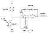
- FIG. 6 shows an outline of a circuit connected to the MCT element in the MCT detector unit.
- the MCT element is connected to a constant current source for supplying a bias current to the element, and MCT detection is performed based on the amount of decrease in the resistance value of the element due to light incident on the MCT element.
- the amount of infrared light incident on the instrument unit is required.
- the resistance signal obtained from the MCT detection element is first cut off a component below a predetermined frequency by a high-pass filter, and then the amplification circuit. It is amplified by.
- the amplified signal is sent as a photometric signal to a data processing unit (not shown) including a computer such as a personal computer.
- a data processing unit including a computer such as a personal computer.
- the amount of incident light on the MCT detector unit is derived based on the photometric signal, and an interference waveform called an interferogram is generated by plotting the temporal change of the amount of incident light.
- a temperature measuring element such as a platinum resistance temperature detector is disposed in the dewar.
- a temperature measuring element such as a platinum resistance temperature detector
- the MCT detector unit equipped with such a temperature measuring element is mounted on the FT-IR, when the MCT element becomes a predetermined temperature or higher due to evaporation of liquid nitrogen or the like, the user is notified to replenish liquid nitrogen. Or a function of protecting the MCT element by blocking the bias current supplied to the MCT element.
- the MCT element temperature is set to the predetermined value when the resistance value of the temperature measuring element exceeds a predetermined threshold value. It was judged that the temperature was over. However, there is often a slight difference between the temperature measured by the temperature measuring element and the actual temperature of the MCT element. Usually, the threshold value is set low, so that liquid nitrogen remains. Regardless, a misjudgment that notifies the user of a decrease in the remaining amount is caused.
- the threshold value is set relatively high in order to avoid this erroneous determination, when it is determined that the MCT element temperature has become equal to or higher than the predetermined threshold value, a considerable temperature increase has already occurred, and accordingly the MCT element temperature is increased. There was a case where the photometric performance was lowered due to sensitivity reduction or noise increase. As a result, when the user recognizes a notification of a decrease in the amount of remaining liquid nitrogen, it may be after multiple measurements that have already been reduced in photometric performance, especially when multiple samples are continuously analyzed by automatic analysis. It becomes a problem when measuring.
- the present invention has been made in view of the above points, and an object of the present invention is to provide a photodetector capable of detecting a decrease in the remaining amount of refrigerant such as liquid nitrogen at an appropriate timing, and the photodetector.
- the object is to provide a spectroscopic analyzer.
- the photodetector according to the present invention which has been made to solve the above problems, a) a container containing the refrigerant; b) a photoconductive detection element disposed in the container; c) a temperature measuring element disposed in the container for measuring the temperature of the photoconductive detection element; d) a photometric signal acquisition means for acquiring, as a photometric signal, a component having a predetermined frequency or higher among the resistance value of the photoconductive detection element; e) element resistance value acquisition means for acquiring the total resistance value of the photoconductive detection element as an element resistance value signal; f) determination means for determining whether or not the remaining amount of refrigerant in the container is reduced based on the time change of the temperature measured by the temperature measuring element and the time change of the element resistance value signal; It is characterized by having.
- the photodetector in the present invention detects electromagnetic energy such as infrared, ultraviolet, or visible light
- the photoconductive detection element is typically the above-described photoconductive MCT element.
- Other elements such as a photoconductive PbS (lead sulfide) element may be used as long as they are used under cooling with a refrigerant such as liquid nitrogen.
- the photodetector according to the present invention includes not only a component having a predetermined frequency or higher, which has been conventionally acquired as a photometric signal, among the resistance value of the photoconductive detection element, but also being less than the predetermined frequency.
- element resistance value acquisition means for acquiring all resistance values including components as an element resistance value signal, and is this causing a decrease in sensitivity or a decrease in photometric performance due to increased noise in the photoconductive detection element? You can know whether or not. Therefore, the determination means monitors the time change of the measured temperature by the temperature measuring element and the time change of the total resistance value of the photoconductive detection element, so that the photoconductive type starts after the measurement temperature starts to rise.
- the remaining amount of refrigerant is decreasing at an arbitrary timing until the sensitivity of the detection element decreases and the photometric performance decreases.
- the spectroscopic analyzer is: a) a light source; b) an irradiation optical system for irradiating the sample with light from the light source; c) a detector for detecting the light obtained from the interaction between the light from the light source and the sample; Have The detector is the photodetector.
- the spectroscopic analyzer according to the present invention may be any device such as an ultraviolet-visible spectrophotometer, an ultraviolet-visible near-infrared spectrophotometer, a spectrofluorophotometer, a Fourier transform infrared spectrophotometer, a Raman spectrophotometer, or the like.
- the present invention can be suitably applied particularly to a Fourier transform infrared spectrophotometer.
- an interferometer is used as the light source, and the sample is irradiated with interference light generated by the interferometer.
- the spectroscopic analysis apparatus further includes a light shielding unit that blocks a light beam incident on the photoconductive detection element when the element resistance value signal is acquired by the element resistance value acquisition unit.
- the element resistance value signal can be always acquired by the element resistance value acquiring means in a state where no light beam is incident on the photoconductive detection element. Therefore, the determination unit can determine the temporal change of the resistance value (dark resistance) independent of the amount of incident light on the photoconductive detection element, that is, the temporal change of the resistance value due to the temperature change of the element.
- the light shielding means may be provided at any position on the optical path from the light source of the spectroscopic analyzer to the photodetector.
- a light source for example, Fourier transform infrared spectroscopy
- an interferometer for example, an interferometer
- the spectroscopic analyzer is replaced with the light shielding means, d) a light-derived waveform generating means for generating a waveform indicating a time change of the element resistance signal accompanying the introduction of light into the detector; e) DC component extraction means for extracting a DC component from the waveform generated by the light-derived waveform generation means;
- the determination unit may use a time change in the intensity of the direct current component as a time change in the element resistance value signal.
- the direct current component extracted by the direct current component extraction means indicates a change in resistance value that does not depend on increase or decrease in the amount of light incident on the photoconductive detection element, that is, a change in resistance value with time due to a temperature change of the element. . Therefore, according to the spectroscopic analysis apparatus having the above-described configuration, the element resistance value can be obtained in a state in which the introduction of light into the photodetector is continued without providing the light shielding means as described above (for example, during sample measurement). Signal acquisition can be performed.
- the photodetector according to the present invention and the spectroscopic analysis apparatus including the same, it is possible to detect a decrease in the remaining amount of refrigerant such as liquid nitrogen at an appropriate timing.
- FIG. 1 is a schematic configuration diagram of a Fourier transform infrared spectrophotometer according to a first embodiment of the present invention.
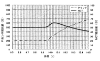
- the graph which shows the time change of the resistance value of a Pt temperature sensor and an MCT element.
- the schematic block diagram of the Fourier-transform type infrared spectrophotometer which concerns on the 2nd Example of this invention. An example of actual measurement of an MCT element resistance value signal.
- FIG. 1 is a schematic configuration diagram of a Fourier transform infrared spectrophotometer according to the present embodiment.
- the infrared light from the infrared light source 111 disposed in the hermetic chamber 110 is incident on the collimator mirror 113 through the first condenser mirror 112, and the collimator mirror. After being collimated by 113, it is divided into two by the beam splitter 114, one of which is reflected by the fixed mirror 115 and the other by the movable mirror 116, and is again guided to the same path to become interference light.
- the interference light is introduced into the sample chamber 118 via the second condenser mirror 117 disposed outside the hermetic chamber 110 and irradiated on the sample S, and then the interaction between the interference light and the sample S is performed.
- the emitted light is detected by the infrared detector unit 120 via the third condenser mirror 119.
- a signal detected by the infrared detector unit 120 is sent to the data processing unit 130 via the incident light measurement unit 122, and an interferogram is created by the incident light calculation unit 132.
- the data processing unit 130 calculates the current position of the movable mirror 116 based on data from a control interferometer (not shown). Information on the current position is sent to the control unit 140 and used for driving control of the movable mirror 116 and the like.
- the infrared detector unit 120 includes an MCT element 120a that detects the interference light (corresponding to a photoconductive detection element in the present invention), and a dewar 120b (container in the present invention) that contains a refrigerant for cooling the MCT element 120a. And a platinum resistance thermometer 120c (corresponding to the temperature measuring element in the present invention) provided in the dewar 120b.
- the MCT element 120a is connected to the circuit shown in FIG.
- a constant current source for supplying a bias current is connected to the MCT element 120a.
- the resistance value of the element 120a changes, and a voltage corresponding to the change in the resistance value is input to the incident light measurement unit 122 (corresponding to the photometric signal acquisition means in the present invention).
- the signal input to the incident light measuring unit 122 passes through the high-pass filter 122a and the amplifier circuit 122b shown in FIG. 2, so that only an AC component having a certain frequency or higher is amplified and output as a photometric signal.
- the amount of change in the resistance value of the MCT element 120a varies depending on the temperature of the element. However, if the remaining amount of the refrigerant in the dewar 120b is sufficient, the MCT element 120a is cooled to a constant temperature. The interference light can be detected with sensitivity.
- the same signal as that of the incident light measurement unit 122 is input to the detection element resistance measurement unit 121 (corresponding to the element resistance value acquisition unit in the present invention), but the signal is input to the amplifier circuit without passing through the high-pass filter. Accordingly, the input signal is amplified as an element resistance value signal including a direct current component and sent to the data processing unit 130.
- a detection element resistance calculation unit 131 in the data processing unit 130 calculates an element resistance value (total resistance value) of the MCT element 120a based on the element resistance value signal.
- the temperature measuring element resistance measuring unit 123 measures the temperature measuring resistance value signal of the platinum temperature measuring resistor 120 c and sends the temperature measuring resistance value signal to the data processing unit 130.
- a temperature measuring element resistance calculation unit 133 in the data processing unit 130 calculates the resistance value of the platinum resistance temperature detector 120c based on the temperature measurement resistance value signal.
- the control unit 140 operates the blocking mechanism driving unit 150 to move the light beam blocking mechanism 151 composed of a light shielding plate or the like in front of the MCT element 120a (the blocking mechanism driving unit 150 and the beam blocking mechanism 151 are the same in the present invention). Corresponds to light shielding means).
- the element resistance value (dark resistance) becomes a constant value. Since the dark resistance changes depending on the element temperature, a change in the element temperature can be estimated by measuring the dark resistance.
- the element resistance value (dark resistance) and the resistance value of the platinum resistance temperature detector are measured automatically or periodically according to a user instruction between sample measurements, and are stored in the data processing unit 130.
- FIG. 3 is a graph of the resistance value (dark resistance) of the MCT element 120a and the measured value of the resistance value of the platinum resistance thermometer 120c, with the vertical axis representing the resistance value and the horizontal axis representing the liquid nitrogen retention time.
- the resistance value of the MCT element 120a gradually increases from around 9.92 hours, reaches a peak around 10.04 to 10.06 hours, and then gradually decreases. This increase in resistance value is due to the physical properties of the MCT element, and has a peak of the element resistance value at a temperature slightly higher than the temperature of liquid nitrogen (77 K).
- the MCT element 120a detects the interference signal with high sensitivity in the holding time range of 9.94 to 10.24 hours.
- the holding time exceeds 10.24 hours, the element resistance value becomes lower than that in a state where the remaining amount of liquid nitrogen is sufficient (time before 9.94 hours), and the sensitivity of the MCT element 120a also decreases.
- the resistance value of the platinum resistance thermometer 120c has gradually increased from around 9.96 hours, but the time to start increasing is slightly slower than the measurement result of the element resistance value. This is because the temperature measuring position of the platinum resistance thermometer 120c is inside the dewar 120b and the temperature is not measured in contact with the MCT element 120a. Because of this time delay, it is difficult to use this resistance value for accurate temperature measurement, but since it continues to rise over time, the temperature of the element decreases due to a decrease in the remaining amount of liquid nitrogen. It can be used to determine whether or not it is rising.
- a refrigerant remaining amount determination unit 134 (corresponding to a determination unit in the present invention) in the data processing unit 130 determines whether or not there is a possibility that the refrigerant remaining amount is lowered based on these two resistance value changes. In the example of FIG. 3, when both the element resistance value and the resistance value of the platinum resistance temperature detector exceed respective threshold values set in advance, it is determined that the remaining amount of refrigerant is reduced. When the remaining refrigerant amount determining unit 134 determines that the remaining refrigerant amount is decreasing, the data processing unit 130 notifies the control unit 140 that the remaining refrigerant amount has decreased, and the control unit 140 displays a replenishment timing signal on a display or the like.
- the MCT element 120a when the temperature starts to rise, the element resistance value temporarily rises, and the detection sensitivity of the interference signal of the MCT element 120a also increases. Therefore, in the determination of the refrigerant remaining amount decrease by the element resistance value, the determination is not performed while the element resistance value is increasing, and the fact that the remaining amount of refrigerant has decreased when the element resistance value decreases and falls below the threshold value. You may make it notify.
- the resistance value of the MCT element 120a it is possible to accurately grasp the change in the element temperature of the MCT element 120a. Furthermore, by measuring the resistance value of the platinum resistance thermometer 120c, it can be confirmed whether the change in the element resistance value is due to an increase in the element temperature or due to other factors. As a result, a decrease in the remaining amount of liquid nitrogen can be detected without causing an erroneous determination, so the user is notified of a decrease in the remaining amount of refrigerant at an appropriate timing or supplied to the MCT element 120a as necessary.
- the device can be protected by cutting off the bias current.
- the light beam blocking mechanism 151 is installed immediately before the MCT element 120a. However, if the light beam incident on the MCT element 120a from the infrared light source 111 can be blocked, the light beam blocking mechanism 151 is placed in front of and behind the sample chamber 180 or in the airtight chamber 110. It may be arranged in such a manner. In addition, if the amount of light incident on the MCT element is constant, the element resistance value is measured without blocking the light beam by the light beam blocking mechanism, and a decrease in the refrigerant is determined based on the change over time based on the change over time. Can also be determined.
- FIG. 4 is a schematic configuration diagram of a Fourier transform infrared spectrophotometer according to the present embodiment.
- the light beam blocking mechanism is not provided, and the light-derived waveform generation unit 236 and the DC component extraction unit 235 are provided in the data processing unit 230. Since other configurations are the same as those of the first embodiment, description thereof will be omitted as appropriate.
- the element resistance value of the MCT element 220a is measured simultaneously with the analysis of the sample S.
- the incident light measurement unit 222 obtains a photometry signal of the sample S
- the detection element resistance measurement unit 221 obtains an element resistance value signal.
- the light-derived waveform generation unit 236 of the data processing unit 230 generates a waveform indicating a time change of the element resistance value signal from the data.
- FIG. 5 is an example of a waveform generated by the light-derived waveform generation unit 236, which is an actual measurement value of the element resistance value signal.
- the vertical axis represents the voltage value of the element resistance value signal
- the horizontal axis represents the optical path difference between the movable mirror 216 and the fixed mirror 215.
- the optical path difference becomes zero (the reflected light of the movable mirror 216 and the reflected light of the fixed mirror 215 have the same phase), and the incident light is the strongest (the element resistance value is the highest).
- the optical path difference is 1 ⁇ 2 of the wavelength ⁇ of the infrared light source (the reflected light of the movable mirror 216 and the reflected light of the fixed mirror 215 have opposite phases), which is equivalent to the case where the incident light is blocked. Therefore, the element resistance value signal at the position where the optical path difference is ⁇ / 2 is substantially equal to the dark resistance in the first embodiment.
- the data processing unit 230 receives the position data of the movable mirror 216 from a control interferometer (not shown), and sends the position data to the DC component extraction unit 235. Based on the position data, the DC component extraction unit 235 extracts the element resistance value when the optical path difference is ⁇ / 2 from the waveform indicating the time change of the element resistance value signal, and stores it in the data processing unit 230.
- the measurement data of the element resistance value is accumulated in the data processing unit 230, and a graph of the resistance change with time similar to FIG. 3 described in the first embodiment is obtained. Can do.
- the refrigerant remaining amount determining unit 234 of the data processing unit 230 determines whether or not the remaining amount of refrigerant is decreasing based on the element resistance value and the resistance value of the platinum resistance temperature detector 220c. If it is determined that the remaining amount of refrigerant is decreasing, the data processing unit 230 notifies the control unit 240 of a decrease in the remaining amount of refrigerant, and the control unit 240 outputs a replenishment timing signal to a display device (not shown) such as a display. Then, the user is notified of a decrease in the remaining refrigerant amount.
- the moving range of the moving mirror includes the position where the optical path difference between the moving mirror and the fixed mirror is ⁇ / 2, so that the MCT element 220a can be measured simultaneously with the measurement of the sample.
- An element resistance value dark resistance
- a decrease in the remaining refrigerant amount can be determined without erroneous determination based on the element resistance value and the resistance value of the temperature measuring element.
- the element resistance value can be measured simultaneously with the measurement of the spectral characteristics of the sample, it is not necessary for the user to perform an additional measurement for confirming the remaining amount of the refrigerant, and there is no burden. Furthermore, it is possible to determine a decrease in the remaining refrigerant amount without interrupting the measurement.
- the MCT element is used for the photodetector, but a PbS element may be used as the detection element.
- the wavelength range in which the element has sensitivity, the operating temperature, the type of refrigerant used, the change in resistance value, and the like are different from those of the MCT element, but the element resistance value and temperature measurement are the same as in the first and second embodiments.
- Each element resistance value can be measured to determine a decrease in the remaining refrigerant amount.
- the RC circuit was used as a high pass filter of an incident light measurement part, as shown to FIG. 2, 6, another high pass filter may be used.
- the non-inverting amplifier circuit is used in the incident light measurement unit and the detection element resistance measurement unit.
- any other amplification circuit can be used as long as it can amplify the DC component. May be used.
- the photodetector according to the present invention can be applied to a dispersive spectrophotometer in addition to the Fourier transform spectrophotometer.
Landscapes
- Physics & Mathematics (AREA)
- Spectroscopy & Molecular Physics (AREA)
- General Physics & Mathematics (AREA)
- Spectrometry And Color Measurement (AREA)
- Photometry And Measurement Of Optical Pulse Characteristics (AREA)
- Investigating Or Analysing Materials By Optical Means (AREA)
Abstract
L'invention concerne un photodétecteur comprenant : un récipient (120b) contenant un fluide frigorigène ; un élément de détection de type de photoconduction (120a) disposé dans le récipient ; un élément de mesure de température (120c) disposé dans le récipient pour mesurer la température de l'élément de détection de type de photoconduction ; un moyen d'acquisition de signal photométrique (122) pour acquérir, en tant que signal photométrique, une composante d'une valeur de résistance de l'élément de détection de type de photoconduction ayant une fréquence au moins égale à une fréquence prescrite ; un moyen d'acquisition de valeur de résistance d'élément (121) pour acquérir, en tant que signal de valeur de résistance d'élément, la valeur de résistance totale de l'élément de détection de type de photoconduction ; et un moyen de détermination (134) pour déterminer si la quantité résiduelle du fluide frigorigène dans le récipient a diminué, sur la base d'une variation au cours du temps dans la température mesurée par l'élément de mesure de température et d'une variation au cours du temps dans le signal de valeur de résistance d'élément. Il est ainsi possible de détecter une diminution de la quantité résiduelle d'un fluide frigorigène tel que de l'azote liquide avec une synchronisation appropriée.
Priority Applications (1)
| Application Number | Priority Date | Filing Date | Title |
|---|---|---|---|
| JP2019513645A JP6743971B2 (ja) | 2017-04-18 | 2018-04-17 | 光検出器及びそれを備えた分光分析装置 |
Applications Claiming Priority (2)
| Application Number | Priority Date | Filing Date | Title |
|---|---|---|---|
| JP2017-081793 | 2017-04-18 | ||
| JP2017081793 | 2017-04-18 |
Publications (1)
| Publication Number | Publication Date |
|---|---|
| WO2018194048A1 true WO2018194048A1 (fr) | 2018-10-25 |
Family
ID=63856637
Family Applications (1)
| Application Number | Title | Priority Date | Filing Date |
|---|---|---|---|
| PCT/JP2018/015820 Ceased WO2018194048A1 (fr) | 2017-04-18 | 2018-04-17 | Photodétecteur et dispositif d'analyse photométrique le comprenant |
Country Status (2)
| Country | Link |
|---|---|
| JP (1) | JP6743971B2 (fr) |
| WO (1) | WO2018194048A1 (fr) |
Citations (6)
| Publication number | Priority date | Publication date | Assignee | Title |
|---|---|---|---|---|
| JPS58125275U (ja) * | 1982-02-19 | 1983-08-25 | ソニー株式会社 | デイスク再生装置 |
| JPS6338121A (ja) * | 1986-08-04 | 1988-02-18 | Jeol Ltd | サ−モグラフイ−装置における赤外線検出部異常検知方式 |
| JPS6353426A (ja) * | 1986-08-25 | 1988-03-07 | Fujitsu Ltd | 液体窒素の残量検出装置 |
| JPH05203489A (ja) * | 1992-01-29 | 1993-08-10 | Nec Corp | 光伝導型赤外線検知装置 |
| US20110043638A1 (en) * | 2008-04-25 | 2011-02-24 | Thales | Optronic Infrared System with Predictive Maintenance Following a Sudden Drift |
| JP3206138U (ja) * | 2016-06-21 | 2016-09-01 | 株式会社島津製作所 | 検出器システム及びそれを用いた赤外顕微鏡 |
-
2018
- 2018-04-17 WO PCT/JP2018/015820 patent/WO2018194048A1/fr not_active Ceased
- 2018-04-17 JP JP2019513645A patent/JP6743971B2/ja active Active
Patent Citations (6)
| Publication number | Priority date | Publication date | Assignee | Title |
|---|---|---|---|---|
| JPS58125275U (ja) * | 1982-02-19 | 1983-08-25 | ソニー株式会社 | デイスク再生装置 |
| JPS6338121A (ja) * | 1986-08-04 | 1988-02-18 | Jeol Ltd | サ−モグラフイ−装置における赤外線検出部異常検知方式 |
| JPS6353426A (ja) * | 1986-08-25 | 1988-03-07 | Fujitsu Ltd | 液体窒素の残量検出装置 |
| JPH05203489A (ja) * | 1992-01-29 | 1993-08-10 | Nec Corp | 光伝導型赤外線検知装置 |
| US20110043638A1 (en) * | 2008-04-25 | 2011-02-24 | Thales | Optronic Infrared System with Predictive Maintenance Following a Sudden Drift |
| JP3206138U (ja) * | 2016-06-21 | 2016-09-01 | 株式会社島津製作所 | 検出器システム及びそれを用いた赤外顕微鏡 |
Also Published As
| Publication number | Publication date |
|---|---|
| JPWO2018194048A1 (ja) | 2019-11-07 |
| JP6743971B2 (ja) | 2020-08-19 |
Similar Documents
| Publication | Publication Date | Title |
|---|---|---|
| US20240410822A1 (en) | Reference switch architectures for noncontact sensing of substances | |
| US6741348B2 (en) | Ultrasensitive spectrophotometer | |
| US7903252B2 (en) | Noise cancellation in fourier transform spectrophotometry | |
| US9557261B2 (en) | Spectroscopic analysis method and spectroscopic analyzer | |
| JP2014510291A (ja) | 分光分析器 | |
| CA2479334A1 (fr) | Analyseur haute vitesse utilisant le rayonnement infrarouge proche transmis a travers les echantillons epais d'un materiau optiquement dense | |
| KR20150037977A (ko) | 이중 분광계 | |
| CN103221802A (zh) | 分光光度计 | |
| JP6743971B2 (ja) | 光検出器及びそれを備えた分光分析装置 | |
| JP2015052531A (ja) | 分光器の波長校正方法 | |
| US20120307240A1 (en) | Spectrophotometer and method for determining performance thereof | |
| CN108027317A (zh) | 参考方案中的测量时间分布 | |
| US20130188182A1 (en) | Raman Apparatus and Method for Real Time Calibration Thereof | |
| US11933675B2 (en) | System and method for multi-channel pyrometer allowing non-contact temperature measurements down to 800 K on the microsecond scale | |
| JP2015087108A (ja) | フーリエ変換分光光度計及び光量制御方法 | |
| Wiesent et al. | Limits of IR-spectrometers based on linear variable filters and detector arrays | |
| JP5790596B2 (ja) | フォトダイオードアレイ検出器 | |
| JP3755997B2 (ja) | 液体クロマトグラフ | |
| CN106353262B (zh) | 原子吸收测量方法以及测量装置 | |
| JP5949613B2 (ja) | 分光光度計 | |
| EP4206625A1 (fr) | Procédé et dispositif de réglage d'un mode de mesure dans un dispositif de spectroscopie raman portable | |
| JP5924166B2 (ja) | 波長可変単色光光源 | |
| RU2580896C1 (ru) | Дисперсионный спектрометр | |
| AU2015100564A4 (en) | Spectrometer | |
| Liu et al. | UV focal plane array device relative spectral response measurement technology research |
Legal Events
| Date | Code | Title | Description |
|---|---|---|---|
| 121 | Ep: the epo has been informed by wipo that ep was designated in this application |
Ref document number: 18788215 Country of ref document: EP Kind code of ref document: A1 |
|
| ENP | Entry into the national phase |
Ref document number: 2019513645 Country of ref document: JP Kind code of ref document: A |
|
| NENP | Non-entry into the national phase |
Ref country code: DE |
|
| 122 | Ep: pct application non-entry in european phase |
Ref document number: 18788215 Country of ref document: EP Kind code of ref document: A1 |