WO2018198429A1 - 排ガス浄化システム及び自動推進車両 - Google Patents
排ガス浄化システム及び自動推進車両 Download PDFInfo
- Publication number
- WO2018198429A1 WO2018198429A1 PCT/JP2017/045815 JP2017045815W WO2018198429A1 WO 2018198429 A1 WO2018198429 A1 WO 2018198429A1 JP 2017045815 W JP2017045815 W JP 2017045815W WO 2018198429 A1 WO2018198429 A1 WO 2018198429A1
- Authority
- WO
- WIPO (PCT)
- Prior art keywords
- exhaust gas
- gas purification
- purification system
- set value
- amount
- Prior art date
- Legal status (The legal status is an assumption and is not a legal conclusion. Google has not performed a legal analysis and makes no representation as to the accuracy of the status listed.)
- Ceased
Links
Images


Classifications
-
- F—MECHANICAL ENGINEERING; LIGHTING; HEATING; WEAPONS; BLASTING
- F01—MACHINES OR ENGINES IN GENERAL; ENGINE PLANTS IN GENERAL; STEAM ENGINES
- F01N—GAS-FLOW SILENCERS OR EXHAUST APPARATUS FOR MACHINES OR ENGINES IN GENERAL; GAS-FLOW SILENCERS OR EXHAUST APPARATUS FOR INTERNAL-COMBUSTION ENGINES
- F01N11/00—Monitoring or diagnostic devices for exhaust-gas treatment apparatus
- F01N11/007—Monitoring or diagnostic devices for exhaust-gas treatment apparatus the diagnostic devices measuring oxygen or air concentration downstream of the exhaust apparatus
-
- B—PERFORMING OPERATIONS; TRANSPORTING
- B01—PHYSICAL OR CHEMICAL PROCESSES OR APPARATUS IN GENERAL
- B01D—SEPARATION
- B01D53/00—Separation of gases or vapours; Recovering vapours of volatile solvents from gases; Chemical or biological purification of waste gases, e.g. engine exhaust gases, smoke, fumes, flue gases, aerosols
- B01D53/34—Chemical or biological purification of waste gases
- B01D53/92—Chemical or biological purification of waste gases of engine exhaust gases
- B01D53/94—Chemical or biological purification of waste gases of engine exhaust gases by catalytic processes
- B01D53/9404—Removing only nitrogen compounds
- B01D53/9409—Nitrogen oxides
- B01D53/9431—Processes characterised by a specific device
-
- F—MECHANICAL ENGINEERING; LIGHTING; HEATING; WEAPONS; BLASTING
- F01—MACHINES OR ENGINES IN GENERAL; ENGINE PLANTS IN GENERAL; STEAM ENGINES
- F01N—GAS-FLOW SILENCERS OR EXHAUST APPARATUS FOR MACHINES OR ENGINES IN GENERAL; GAS-FLOW SILENCERS OR EXHAUST APPARATUS FOR INTERNAL-COMBUSTION ENGINES
- F01N3/00—Exhaust or silencing apparatus having means for purifying, rendering innocuous, or otherwise treating exhaust
- F01N3/08—Exhaust or silencing apparatus having means for purifying, rendering innocuous, or otherwise treating exhaust for rendering innocuous
- F01N3/0807—Exhaust or silencing apparatus having means for purifying, rendering innocuous, or otherwise treating exhaust for rendering innocuous by using absorbents or adsorbents
- F01N3/0814—Exhaust or silencing apparatus having means for purifying, rendering innocuous, or otherwise treating exhaust for rendering innocuous by using absorbents or adsorbents combined with catalytic converters, e.g. NOx absorption/storage reduction catalysts
-
- F—MECHANICAL ENGINEERING; LIGHTING; HEATING; WEAPONS; BLASTING
- F01—MACHINES OR ENGINES IN GENERAL; ENGINE PLANTS IN GENERAL; STEAM ENGINES
- F01N—GAS-FLOW SILENCERS OR EXHAUST APPARATUS FOR MACHINES OR ENGINES IN GENERAL; GAS-FLOW SILENCERS OR EXHAUST APPARATUS FOR INTERNAL-COMBUSTION ENGINES
- F01N3/00—Exhaust or silencing apparatus having means for purifying, rendering innocuous, or otherwise treating exhaust
- F01N3/08—Exhaust or silencing apparatus having means for purifying, rendering innocuous, or otherwise treating exhaust for rendering innocuous
- F01N3/0807—Exhaust or silencing apparatus having means for purifying, rendering innocuous, or otherwise treating exhaust for rendering innocuous by using absorbents or adsorbents
- F01N3/0828—Exhaust or silencing apparatus having means for purifying, rendering innocuous, or otherwise treating exhaust for rendering innocuous by using absorbents or adsorbents characterised by the absorbed or adsorbed substances
- F01N3/0842—Nitrogen oxides
-
- F—MECHANICAL ENGINEERING; LIGHTING; HEATING; WEAPONS; BLASTING
- F01—MACHINES OR ENGINES IN GENERAL; ENGINE PLANTS IN GENERAL; STEAM ENGINES
- F01N—GAS-FLOW SILENCERS OR EXHAUST APPARATUS FOR MACHINES OR ENGINES IN GENERAL; GAS-FLOW SILENCERS OR EXHAUST APPARATUS FOR INTERNAL-COMBUSTION ENGINES
- F01N3/00—Exhaust or silencing apparatus having means for purifying, rendering innocuous, or otherwise treating exhaust
- F01N3/08—Exhaust or silencing apparatus having means for purifying, rendering innocuous, or otherwise treating exhaust for rendering innocuous
- F01N3/10—Exhaust or silencing apparatus having means for purifying, rendering innocuous, or otherwise treating exhaust for rendering innocuous by thermal or catalytic conversion of noxious components of exhaust
- F01N3/18—Exhaust or silencing apparatus having means for purifying, rendering innocuous, or otherwise treating exhaust for rendering innocuous by thermal or catalytic conversion of noxious components of exhaust characterised by methods of operation; Control
- F01N3/20—Exhaust or silencing apparatus having means for purifying, rendering innocuous, or otherwise treating exhaust for rendering innocuous by thermal or catalytic conversion of noxious components of exhaust characterised by methods of operation; Control specially adapted for catalytic conversion
- F01N3/206—Adding periodically or continuously substances to exhaust gases for promoting purification, e.g. catalytic material in liquid form, NOx reducing agents
- F01N3/2066—Selective catalytic reduction [SCR]
-
- F—MECHANICAL ENGINEERING; LIGHTING; HEATING; WEAPONS; BLASTING
- F01—MACHINES OR ENGINES IN GENERAL; ENGINE PLANTS IN GENERAL; STEAM ENGINES
- F01N—GAS-FLOW SILENCERS OR EXHAUST APPARATUS FOR MACHINES OR ENGINES IN GENERAL; GAS-FLOW SILENCERS OR EXHAUST APPARATUS FOR INTERNAL-COMBUSTION ENGINES
- F01N2330/00—Structure of catalyst support or particle filter
- F01N2330/06—Ceramic, e.g. monoliths
-
- F—MECHANICAL ENGINEERING; LIGHTING; HEATING; WEAPONS; BLASTING
- F01—MACHINES OR ENGINES IN GENERAL; ENGINE PLANTS IN GENERAL; STEAM ENGINES
- F01N—GAS-FLOW SILENCERS OR EXHAUST APPARATUS FOR MACHINES OR ENGINES IN GENERAL; GAS-FLOW SILENCERS OR EXHAUST APPARATUS FOR INTERNAL-COMBUSTION ENGINES
- F01N2370/00—Selection of materials for exhaust purification
- F01N2370/02—Selection of materials for exhaust purification used in catalytic reactors
-
- F—MECHANICAL ENGINEERING; LIGHTING; HEATING; WEAPONS; BLASTING
- F01—MACHINES OR ENGINES IN GENERAL; ENGINE PLANTS IN GENERAL; STEAM ENGINES
- F01N—GAS-FLOW SILENCERS OR EXHAUST APPARATUS FOR MACHINES OR ENGINES IN GENERAL; GAS-FLOW SILENCERS OR EXHAUST APPARATUS FOR INTERNAL-COMBUSTION ENGINES
- F01N2510/00—Surface coverings
- F01N2510/06—Surface coverings for exhaust purification, e.g. catalytic reaction
-
- F—MECHANICAL ENGINEERING; LIGHTING; HEATING; WEAPONS; BLASTING
- F01—MACHINES OR ENGINES IN GENERAL; ENGINE PLANTS IN GENERAL; STEAM ENGINES
- F01N—GAS-FLOW SILENCERS OR EXHAUST APPARATUS FOR MACHINES OR ENGINES IN GENERAL; GAS-FLOW SILENCERS OR EXHAUST APPARATUS FOR INTERNAL-COMBUSTION ENGINES
- F01N2550/00—Monitoring or diagnosing the deterioration of exhaust systems
- F01N2550/02—Catalytic activity of catalytic converters
-
- F—MECHANICAL ENGINEERING; LIGHTING; HEATING; WEAPONS; BLASTING
- F01—MACHINES OR ENGINES IN GENERAL; ENGINE PLANTS IN GENERAL; STEAM ENGINES
- F01N—GAS-FLOW SILENCERS OR EXHAUST APPARATUS FOR MACHINES OR ENGINES IN GENERAL; GAS-FLOW SILENCERS OR EXHAUST APPARATUS FOR INTERNAL-COMBUSTION ENGINES
- F01N2560/00—Exhaust systems with means for detecting or measuring exhaust gas components or characteristics
- F01N2560/02—Exhaust systems with means for detecting or measuring exhaust gas components or characteristics the means being an exhaust gas sensor
- F01N2560/026—Exhaust systems with means for detecting or measuring exhaust gas components or characteristics the means being an exhaust gas sensor for measuring or detecting NOx
-
- F—MECHANICAL ENGINEERING; LIGHTING; HEATING; WEAPONS; BLASTING
- F01—MACHINES OR ENGINES IN GENERAL; ENGINE PLANTS IN GENERAL; STEAM ENGINES
- F01N—GAS-FLOW SILENCERS OR EXHAUST APPARATUS FOR MACHINES OR ENGINES IN GENERAL; GAS-FLOW SILENCERS OR EXHAUST APPARATUS FOR INTERNAL-COMBUSTION ENGINES
- F01N2900/00—Details of electrical control or of the monitoring of the exhaust gas treating apparatus
- F01N2900/04—Methods of control or diagnosing
- F01N2900/0416—Methods of control or diagnosing using the state of a sensor, e.g. of an exhaust gas sensor
-
- F—MECHANICAL ENGINEERING; LIGHTING; HEATING; WEAPONS; BLASTING
- F01—MACHINES OR ENGINES IN GENERAL; ENGINE PLANTS IN GENERAL; STEAM ENGINES
- F01N—GAS-FLOW SILENCERS OR EXHAUST APPARATUS FOR MACHINES OR ENGINES IN GENERAL; GAS-FLOW SILENCERS OR EXHAUST APPARATUS FOR INTERNAL-COMBUSTION ENGINES
- F01N2900/00—Details of electrical control or of the monitoring of the exhaust gas treating apparatus
- F01N2900/04—Methods of control or diagnosing
- F01N2900/0422—Methods of control or diagnosing measuring the elapsed time
-
- F—MECHANICAL ENGINEERING; LIGHTING; HEATING; WEAPONS; BLASTING
- F01—MACHINES OR ENGINES IN GENERAL; ENGINE PLANTS IN GENERAL; STEAM ENGINES
- F01N—GAS-FLOW SILENCERS OR EXHAUST APPARATUS FOR MACHINES OR ENGINES IN GENERAL; GAS-FLOW SILENCERS OR EXHAUST APPARATUS FOR INTERNAL-COMBUSTION ENGINES
- F01N2900/00—Details of electrical control or of the monitoring of the exhaust gas treating apparatus
- F01N2900/06—Parameters used for exhaust control or diagnosing
- F01N2900/08—Parameters used for exhaust control or diagnosing said parameters being related to the engine
-
- F—MECHANICAL ENGINEERING; LIGHTING; HEATING; WEAPONS; BLASTING
- F01—MACHINES OR ENGINES IN GENERAL; ENGINE PLANTS IN GENERAL; STEAM ENGINES
- F01N—GAS-FLOW SILENCERS OR EXHAUST APPARATUS FOR MACHINES OR ENGINES IN GENERAL; GAS-FLOW SILENCERS OR EXHAUST APPARATUS FOR INTERNAL-COMBUSTION ENGINES
- F01N2900/00—Details of electrical control or of the monitoring of the exhaust gas treating apparatus
- F01N2900/06—Parameters used for exhaust control or diagnosing
- F01N2900/10—Parameters used for exhaust control or diagnosing said parameters being related to the vehicle or its components
- F01N2900/102—Travelling distance
-
- F—MECHANICAL ENGINEERING; LIGHTING; HEATING; WEAPONS; BLASTING
- F01—MACHINES OR ENGINES IN GENERAL; ENGINE PLANTS IN GENERAL; STEAM ENGINES
- F01N—GAS-FLOW SILENCERS OR EXHAUST APPARATUS FOR MACHINES OR ENGINES IN GENERAL; GAS-FLOW SILENCERS OR EXHAUST APPARATUS FOR INTERNAL-COMBUSTION ENGINES
- F01N2900/00—Details of electrical control or of the monitoring of the exhaust gas treating apparatus
- F01N2900/06—Parameters used for exhaust control or diagnosing
- F01N2900/14—Parameters used for exhaust control or diagnosing said parameters being related to the exhaust gas
- F01N2900/1411—Exhaust gas flow rate, e.g. mass flow rate or volumetric flow rate
-
- F—MECHANICAL ENGINEERING; LIGHTING; HEATING; WEAPONS; BLASTING
- F01—MACHINES OR ENGINES IN GENERAL; ENGINE PLANTS IN GENERAL; STEAM ENGINES
- F01N—GAS-FLOW SILENCERS OR EXHAUST APPARATUS FOR MACHINES OR ENGINES IN GENERAL; GAS-FLOW SILENCERS OR EXHAUST APPARATUS FOR INTERNAL-COMBUSTION ENGINES
- F01N3/00—Exhaust or silencing apparatus having means for purifying, rendering innocuous, or otherwise treating exhaust
- F01N3/02—Exhaust or silencing apparatus having means for purifying, rendering innocuous, or otherwise treating exhaust for cooling, or for removing solid constituents of, exhaust
- F01N3/021—Exhaust or silencing apparatus having means for purifying, rendering innocuous, or otherwise treating exhaust for cooling, or for removing solid constituents of, exhaust by means of filters
- F01N3/033—Exhaust or silencing apparatus having means for purifying, rendering innocuous, or otherwise treating exhaust for cooling, or for removing solid constituents of, exhaust by means of filters in combination with other devices
- F01N3/035—Exhaust or silencing apparatus having means for purifying, rendering innocuous, or otherwise treating exhaust for cooling, or for removing solid constituents of, exhaust by means of filters in combination with other devices with catalytic reactors
-
- F—MECHANICAL ENGINEERING; LIGHTING; HEATING; WEAPONS; BLASTING
- F01—MACHINES OR ENGINES IN GENERAL; ENGINE PLANTS IN GENERAL; STEAM ENGINES
- F01N—GAS-FLOW SILENCERS OR EXHAUST APPARATUS FOR MACHINES OR ENGINES IN GENERAL; GAS-FLOW SILENCERS OR EXHAUST APPARATUS FOR INTERNAL-COMBUSTION ENGINES
- F01N3/00—Exhaust or silencing apparatus having means for purifying, rendering innocuous, or otherwise treating exhaust
- F01N3/08—Exhaust or silencing apparatus having means for purifying, rendering innocuous, or otherwise treating exhaust for rendering innocuous
- F01N3/10—Exhaust or silencing apparatus having means for purifying, rendering innocuous, or otherwise treating exhaust for rendering innocuous by thermal or catalytic conversion of noxious components of exhaust
- F01N3/24—Exhaust or silencing apparatus having means for purifying, rendering innocuous, or otherwise treating exhaust for rendering innocuous by thermal or catalytic conversion of noxious components of exhaust characterised by constructional aspects of converting apparatus
- F01N3/28—Construction of catalytic reactors
- F01N3/2803—Construction of catalytic reactors characterised by structure, by material or by manufacturing of catalyst support
- F01N3/2825—Ceramics
- F01N3/2828—Ceramic multi-channel monoliths, e.g. honeycombs
-
- Y—GENERAL TAGGING OF NEW TECHNOLOGICAL DEVELOPMENTS; GENERAL TAGGING OF CROSS-SECTIONAL TECHNOLOGIES SPANNING OVER SEVERAL SECTIONS OF THE IPC; TECHNICAL SUBJECTS COVERED BY FORMER USPC CROSS-REFERENCE ART COLLECTIONS [XRACs] AND DIGESTS
- Y02—TECHNOLOGIES OR APPLICATIONS FOR MITIGATION OR ADAPTATION AGAINST CLIMATE CHANGE
- Y02T—CLIMATE CHANGE MITIGATION TECHNOLOGIES RELATED TO TRANSPORTATION
- Y02T10/00—Road transport of goods or passengers
- Y02T10/10—Internal combustion engine [ICE] based vehicles
- Y02T10/40—Engine management systems
Definitions
- the present invention relates to an exhaust gas purification system and an automatic propulsion vehicle.
- An automatic propulsion vehicle equipped with a combustion engine such as a diesel engine purifies exhaust gas discharged from the combustion engine so as to be released to the atmosphere by one or more exhaust gas purification catalysts. Therefore, when the performance of the exhaust gas purification catalyst deteriorates, the concentration of harmful components in the exhaust gas released to the atmosphere, for example, the concentration of nitrogen oxide (NO x ) increases.
- a combustion engine such as a diesel engine
- NO x nitrogen oxide
- Japanese Patent Application Laid-Open No. 2000-18023 describes a diagnostic device that determines the degree of deterioration of a NO x storage catalyst.
- this diagnostic system within a period of between one rich spike and the next rich spike, definitive when the concentration of NO x at the outlet portion of the NO x storage catalyst is the lowest value, the outlet portion of the NO x storage catalyst on the basis of the ratio of the concentration of NO x at the inlet portion of the NO x concentration and the NO x storage catalyst, the determining the degree of deterioration of the NO x storage catalyst.
- JP 2012-36856 discloses a method for determining the degree of deterioration of a diesel oxidation catalyst for an exhaust gas purification system including a diesel oxidation catalyst and a selective reduction catalyst that is installed downstream of the diesel oxidation catalyst and reduces NO x to nitrogen.
- a diagnostic device for doing this is described.
- This diagnostic apparatus is configured such that the ratio of the detected value output from the NO x sensor installed downstream of the selective reduction catalyst to the NO x amount in the exhaust gas upstream of the diesel oxidation catalyst and the exhaust gas on the downstream side of the selective reduction catalyst.
- Sensor characteristic storage means for storing the relationship with the NO 2 ratio.
- the NO x amount in the exhaust gas upstream of the diesel oxidation catalyst is a value calculated from the NO x concentration in the exhaust gas upstream of the diesel oxidation catalyst and the supply air or exhaust gas flow rate. Further, the concentration of NO x in the exhaust gas on the upstream side of the diesel oxidation catalyst, the operating state of the diesel engine, for example, the accelerator opening degree and the rotational speed, the relationship between the concentration of NO x in the exhaust gas on the upstream side of the diesel oxidation catalyst It is a value obtained by referring to the operation state of the diesel engine in the described map.
- the NO 2 ratio is the ratio of the amount of nitrogen dioxide (NO 2 ) in the exhaust gas downstream of the selective reduction catalyst to the amount of NO x in the exhaust gas downstream of the selective reduction catalyst.
- JP diagnostic apparatus described in 2012-36856 JP calculates the amount of NO x in the exhaust gas on the upstream side of the diesel oxidation catalyst and a driving state of the diesel engine and the air supply or exhaust flow rate, for the amount of NO x
- the ratio of the detection values output from the NO x sensor is referred to the relationship stored in the sensor characteristic storage means to calculate the NO 2 ratio in the exhaust gas on the downstream side of the selective reduction catalyst. Then, based on the NO 2 ratio, it determines the degree of deterioration of the diesel oxidation catalyst.
- JP-A-2012-219740 discloses, the air-fuel ratio switching from fuel-lean to fuel-rich, the exhaust gas passing through the catalyst, determined a reduction of the NO x concentration with the elapse of time as the NO x purification rate, the NO x It is described that the exhaust gas purification performance of a catalyst is evaluated based on the purification rate.
- an object of the present invention that the amount of the NO x exceeding the reference value provides the possibility is low exhaust gas purification technique is discharged in actual running.
- an exhaust gas purification system for purifying exhaust gas discharged from a combustion engine mounted on an automatic propulsion vehicle, comprising at least one exhaust gas purification catalyst, wherein the exhaust gas is supplied from the combustion engine.
- An exhaust gas purification device that purifies the exhaust gas so as to be released to the atmosphere, a sensor that detects a concentration of nitrogen oxides contained in the exhaust gas purified by the exhaust gas purification device, and a concentration detected by the sensor.
- an exhaust gas purification system including a processing unit that determines whether or not the performance of at least one of the one or more exhaust gas purification catalysts is maintained at a sufficient level.
- the processing unit has the one or more exhaust gas purification catalysts when the concentration detected by the sensor is less than a first set value or less than the first set value.
- An exhaust gas purification system according to the first aspect of the present invention is provided that determines that the performance of at least one of the above is maintained at a sufficient level.
- the processing unit detects the concentration detected by the sensor within a certain time interval, and the amount or flow rate of air supplied to the combustion engine within the time interval, or within the time interval.
- the amount of nitrogen oxides discharged by the automatic propulsion vehicle per unit travel distance from the amount or flow rate of the exhaust gas discharged by the combustion engine and the travel distance or travel speed of the automatic propulsion vehicle within the time interval.
- the performance of the at least one of the one or more exhaust gas purification catalysts is maintained at a sufficient level.
- the processing unit detects the concentration detected by the sensor within the time interval and the air supplied to the combustion engine within the time interval. From the amount or flow rate or the amount or flow rate of the exhaust gas discharged by the combustion engine within the time interval and the travel distance or travel speed of the automatic propulsion vehicle within the time interval, the automatic propulsion vehicle per unit travel distance The amount of nitrogen oxides discharged to the vehicle is calculated, and the automatic propulsion vehicle travels from the change in the amount of nitrogen oxides discharged per unit travel distance by the automatic propulsion vehicle with respect to the cumulative travel distance of the automatic propulsion vehicle.
- an exhaust gas purification system according to any one of the first to third aspects for estimating an accumulated travel distance at which the amount of nitrogen oxides discharged per distance reaches a third set value.
- An exhaust gas purification system determines that the at least one of the one or more exhaust gas purification catalysts needs to be replaced or that the replacement time is approaching.
- an exhaust gas purification system according to any one of the first to fifth aspects, further comprising an output unit that outputs a processing result in the processing unit.
- the combustion engine is a diesel engine
- the one or more exhaust gas purification catalysts include at least one of a storage reduction catalyst, a urea selective reduction catalyst, and a hydrocarbon selective reduction catalyst.
- an automatic propulsion vehicle including the exhaust gas purification system according to any one of the first to seventh aspects.
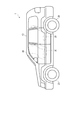
- FIG. 1 is a side view schematically showing an automatic propulsion vehicle according to an embodiment of the present invention.
- the flowchart which shows an example of the control which the exhaust gas purification system shown in FIG. 2 performs.
- the graph which shows an example of the time change of the NOx density
- FIG. 3 is a perspective view schematically showing a state in which the exhaust gas purification system shown in FIG. 2 alerts the driver that the catalyst replacement time is approaching.
- FIG. 15 is a flowchart showing another part of the control whose part is shown in FIG.
- FIG. 1 is a side view schematically showing an automatic propulsion vehicle according to an embodiment of the present invention.
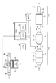
- FIG. 2 is a diagram schematically showing an example of an exhaust gas purification system that can be mounted on the automatic propulsion vehicle shown in FIG. 1.
- FIG. 1 depicts a four-wheeled vehicle (hereinafter referred to as an automobile) 1 as an example of an automatic propulsion vehicle.
- an automobile a four-wheeled vehicle
- FIG. 1 and FIG. 2 some components are omitted for easy understanding.
- the terms “front” and “rear” are used based on the traveling direction of the automobile 1, and the terms “upstream” and “downstream” are used based on the flow of exhaust gas. To do.
- FIG. 1 is a four-wheel drive vehicle equipped with a diesel engine 50 shown in FIG. 2 in front of the passenger compartment.
- the vehicle body 1 includes a vehicle main body.
- the vehicle body includes a frame and a vehicle body 10 (not shown).
- the frame and the vehicle body 10 may be integrated. That is, a monocoque structure may be adopted for the vehicle body.
- the drive unit, suspension device, acceleration device, brake device, steering device, etc. are mounted on the frame.
- the drive device includes a combustion engine, an air supply device, an exhaust device, a fuel supply device, a power transmission device, and the like.
- the combustion engine is the diesel engine 50 shown in FIG. 2, only the cylinder 51, the piston head 52, the connecting rod 53, the intake valve 54, the exhaust valve 55, and the fuel injection nozzle 56 are illustrated as components of the diesel engine 50.
- the diesel engine 50 is a four-stroke cycle diesel engine.
- the diesel engine 50 may be a two-stroke cycle diesel engine.
- the air supply device includes an air filter, an air supply pipe, and an air flow meter 60.
- the air supply device takes in air from the outside of the vehicle, removes dust and the like with an air filter, and then supplies the air to the combustion chamber of the diesel engine 50 through the air supply pipe.
- the air flow meter 60 detects the flow rate of the air flowing through the air supply pipe.
- the air supply device may further include a supercharger that can supply air with increased pressure to the combustion chamber.
- the exhaust device is the exhaust device 70 shown in FIG.
- the exhaust device 70 plays a role of purifying exhaust gas generated by combustion of fuel in the diesel engine 50, here, light oil, and reducing exhaust noise.
- the exhaust device 70 includes catalytic converters 71 and 72, a muffler 73, a muffler cutter 74, pipes 75a, 75b, 75c and 75d, and sensors 76a and 76b.
- the catalytic converters 71 and 72 and the pipe 75b constitute an exhaust gas purification device 70a that purifies the exhaust gas so as to be released into the atmosphere.
- the muffler 73, the pipe 75d, and the muffler cutter 74 constitute a silencer 70b.
- the catalytic converter 71 includes a converter body 711, an exhaust gas purifying catalyst 712, and a diesel particulate filter (DPF) 713.
- DPF diesel particulate filter
- the converter body 711 is made of, for example, a metal or an alloy.
- Converter body 711 has a hollow structure provided with an intake port and an exhaust port.
- the intake port of the converter body 711 is connected to the piston chamber of the diesel engine 50 via a pipe 75a and an exhaust manifold (not shown).
- One end of a pipe 75 b is connected to the exhaust port of the converter body 711.
- the exhaust gas purifying catalyst 712 is a straight flow type monolith catalyst.
- the exhaust gas purifying catalyst 712 is configured so that the exhaust gas supplied to the intake port of the converter body 711 passes through the through hole of the exhaust gas purifying catalyst 712 and is then supplied to the diesel particulate filter 713. Is housed inside.
- the exhaust gas purifying catalyst 712 is a diesel oxidation catalyst (DOC). According to another example, the exhaust gas purifying catalyst 712, NO x storage-reduction; a (NO x storage and reduction NSR) catalyst.
- DOC diesel oxidation catalyst
- the exhaust gas purifying catalyst 712 NO x storage-reduction; a (NO x storage and reduction NSR) catalyst.
- the exhaust gas-purifying catalyst 712 includes a monolith honeycomb substrate and a catalyst layer provided on the partition walls.
- the monolith honeycomb substrate is, for example, a pillar provided with a plurality of through holes each extending from one bottom surface to the other bottom surface.
- the monolith honeycomb substrate is made of ceramics such as cordierite and silicon carbide, for example.
- the catalyst layer is provided on the partition walls of the monolith honeycomb substrate.
- the catalyst layer may have a single layer structure or a multilayer structure.
- the catalyst layer includes, for example, a first carrier and a first noble metal element.
- the first carrier is particles made of a heat resistant material such as alumina.
- the first carrier carries the first noble metal element.
- the first carrier increases the surface area of the first noble metal and plays a role of suppressing the sintering of the first noble metal by dissipating heat generated by the catalytic reaction.
- the first noble metal element is, for example, a platinum group element such as platinum and palladium.
- the catalyst layer may contain a single noble metal element as the first noble metal element, or may contain a plurality of noble metal elements.
- the first noble metal element promotes the oxidation of carbon monoxide (CO) and hydrocarbon (HC) in the exhaust gas. Due to the action of the first noble metal element, the concentration of carbon monoxide and hydrocarbons in the exhaust gas is reduced, and part of particulate matter (PM) consisting of hydrocarbons and sulfides with high boiling points is removed from the exhaust gas.
- CO carbon monoxide
- HC hydrocarbon
- PM part of particulate matter
- the catalyst layer includes, for example, a second carrier, a second noble metal element, and a NO x storage material.
- the second carrier is particles made of a heat resistant material such as alumina.
- the second carrier carries a second noble metal element and optionally a NO x storage material.
- the second carrier increases the surface area of the second noble metal and plays a role of suppressing the sintering of the second noble metal by dissipating heat generated by the catalytic reaction.
- the second noble metal element is, for example, a platinum group element such as platinum, palladium, and rhodium.
- the second noble metal element promotes the reduction reaction of NO x in the exhaust gas. By the action of the second noble metal element, it lowers the concentration of NO x in the exhaust gas.
- the NO x storage material is, for example, a compound that includes at least one of barium, potassium, lithium, and cerium, and is in the form of carbonate or oxide, or a combination thereof.
- the NO x storage material stores NO x under an oxidizing atmosphere and releases NO x under a reducing atmosphere.
- the diesel particulate filter 713 is a wall flow type monolith catalyst.
- the exhaust gas that has passed through the through hole of the exhaust gas purification catalyst 712 passes through the partition wall of the diesel particulate filter 713, and is then discharged from the exhaust port of the converter body 711 to the outside of the catalytic converter 71. As shown, the converter body 711 is accommodated.
- the diesel particulate filter 713 removes particulate matter from the exhaust gas.
- the diesel particulate filter 713 includes a filter base material.
- the filter base material includes, for example, a honeycomb structure and a plug.
- the honeycomb structure is, for example, a column body provided with a plurality of through holes each extending from one bottom surface to the other bottom surface.
- the honeycomb structure includes a porous partition wall constituting the side wall of the through hole, that is, partitioning adjacent through holes. These porous partition walls allow the exhaust gas to permeate without substantially passing the particulate matter accompanied by the exhaust gas.
- honeycomb structure for example, ceramics such as cordierite and silicon carbide can be used.
- a metal nonwoven fabric may be knitted into the honeycomb structure.
- a part of the plug closes a part of the hole of the honeycomb structure on the downstream side.
- the plug that closes the hole on the downstream side and the porous partition that forms the side wall of the hole form an upstream cell that opens on the upstream side.
- the rest of the plugs block the remaining holes of the honeycomb structure on the upstream side.
- the plug that closes the hole on the upstream side and the porous partition that forms the side wall of the hole form a downstream cell that opens on the downstream side.
- plugs are arranged so that a hole whose downstream side is closed with a plug and a hole whose upstream side is closed with a plug are adjacent to each other across a porous partition wall. That is, the upstream cell and the downstream cell are adjacent to each other with the porous partition wall interposed therebetween.
- ceramics such as cordierite and silicon carbide can be used.
- the exhaust gas that has passed through the through hole of the exhaust gas purifying catalyst 712 first flows into the upstream cell of the diesel particulate filter 713. Next, the exhaust gas passes through the porous partition wall that partitions the upstream cell and the downstream cell, and flows into the downstream cell. At this time, the particulate matter is removed from the exhaust gas.
- the diesel particulate filter 713 may further have other functions in addition to the function as a filter. That is, the diesel particulate filter 713 may further include a catalyst layer provided on the honeycomb structure and / or the plug.
- the diesel particulate filter 713 promotes the function as a selective catalytic reduction (SCR) catalyst, for example, reduction of NO x to nitrogen by reaction with hydrocarbon or ammonia, in addition to the function as a filter. It may further have a function. That is, the diesel particulate filter 713 may further have a function as a urea selective reduction catalyst or a hydrocarbon selective reduction catalyst.
- SCR selective catalytic reduction
- ions of alkali metal elements such as sodium and potassium are ions of transition metal elements such as iron and copper.
- Zeolite partially exchanged with can be used.
- base metal oxides such as tungsten and vanadium can be used as the active component.
- the exhaust device 70 is further provided with, for example, a first injector that injects urea aqueous solution into the exhaust gas upstream of the diesel particulate filter 713.
- a sensor 76a is installed in the pipe 75b.
- the sensor 76a detects the NO x concentration in the exhaust gas discharged from the catalytic converter 71.
- the output of the sensor 76a is used, for example, for controlling the injection amount of ammonia or its precursor, for example, urea aqueous solution, into the exhaust gas.
- the catalytic converter 72 includes a converter body 721 and an exhaust gas purifying catalyst 722.
- the converter body 721 is made of, for example, a metal or an alloy.
- Converter body 721 has a hollow structure provided with an intake port and an exhaust port.
- the intake port of the converter body 711 is connected to the exhaust port of the converter body 711 via a pipe 75b.
- One end of a pipe 75 c is connected to the exhaust port of the converter body 721.
- the exhaust gas purifying catalyst 722 is a straight flow type monolith catalyst.
- the exhaust gas supplied to the intake port of the converter body 721 passes through the through hole of the exhaust gas purification catalyst 722, and is then discharged from the exhaust port of the converter body 721 to the outside of the catalytic converter 72. As shown, the converter body 721 is accommodated.
- the exhaust gas purifying catalyst 722 has a function as a selective reduction catalyst and a function as an ammonia slip catalyst (Ammonia Slip Catalyst; ASC).
- the exhaust gas-purifying catalyst 722 includes a monolith honeycomb substrate and a catalyst layer provided on the partition walls.
- the monolith honeycomb substrate is, for example, a pillar provided with a plurality of through holes each extending from one bottom surface to the other bottom surface.
- the monolith honeycomb substrate is made of ceramics such as cordierite and silicon carbide, for example.
- the catalyst layer is provided on the partition walls of the monolith honeycomb substrate.
- the catalyst layer may have a single layer structure or a multilayer structure.
- the catalyst layer is located, for example, on the partition wall of the upstream portion of the base material, and is selectively reduced. Adopting a structure including a first layer that functions as a catalyst and a second layer that functions as an ammonia slip catalyst and is located on the partition wall in the downstream portion of the substrate. May be. Alternatively, in this case, the catalyst layer has a first layer functioning as a selective reduction catalyst and a function as an ammonia slip catalyst interposed between the first layer and the partition wall of the base material. A multilayer structure including the second layer may be employed.
- an active component of the first layer having a function as a selective reduction catalyst for example, ions of alkali metal elements such as sodium and potassium are partially exchanged with ions of transition metal elements such as iron and copper.
- Zeolite can be used.
- base metal oxides such as tungsten and vanadium can be used as the active component.
- the ammonia slip catalyst is an oxidation catalyst and promotes oxidation of unreacted ammonia. Nitrogen oxides are produced by the oxidation of ammonia, but since the amount of unreacted ammonia is small, the amount of nitrogen oxides produced in the ammonia slip catalyst is also small. In other words, the ammonia slip catalyst decreases the concentration of ammonia in the exhaust gas without significantly increasing the concentration of nitrogen oxides in the exhaust gas.
- the second layer having a function as an ammonia slip catalyst includes, for example, a third support and a third noble metal element.
- the third carrier is particles made of a heat resistant material such as alumina.
- the third carrier carries a third noble metal element.
- the third carrier increases the surface area of the third noble metal and plays a role of suppressing the sintering of the third noble metal by dissipating heat generated by the catalytic reaction.
- the third noble metal element is, for example, a platinum group element such as platinum and palladium.
- the third noble metal element promotes the oxidation of ammonia.
- the second layer may contain a single noble metal element as the third noble metal element, or may contain a plurality of noble metal elements.
- the second layer may contain only platinum as the second noble metal element, or may contain platinum and palladium.
- the apparatus 70 does not include a first injector, and only a second injector that injects ammonia or a precursor thereof, for example, an aqueous urea solution, into exhaust gas between the diesel particulate filter 713 and the exhaust gas purification catalyst 722. Is provided.
- the exhaust device 70 may or may not include the second injector described above.
- one end of the pipe 75 c is connected to the exhaust port of the converter body 721.
- a sensor 76b is installed in the pipe 75c. Sensor 76b detects the concentration of NO x in the exhaust gas catalytic converter 72 is discharged. The output of the sensor 76b is used, for example, to determine whether or not the performance of at least one of the exhaust gas purifying catalysts included in the exhaust gas purifying device 70a is maintained at a sufficient level. The output of the sensor 76b can also be used to control the injection amount of ammonia or a precursor thereof, for example, an aqueous urea solution, into the exhaust gas.
- the muffler 73 is made of, for example, a metal or an alloy.
- the muffler 73 has a hollow structure in which an intake port and an exhaust port are provided and the inside is partitioned into a plurality of chambers.
- the muffler 73 plays a role of reducing exhaust noise.
- the intake port of the muffler 73 is connected to the exhaust port of the converter body via a pipe 75c.
- One end of a pipe 75 d is connected to the exhaust port of the muffler 73.
- the muffler cutter 74 is made of, for example, a metal or an alloy.
- the muffler cutter 74 has a hollow structure provided with an intake port and an exhaust port.
- the intake port of the muffler cutter 74 is connected to the other end of the pipe 75d.
- the muffler cutter 74 can be omitted.
- the fuel supply device includes a fuel tank, a fuel injection pump, and a fuel pipe.
- the fuel supply device operates the fuel injection pump to send the light oil stored in the fuel tank to the fuel injection nozzle 56 through the fuel pipe.
- the automobile 1 shown in FIG. 1 adjusts the output of the diesel engine 50 shown in FIG. 2 by controlling the operation of the fuel injection pump.
- the power transmission device includes a transmission, a drive shaft, a differential, and an axle.
- the power transmission device transmits the rotational motion of the diesel engine 50 to the axle through the transmission, the drive shaft, and the differential device.
- the undercarriage device includes a suspension device, wheels, and a tire 20 shown in FIG.
- the suspension device is fixed to the frame and rotatably supports front and rear axles.
- the wheels are connected to the axles and support the tires 20 from the inside.
- Accelerator includes an accelerator pedal.
- the acceleration device changes the amount of light oil injected by the fuel injection nozzle 56 shown in FIG. 2 in accordance with the displacement of the accelerator pedal.
- the brake device includes a brake pedal and a brake body.
- the brake body is a disc brake including, for example, a brake caliper attached to the suspension device and a brake disc attached to the axle.
- a brake device changes the braking force of a brake main body according to the displacement of a brake pedal, for example.
- the steering device includes a steering wheel, a steering arm, a steering gear, a pitman arm, and a tie rod.
- the steering device changes the direction of the front wheels according to the rotation angle of the steering.
- the vehicle body further includes a control unit 80 shown in FIG. Control unit 80, based on the concentration of NO x in the exhaust gas sensor 76b detects, for at least one of the exhaust gas-purifying catalyst, it is determined whether the performance is maintaining sufficient levels.
- the control unit 80 includes a processing unit 810 and a storage unit 820.
- the control unit 80 constitutes an exhaust gas purification system together with the exhaust gas purification device 70a.
- the processing unit 810 includes a central processing unit (CPU). Sensors 76 a and 76 b and the above-described injector are connected to the processing unit 810. Processing unit 810, based on the concentration of NO x in the exhaust gas sensor 76a and 76b is detected, it controls the operation of the injector.
- CPU central processing unit
- the processing unit 810 is further connected to an air flow meter 60, a storage unit 820, and a speedometer 90 and a display unit 100 described later.
- a distance meter may be connected.
- the processing unit 810 may be connected to a sensor connected to the speedometer 90 or the distance meter.
- the processing unit 810 determines whether or not the performance of at least one of the exhaust gas purifying catalysts is maintained at a sufficient level based on the outputs of the sensor 76b, the air flow meter 60, and the speedometer 90. Then, the processing unit 810 outputs the result of this determination to the display unit 100. The operation of the processing unit 810 will be described in detail later.
- the storage unit 820 is connected to the processing unit 810.
- the storage unit 820 includes a nonvolatile memory that stores programs read by the processing unit 810 and data supplied from the processing unit 810.
- the vehicle body further includes a seat 30 and a dashboard 40 shown in FIG.
- the dashboard 40 partitions the engine room in which the diesel engine 50 and the air supply device are arranged from the passenger room in which the seat 30 is arranged.
- the dashboard 40 is provided with a speed indicator, a warning light, and the like.
- Display unit 100 is an example of an output unit that outputs the result of determination by processing unit 810 regarding the performance of the exhaust gas purifying catalyst.
- the display unit 100 displays the result of the determination by the processing unit 810 regarding the performance of the exhaust gas purifying catalyst, for example, so that the driver or a maintenance or inspection operator can perceive.
- the display unit 100 may be installed at a position other than the dashboard 40.
- the display unit 100 is, for example, a direct-view display, a projection display such as a head-up display, a warning light, or a combination thereof.
- a liquid crystal display, an organic electroluminescence display, a light emitting diode, or a combination thereof can be used.
- the display unit 100 can be omitted.
- the communication unit that enables wired or wireless communication is provided in the control unit 80
- the result of the processing unit 810 determining the performance of the exhaust gas purifying catalyst through communication between a device such as a smartphone and the control unit 80 is obtained. It may be displayed on the previous device.
- the communication unit corresponds to the output unit.
- the driver uses a warning sound such as a buzzer and voice guidance. Or you may employ
- the buzzer and the voice guidance device correspond to the output unit described above.
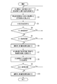
- FIG. 3 is a flowchart showing an example of control performed by the exhaust gas purification system shown in FIG.
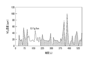
- FIG. 4 is a graph showing an example of a temporal change in the NO x concentration detected by a sensor included in the exhaust gas purification system shown in FIG.
- FIG. 5 is a graph showing another example of the temporal change in the NO x concentration detected by the sensor included in the exhaust gas purification system shown in FIG.
- FIG. 6 is a graph showing an example of the NO x emission amount per unit travel distance.
- FIG. 7 is a graph showing another example of the NO x emission amount per unit travel distance.
- FIG. 8 is a graph showing still another example of the NO x emission amount per unit travel distance.
- FIG. 9 is a graph showing still another example of the NO x emission amount per unit travel distance.
- FIG. 10 is a perspective view schematically showing that the exhaust gas purification system shown in FIG. 2 alerts the driver that the catalyst replacement time is approaching.
- FIG. 11 is a graph for explaining a method for estimating the cumulative travel distance at which the amount of nitrogen oxides discharged per unit travel distance by the automatic propulsion vehicle reaches the third set value based on the NO x emission amount. is there.
- the first to fourth setting values are stored in advance in the storage unit 820 shown in FIG. 2.
- the first set value is a threshold related to the concentration of NO x in the exhaust gas just prior to release to the atmosphere.
- the second set value is a threshold value regarding the NO x emission amount per unit travel distance.
- the first set value is 200 ppm and the second set value is a value larger than 0.11 g / km and smaller than 0.20 g / km.
- the third set value is a threshold value related to the NO x emission amount per unit travel distance, and is a value smaller than the second set value.
- the fourth set value is a threshold value regarding a difference ⁇ D1 between the accumulated travel distance D1 at which the NO x emission amount reaches the third set value and the actual accumulated travel distance D.
- the sensor 76b, the speedometer 90, and the air flow meter 60 are connected to the processing unit 810 illustrated in FIG.
- the sensor 76b detects the NO x concentration C1 in the exhaust gas.
- the speedometer 90 measures the traveling speed V1 of the automobile 1 shown in FIG.
- the air flow meter 60 detects the flow rate F1 of air flowing into the diesel engine 50.
- the processing unit 810 calculates the travel distance D at time t2 from the travel distance ⁇ D or travel speed V1 of the automobile 1 within the time interval ⁇ t and the past travel distance D0 stored in the storage unit 820. To do.
- the processing unit 810 calculates the NO x emission amount E1 and the travel distance D per unit travel distance from the signals corresponding to the NO x concentration C1, the travel speed, and the air flow rate F1 (step S2 in FIG. 3).
- the storage unit 820 stores the NO x emission amount E1 and the travel distance D (step S3 in FIG. 3).
- the NO x emission amount E1 per unit travel distance is calculated using, for example, the following equation.
- t1 and t2 represent time.
- the difference (time interval ⁇ t) between time t2 and time t1 is constant or is the time required to travel a certain distance.
- time t2 and time t1 is constant.
- M NOx is an average molecular weight of NO x and is a constant here.
- NO x is nitric oxide molecular weight of 30 (NO), and nitrogen dioxide molecular weight of 46 (NO 2), 1: included in a molar ratio of when a mixture, of the NO x
- the average molecular weight is 38.
- NO x concentration C1 is the volume concentration (vol / vol).
- the units of the NO x emission amount E1, the traveling speed V1, and the air flow rate F1 are “g / km”, “km / second”, and “g / second”, respectively.
- the processing unit 810 compares the NO x concentration C1 with the first set value (step S4 in FIG. 3). As shown in FIG. 4, when the NO x concentration C1 is less than the first set value or less than or equal to the first set value, the processing unit 810 uses the exhaust gas purification device 70a, in particular, the exhaust gas purification catalysts 712 and 722. In addition, for at least one of the diesel particulate filters 713, for example, it is determined that the performance is maintained at a sufficient level for all of them. In this case, the control unit 80 repeats the sequence including steps S1 to S4 in FIG.
- the processing unit 810 compares the NO x emission amount E1 with the second set value (FIG. 5). 3 step S5). As shown in FIGS. 6 to 8, when the NO x emission amount E1 is less than the second set value or less than or equal to the second set value, the processing unit 810 uses the exhaust gas purification device 70a, particularly for exhaust gas purification. For at least one of the catalysts 712 and 722 and the diesel particulate filter 713, for example, it is determined that the performance thereof is maintained at a sufficient level for all of them. In this case, the control unit 80 repeats the sequence including step S1 in FIG. 3 and subsequent steps.
- the control unit 80 informs the display unit 100 of the image signal corresponding to the first warning information. Is output.
- the display unit 100 notifies the driver by displaying the first warning information as, for example, a character string as shown in FIG. 10 (step S6 in FIG. 3).
- the display unit 100 may display the first warning information in a form other than characters such as a mark.
- the processing unit 810 estimates the cumulative travel distance D1 at which the NO x emission amount E1 reaches the third set value (step S7 in FIG. 3).
- the processing unit 810 for each of two or more time intervals ⁇ t, the NO x concentration C1 detected by the sensor 76b during this time interval ⁇ t, and the amount or flow rate of air supplied to the diesel engine 50 within the time interval ⁇ t. Nitrogen oxidation exhausted per unit travel distance from F1 or the amount or flow rate of exhaust gas discharged by the diesel engine 50 within this time interval ⁇ t and the travel distance or travel speed V1 of the vehicle 1 within this time interval ⁇ t Calculate the amount of objects.
- the cumulative travel distance D1 at which E1 reaches the third set value is estimated.
- processor 810, storage unit 820 has stored so far, from two or more data sets each including a NO x emission E1 and travel distance D, as shown in FIG. 11, NO x The relationship between the discharge amount E1 and the travel distance D is obtained. Then, the processing unit 810 estimates the cumulative travel distance D1 at which the NO x emission amount E1 reaches the third set value by extrapolation.
- the processing unit 810 calculates a difference ⁇ D1 between the estimated cumulative travel distance D1 and the actual cumulative travel distance D (step S8 in FIG. 3).
- the processing unit 810 compares the difference ⁇ D1 with the fourth set value (step S9 in FIG. 3). When the difference ⁇ D1 is greater than or equal to the fourth set value or exceeds the fourth set value, the control unit 80 repeats the sequence including step S1 in FIG. 3 and subsequent steps.
- the control unit 80 When the difference ⁇ D1 is less than the fourth set value or less than the fourth set value, the control unit 80 includes the components included in the exhaust gas purification device 70a, in particular, the exhaust gas purification catalysts 712 and 722 and the diesel particulates. It is determined that at least one of the filters 713 needs to be replaced or is about to be replaced. In this case, the control unit 80 outputs an image signal corresponding to the second warning information to the display unit 100. The display unit 100 notifies the driver by displaying the second warning information (step S10 in FIG. 3).
- first and second warning information may be the same or different.
- first warning information is displayed continuously and the second warning information is displayed blinking so that they can be distinguished.
- the concentration of NO x C1 and the air flow F1 and the running speed V1 Prefecture calculates the amount E1 of the NO x which car 1 is discharged per unit travel distance.
- the cumulative travel distance D1 at which the NO x emission amount E1 reaches the third set value is estimated, and the difference ⁇ D1 between the estimated cumulative travel distance D1 and the actual cumulative travel distance D is set to the fourth set value.
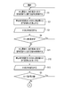
- FIG. 12 is a flowchart showing a part of another example of control performed by the exhaust gas purification system shown in FIG.
- FIG. 13 is a flowchart showing the remainder of the control shown in part in FIG.
- the control shown in FIGS. 12 and 13 is the same as the control described with reference to FIG. 3 except for the following points. That is, under the control shown in FIGS. 12 and 13, the control unit 80 executes steps S11 to S13 between step S4 and step S5, and steps S14 to S16 between step S6 and step S7. Execute. Steps S11 to S13 are the same as steps S1 to S3, respectively. Steps S14 to S16 are the same as steps S1 to S3, respectively.
- the processing unit 810 determines Yes in step S5
- the control unit 80 executes the sequence including steps S11 to S13 and S5 again.
- the control unit 80 executes the sequence including steps S14 to S16 and S7 to S9 again.
- step S5 when the result of the determination in steps S5 and S9 is Yes, the process returns to step S1.
- the process when the result of determination in steps S5 and S9 is Yes, the process returns to steps S11 and S14 without returning to step S1. That is, in the latter control, if the result of determination in step S4 is No, step S4 is not executed again, and if the result of determination in step S5 is No, step S5 is performed again. None executed. Even when such control is performed, the same effect as that obtained when the control described with reference to FIG. 3 is performed can be obtained.
- FIG. 14 is a flowchart showing a part of still another example of control performed by the exhaust gas purification system shown in FIG.
- FIG. 15 is a flowchart showing another part of the control partially shown in FIG.
- FIGS. 14 and 15 The control shown in FIGS. 14 and 15 is the same as the control described with reference to FIGS. 12 and 13 except that the steps shown in FIGS. 14 and 15 are executed instead of the steps shown in FIG. .
- control unit 80 first executes steps S17 to S19 after step S10. Steps S17 to S19 are the same as steps S1 to S3 described above, respectively.
- Step S20 is the same as step S7, except that the fifth set value is used instead of the third set value and the cumulative travel distance D2 is estimated instead of the cumulative travel distance D1.
- the fifth set value may be equal to or different from the third set value. In the latter case, the fifth set value may be smaller or larger than the third set value.
- it is assumed that the fifth set value is equal to the third set value.
- Step S22 is the same as step S9 except that the difference ⁇ 2 and the sixth set value are used instead of the difference ⁇ D1 and the fourth set value, respectively.
- the sixth set value is smaller than the fourth set value.
- the fourth setting value is 20000 km and the sixth setting value is 10000 km.
- step S22 the control unit 80 executes the sequence including steps S17 to S22 again.
- the control unit 80 outputs an image signal corresponding to the third warning information to the display unit 100.
- the display unit 100 notifies the driver by displaying the third warning information (step S23 in FIG. 15).
- Steps S24 to S26 are the same as steps S1 to S3 described above, respectively.
- Step S27 is the same as step S5 except that the seventh setting value is used instead of the second setting value.
- the seventh set value is larger than the second set value.
- step S27 the control unit 80 executes the sequence including steps S24 to S27 again.
- the control unit 80 outputs an image signal corresponding to the fourth warning information to the display unit 100.
- the display unit 100 notifies the driver by displaying the fourth warning information (step S28 in FIG. 15).
- the fourth warning information is information indicating that at least one of the exhaust gas purification catalysts 712 and 722 and the diesel particulate filter 713 should be replaced, for example.
- the combustion engine is a diesel engine has been described above as an example, but the combustion engine may be another internal combustion engine such as a gasoline engine or an external combustion engine.
- the output of the combustion engine is used as a propulsive force, but the output of the combustion engine is used for power generation, and the output of another device that is driven by the electric power generated thereby, for example, the output of the electric motor. It may be used as a driving force.
- an automatic propulsion vehicle is a vehicle other than a four-wheeled vehicle, such as a two-wheeled vehicle, a multi-wheeled vehicle of five or more wheels, a mobile heavy machine, a railway It may be a vehicle, a ship, or an airplane.
Landscapes
- Engineering & Computer Science (AREA)
- Chemical & Material Sciences (AREA)
- Chemical Kinetics & Catalysis (AREA)
- Combustion & Propulsion (AREA)
- General Engineering & Computer Science (AREA)
- Mechanical Engineering (AREA)
- Health & Medical Sciences (AREA)
- General Chemical & Material Sciences (AREA)
- Oil, Petroleum & Natural Gas (AREA)
- Analytical Chemistry (AREA)
- Environmental & Geological Engineering (AREA)
- Biomedical Technology (AREA)
- Toxicology (AREA)
- Exhaust Gas After Treatment (AREA)
- Exhaust Gas Treatment By Means Of Catalyst (AREA)
Abstract
基準値を超える量のNOxが実走行で排出される可能性が低い排ガス浄化技術を提供する。本発明の排ガス浄化システムは、自動推進車両に搭載された燃焼機関(50)が排出する排ガスを浄化するものであって、1以上の排ガス浄化用触媒(712、713及び722)を含み、燃焼機関(50)から排ガスが供給され、排ガスを大気へ放出可能に浄化する排ガス浄化装置(70a)と、浄化された排ガスに含まれる窒素酸化物の濃度を検知するセンサ(76b)と、センサ(76b)が検知した濃度に基づいて、排ガス浄化用触媒(712、713及び722)の少なくとも1つについて、その性能が十分なレベルを維持しているかを判断する処理部(810)とを備えている。
Description
本発明は、排ガス浄化システム及び自動推進車両に関する。
ディーゼル機関などの燃焼機関を搭載した自動推進車両は、燃焼機関が排出した排ガスを、1以上の排ガス浄化用触媒によって大気へ放出可能に浄化している。それ故、排ガス浄化用触媒の性能が劣化すると、大気へと放出される排ガスにおける有害成分の濃度、例えば、窒素酸化物(NOx)の濃度が上昇する。
特開2000-18023号公報には、NOx吸蔵触媒の劣化度を判定する診断装置が記載されている。この診断装置では、或るリッチスパイクと次のリッチスパイクとの間の期間内で、NOx吸蔵触媒の出口部でのNOx濃度が最低値となったときにおける、NOx吸蔵触媒の出口部でのNOx濃度とNOx吸蔵触媒の入口部でのNOx濃度との比に基づいて、NOx吸蔵触媒の劣化度を判定する。
特開2012-36856号公報には、ディーゼル酸化触媒と、その下流側に設置され、NOxを窒素へと還元する選択還元触媒とを含んだ排ガス浄化システムについて、ディーゼル酸化触媒の劣化度を判定するための診断装置が記載されている。この診断装置は、ディーゼル酸化触媒の上流側における排ガス中のNOx量に対する選択還元触媒の下流側に設置されたNOxセンサが出力する検出値の比と、選択還元触媒の下流側における排ガス中のNO2比率との関係を記憶したセンサ特性記憶手段を含んでいる。
ここで、ディーゼル酸化触媒の上流側における排ガス中のNOx量は、ディーゼル酸化触媒の上流側における排ガス中のNOx濃度と、給気又は排気流量とから算出される値である。また、ディーゼル酸化触媒の上流側における排ガス中のNOx濃度は、ディーゼル機関の運転状態、例えば、アクセル開度及び回転数と、ディーゼル酸化触媒の上流側における排ガス中のNOx濃度との関係を記述したマップに、ディーゼル機関の運転状態を参照することによって得られる値である。そして、上記のNO2比率は、選択還元触媒の下流側における排ガス中のNOx量に対する選択還元触媒の下流側における排ガス中の二酸化窒素(NO2)量の比である。
特開2012-36856号公報に記載された診断装置は、ディーゼル機関の運転状態と給気又は排気流量とからディーゼル酸化触媒の上流側における排ガス中のNOx量を算出し、このNOx量に対する、NOxセンサが出力する検出値の比を、センサ特性記憶手段が記憶している関係に参照して、選択還元触媒の下流側における排ガス中のNO2比率を演算する。そして、このNO2比率に基づいて、ディーゼル酸化触媒の劣化度を判定する。
特開2012-219740号公報には、空燃比を燃料リーンから燃料リッチへ切り替え、触媒を通過した排ガスについて、時間の経過に応じたNOx濃度の低下をNOx浄化速度として求め、このNOx浄化速度に基づいて触媒の排ガス浄化性能を評価することが記載されている。
NOx排出に対する規制は、今後、益々厳しくなり、実走行でのNOx排出量も規制対象になる。本発明者らは、上述した技術では、基準値を超える量のNOxが実走行で排出される可能性があると考えている。
そこで、本発明は、基準値を超える量のNOxが実走行で排出される可能性が低い排ガス浄化技術を提供することを目的とする。
本発明の第1側面によると、自動推進車両に搭載された燃焼機関が排出する排ガスを浄化する排ガス浄化システムであって、1以上の排ガス浄化用触媒を含み、前記燃焼機関から前記排ガスが供給され、前記排ガスを大気へ放出可能に浄化する排ガス浄化装置と、前記排ガス浄化装置によって浄化された前記排ガスに含まれる窒素酸化物の濃度を検知するセンサと、前記センサが検知した前記濃度に基づいて、前記1以上の排ガス浄化用触媒の少なくとも1つについて、その性能が十分なレベルを維持しているかを判断する処理部とを備えた排ガス浄化システムが提供される。
本発明の第2側面によると、前記処理部は、前記センサが検知した前記濃度が第1設定値未満であるか又は前記第1設定値以下である場合に、前記1以上の排ガス浄化用触媒の前記少なくとも1つについて、その性能が十分なレベルを維持していると判断する第1側面に係る排ガス浄化システムが提供される。
本発明の第3側面によると、前記処理部は、或る時間間隔内に前記センサが検知した前記濃度と、前記時間間隔内に前記燃焼機関へ供給した空気の量若しくは流量又は前記時間間隔内に前記燃焼機関が排出した前記排ガスの量若しくは流量と、前記時間間隔内における前記自動推進車両の走行距離又は走行速度とから、前記自動推進車両が単位走行距離当たりに排出した窒素酸化物の量を算出し、この量が第2設定値未満であるか又は前記第2設定値以下であるときに、前記1以上の排ガス浄化用触媒の前記少なくとも1つについて、その性能が十分なレベルを維持していると判断する第1又は第2側面に係る排ガス浄化システムが提供される。
本発明の第4側面によると、前記処理部は、2以上の時間間隔の各々について、前記時間間隔内に前記センサが検知した前記濃度と、前記時間間隔内に前記燃焼機関へ供給した空気の量若しくは流量又は前記時間間隔内に前記燃焼機関が排出した前記排ガスの量若しくは流量と、前記時間間隔内における前記自動推進車両の走行距離又は走行速度とから、前記自動推進車両が単位走行距離当たりに排出した窒素酸化物の量を算出し、前記自動推進車両の累積走行距離に対する、前記自動推進車両が単位走行距離当たりに排出した窒素酸化物の量の変化から、前記自動推進車両が単位走行距離当たりに排出する窒素酸化物の量が第3設定値に到達する累積走行距離を推定する第1乃至第3側面の何れかに係る排ガス浄化システムが提供される。
本発明の第5側面によると、前記処理部は、推定した前記累積走行距離と実際の累積走行距離との差が第4設定値未満であるか又は前記第4設定値以下である場合に、前記1以上の排ガス浄化用触媒の前記少なくとも1つについて、その交換が必要であるか又はその交換時期が近付いていると判断する第4側面に係る排ガス浄化システムが提供される。
本発明の第6側面によると、前記処理部における処理の結果を出力する出力部を更に備えた第1乃至第5側面の何れかに係る排ガス浄化システムが提供される。
本発明の第7側面によると、前記燃焼機関はディーゼル機関であり、前記1以上の排ガス浄化用触媒は、吸蔵還元触媒、尿素選択還元触媒及び炭化水素選択還元触媒の少なくとも1つを含んだ第1乃至第6側面の何れかに係る排ガス浄化システムが提供される。
本発明の第8側面によると、第1乃至第7側面の何れかに係る排ガス浄化システムを備えた自動推進車両が提供される。
以下に、本発明の実施形態について、図面を参照しながら説明する。なお、同様又は類似した機能を有する要素については、同一の参照符号を付し、重複する説明は省略する。
図1は、本発明の一実施形態に係る自動推進車両を概略的に示す側面図である。図2は、図1に示す自動推進車両に搭載可能な排ガス浄化システムの一例を概略的に示す図である。
図1には、自動推進車両の一例として、四輪自動車(以下、自動車という)1を描いている。なお、図1及び図2では、理解を容易にするために、一部の構成要素を省略している。また、以下の説明において、用語「前」及び「後」は、自動車1の進行方向を基準として使用することとし、用語「上流」及び「下流」は、排ガスの流れを基準として使用することとする。
図1に示す自動車1は、図2に示すディーゼル機関50を乗員室の前方に搭載した四輪駆動車である。
図1に示す自動車1は、車両本体を含んでいる。車両本体は、図示しないフレームと車体10とを含んでいる。フレーム及び車体10は、一体化されていてもよい。即ち、車両本体には、モノコック構造を採用してもよい。
フレームには、駆動装置、足回り装置、加速装置、ブレーキ装置及びステアリング装置などが搭載されている。
駆動装置は、燃焼機関、給気装置、排気装置、燃料供給装置及び動力伝導装置などを含んでいる。
燃焼機関は、上記の通り、図2に示すディーゼル機関50である。図2には、ディーゼル機関50の構成要素として、シリンダ51、ピストンヘッド52、連接棒53、吸入バルブ54、排気バルブ55、及び燃料噴射ノズル56のみを描いている。ディーゼル機関50は、ここでは、4ストロークサイクルディーゼル機関である。ディーゼル機関50は、2ストロークサイクルディーゼル機関であってもよい。
給気装置は、エアフィルタと給気管とエアフローメータ60とを含んでいる。給気装置は、車両の外部から空気を取り入れ、これを、エアフィルタによって塵などを除去した後に、給気管を介してディーゼル機関50の燃焼室へと供給する。エアフローメータ60は、給気管を流れる空気の流量を検知する。なお、給気装置は、圧力が高められた空気を燃焼室へと供給可能とする過給機を更に含んでいてもよい。
排気装置は、図2に示す排気装置70である。排気装置70は、ディーゼル機関50における燃料、ここでは軽油の燃焼によって生じた排ガスを浄化するとともに、排気音を低減する役割を果たす。
排気装置70は、触媒コンバータ71及び72と、マフラー73と、マフラーカッタ74と、パイプ75a、75b、75c及び75dと、センサ76a及び76bとを含んでいる。触媒コンバータ71及び72並びにパイプ75bは、排ガスを大気へ放出可能に浄化する排ガス浄化装置70aを構成している。マフラー73、パイプ75d及びマフラーカッタ74は、消音装置70bを構成している。
触媒コンバータ71は、コンバータボディ711と、排ガス浄化用触媒712と、ディーゼルパーティキュレートフィルタ(Diesel Particulate Filter; DPF)713とを含んでいる。
コンバータボディ711は、例えば、金属又は合金からなる。コンバータボディ711は、吸気口と排気口とが設けられた中空構造を有している。コンバータボディ711の吸気口は、パイプ75aと排気マニホルド(図示せず)とを介して、ディーゼル機関50のピストン室に接続されている。コンバータボディ711の排気口には、パイプ75bの一端が接続されている。
排ガス浄化用触媒712は、ストレートフロータイプのモノリス触媒である。排ガス浄化用触媒712は、コンバータボディ711の吸気口に供給された排ガスが、排ガス浄化用触媒712の貫通孔を通過し、その後、ディーゼルパーティキュレートフィルタ713へと供給されるように、コンバータボディ711内に収容されている。
一例によれば、排ガス浄化用触媒712は、ディーゼル酸化触媒(Diesel Oxidation Catalyst; DOC)である。他の例によれば、排ガス浄化用触媒712は、NOx吸蔵還元(NOx storage and reduction; NSR)触媒である。
排ガス浄化用触媒712は、モノリスハニカム基材と、その隔壁上に設けられた触媒層とを含んでいる。
モノリスハニカム基材は、例えば、一方の底面から他方の底面へと各々が延びた複数の貫通孔が設けられた柱体である。モノリスハニカム基材は、例えば、コージェライト及び炭化珪素などのセラミックスからなる。
触媒層は、モノリスハニカム基材の隔壁上に設けられている。触媒層は、単層構造を有していてもよく、多層構造を有していてもよい。
排ガス浄化用触媒712がディーゼル酸化触媒である場合、触媒層は、例えば、第1担体と第1貴金属元素とを含んでいる。
第1担体は、アルミナなどの耐熱性材料からなる粒子である。第1担体は、第1貴金属元素を担持している。第1担体は、第1貴金属の表面積を増大させると共に、触媒反応による発熱を消散させて第1貴金属のシンタリングを抑制する役割を担っている。
第1貴金属元素は、例えば、白金及びパラジウムなどの白金族元素である。触媒層は、第1貴金属元素として、単一の貴金属元素を含んでいてもよく、複数の貴金属元素を含んでいてもよい。
第1貴金属元素は、排ガス中の一酸化炭素(CO)及び炭化水素(HC)の酸化を促進する。第1貴金属元素の作用により、排ガス中の一酸化炭素及び炭化水素の濃度が低下し、高沸点の炭化水素や硫化物からなる粒子状物質(particulate matter;PM)の一部が排ガスから除去される。
排ガス浄化用触媒712がNOx吸蔵還元触媒である場合、触媒層は、例えば、第2担体と第2貴金属元素とNOx吸蔵材とを含んでいる。
第2担体は、アルミナなどの耐熱性材料からなる粒子である。第2担体は、第2貴金属元素と、任意にNOx吸蔵材とを担持している。第2担体は、第2貴金属の表面積を増大させると共に、触媒反応による発熱を消散させて第2貴金属のシンタリングを抑制する役割を担っている。
第2貴金属元素は、例えば、白金、パラジウム及びロジウムなどの白金族元素である。第2貴金属元素は、排ガス中のNOxの還元反応を促進する。第2貴金属元素の作用により、排ガス中のNOx濃度が低下する。
NOx吸蔵材は、例えば、バリウム、カリウム、リチウム及びセリウムの少なくとも1つを含み、炭酸塩若しくは酸化物の形態にある化合物又はそれらの組み合わせである。NOx吸蔵材は、酸化性雰囲気下においてNOxを吸蔵し、還元性雰囲気下においてNOxを放出する。
ディーゼルパーティキュレートフィルタ713は、ウォールフロータイプのモノリス触媒である。ディーゼルパーティキュレートフィルタ713は、排ガス浄化用触媒712の貫通孔を通過した排ガスが、ディーゼルパーティキュレートフィルタ713の隔壁を透過し、その後、コンバータボディ711の排気口から触媒コンバータ71の外部へと排出されるように、コンバータボディ711内に収容されている。ディーゼルパーティキュレートフィルタ713は、排ガスから粒子状物質を除去する。
ディーゼルパーティキュレートフィルタ713は、フィルタ基材を含んでいる。フィルタ基材は、例えば、ハニカム構造体と栓とを含んでいる。
ハニカム構造体は、例えば、一方の底面から他方の底面へと各々が延びた複数の貫通孔が設けられた柱体である。ハニカム構造体は、貫通孔の側壁を構成している、即ち、隣り合った貫通孔を仕切っている多孔質隔壁を含んでいる。これら多孔質隔壁は、排ガスが同伴している粒子状物質を殆ど透過させることなしに、排ガスを透過させる。
ハニカム構造体の材料としては、例えば、コージェライト及び炭化珪素などのセラミックスを使用することができる。ハニカム構造体には、金属製の不織布が編み込まれていてもよい。
栓の一部は、ハニカム構造体の孔の一部を下流側で塞いでいる。孔を下流側で塞いでいる栓と、この孔の側壁を構成している多孔質隔壁とは、上流側で開口した上流セルを形成している。
栓の残りは、ハニカム構造体の残りの孔を上流側で塞いでいる。孔を上流側で塞いでいる栓と、この孔の側壁を構成している多孔質隔壁とは、下流側で開口した下流セルを形成している。
これら栓は、下流側が栓で塞がれている孔と上流側が栓で塞がれている孔とが多孔質隔壁を挟んで隣り合うように配置されている。即ち、上流セルと下流セルとは、多孔質隔壁を挟んで隣り合っている。
栓の材料としては、例えば、コージェライト及び炭化珪素などのセラミックスを使用することができる。
排ガス浄化用触媒712の貫通孔を通過した排ガスは、先ず、ディーゼルパーティキュレートフィルタ713の上流セルに流入する。次いで、この排ガスは、上流セルと下流セルとを仕切っている多孔質隔壁を透過して、下流セルへ流入する。この際に、排ガスから粒子状物質が除去される。
ディーゼルパーティキュレートフィルタ713は、フィルタとしての機能に加え、他の機能を更に有していてもよい。即ち、ディーゼルパーティキュレートフィルタ713は、ハニカム構造体及び/又は栓上に設けられた触媒層を更に含んでいてもよい。
例えば、ディーゼルパーティキュレートフィルタ713は、フィルタとしての機能に加え、選択還元(Selective Catalytic Reduction; SCR)触媒としての機能、例えば、炭化水素又はアンモニアとの反応によるNOxの窒素への還元を促進する機能を更に有していてもよい。即ち、ディーゼルパーティキュレートフィルタ713は、尿素選択還元触媒又は炭化水素選択還元触媒としての機能を更に有していてもよい。
ディーゼルパーティキュレートフィルタ713に尿素選択還元触媒としての機能を付与する場合、その触媒層の活性成分としては、例えば、ナトリウム及びカリウムなどのアルカリ金属元素のイオンが鉄及び銅などの遷移金属元素のイオンで部分的に交換されたゼオライトを使用することができる。或いは、この活性成分として、タングステン及びバナジウムなどの卑金属の酸化物を使用することもできる。
なお、ディーゼルパーティキュレートフィルタ713に尿素選択還元触媒としての機能を付与する場合、排気装置70には、例えば、ディーゼルパーティキュレートフィルタ713の上流で排ガスに尿素水溶液を注入する第1インジェクタを更に設ける。
上記の通り、パイプ75bの一端は、コンバータボディ711の排気口に接続されている。パイプ75bには、センサ76aが設置されている。センサ76aは、触媒コンバータ71が排出した排ガスにおけるNOx濃度を検知する。センサ76aの出力は、例えば、排ガスへのアンモニア又はその前駆体、例えば尿素水溶液の注入量の制御に利用する。
触媒コンバータ72は、コンバータボディ721と、排ガス浄化用触媒722とを含んでいる。
コンバータボディ721は、例えば、金属又は合金からなる。コンバータボディ721は、吸気口と排気口とが設けられた中空構造を有している。コンバータボディ711の吸気口は、パイプ75bを介して、コンバータボディ711の排気口に接続されている。コンバータボディ721の排気口には、パイプ75cの一端が接続されている。
排ガス浄化用触媒722は、ストレートフロータイプのモノリス触媒である。排ガス浄化用触媒722は、コンバータボディ721の吸気口に供給された排ガスが、排ガス浄化用触媒722の貫通孔を通過し、その後、コンバータボディ721の排気口から触媒コンバータ72の外部へと排出されるように、コンバータボディ721内に収容されている。
一例によれば、排ガス浄化用触媒722は、選択還元触媒としての機能と、アンモニアスリップ触媒(Ammonia Slip Catalyst; ASC)としての機能とを有している。
排ガス浄化用触媒722は、モノリスハニカム基材と、その隔壁上に設けられた触媒層とを含んでいる。
モノリスハニカム基材は、例えば、一方の底面から他方の底面へと各々が延びた複数の貫通孔が設けられた柱体である。モノリスハニカム基材は、例えば、コージェライト及び炭化珪素などのセラミックスからなる。
触媒層は、モノリスハニカム基材の隔壁上に設けられている。触媒層は、単層構造を有していてもよく、多層構造を有していてもよい。
排ガス浄化用触媒712が選択還元触媒としての機能とアンモニアスリップ触媒としての機能とを有している場合、触媒層には、例えば、基材のうち上流側部分の隔壁上に位置し、選択還元触媒としての機能を有している第1層と、基材のうち下流側部分の隔壁上に位置し、アンモニアスリップ触媒としての機能を有している第2層とを含んだ構造を採用してもよい。或いは、この場合、触媒層には、選択還元触媒としての機能を有している第1層と、第1層と基材の隔壁との間に介在し、アンモニアスリップ触媒としての機能とを有している第2層とを含んだ多層構造を採用してもよい。
選択還元触媒としての機能を有している第1層の活性成分としては、例えば、ナトリウム及びカリウムなどのアルカリ金属元素のイオンが鉄及び銅などの遷移金属元素のイオンで部分的に交換されたゼオライトを使用することができる。或いは、この活性成分として、タングステン及びバナジウムなどの卑金属の酸化物を使用することもできる。
アンモニアスリップ触媒は、酸化触媒であって、未反応のアンモニアの酸化を促進する。アンモニアの酸化によって窒素酸化物を生じるが、未反応のアンモニアの量は少ないので、アンモニアスリップ触媒において生成する窒素酸化物の量も少ない。即ち、アンモニアスリップ触媒は、排ガス中の窒素酸化物の濃度を大幅に上昇させることなく、排ガス中のアンモニアの濃度を低下させる。
アンモニアスリップ触媒としての機能を有している第2層は、例えば、第3担体と第3貴金属元素とを含んでいる。
第3担体は、アルミナなどの耐熱性材料からなる粒子である。第3担体は、第3貴金属元素を担持している。第3担体は、第3貴金属の表面積を増大させると共に、触媒反応による発熱を消散させて第3貴金属のシンタリングを抑制する役割を担っている。
第3貴金属元素は、例えば、白金及びパラジウムなどの白金族元素である。第3貴金属元素は、アンモニアの酸化を促進する。第2層は、第3貴金属元素として、単一の貴金属元素を含んでいてもよく、複数の貴金属元素を含んでいてもよい。例えば、第2層は、第2貴金属元素として、白金のみを含んでいてもよく、白金とパラジウムとを含んでいてもよい。
なお、排ガス浄化用触媒722が選択還元触媒としての機能とアンモニアスリップ触媒としての機能とを有している場合であって、ディーゼルパーティキュレートフィルタ713に選択還元触媒としての機能を付与しないときには、排気装置70には、例えば、第1インジェクタは設けずに、ディーゼルパーティキュレートフィルタ713と排ガス浄化用触媒722との間で、排ガスに、アンモニア又はその前駆体、例えば尿素水溶液を注入する第2インジェクタのみを設ける。
また、ディーゼルパーティキュレートフィルタ713に選択還元触媒としての機能を付与する場合、例えば、上記の第1インジェクタが排ガスに注入したアンモニア又はその前駆体の一部は、触媒コンバータ71において全てが消費されず、触媒コンバータ72へ供給される可能性がある。それ故、排ガス浄化用触媒722が選択還元触媒としての機能とアンモニアスリップ触媒としての機能とを有している場合であって、ディーゼルパーティキュレートフィルタ713に選択還元触媒としての機能を付与するときには、排気装置70には、上記の第2インジェクタを設けてもよく、設けなくてもよい。
上記の通り、パイプ75cの一端は、コンバータボディ721の排気口に接続されている。パイプ75cには、センサ76bが設置されている。センサ76bは、触媒コンバータ72が排出した排ガスにおけるNOx濃度を検知する。センサ76bの出力は、例えば、排ガス浄化装置70aが含んでいる排ガス浄化用触媒の少なくとも1つについて、その性能が十分なレベルを維持しているかを判断するのに利用する。また、センサ76bの出力は、排ガスへのアンモニア又はその前駆体、例えば尿素水溶液の注入量の制御にも利用することができる。
マフラー73は、例えば、金属又は合金からなる。マフラー73は、吸気口と排気口とが設けられ、内部が複数の室に仕切られた中空構造を有している。マフラー73は、排気音を低減する役割を果たす。マフラー73の吸気口は、パイプ75cを介して、コンバータボディの排気口に接続されている。マフラー73の排気口には、パイプ75dの一端が接続されている。
マフラーカッタ74は、例えば、金属又は合金からなる。マフラーカッタ74は、吸気口と排気口とが設けられた中空構造を有している。マフラーカッタ74の吸気口は、パイプ75dの他端に接続されている。マフラーカッタ74は省略することができる。
燃料供給装置は、燃料タンクと燃料噴射ポンプと燃料管とを含んでいる。燃料供給装置は、燃料噴射ポンプを動作させることにより、燃料タンクに収容されている軽油を、燃料管を介して燃料噴射ノズル56へと送る。図1に示す自動車1は、燃料噴射ポンプの動作を制御することにより、図2に示すディーゼル機関50の出力を調整する。
動力伝導装置は、変速機と駆動軸と差動装置と車軸とを含んでいる。動力伝達装置は、例えば、ディーゼル機関50の回転運動を、変速機、駆動軸及び差動装置を介して車軸へと伝達する。
足回り装置は、懸架装置と、車輪と、図1に示すタイヤ20とを含んでいる。懸架装置は、フレームに固定されており、前輪用及び後輪用の車軸を回転可能に支持している。車輪は、車軸に接続されており、タイヤ20をそれらの内側から支持している。
加速装置は、アクセルペダルを含んでいる。加速装置は、例えば、アクセルペダルの変位に応じて、図2に示す燃料噴射ノズル56が噴射する軽油の量を変化させる。
ブレーキ装置は、ブレーキペダルとブレーキ本体とを含んでいる。ブレーキ本体は、例えば、懸架装置に取り付けられたブレーキキャリパと車軸に取り付けられたブレーキディスクとを含んだディスクブレーキである。ブレーキ装置は、例えば、ブレーキペダルの変位に応じてブレーキ本体の制動力を変化させる。
ステアリング装置は、ステアリングホイールとステアリングアームとステアリングギアとピットマンアームとタイロッドとを含んでいる。ステアリング装置は、ステアリングの回転角に応じて前輪の向きを変化させる。
車両本体は、図2に示す制御部80を更に含んでいる。制御部80は、センサ76bが検知した排ガス中のNOx濃度に基づいて、排ガス浄化用触媒の少なくとも1つについて、その性能が十分なレベルを維持しているかを判断する。
制御部80は、処理部810と記憶部820とを含んでいる。制御部80は、排ガス浄化装置70aとともに、排ガス浄化システムを構成している。
処理部810は、中央処理装置(CPU)を含んでいる。
処理部810には、センサ76a及び76bと、上述したインジェクタとが接続されている。処理部810は、センサ76a及び76bが検知した排ガス中のNOx濃度に基づいて、インジェクタの動作を制御する。
処理部810には、センサ76a及び76bと、上述したインジェクタとが接続されている。処理部810は、センサ76a及び76bが検知した排ガス中のNOx濃度に基づいて、インジェクタの動作を制御する。
処理部810には、エアフローメータ60と、記憶部820と、後述する速度計90及び表示部100とが更に接続されている。処理部810には、速度計90を接続する代わりに、距離計を接続してもよい。或いは、処理部810には、速度計90又は距離計と接続されたセンサを接続してもよい。
処理部810は、センサ76b、エアフローメータ60及び速度計90の出力に基づいて、排ガス浄化用触媒の少なくとも1つについて、その性能が十分なレベルを維持しているかを判断する。そして、処理部810は、この判断の結果を表示部100へ出力する。なお、処理部810の動作については、後で詳しく説明する。
記憶部820は、処理部810に接続されている。記憶部820は、処理部810が読み込むプログラムや、処理部810から供給されたデータを記憶する不揮発性メモリを含んでいる。
車両本体は、図1に示す座席30及びダッシュボード40を更に含んでいる。ダッシュボード40は、ディーゼル機関50及び給気装置などが配置された機関室と、座席30が配置された乗員室とを仕切っている。ダッシュボード40には、速度表示器や警告灯などが設置されている。
また、ダッシュボード40には、図2に示す表示部100が設置されている。表示部100は、排ガス浄化用触媒の性能について処理部810が判断した結果を出力する出力部の一例である。表示部100は、排ガス浄化用触媒の性能について処理部810が判断した結果を、例えば、運転者又は整備若しくは点検作業者が知覚可能に表示する。なお、表示部100は、ダッシュボード40以外の位置に設置してもよい。
表示部100は、例えば、直視型ディスプレイ、ヘッドアップディスプレイなどの投射型ディスプレイ、警告灯、又はそれらの組み合わせである。表示部100には、例えば、液晶ディスプレイ、有機エレクトロルミネッセンスディスプレイ、発光ダイオード、又はそれらの組み合わせを使用することができる。
表示部100は、省略することができる。
例えば、制御部80に有線又は無線による通信を可能とする通信部を設けた場合、スマートフォンなどのデバイスと制御部80との通信を通じて、排ガス浄化用触媒の性能について処理部810が判断した結果を先のデバイスに表示させてもよい。この場合、通信部が上記の出力部に相当する。
例えば、制御部80に有線又は無線による通信を可能とする通信部を設けた場合、スマートフォンなどのデバイスと制御部80との通信を通じて、排ガス浄化用触媒の性能について処理部810が判断した結果を先のデバイスに表示させてもよい。この場合、通信部が上記の出力部に相当する。
或いは、排ガス浄化用触媒の性能について処理部810が判断した結果を、表示によって運転者又は整備若しくは点検作業者へ通知する構成を採用する代わりに、ブザーなどの警告音及び音声案内などにより運転者又は整備若しくは点検作業者へ通知する構成を採用してもよい。この場合、ブザーや音声案内装置が、上述した出力部に相当する。
次に、図1に示す自動車1の動作、特には、図2に示す排ガス浄化システムが行う制御について、図1乃至図11を参照しながら説明する。
図3は、図2に示す排ガス浄化システムが行う制御の一例を示すフローチャートである。図4は、図2に示す排ガス浄化システムが含んでいるセンサが検知したNOx濃度の時間変化の一例を示すグラフである。図5は、図2に示す排ガス浄化システムが含んでいるセンサが検知したNOx濃度の時間変化の他の例を示すグラフである。図6は、単位走行距離当たりのNOx排出量の一例を示すグラフである。図7は、単位走行距離当たりのNOx排出量の他の例を示すグラフである。図8は、単位走行距離当たりのNOx排出量の更に他の例を示すグラフである。図9は、単位走行距離当たりのNOx排出量の更に他の例を示すグラフである。図10は、図2に示す排ガス浄化システムが、運転者に、触媒の交換時期が近付いていることを注意喚起している様子を概略的に示す斜視図である。図11は、NOx排出量に基づいて、自動推進車両が単位走行距離当たりに排出する窒素酸化物の量が第3設定値に到達する累積走行距離を推定する方法を説明するためのグラフである。
図1に示す自動車1の累積走行距離が増加すると、図2に示す排ガス浄化装置70aが含んでいる排ガス浄化用触媒の少なくとも1つの性能が変化する。排ガス浄化装置70aの性能が大幅に低下すると、規制値を超える量のNOxが放出される可能性がある。図3に示す制御を行うと、そのような可能性を低減することができる。
図3に示す制御では、図2に示す記憶部820に、第1乃至第4設定値を事前に記憶させておく。ここで、第1設定値は、大気へと放出する直前の排ガス中のNOx濃度に関する閾値である。第2設定値は、単位走行距離当たりのNOx排出量に関する閾値である。ここでは、一例として、第1設定値は200ppmであり、第2設定値は0.11g/kmより大きく且つ0.20g/kmよりも小さい値であるとする。また、第3設定値は、単位走行距離当たりのNOx排出量に関する閾値であって、第2設定値よりも小さな値である。そして、第4設定値は、NOx排出量が第3設定値に到達する累積走行距離D1と実際の累積走行距離Dとの差ΔD1に関する閾値である。
上記の通り、図2に示す処理部810には、センサ76b、速度計90及びエアフローメータ60が接続されている。センサ76bは、排ガス中のNOx濃度C1を検知する。速度計90は、図1に示す自動車1の走行速度V1を計測する。エアフローメータ60は、ディーゼル機関50への流入する空気の流量F1を検知する。図2に示す処理部810は、センサ76b、速度計90及びエアフローメータ60から、それぞれ、NOx濃度C1、走行速度V1及び空気流量F1に関する信号を取得する(図3のステップS1)。
処理部810は、時刻t1から時刻t2までの間に、即ち、時間間隔Δt(=t2-t1)内にセンサ76bが検知したNOx濃度C1と、この時間間隔Δt内にディーゼル機関50へ供給した空気の量若しくは流量F1又はこの時間間隔Δt内にディーゼル機関50が排出した排ガスの量若しくは流量と、この時間間隔Δt内における自動車1の走行距離ΔD又は走行速度V1とから、自動車1が単位走行距離当たりに排出したNOxの量E1を算出する。
また、処理部810は、上記の時間間隔Δt内における自動車1の走行距離ΔD又は走行速度V1と、記憶部820が記憶している過去の走行距離D0とから、時刻t2における走行距離Dを算出する。
例えば、処理部810は、NOx濃度C1、走行速度及び空気流量F1に対応した信号から、単位走行距離当たりのNOx排出量E1と走行距離Dとを算出する(図3のステップS2)。記憶部820は、これらNOx排出量E1及び走行距離Dを記憶する(図3のステップS3)。
単位走行距離当たりのNOx排出量E1は、例えば、以下の等式を用いて算出する。
単位走行距離当たりのNOx排出量E1は、例えば、以下の等式を用いて算出する。

ここで、「t1」及び「t2」は、時刻を表している。時刻t2と時刻t1との差(時間間隔Δt)は、一定であるか、又は、一定の距離を走行するのに要した時間である。ここでは、一例として、時刻t2と時刻t1との差は一定であるとする。
また、「MNOx」は、NOxの平均分子量であって、ここでは定数である。例えば、NOxが、分子量が30である一酸化窒素(NO)と、分子量が46である二酸化窒素(NO2)とを、1:1のモル比で含んだ混合物である場合、NOxの平均分子量は38である。
そして、上記等式において、NOx濃度C1は体積濃度(体積/体積)である。また、NOx排出量E1、走行速度V1及び空気流量F1の単位は、それぞれ、「g/km」、「km/秒」及び「g/秒」である。
次に、処理部810は、NOx濃度C1と第1設定値とを対比する(図3のステップS4)。図4に示すように、NOx濃度C1が第1設定値未満であったか又は第1設定値以下であった場合、処理部810は、排ガス浄化装置70a、特には、排ガス浄化用触媒712及び722並びにディーゼルパーティキュレートフィルタ713の少なくとも1つについて、例えば、それらの全てについて、その性能が十分なレベルを維持していると判断する。そして、この場合、制御部80は、図3のステップS1乃至S4を含むシーケンスを繰り返す。
図5に示すように、NOx濃度C1が第1設定値以上であったか又は第1設定値を超えた場合、処理部810は、NOx排出量E1と第2設定値とを対比する(図3のステップS5)。図6乃至図8に示すように、NOx排出量E1が第2設定値未満であったか又は第2設定値以下であった場合、処理部810は、排ガス浄化装置70a、特には、排ガス浄化用触媒712及び722並びにディーゼルパーティキュレートフィルタ713の少なくとも1つについて、例えば、それらの全てについて、その性能が十分なレベルを維持していると判断する。そして、この場合、制御部80は、図3のステップS1及びそれに続くステップを含むシーケンスを繰り返す。
図9に示すように、NOx排出量E1が第2設定値以上であったか又は第2設定値を超えた場合、制御部80は、表示部100に対し、第1警告情報に対応した画像信号を出力する。表示部100は、第1警告情報を、例えば、図10に示すように文字列で表示することにより、運転者に通知する(図3のステップS6)。なお、表示部100は、第1警告情報を、マークなどの文字以外の形態で表示してもよい。
次に、処理部810は、NOx排出量E1が第3設定値に到達する累積走行距離D1を推定する(図3のステップS7)。
例えば、処理部810は、2以上の時間間隔Δtの各々について、この時間間隔Δtにセンサ76bが検知したNOx濃度C1と、この時間間隔Δt内にディーゼル機関50へ供給した空気の量若しくは流量F1又はこの時間間隔Δt内にディーゼル機関50が排出した排ガスの量若しくは流量と、この時間間隔Δt内における自動車1の走行距離又は走行速度V1とから、自動車が単位走行距離当たりに排出した窒素酸化物の量を算出する。そして、処理部810は、自動車1の累積走行距離Dに対する、自動車1が単位走行距離当たりに排出した窒素酸化物の量E1の変化から、自動車1が単位走行距離当たりに排出するNOxの量E1が第3設定値に到達する累積走行距離D1を推定する。
一例によれば、処理部810は、記憶部820がこれまでに記憶した、NOx排出量E1と走行距離Dとを各々が含む2以上のデータセットから、図11に示すように、NOx排出量E1と走行距離Dとの関係を求める。そして、処理部810は、外挿法により、NOx排出量E1が第3設定値に到達する累積走行距離D1を推定する。
次に、処理部810は、推定した累積走行距離D1と実際の累積走行距離Dとの差ΔD1を算出する(図3のステップS8)。
次いで、処理部810は、差ΔD1と第4設定値とを対比する(図3のステップS9)。差ΔD1が第4設定値以上であったか又は第4設定値を超えた場合、制御部80は、図3のステップS1及びそれに続くステップを含むシーケンスを繰り返す。
差ΔD1が第4設定値未満であったか又は第4設定値以下であった場合、制御部80は、排ガス浄化装置70aが含んでいる部品、特には、排ガス浄化用触媒712及び722並びにディーゼルパーティキュレートフィルタ713の少なくとも1つについて、その交換が必要であるか又はその交換時期が近付いていると判断する。そして、この場合、制御部80は、表示部100に対し、第2警告情報に対応した画像信号を出力する。表示部100は、第2警告情報を表示することにより、運転者に通知する(図3のステップS10)。
なお、第1及び第2警告情報は、同一であっても、異なっていてもよい。第1及び第2警告情報が同一である場合、例えば、第1警告情報は連続表示し、第2警告情報は点滅表示することなどにより、それらを区別できるようにする。
上述した自動車1では、排ガスを大気へ放出可能に浄化する排ガス浄化装置70aによって浄化された排ガスに含まれるNOxの濃度C1をセンサ76bで検知する。即ち、最後尾の排ガス浄化用触媒を通過した排ガスに対して、NOx濃度C1の測定を行う。そして、このNOx濃度C1に基づいて、排ガス浄化用触媒712及び722並びにディーゼルパーティキュレートフィルタ713の少なくとも1つについて、その性能が十分なレベルを維持しているかを判断する。それ故、この自動車1は、基準値を超える量のNOxが実走行で排出される可能性が低い。
また、この自動車1では、NOx濃度C1と空気流量F1と走行速度V1とから、自動車1が単位走行距離当たりに排出したNOxの量E1を算出する。そして、この自動車1では、NOx排出量E1と第2設定値とを対比して、排ガス浄化用触媒712及び722並びにディーゼルパーティキュレートフィルタ713の少なくとも1つについて、その性能が十分なレベルを維持しているかを判断する。それ故、この自動車1は、基準値を超える量のNOxが実走行で排出される可能性が更に低い。
そして、この自動車1では、NOx排出量E1が第3設定値に到達する累積走行距離D1を推定し、推定した累積走行距離D1と実際の累積走行距離Dとの差ΔD1を第4設定値と対比して、排ガス浄化用触媒712及び722並びにディーゼルパーティキュレートフィルタ713の少なくとも1つについて、その交換が必要であるか又はその交換時期が近付いているか判断する。それ故、この自動車1は、基準値を超える量のNOxが実走行で排出される可能性が更に低い。
加えて、この自動車1では、NOx排出量E1と第2設定値との対比の結果、排ガス浄化用触媒712及び722並びにディーゼルパーティキュレートフィルタ713の少なくとも1つについて、その性能が十分なレベルを維持していると判断しなかった場合に、運転者等に第1警告情報を通知する。また、この自動車1では、差ΔD1を第4設定値との対比の結果、排ガス浄化用触媒712及び722並びにディーゼルパーティキュレートフィルタ713の少なくとも1つについて、その交換が必要であるか又はその交換時期が近付いていると判断した場合に、運転者等に第2警告情報を通知する。従って、運転者等は、排ガス浄化用触媒等の交換時期を事前に把握でき、それ故、交換時期を逸する可能性が低い。
図2に示す排ガス浄化システムでは、図3を参照しながら説明した制御を行う代わりに、以下の制御を行ってもよい。
図12は、図2に示す排ガス浄化システムが行う制御の他の例の一部を示すフローチャートである。図13は、図12に一部を示す制御の残りを示すフローチャートである。
図12及び図13に示す制御は、以下の点を除き、図3を参照しながら説明した制御と同様である。即ち、図12及び図13に示す制御のもとでは、制御部80は、ステップS4とステップS5との間でステップS11乃至S13を実行し、ステップS6とステップS7との間でステップS14乃至S16を実行する。ステップS11乃至S13は、それぞれ、ステップS1乃至S3と同様である。また、ステップS14乃至S16は、それぞれ、ステップS1乃至S3と同様である。そして、制御部80は、処理部810がステップS5においてYesと判断した場合、ステップS11乃至S13及びS5を含むシーケンスを再度実行する。また、制御部80は、処理部810がステップS9においてYesと判断した場合、ステップS14乃至S16及びS7乃至S9を含むシーケンスを再度実行する。
図3に示す制御では、ステップS5及びS9における判断の結果がYesであった場合、ステップS1へと戻る。これに対し、図12及び図13に示す制御では、ステップS5及びS9における判断の結果がYesであった場合、ステップS1へは戻らずに、それぞれ、ステップS11及びS14へ戻る。つまり、後者の制御では、ステップS4における判断の結果がNoであった場合、ステップS4が再度実行されることはなく、また、ステップS5における判断の結果がNoであった場合、ステップS5が再度実行されることはない。このような制御を行った場合も、図3を参照しながら説明した制御を行った場合と同様の効果が得られる。
図14は、図2に示す排ガス浄化システムが行う制御の更に他の例の一部を示すフローチャートである。図15は、図14に一部を示す制御の他の一部を示すフローチャートである。
図14及び図15に示す制御は、図13に示すステップの代わりに、図14及び図15に示すステップを実行すること以外は、図12及び図13を参照しながら説明した制御と同様である。
即ち、図14及び図15に示す制御では、制御部80は、ステップS10の後に、先ず、ステップS17乃至S19を実行する。ステップS17乃至S19は、それぞれ、上述したステップS1乃至S3と同様である。
次に、制御部80は、ステップS20乃至S22を実行する。
ステップS20は、第3設定値の代わりに第5設定値を用いて、累積走行距離D1の代わりに累積走行距離D2を推定すること以外は、ステップS7と同様である。第5設定値は、第3設定値と等しくてもよく、異なっていてもよい。後者の場合、第5設定値は、第3設定値よりも小さくてもよく、大きくてもよい。ここでは、一例として、第5設定値は第3設定値と等しいとする。
ステップS20は、第3設定値の代わりに第5設定値を用いて、累積走行距離D1の代わりに累積走行距離D2を推定すること以外は、ステップS7と同様である。第5設定値は、第3設定値と等しくてもよく、異なっていてもよい。後者の場合、第5設定値は、第3設定値よりも小さくてもよく、大きくてもよい。ここでは、一例として、第5設定値は第3設定値と等しいとする。
ステップS21は、累積走行距離D1の代わりに累積走行距離D2を用いて、差ΔD1の代わりに差ΔD2(=D2-D)を算出すること以外は、ステップS8と同様である。
ステップS22は、差ΔD1及び第4設定値の代わりに差Δ2及び第6設定値をそれぞれ用いること以外は、ステップS9と同様である。第6設定値は、第4設定値よりも小さな値である。ここでは、一例として、第4設定値は20000kmであり、第6設定値は10000kmであるとする。
制御部80は、処理部810がステップS22においてYesと判断した場合、ステップS17乃至S22を含むシーケンスを再度実行する。また、制御部80は、処理部810がステップS22においてNoと判断した場合、表示部100に対し、第3警告情報に対応した画像信号を出力する。表示部100は、第3警告情報を表示することにより、運転者に通知する(図15のステップS23)。
次に、制御部80は、ステップS24乃至S26を実行する。ステップS24乃至S26は、それぞれ、上述したステップS1乃至S3と同様である。
次いで、制御部80は、ステップS27を実行する。ステップS27は、第2設定値の代わりに第7設定値を用いること以外は、ステップS5と同様である。第7設定値は、第2設定値よりも大きな値である。
制御部80は、処理部810がステップS27においてYesと判断した場合、ステップS24乃至S27を含むシーケンスを再度実行する。また、制御部80は、処理部810がステップS27においてNoと判断した場合、表示部100に対し、第4警告情報に対応した画像信号を出力する。表示部100は、第4警告情報を表示することにより、運転者に通知する(図15のステップS28)。第4警告情報は、例えば、排ガス浄化用触媒712及び722並びにディーゼルパーティキュレートフィルタ713の少なくとも1つを交換すべきことを表す情報である。
この制御によれば、図3を参照しながら説明した制御や、図12及び図13を参照しながら説明した制御と比較して、表示部100により多くの警告画像を表示させる。従って、自動車1において、上記の制御を行うと、基準値を超える量のNOxが実走行で排出される可能性が更に低くなるのに加え、排ガス浄化用触媒等の交換時期を逸する可能性が更に低くなる。
以上、燃焼機関がディーゼル機関である場合を例に説明したが、燃焼機関は、ガソリン機関などの他の内燃機関であってもよく、外燃機関であってもよい。また、上記の例では、燃焼機関の出力を推進力として利用しているが、燃焼機関の出力を発電に利用し、これによって生じた電力で駆動する他の装置の出力、例えば電動機の出力を推進力として利用してもよい。
また、上記の説明では、自動推進車両として四輪自動車を例示しているが、自動推進車両は、四輪自動車以外の車両、例えば、二輪自動車、五輪以上の多輪自動車、移動式重機、鉄道車両、船、又は飛行機であってもよい。
Claims (8)
- 自動推進車両に搭載された燃焼機関が排出する排ガスを浄化する排ガス浄化システムであって、
1以上の排ガス浄化用触媒を含み、前記燃焼機関から前記排ガスが供給され、前記排ガスを大気へ放出可能に浄化する排ガス浄化装置と、
前記排ガス浄化装置によって浄化された前記排ガスに含まれる窒素酸化物の濃度を検知するセンサと、
前記センサが検知した前記濃度に基づいて、前記1以上の排ガス浄化用触媒の少なくとも1つについて、その性能が十分なレベルを維持しているかを判断する処理部とを備えた排ガス浄化システム。 - 前記処理部は、前記センサが検知した前記濃度が第1設定値未満であるか又は前記第1設定値以下である場合に、前記1以上の排ガス浄化用触媒の前記少なくとも1つについて、その性能が十分なレベルを維持していると判断する請求項1に記載の排ガス浄化システム。
- 前記処理部は、或る時間間隔内に前記センサが検知した前記濃度と、前記時間間隔内に前記燃焼機関へ供給した空気の量若しくは流量又は前記時間間隔内に前記燃焼機関が排出した前記排ガスの量若しくは流量と、前記時間間隔内における前記自動推進車両の走行距離又は走行速度とから、前記自動推進車両が単位走行距離当たりに排出した窒素酸化物の量を算出し、この量が第2設定値未満であるか又は前記第2設定値以下であるときに、前記1以上の排ガス浄化用触媒の前記少なくとも1つについて、その性能が十分なレベルを維持していると判断する請求項1又は2に記載の排ガス浄化システム。
- 前記処理部は、2以上の時間間隔の各々について、前記時間間隔内に前記センサが検知した前記濃度と、前記時間間隔内に前記燃焼機関へ供給した空気の量若しくは流量又は前記時間間隔内に前記燃焼機関が排出した前記排ガスの量若しくは流量と、前記時間間隔内における前記自動推進車両の走行距離又は走行速度とから、前記自動推進車両が単位走行距離当たりに排出した窒素酸化物の量を算出し、前記自動推進車両の累積走行距離に対する、前記自動推進車両が単位走行距離当たりに排出した窒素酸化物の量の変化から、前記自動推進車両が単位走行距離当たりに排出する窒素酸化物の量が第3設定値に到達する累積走行距離を推定する請求項1乃至3の何れか1項に記載の排ガス浄化システム。
- 前記処理部は、推定した前記累積走行距離と実際の累積走行距離との差が第4設定値未満であるか又は前記第4設定値以下である場合に、前記1以上の排ガス浄化用触媒の前記少なくとも1つについて、その交換が必要であるか又はその交換時期が近付いていると判断する請求項4に記載の排ガス浄化システム。
- 前記処理部における処理の結果を出力する出力部を更に備えた請求項1乃至5の何れか1項に記載の排ガス浄化システム。
- 前記燃焼機関はディーゼル機関であり、前記1以上の排ガス浄化用触媒は、吸蔵還元触媒、尿素選択還元触媒及び炭化水素選択還元触媒の少なくとも1つを含んだ請求項1乃至6の何れか1項に記載の排ガス浄化システム。
- 請求項1乃至7の何れか1項に記載の排ガス浄化システムを備えた自動推進車両。
Priority Applications (3)
| Application Number | Priority Date | Filing Date | Title |
|---|---|---|---|
| EP17906982.8A EP3617466B1 (en) | 2017-04-26 | 2017-12-20 | Exhaust gas purification system and automotive vehicle |
| CN201780090031.2A CN110546356B (zh) | 2017-04-26 | 2017-12-20 | 废气净化系统以及自动推进车辆 |
| US16/662,884 US11118495B2 (en) | 2017-04-26 | 2019-10-24 | Exhaust gas-purifying system and automotive vehicle |
Applications Claiming Priority (2)
| Application Number | Priority Date | Filing Date | Title |
|---|---|---|---|
| JP2017-087136 | 2017-04-26 | ||
| JP2017087136A JP6435369B2 (ja) | 2017-04-26 | 2017-04-26 | 排ガス浄化システム及び自動推進車両 |
Related Child Applications (1)
| Application Number | Title | Priority Date | Filing Date |
|---|---|---|---|
| US16/662,884 Continuation US11118495B2 (en) | 2017-04-26 | 2019-10-24 | Exhaust gas-purifying system and automotive vehicle |
Publications (1)
| Publication Number | Publication Date |
|---|---|
| WO2018198429A1 true WO2018198429A1 (ja) | 2018-11-01 |
Family
ID=63918843
Family Applications (1)
| Application Number | Title | Priority Date | Filing Date |
|---|---|---|---|
| PCT/JP2017/045815 Ceased WO2018198429A1 (ja) | 2017-04-26 | 2017-12-20 | 排ガス浄化システム及び自動推進車両 |
Country Status (5)
| Country | Link |
|---|---|
| US (1) | US11118495B2 (ja) |
| EP (1) | EP3617466B1 (ja) |
| JP (1) | JP6435369B2 (ja) |
| CN (1) | CN110546356B (ja) |
| WO (1) | WO2018198429A1 (ja) |
Families Citing this family (3)
| Publication number | Priority date | Publication date | Assignee | Title |
|---|---|---|---|---|
| US11311287B2 (en) | 2006-02-03 | 2022-04-26 | Biomet Sports Medicine, Llc | Method for tissue fixation |
| US10517587B2 (en) | 2006-02-03 | 2019-12-31 | Biomet Sports Medicine, Llc | Method and apparatus for forming a self-locking adjustable loop |
| CN116449882B (zh) * | 2023-03-24 | 2025-09-09 | 杭州和利时自动化有限公司 | 一种氮氧化物排放控制方法和系统 |
Citations (3)
| Publication number | Priority date | Publication date | Assignee | Title |
|---|---|---|---|---|
| JPH09144531A (ja) * | 1995-11-22 | 1997-06-03 | Riken Corp | 排気ガス浄化システム監視装置及び監視方法 |
| JP2010180792A (ja) * | 2009-02-06 | 2010-08-19 | Mitsubishi Motors Corp | 内燃機関の排気浄化装置 |
| JP2013227930A (ja) * | 2012-04-26 | 2013-11-07 | Mitsubishi Fuso Truck & Bus Corp | 内燃機関の排ガス浄化装置 |
Family Cites Families (16)
| Publication number | Priority date | Publication date | Assignee | Title |
|---|---|---|---|---|
| JP2836522B2 (ja) * | 1995-03-24 | 1998-12-14 | トヨタ自動車株式会社 | 内燃機関の排気浄化装置 |
| JPH08338297A (ja) * | 1995-04-12 | 1996-12-24 | Toyota Motor Corp | 触媒劣化判定装置 |
| JP3456401B2 (ja) * | 1998-02-12 | 2003-10-14 | 日産自動車株式会社 | 内燃機関の排気浄化装置 |
| JP3684854B2 (ja) | 1998-07-02 | 2005-08-17 | 日産自動車株式会社 | 内燃機関の触媒劣化診断装置 |
| JP2000265825A (ja) * | 1999-03-18 | 2000-09-26 | Nissan Motor Co Ltd | エンジンの排気浄化装置 |
| US6378359B1 (en) * | 2000-01-07 | 2002-04-30 | Ford Global Technologies, Inc. | Method and system for evaluating exhaust on-board diagnostics system |
| US6499293B1 (en) * | 2000-03-17 | 2002-12-31 | Ford Global Technologies, Inc. | Method and system for reducing NOx tailpipe emissions of a lean-burn internal combustion engine |
| JP2003080081A (ja) * | 2001-09-12 | 2003-03-18 | Cataler Corp | 排ガス浄化用触媒 |
| DE202005001257U1 (de) * | 2004-09-17 | 2005-04-07 | Arvinmeritor Emissions Tech | Abgasanlage eines Kfzs mit Dieselmotor |
| JP4729518B2 (ja) * | 2007-03-07 | 2011-07-20 | トヨタ自動車株式会社 | NOx触媒の劣化診断装置 |
| FR2921418B1 (fr) * | 2007-09-25 | 2014-01-24 | Renault Sas | Procede et systeme de gestion d'un module de traitement des gaz d'echappement |
| JP2012036856A (ja) | 2010-08-09 | 2012-02-23 | Mitsubishi Fuso Truck & Bus Corp | 触媒劣化診断装置 |
| JP5811572B2 (ja) | 2011-04-11 | 2015-11-11 | マツダ株式会社 | 触媒の浄化性能評価方法、同評価装置、エンジンの排気ガス浄化装置、エンジンの排気ガス浄化用触媒の浄化性能評価方法 |
| US9528412B2 (en) * | 2012-06-19 | 2016-12-27 | Toyota Jidosha Kabushiki Kaisha | Exhaust gas purification apparatus for internal combustion engine |
| JP5880705B2 (ja) * | 2012-06-22 | 2016-03-09 | トヨタ自動車株式会社 | 排気浄化装置の劣化検出システム |
| CA2879957C (en) * | 2012-07-27 | 2017-02-14 | Toyota Jidosha Kabushiki Kaisha | Exhaust gas control apparatus for internal combustion engine |
-
2017
- 2017-04-26 JP JP2017087136A patent/JP6435369B2/ja active Active
- 2017-12-20 CN CN201780090031.2A patent/CN110546356B/zh active Active
- 2017-12-20 EP EP17906982.8A patent/EP3617466B1/en active Active
- 2017-12-20 WO PCT/JP2017/045815 patent/WO2018198429A1/ja not_active Ceased
-
2019
- 2019-10-24 US US16/662,884 patent/US11118495B2/en active Active
Patent Citations (3)
| Publication number | Priority date | Publication date | Assignee | Title |
|---|---|---|---|---|
| JPH09144531A (ja) * | 1995-11-22 | 1997-06-03 | Riken Corp | 排気ガス浄化システム監視装置及び監視方法 |
| JP2010180792A (ja) * | 2009-02-06 | 2010-08-19 | Mitsubishi Motors Corp | 内燃機関の排気浄化装置 |
| JP2013227930A (ja) * | 2012-04-26 | 2013-11-07 | Mitsubishi Fuso Truck & Bus Corp | 内燃機関の排ガス浄化装置 |
Non-Patent Citations (1)
| Title |
|---|
| See also references of EP3617466A4 * |
Also Published As
| Publication number | Publication date |
|---|---|
| EP3617466B1 (en) | 2022-02-23 |
| US11118495B2 (en) | 2021-09-14 |
| CN110546356A (zh) | 2019-12-06 |
| JP2018184899A (ja) | 2018-11-22 |
| US20200056529A1 (en) | 2020-02-20 |
| EP3617466A1 (en) | 2020-03-04 |
| CN110546356B (zh) | 2021-08-06 |
| JP6435369B2 (ja) | 2018-12-05 |
| EP3617466A4 (en) | 2020-08-19 |
Similar Documents
| Publication | Publication Date | Title |
|---|---|---|
| CN111226026B (zh) | 用于运行机动车尤其是汽车的内燃机的方法 | |
| ES2386013T3 (es) | Método diagnóstico a bordo para un sistema de postratamiento de gases de escape y sistema diagnóstico a bordo para un sistema de postratamiento de gases de escape | |
| JP4840703B2 (ja) | 排気浄化システムの異常診断装置 | |
| CN103912351B (zh) | 用于控制车辆的尿素喷射量的方法以及装置 | |
| JP2004060494A (ja) | 内燃機関の排気浄化装置 | |
| CN102996208B (zh) | 微粒过滤器再生控制系统和方法 | |
| JP5035263B2 (ja) | 内燃機関の排気浄化装置 | |
| US11118495B2 (en) | Exhaust gas-purifying system and automotive vehicle | |
| US20100122520A1 (en) | System for Controlling Urea Injection Quantity of Vehicle and Method Thereof | |
| CN101985893A (zh) | 排气处理系统 | |
| JP4638892B2 (ja) | 内燃機関の排気浄化装置 | |
| JP2010116784A (ja) | 内燃機関の排気浄化装置 | |
| JP2016533448A (ja) | 触媒化された基材のための車載式診断システム | |
| JP2009002859A (ja) | 車両の走行支援方法およびその装置 | |
| TWI773188B (zh) | 跨坐型車輛 | |
| CN103228882B (zh) | 内燃机的排气净化装置 | |
| JP2007040149A (ja) | 内燃機関の排気浄化装置 | |
| JP2010059832A (ja) | 排気浄化装置 | |
| JP2012036857A (ja) | 触媒劣化診断装置 | |
| JP2012036858A (ja) | 触媒劣化診断装置 | |
| JP2008163919A (ja) | 排気ガス浄化方法およびその装置 | |
| JP2012036856A (ja) | 触媒劣化診断装置 | |
| JP2014012992A (ja) | 内燃機関の排気浄化装置 | |
| US20200131961A1 (en) | Exhaust gas treatment systems and methods for diagnosing the same | |
| EP3073084B1 (en) | Exhaust emission control apparatus for on-board internal combustion engine, and method for exhaust emission control apparatus |
Legal Events
| Date | Code | Title | Description |
|---|---|---|---|
| 121 | Ep: the epo has been informed by wipo that ep was designated in this application |
Ref document number: 17906982 Country of ref document: EP Kind code of ref document: A1 |
|
| NENP | Non-entry into the national phase |
Ref country code: DE |
|
| ENP | Entry into the national phase |
Ref document number: 2017906982 Country of ref document: EP Effective date: 20191126 |