WO2018198716A1 - Dispositif à dynamomètre - Google Patents
Dispositif à dynamomètre Download PDFInfo
- Publication number
- WO2018198716A1 WO2018198716A1 PCT/JP2018/014654 JP2018014654W WO2018198716A1 WO 2018198716 A1 WO2018198716 A1 WO 2018198716A1 JP 2018014654 W JP2018014654 W JP 2018014654W WO 2018198716 A1 WO2018198716 A1 WO 2018198716A1
- Authority
- WO
- WIPO (PCT)
- Prior art keywords
- torque meter
- flange
- heat insulating
- dynamometer
- insulating plate
- Prior art date
- Legal status (The legal status is an assumption and is not a legal conclusion. Google has not performed a legal analysis and makes no representation as to the accuracy of the status listed.)
- Ceased
Links
Images





Classifications
-
- G—PHYSICS
- G01—MEASURING; TESTING
- G01L—MEASURING FORCE, STRESS, TORQUE, WORK, MECHANICAL POWER, MECHANICAL EFFICIENCY, OR FLUID PRESSURE
- G01L3/00—Measuring torque, work, mechanical power, or mechanical efficiency, in general
- G01L3/16—Rotary-absorption dynamometers, e.g. of brake type
- G01L3/22—Rotary-absorption dynamometers, e.g. of brake type electrically or magnetically actuated
-
- G—PHYSICS
- G01—MEASURING; TESTING
- G01L—MEASURING FORCE, STRESS, TORQUE, WORK, MECHANICAL POWER, MECHANICAL EFFICIENCY, OR FLUID PRESSURE
- G01L3/00—Measuring torque, work, mechanical power, or mechanical efficiency, in general
- G01L3/16—Rotary-absorption dynamometers, e.g. of brake type
-
- G—PHYSICS
- G01—MEASURING; TESTING
- G01M—TESTING STATIC OR DYNAMIC BALANCE OF MACHINES OR STRUCTURES; TESTING OF STRUCTURES OR APPARATUS, NOT OTHERWISE PROVIDED FOR
- G01M13/00—Testing of machine parts
- G01M13/02—Gearings; Transmission mechanisms
-
- G—PHYSICS
- G01—MEASURING; TESTING
- G01M—TESTING STATIC OR DYNAMIC BALANCE OF MACHINES OR STRUCTURES; TESTING OF STRUCTURES OR APPARATUS, NOT OTHERWISE PROVIDED FOR
- G01M13/00—Testing of machine parts
- G01M13/02—Gearings; Transmission mechanisms
- G01M13/022—Power-transmitting couplings or clutches
-
- G—PHYSICS
- G01—MEASURING; TESTING
- G01M—TESTING STATIC OR DYNAMIC BALANCE OF MACHINES OR STRUCTURES; TESTING OF STRUCTURES OR APPARATUS, NOT OTHERWISE PROVIDED FOR
- G01M15/00—Testing of engines
- G01M15/02—Details or accessories of testing apparatus
-
- G—PHYSICS
- G01—MEASURING; TESTING
- G01M—TESTING STATIC OR DYNAMIC BALANCE OF MACHINES OR STRUCTURES; TESTING OF STRUCTURES OR APPARATUS, NOT OTHERWISE PROVIDED FOR
- G01M15/00—Testing of engines
- G01M15/04—Testing internal-combustion engines
- G01M15/042—Testing internal-combustion engines by monitoring a single specific parameter not covered by groups G01M15/06 - G01M15/12
- G01M15/044—Testing internal-combustion engines by monitoring a single specific parameter not covered by groups G01M15/06 - G01M15/12 by monitoring power, e.g. by operating the engine with one of the ignitions interrupted; by using acceleration tests
-
- G—PHYSICS
- G01—MEASURING; TESTING
- G01N—INVESTIGATING OR ANALYSING MATERIALS BY DETERMINING THEIR CHEMICAL OR PHYSICAL PROPERTIES
- G01N3/00—Investigating strength properties of solid materials by application of mechanical stress
- G01N3/02—Details
-
- H—ELECTRICITY
- H02—GENERATION; CONVERSION OR DISTRIBUTION OF ELECTRIC POWER
- H02K—DYNAMO-ELECTRIC MACHINES
- H02K9/00—Arrangements for cooling or ventilating
- H02K9/02—Arrangements for cooling or ventilating by ambient air flowing through the machine
Definitions
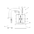
- the present invention relates to a dynamometer device for performing performance evaluation and testing of a vehicle power train, an engine, and the like, and more particularly to an improvement of a dynamometer device having a torque meter between a main shaft of a dynamometer and a specimen.
- the torque meter includes a pair of flanges,
- the heat insulating plate is disposed between the flange surface of the second rotating member to which one flange of the torque meter is attached and the flange surface of the first rotating member at the tip of the main shaft,
- the first rotating member and the second rotating member are coupled to each other by a plurality of bolts that penetrate the heat insulating plate.
- the heat insulating plate has an annular shape with a circular opening in the center,
- the circular protrusion provided in one inner peripheral portion of the first rotating member and the second rotating member, the circular recess provided in the other inner peripheral portion, and the opening are fitted to each other. Match.
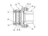
- FIG. 5 is a cross-sectional view showing a coupled state of these members (excluding the second heat insulating plate 26).
- the heat insulating plate 25 is made of a non-metallic heat insulating plate which is commercially available as a so-called high strength heat insulating plate having high heat insulating properties and high strength, and is formed in an annular shape corresponding to the flange surface 33a as shown in FIG. Has been.
- a plurality of bolt through holes 37 are formed corresponding to the bolt through holes 35 of the coupling 21.
- the inner diameter of the heat insulating plate 25, that is, the diameter of the circular opening 38 corresponds to the diameter of the stepped portion 36 of the coupling 21, and the opening 38 is fitted into the stepped portion 36 relatively tightly.
- the heat insulating plate 25 is positioned.
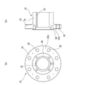
- the adapter flange 22 has an annular shape with an opening 44 at the center, and a plurality of screw holes 39 into which the bolts 34 are screwed.
- the outer peripheral side portion including the screw hole 39 is an annular flange surface 22 a in contact with the heat insulating plate 25.
- a circular recess 40 into which the front end surface of the step portion 36 is fitted corresponds to the step portion 36 of the coupling 21. Is formed.
- a torque meter mounting seat surface 41 is formed in an annular shape on the surface of the torque meter 24 shown in FIG. 8B, and a bolt 42 (see FIG. 5) for mounting the torque meter 24 is screwed together.
- a plurality of screw holes 43 are formed.
- At least one of the flange surfaces 33a and 22a in contact with the heat insulating plate 25 is provided with a ceramic sprayed layer that becomes a heat insulating layer by ceramic spraying.
- a ceramic sprayed layer made of zirconia and having a thickness of 0.5 mm is provided on the flange surface 33a on the coupling 21 side.
- the ceramic sprayed layer is continuously provided from the inner peripheral end of the flange surface 33 a to the outer peripheral surface of the stepped portion 36.
- the outer peripheral surface of the stepped portion 36 is fitted to the inner peripheral surface of the concave portion 40 of the adapter flange 22, and the diameter dimensions of both are set in consideration of the thickness (0.5 mm) of the ceramic sprayed layer.
- the inner peripheral surface of the recess 40 is fitted with high accuracy on the ceramic sprayed layer on the outer peripheral surface of the step portion 36.
- the sensor unit 49 includes a temperature sensor that detects the temperature of the torque meter 24 itself for calibration of temperature drift. Similarly, a temperature signal is output to the stator unit 27. As described above, in the air conditioner 11, the blowing temperature is variably controlled according to the temperature of the torque meter 24. In addition to the temperature sensor of the torque meter 24 itself, a temperature sensor for detecting the temperature inside the cover 7 or the temperature in the vicinity of the torque meter 24 is provided, and the air conditioner 11 is controlled based on the detected temperature. May be.
- the second flange 48 of the torque meter 24 has a plurality of circular through holes 52 for allowing the bolts 42 to pass therethrough, and a bolt 47 that couples the second flange 48 and the coupling flange 23 is screwed together.
- a plurality of screw holes 53 are provided. The through holes 52 and the screw holes 53 are alternately arranged in the circumferential direction.
- the pair of movable halves 64 ⁇ / b> A and 64 ⁇ / b> B are basically symmetrical with each other, and have a side wall 65 that forms the side wall surface of the cover 7 and a top surface of the cover 65 together with the fixed top wall 62.
- a top wall 66 provided along the edge, a bottom wall 67 provided along the lower edge of the side wall 65 so as to form a bottom surface of the cover 7 continuously to the side edge of the support base 28,
- a first front wall 68 formed over one end edge of the top wall 66, one end edge of the bottom wall 67, and a side edge of the side wall 65 so as to constitute a part of the front surface;
- a second front wall 69 superimposed on the (front surface).
Landscapes
- Physics & Mathematics (AREA)
- General Physics & Mathematics (AREA)
- Chemical & Material Sciences (AREA)
- Engineering & Computer Science (AREA)
- Health & Medical Sciences (AREA)
- Power Engineering (AREA)
- Life Sciences & Earth Sciences (AREA)
- Analytical Chemistry (AREA)
- Biochemistry (AREA)
- General Health & Medical Sciences (AREA)
- Immunology (AREA)
- Pathology (AREA)
- Combustion & Propulsion (AREA)
- Testing Of Devices, Machine Parts, Or Other Structures Thereof (AREA)
- Testing Of Engines (AREA)
Abstract
L'invention concerne un dynamomètre (3) comportant une plaque d'isolation thermique (25) intercalée entre un accouplement (21) et une bride d'adaptateur (22) d'un arbre principal (6) du dynamomètre. Un torsiomètre (24) est disposé entre une bride d'accouplement (23), qui sert de surface de liaison d'échantillon (56), et la bride d'adaptateur (22). Un couvercle (7) est disposé de façon à entourer la périphérie des éléments susmentionnés, et de l'air froid est introduit dans un espace interne du couvercle (7) par un climatiseur selon un cycle de réfrigération. La plaque d'isolation thermique (25) supprime le transfert de chaleur d'un moteur électrique du dynamomètre (3) au torsiomètre (24) ; par conséquent, le torsiomètre (24) est refroidi efficacement par l'air froid.
Priority Applications (2)
| Application Number | Priority Date | Filing Date | Title |
|---|---|---|---|
| KR1020197032081A KR102111341B1 (ko) | 2017-04-26 | 2018-04-06 | 다이나모미터 장치 |
| US16/607,814 US10852204B2 (en) | 2017-04-26 | 2018-04-06 | Dynamometer device |
Applications Claiming Priority (2)
| Application Number | Priority Date | Filing Date | Title |
|---|---|---|---|
| JP2017086744A JP6424921B2 (ja) | 2017-04-26 | 2017-04-26 | ダイナモメータ装置 |
| JP2017-086744 | 2017-04-26 |
Publications (1)
| Publication Number | Publication Date |
|---|---|
| WO2018198716A1 true WO2018198716A1 (fr) | 2018-11-01 |
Family
ID=63918306
Family Applications (1)
| Application Number | Title | Priority Date | Filing Date |
|---|---|---|---|
| PCT/JP2018/014654 Ceased WO2018198716A1 (fr) | 2017-04-26 | 2018-04-06 | Dispositif à dynamomètre |
Country Status (4)
| Country | Link |
|---|---|
| US (1) | US10852204B2 (fr) |
| JP (1) | JP6424921B2 (fr) |
| KR (1) | KR102111341B1 (fr) |
| WO (1) | WO2018198716A1 (fr) |
Families Citing this family (1)
| Publication number | Priority date | Publication date | Assignee | Title |
|---|---|---|---|---|
| JP7376778B2 (ja) * | 2019-11-01 | 2023-11-09 | シンフォニアテクノロジー株式会社 | 回転試験装置 |
Citations (5)
| Publication number | Priority date | Publication date | Assignee | Title |
|---|---|---|---|---|
| JPH0250173B2 (fr) * | 1981-09-24 | 1990-11-01 | Toyota Motor Co Ltd | |
| JP2012528301A (ja) * | 2009-05-26 | 2012-11-12 | ホリバ ヨーロッパ ゲーエムベーハー | 温度制御式冷却ブロワを有する試験台 |
| WO2013111685A1 (fr) * | 2012-01-23 | 2013-08-01 | 株式会社明電舎 | Dispositif d'essai de transmission |
| JP2015021560A (ja) * | 2013-07-18 | 2015-02-02 | 日本精工株式会社 | 自己潤滑性複合材料、並びにそれを用いた転がり軸受 |
| JP5942543B2 (ja) * | 2012-03-30 | 2016-06-29 | シンフォニアテクノロジー株式会社 | 供試体試験装置 |
Family Cites Families (9)
| Publication number | Priority date | Publication date | Assignee | Title |
|---|---|---|---|---|
| DE3306896A1 (de) * | 1983-02-26 | 1984-08-30 | MTU Motoren- und Turbinen-Union München GmbH, 8000 München | Heissgasbeaufschlagte turbinenschaufel mit metallenem stuetzkern und umgebendem keramischen schaufelblatt |
| JPS60175848A (ja) | 1984-02-22 | 1985-09-10 | Aisin Warner Ltd | 複数歯車同時係止式パーキング機構付変速機 |
| JPS60175848U (ja) * | 1984-04-27 | 1985-11-21 | 日産ディーゼル工業株式会社 | 内燃機関の断熱ピストン |
| CA2190697C (fr) * | 1996-01-31 | 2000-07-25 | Donald Glenn Larson | Moteur a avance reglable |
| JP4531930B2 (ja) * | 2000-05-19 | 2010-08-25 | 黒崎播磨株式会社 | 高耐用性断熱材及びその製造方法並びにその用途およびその施工方法 |
| JP2003130751A (ja) | 2001-10-29 | 2003-05-08 | Meidensha Corp | 自動車部品の試験装置 |
| WO2007008225A2 (fr) * | 2004-08-14 | 2007-01-18 | The State Of Oregon Acting By And Through The State Board Of Higher Education On Behalf Of Oregon State University | Systemes de pompe a chaleur activee par la chaleur, comprenant un compresseur/detendeur et un regenerateur integres |
| KR20130130557A (ko) | 2012-05-22 | 2013-12-02 | 현대모비스 주식회사 | 차량의 좁은 길 통과 보조 장치 및 그 방법 |
| US9752961B2 (en) * | 2014-06-19 | 2017-09-05 | Avl Test Systems, Inc. | Dual-purpose dynamometer |
-
2017
- 2017-04-26 JP JP2017086744A patent/JP6424921B2/ja active Active
-
2018
- 2018-04-06 KR KR1020197032081A patent/KR102111341B1/ko active Active
- 2018-04-06 US US16/607,814 patent/US10852204B2/en active Active
- 2018-04-06 WO PCT/JP2018/014654 patent/WO2018198716A1/fr not_active Ceased
Patent Citations (5)
| Publication number | Priority date | Publication date | Assignee | Title |
|---|---|---|---|---|
| JPH0250173B2 (fr) * | 1981-09-24 | 1990-11-01 | Toyota Motor Co Ltd | |
| JP2012528301A (ja) * | 2009-05-26 | 2012-11-12 | ホリバ ヨーロッパ ゲーエムベーハー | 温度制御式冷却ブロワを有する試験台 |
| WO2013111685A1 (fr) * | 2012-01-23 | 2013-08-01 | 株式会社明電舎 | Dispositif d'essai de transmission |
| JP5942543B2 (ja) * | 2012-03-30 | 2016-06-29 | シンフォニアテクノロジー株式会社 | 供試体試験装置 |
| JP2015021560A (ja) * | 2013-07-18 | 2015-02-02 | 日本精工株式会社 | 自己潤滑性複合材料、並びにそれを用いた転がり軸受 |
Also Published As
| Publication number | Publication date |
|---|---|
| KR102111341B1 (ko) | 2020-06-04 |
| US10852204B2 (en) | 2020-12-01 |
| JP6424921B2 (ja) | 2018-11-21 |
| KR20190130637A (ko) | 2019-11-22 |
| US20200191671A1 (en) | 2020-06-18 |
| JP2018185216A (ja) | 2018-11-22 |
Similar Documents
| Publication | Publication Date | Title |
|---|---|---|
| JP5333612B2 (ja) | 変速機の試験装置 | |
| KR101951892B1 (ko) | 온도제어 테스트 장치 및 방법 | |
| CN212932679U (zh) | 一种可调式速度传感器性能测试装置 | |
| WO2018198716A1 (fr) | Dispositif à dynamomètre | |
| CN204461637U (zh) | 一种热电偶测温装置 | |
| JP2010027729A (ja) | プローブ装置及びそれを用いた半導体ウェハの検査方法 | |
| CN110887590A (zh) | 一种高速轴承摩擦试验机 | |
| CN119533769B (zh) | 高温超导托卡马克杜瓦环体测量设备及应用方法 | |
| JP2015064223A (ja) | 環境試験装置 | |
| CN216350272U (zh) | 基于能量法的材料辐射性能测量装置 | |
| CN103649614B (zh) | 检测探头安装装置、包括其的壳体和机器及其维修方法 | |
| CN116678623A (zh) | 一种航空发动机及燃气轮机测试探针转向测量系统 | |
| CN211175057U (zh) | 集成有传感器的主轴轴承结构 | |
| US7743663B2 (en) | Sensor Unit | |
| JP6592396B2 (ja) | 検出装置、軸受試験装置および車両 | |
| JP6534453B2 (ja) | 圧延装置及び圧延装置の改造方法 | |
| KR102405786B1 (ko) | 보일러 화염측 상태감지 장치 및 이를 이용한 시스템 | |
| US20180149524A1 (en) | System for protecting a thermocouple | |
| CN114764030A (zh) | 探温机构及具有该探温机构的镀膜设备 | |
| CN112212171A (zh) | 一种温箱转台俯仰轴系温度影响消除设计 | |
| CN121498875A (zh) | 测温装置、实验装置及测温方法 | |
| JPH0325733B2 (fr) | ||
| CN115753599A (zh) | 基于能量法的材料辐射性能测量装置 | |
| CN114636633A (zh) | 高低温试验装置及其环境温度调节方法 | |
| JPH04221731A (ja) | 釣合い試験機用の回転体の基準位置検出装置 |
Legal Events
| Date | Code | Title | Description |
|---|---|---|---|
| 121 | Ep: the epo has been informed by wipo that ep was designated in this application |
Ref document number: 18791368 Country of ref document: EP Kind code of ref document: A1 |
|
| ENP | Entry into the national phase |
Ref document number: 20197032081 Country of ref document: KR Kind code of ref document: A |
|
| NENP | Non-entry into the national phase |
Ref country code: DE |
|
| 122 | Ep: pct application non-entry in european phase |
Ref document number: 18791368 Country of ref document: EP Kind code of ref document: A1 |