WO2018198750A1 - Boîte d'emballage - Google Patents
Boîte d'emballage Download PDFInfo
- Publication number
- WO2018198750A1 WO2018198750A1 PCT/JP2018/015013 JP2018015013W WO2018198750A1 WO 2018198750 A1 WO2018198750 A1 WO 2018198750A1 JP 2018015013 W JP2018015013 W JP 2018015013W WO 2018198750 A1 WO2018198750 A1 WO 2018198750A1
- Authority
- WO
- WIPO (PCT)
- Prior art keywords
- wall
- bottom wall
- state
- wall body
- end wall
- Prior art date
- Legal status (The legal status is an assumption and is not a legal conclusion. Google has not performed a legal analysis and makes no representation as to the accuracy of the status listed.)
- Ceased
Links
Images


Classifications
-
- B—PERFORMING OPERATIONS; TRANSPORTING
- B65—CONVEYING; PACKING; STORING; HANDLING THIN OR FILAMENTARY MATERIAL
- B65D—CONTAINERS FOR STORAGE OR TRANSPORT OF ARTICLES OR MATERIALS, e.g. BAGS, BARRELS, BOTTLES, BOXES, CANS, CARTONS, CRATES, DRUMS, JARS, TANKS, HOPPERS, FORWARDING CONTAINERS; ACCESSORIES, CLOSURES, OR FITTINGS THEREFOR; PACKAGING ELEMENTS; PACKAGES
- B65D5/00—Rigid or semi-rigid containers of polygonal cross-section, e.g. boxes, cartons or trays, formed by folding or erecting one or more blanks made of paper
- B65D5/20—Rigid or semi-rigid containers of polygonal cross-section, e.g. boxes, cartons or trays, formed by folding or erecting one or more blanks made of paper by folding-up portions connected to a central panel from all sides to form a container body, e.g. of tray-like form
- B65D5/22—Rigid or semi-rigid containers of polygonal cross-section, e.g. boxes, cartons or trays, formed by folding or erecting one or more blanks made of paper by folding-up portions connected to a central panel from all sides to form a container body, e.g. of tray-like form held erect by extensions of one or more sides being doubled-over to enclose extensions of adjacent sides
-
- B—PERFORMING OPERATIONS; TRANSPORTING
- B65—CONVEYING; PACKING; STORING; HANDLING THIN OR FILAMENTARY MATERIAL
- B65D—CONTAINERS FOR STORAGE OR TRANSPORT OF ARTICLES OR MATERIALS, e.g. BAGS, BARRELS, BOTTLES, BOXES, CANS, CARTONS, CRATES, DRUMS, JARS, TANKS, HOPPERS, FORWARDING CONTAINERS; ACCESSORIES, CLOSURES, OR FITTINGS THEREFOR; PACKAGING ELEMENTS; PACKAGES
- B65D5/00—Rigid or semi-rigid containers of polygonal cross-section, e.g. boxes, cartons or trays, formed by folding or erecting one or more blanks made of paper
- B65D5/32—Rigid or semi-rigid containers of polygonal cross-section, e.g. boxes, cartons or trays, formed by folding or erecting one or more blanks made of paper having bodies formed by folding and interconnecting two or more blanks
-
- B—PERFORMING OPERATIONS; TRANSPORTING
- B65—CONVEYING; PACKING; STORING; HANDLING THIN OR FILAMENTARY MATERIAL
- B65D—CONTAINERS FOR STORAGE OR TRANSPORT OF ARTICLES OR MATERIALS, e.g. BAGS, BARRELS, BOTTLES, BOXES, CANS, CARTONS, CRATES, DRUMS, JARS, TANKS, HOPPERS, FORWARDING CONTAINERS; ACCESSORIES, CLOSURES, OR FITTINGS THEREFOR; PACKAGING ELEMENTS; PACKAGES
- B65D5/00—Rigid or semi-rigid containers of polygonal cross-section, e.g. boxes, cartons or trays, formed by folding or erecting one or more blanks made of paper
- B65D5/42—Details of containers or of foldable or erectable container blanks
- B65D5/44—Integral, inserted or attached portions forming internal or external fittings
Definitions
- the present invention relates to a packaging box.
- a packaging box that contains the contents and can be stacked up and down is known.
- the packaging box described in Patent Document 1 includes a rectangular bottom wall, a pair of end walls provided in a standing posture on the short side of the bottom wall, and a pair of side walls provided in a standing posture on the long side of the bottom wall. And.
- An inner wall is fixed to the inner surface of the end wall, and insertion locking portions are provided at lower portions on both sides of the end wall and the inner wall.
- the inner wall is provided with a reinforcing wall that constitutes a support having a triangular cross section when the packaging box is assembled.
- the side wall is formed in a double wall structure with an outer plate portion and an inner plate portion, and an insertion locking portion is sandwiched and fixed between the outer plate portion and the inner plate portion.
- a locking projection that is locked to a locking hole that opens in the bottom wall is formed at the tip of the inner plate.
- the present invention provides a packaging box that maintains a state in which a side wall sandwiches an extension.
- the present invention is a packaging box that can be stacked in a plurality of layers, and includes a bottom wall body including an engagement recess formed in a recessed state on the surface, and a peripheral edge of the bottom wall body.
- An end wall body arranged in a standing posture, and a side wall body arranged in a standing posture on a peripheral edge portion of the bottom wall body at a position adjacent to the end wall body and shifted from the end wall body in the circumferential direction.
- the end wall body includes a support wall provided in a state of projecting inward and an extension provided in a state of extending toward the side wall body, and the side wall body includes the bottom wall body.
- the outer plate portion provided in a state extending upward from the peripheral portion of the outer plate portion and the extension portion between the outer plate portion and the outer plate portion folded back downward so as to cover the upper portion of the extension portion. It is provided in a state where it is connected to the inner plate portion to be sandwiched and the tip portion of the inner plate portion, and the outer plate portion and the inner plate portion In serial sandwiched extension state includes a engaging portion for engaging the engagement recess in a posture along the bottom wall.
- an engagement piece portion that engages with an engagement groove formed in the end wall body in a state where the engagement convex portion is engaged with the engagement concave portion. Is preferably formed.
- the packaging box is formed of a corrugated cardboard sheet in which a liner is bonded to a middle liner, and the bottom wall body is formed with a lower bottom wall formed in a state of being connected to the outer plate portion, and the lower wall An upper bottom wall formed separately from the bottom wall, disposed above the lower bottom wall and formed with a defect portion constituting the engaging recess, and the middle shin of the lower bottom wall It is preferable that the middle shin of the upper bottom wall extends in a direction crossing each other.
- the bottom wall body further includes an intermediate bottom wall formed in a state of being connected to the end wall body, and the intermediate bottom wall is formed separately from the lower bottom wall and the upper bottom wall. And is preferably fixed in a state of being sandwiched between the lower bottom wall and the upper bottom wall.
- the packaging box is formed of a corrugated cardboard sheet in which a liner is bonded to a middle shin, and the middle shin of each of the end wall body, the outer plate portion, and the inner plate portion extends in the vertical direction. It is preferable.
- the upper end surface of the support wall is provided below the uppermost end surface of the end wall body, and the end wall body is formed so as to gradually become wider from below to above. .
- the end wall body includes an outer end wall disposed in a standing posture at a peripheral edge portion of the bottom wall body, and an outer edge provided in a state extending from the side end portion of the outer end wall toward the side wall body.
- the support wall is provided in a state where it is connected to the inner end wall via a first folding curve, and is connected to the inner edge wall via a second folding curve.
- a third folding line extending in parallel with the first folding line and the second folding curve between the first folding line and the second folding curve, wherein the support wall defines the inner edge wall as the first folding line.
- the end wall body includes a first folded wall provided in a state of being connected to a side end portion of the outer edge wall via a first folded line, and a second folded line at an upper end portion of the outer edge wall.
- a second folded wall provided in a state of being connected via an inner end wall, wherein the inner end wall is provided in a state of being connected to an upper end portion of the outer end wall via a third return line.
- the inner wall of the outer edge wall is overlapped with the inner wall of the outer end wall by being folded inward along the third folding line, and the inner wall of the outer edge wall is folded inward along the first folding line. It is preferable that the overlapped inner edge wall is fixed while being overlapped, and the second folded wall is overlapped and fixed to the inner surface of the outer edge wall in a state of being folded inward along the second folded line.
- an end piece body is provided in a state of being connected to a peripheral edge portion of the bottom wall body on which the end wall body is disposed, and a second surface is provided on the surface of the bottom wall body on the end wall body side.
- the end piece body is provided in a state extending upward from a peripheral edge portion of the bottom wall body, the outer piece portion overlapping the outer surface of the end wall body, and the outer An inner piece portion that is folded downward with respect to the one piece portion and sandwiches at least a part of the end wall body between the outer piece portion and a tip portion of the inner piece portion.
- a side extension of the outer piece portion is provided in a state where a second extension portion is continuous, and the second extension portion extends together with the extension portion in a state of extending toward the side wall body. It is preferable to be sandwiched between the outer plate portion and the inner plate portion.
- the support wall is formed with a laminated protrusion protruding upward from the upper end portion, and the bottom wall body has the laminated protrusion of the lower packaging box when a plurality of packaging boxes are laminated. It is preferable that a laminated hole to be inserted is formed.
- the end wall body is connected to an outer end wall arranged in a standing posture on a peripheral edge portion of the bottom wall body, and is connected to a side end portion of the outer end wall via a side ruled line.
- An outer edge wall provided in a state extending from a side end portion of the wall toward the side wall body; and an inner end wall superimposed on an inner surface of the outer end wall, wherein the extension portion is a tip of the outer edge wall.
- the support wall is provided in a state connected to the inner end wall via a first folding curve, and has a second folding curve extending in parallel with the first folding curve.
- a fixed wall fixed to the outer end wall along the side ruled line in a state of being folded at the third folding curve, and the fixed wall A diagonal wall having a laminated projection protruding upward from the main body wall, the support wall being formed by connecting the main body wall to the first main wall.
- a strut having a rectangular cross section by causing a fold at a folding line and a fold at the second fold curve, a fold at the third fold curve and a fold at a fourth fold curve,
- the diagonal wall is disposed in a state where the diagonal wall is bent at the fifth folding curve and extends toward the third folding curve, and the stacked projection protrudes above the upper end surface of the column, and the bottom wall
- the body is preferably formed with a laminated hole into which the laminated protrusion of the lower packaging box is inserted when a plurality of packaging boxes are laminated.
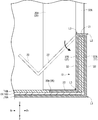
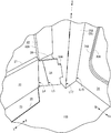
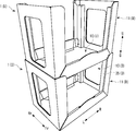
- FIG. 5 is a perspective view showing an end wall body or the like of the stacking tray according to the first embodiment of the present invention and showing a state in the middle of the first step. It is a disassembled perspective view which shows the stacking tray which concerns on 1st Embodiment of this invention.
- FIG. 2 is a sectional view taken along line IX-IX in FIG. It is a perspective view which expands and shows the engagement piece part etc. of the stacking tray which concerns on 1st Embodiment of this invention. It is a perspective view which shows the state which accumulated the stacking tray which concerns on 1st Embodiment of this invention.
- FIG. 10 is a plan view showing an engaging convex portion and an engaging concave portion of a stacking tray according to a first modification of the first to third embodiments of the present invention.
- FIG. 10 is a plan view showing an engaging convex portion and an engaging concave portion of a stacking tray according to a second modification of the first to third embodiments of the present invention.
- FIG. 10 is a plan view showing an engaging convex portion and an engaging concave portion of a stacking tray according to a third modification of the first to third embodiments of the present invention.
- FIG. 10 is a plan view showing an engaging convex portion and an engaging concave portion of a stacking tray according to a third modification of the first to third embodiments of the present invention.
- FIG. 10 is a plan view showing an engaging convex portion and an engaging concave portion of a stacking tray according to a fourth modification of the first to third embodiments of the present invention. It is a perspective view which shows the stacking tray which concerns on 4th Embodiment of this invention. It is a top view which shows the 1st and 2nd blank of the stacking tray which concerns on 4th Embodiment of this invention. It is a top view which shows the 3rd blank of the stacking tray which concerns on 4th Embodiment of this invention. It is a perspective view which shows the state which the connection process of the stacking tray which concerns on 4th Embodiment of this invention was completed. It is a perspective view which expands and shows the support wall etc.
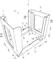
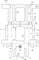
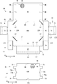
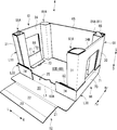
- FIG. 1 is a perspective view showing a stacking tray 1.
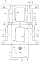
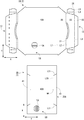
- FIG. 2 is a plan view showing the first and second blanks 1A and 1B of the stacking tray 1.
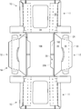
- FIG. 3 is a plan view showing the third blank 1 ⁇ / b> C of the stacking tray 1.
- the stacking tray 1 has an opening 13 that is continuous from the upper surface to the front and rear surfaces, and is formed in a substantially rectangular parallelepiped shape.
- the stacking tray 1 is formed such that a plurality of stacking trays 1 can be stacked up and down with contents (not shown) such as products placed on the bottom wall body 10.
- Four struts 35 ⁇ / b> A extending in the vertical direction are provided at the four corners inside the stacking tray 1.
- Each support 35 ⁇ / b> A abuts against the bottom wall body 10 of the stacking tray 1 stacked above and supports the upper stacking tray 1.
- the stacking tray 1 includes a pair of end wall bodies 11 and a pair of side wall bodies 12 arranged in a standing posture on the peripheral edge of the bottom wall body 10.
- the bottom wall body 10 is formed in a substantially rectangular shape that is long in the left-right direction when viewed from the plane. Although details will be described later, the bottom wall body 10 is formed by laminating a lower bottom wall 10A, a pair of left and right intermediate bottom walls 10C, and an upper bottom wall 10B.
- the pair of end wall bodies 11 opposes in the left-right direction across the bottom wall body 10, and the pair of side wall bodies 12 opposes in the front-rear direction across the bottom wall body 10.
- the side wall body 12 is disposed in a standing posture at a position adjacent to the end wall body 11 by being shifted from the end wall body 11 by approximately 90 degrees in the circumferential direction.
- the end wall body 11 is formed higher (longer in the vertical direction) than the side wall body 12.
- the stacking tray 1 is formed by connecting and assembling the first to third blanks 1A, 1B, and 1C shown in FIGS.
- Each of the first to third blanks 1A, 1B, and 1C is formed by punching one sheet of cardboard sheet with a die cutter or the like.
- the corrugated cardboard sheet is, for example, a double-faced cardboard in which a front liner 5B and a back liner 5C (see FIG. 4) are bonded to the front and back of a corrugated shin 5A. 2 and 3 show the front liner 5B side.
- step direction the direction parallel to the central shin 5A of the corrugated cardboard sheet
- flow direction the direction orthogonal to the step direction
- “X” indicates “stage direction”
- Y” indicates “flow direction”.
- the first blank 1 ⁇ / b> A includes a lower bottom wall 10 ⁇ / b> A and a pair of side wall bodies 12.
- 10 A of lower bottom walls are formed in the state connected with a pair of side wall body 12 (outer plate part 20).
- a pair of side wall body 12 is formed in the step direction substantially symmetrically on both sides of 10 A of lower bottom walls, the one side wall body 12 (right side in FIG. 2) is demonstrated below.
- ⁇ Lower bottom wall> 10 A of lower bottom walls are formed in the substantially rectangular shape long in a flow direction.
- a lower mark M1 is formed at the center and both ends of the step direction of the lower bottom wall 10A.
- lower marks M1 are formed at the four corners of the lower bottom wall 10A.
- the lower mark M1 is formed by a cutting line that penetrates the blade in the thickness direction of the cardboard sheet.
- the side wall body 12 includes an outer plate portion 20, an upper plate edge portion 21, an inner plate portion 22, and an engaging convex portion 23.
- the outer plate portion 20 is provided in a state of being connected to one end in the step direction of the lower bottom wall 10A via the first ruled line L1.
- the inner plate portion 22 is provided in a state of being connected to the side end portion (tip portion) of the outer plate portion 20 via two second ruled lines L2.
- An upper plate edge 21 is formed between the two second ruled lines L2.
- the engaging convex portion 23 is provided in a state of being connected to a side end portion (tip end portion) of the inner plate portion 22 via a fitting folding line L3.
- the first and second ruled lines L1 and L2 are general ruled lines formed by crushing a cardboard sheet in the thickness direction from the back liner 5C side.
- the fitting fold line L3 is a lead ruler in which a plurality of cutting lines are formed at predetermined intervals on a reverse ruled line formed by crushing a cardboard sheet in the thickness direction from the front liner 5B side.
- the outer plate portion 20 is formed in a substantially trapezoidal shape that becomes narrower in the flow direction from the base end (lower bottom wall 10A side) to the tip end (upper plate edge portion 21 side). For this reason, inclined portions 20 ⁇ / b> A are formed at both ends (side ends) in the flow direction of the outer plate portion 20 so as to be inclined toward each other from the proximal end toward the distal end.
- the dimension in the step direction (projection dimension) of the outer plate portion 20 is set to be shorter (for example, about 1/4) than the dimension in the step direction of the lower bottom wall 10A.
- the upper plate edge portion 21 is formed in a substantially rectangular shape that is long in the flow direction, and the outer plate portion 20 and the inner plate portion 22 are made continuous.
- the dimension of the upper plate edge portion 21 in the flow direction is set to be substantially the same as the length of the side edge of the outer plate portion 20.
- the protruding dimension of the upper plate edge 21 is set slightly longer than the thickness of the corrugated cardboard sheet.
- a curved hole 21 ⁇ / b> A that is curved so as to protrude beyond the second ruled line L ⁇ b> 2 and protrude into the inner plate portion 22 is opened in the center region in the flow direction of the upper plate edge portion 21.
- the curved hole 21 ⁇ / b> A is formed with substantially the same width as the protruding dimension of the upper plate edge 21.
- the upper plate edge portion 21 is formed with an arch convex portion 21B extending from the outer plate portion 20 along the contour of the curved hole 21A.
- the 2nd ruled line L2 is not formed in the arch convex part 21B.
- the arch convex part 21B (curved hole 21A) constitutes the design of the stacking tray 1, it may be omitted if unnecessary.
- the inner plate portion 22 is formed in a substantially trapezoidal shape that becomes narrower in the flow direction from the base end (upper plate edge portion 21 side) to the tip end (engagement convex portion 23 side).
- the dimension of the inner plate portion 22 in the flow direction is set to be approximately the same as the dimension of the upper plate edge portion 21 in the flow direction.
- the protruding dimension of the inner plate part 22 is set shorter than the protruding dimension of the outer plate part 20 by the thickness of about two cardboard sheets.
- a pair of engagement piece portions 24 are formed at both ends of the inner plate portion 22 in the flow direction.
- the pair of engaging piece portions 24 extend outward from both ends in the flow direction of the inner plate portion 22.
- a first engagement folding line L4 is formed at the boundary between each engagement piece 24 and the inner plate portion 22.
- Each engagement piece 24 is formed with a second engagement fold line L5 on the outer side in the flow direction than the first engagement fold line L4.
- the pair of first engagement folding lines L4 are inclined in a direction in which they approach each other from the proximal end of the inner plate portion 22 toward the distal end.
- the pair of second engagement folding lines L5 are each formed substantially parallel to the step direction.
- an engaging protrusion 24A protrudes outward from the outer end of each engaging piece 24 in the flow direction.
- the first and second engagement folding lines L4 and L5 are lead rules in which a plurality of cutting lines are formed at predetermined intervals on a ruled line formed by crushing a corrugated cardboard sheet from the front and back surfaces
- the engaging convex part 23 is formed in a substantially trapezoidal shape that becomes narrower in the flow direction from the base end (inner plate part 22 side) to the front end (free end).
- the dimension of the engaging convex portion 23 in the flow direction is set to be substantially the same as the length of the side end side of the inner plate portion 22.
- the projecting dimension of the engaging convex part 23 is set shorter (for example, about half) than the projecting dimension of the inner plate part 22.
- the protrusion dimension of the engagement convex part 23 may be substantially the same as the protrusion dimension of the inner plate part 22, or may be slightly longer.
- the second blank 1B includes an upper bottom wall 10B.
- the upper bottom wall 10B is slightly smaller than the lower bottom wall 10A and is formed in a substantially rectangular shape that is long in the step direction.
- a pair of missing portions 25A are formed so as to be recessed inward.
- the pair of missing portions 25A are cut out in a substantially trapezoidal shape that becomes narrower in the step direction from both ends in the flow direction of the upper bottom wall 10B.
- the missing portion 25 ⁇ / b> A is formed to have substantially the same shape (complementary shape) as the engaging convex portion 23.
- the upper bottom wall 10B is disposed above the lower bottom wall 10A, and each of the missing portions 25A is fitted with the engagement convex portion 23.
- An engaging recess 25 is provided for this purpose.
- the third blank 1 ⁇ / b> C includes an intermediate bottom wall 10 ⁇ / b> C and an end wall body 11.
- the stacking tray 1 is assembled, two third blanks 1C are used, and a pair of left and right end wall bodies 11 are formed. Since the two third blanks 1C (the pair of end wall bodies 11) have the same shape, only one third blank 1C (one end wall body 11) will be described below.
- intermediate bottom wall> 10 C of intermediate middle bottom walls are formed in the state connected to the step direction one end part (lower end part in an assembly state) of the end wall body 11 (after-mentioned outer end wall 30) via the downward ruled line L10.
- the intermediate bottom wall 10C is formed in a substantially rectangular shape.
- the dimension in the step direction of the intermediate bottom wall 10C is set to about half of the dimension in the flow direction of the lower bottom wall 10A.
- the dimension in the flow direction of the intermediate bottom wall 10C is set to be substantially the same as the dimension in the step direction of the lower bottom wall 10A.
- a first intermediate mark M2 is formed at the center in the flow direction at one end (free end) in the step direction of the intermediate bottom wall 10C.
- first intermediate mark M2 is also formed at two corners (near both ends of the lower ruled line L10) at the other end in the step direction of the intermediate bottom wall 10C.
- second intermediate marks M3 are formed in the central region in the step direction of the intermediate bottom wall 10C.
- the first and second intermediate marks M2, M3 are formed by cutting lines.
- the end wall body 11 includes an outer end wall 30, a pair of outer edge walls 31, a pair of first folded walls 32, a pair of second folded walls 33, an inner end wall 34, a pair of support walls 35, A pair of inner edge walls 36.
- the end wall body 11 is formed so as to extend in the step direction as a whole.
- the outer end wall 30 is provided in a state of being connected to the boundary with the intermediate bottom wall 10C via a lower ruled line L10.
- the pair of outer edge walls 31 are provided in a state of being connected to both ends in the flow direction of the outer end wall 30 via side ruled lines L11.
- the pair of first folding walls 32 are respectively provided in a state of being connected to the outer end of the outer edge wall 31 in the flow direction via two first folding lines L12.
- a first edge portion 32A is formed between the two first return lines L12.
- the pair of second folding walls 33 are respectively provided in a state of being connected to the other end in the step direction of the outer edge wall 31 (upper end in the assembled state) via two second folding lines L13.
- a second edge 33A is formed between the two second return lines L13.
- the inner end wall 34 is provided in a state of being connected to the other end portion in the step direction of the outer end wall 30 (upper end portion in the assembled state) via the third return line L14.
- the pair of support walls 35 are provided in a state of being connected to both ends of the inner end wall 34 in the flow direction via the first folding line L15.
- Each of the pair of inner edge walls 36 is provided in a state of being connected to the outer end portion in the flow direction of the support wall 35 via the second folding line L16.
- the lower ruled line L10, the side ruled lines L11, and the first to third return lines L12 to L14 are general ruled lines, respectively.
- the first and second folding lines L15 and L16 are lead rules in which a plurality of cutting lines are formed at predetermined intervals on the reverse ruled lines.
- end wall body 11 is formed substantially symmetrically in the flow direction across the center line extending in the step direction, hereinafter, one of the pair of walls 31, 32, 33, 35, 36 provided below. Will be described.
- the outer end wall 30 has a substantially rectangular outer shape that is long in the step direction. In the central region of the outer end wall 30, an outer end opening 30A having a substantially rectangular shape that is long in the step direction is opened. That is, the outer end wall 30 is formed in a substantially rectangular ring shape.
- the dimension (length in the flow direction) of the one end side (lower ruled line L10) in the step direction of the outer end wall 30 is set to be substantially the same as the dimension in the step direction of the lower bottom wall 10A.
- the dimension of the other end side in the step direction of the outer end wall 30 (third folded line L14) is set slightly longer than one end side of the outer end wall 30. That is, the outer shape of the outer end wall 30 is formed in a substantially trapezoidal shape that is slightly wider in the flow direction from one end in the step direction to the other end. In other words, the outer end wall 30 is formed so as to gradually become wider (longer in the flow direction) from below to above in the assembled state.
- Both ends of the outer end wall 30 in the flow direction (side ruled lines L11) are inclined outward by about 1 degree with respect to the center shin 5A (a line extending perpendicular to the lower ruled line L10).
- the outer edge wall 31 is formed in a substantially rectangular shape that is long in the step direction.
- the stepwise dimension of the outer edge wall 31 is set to be substantially the same as the stepwise dimension of the outer end wall 30.
- the dimension (projection dimension) of the outer edge wall 31 in the flow direction is set to be shorter (for example, about 1 ⁇ 4) than the dimension of the outer end wall 30 in the flow direction.
- the corner of the other end of the outer edge wall 31 is chamfered in an arc shape.
- a substantially rectangular outer extension 37 ⁇ / b> A is integrally formed on one end side (lower side in the assembled state) of the outer edge wall 31.
- the outer extension 37 ⁇ / b> A is provided in a state extending outward from the flow direction end (tip) of the outer edge wall 31. For this reason, the outer extension portion 37A and the outer edge wall 31 are formed in a substantially L shape as a whole.
- the first edge portion 32A is formed in a substantially rectangular shape that is long in the step direction, and the outer edge wall 31 and the first folded wall 32 are made continuous.
- the dimension in the step direction of the first edge portion 32A is set to be approximately the same as the length of the side edge of the outer edge wall 31 excluding the chamfered corner portion of the outer edge wall 31 and the outer extension portion 37A.
- the protruding dimension of the first edge portion 32A is set slightly longer than the thickness of the cardboard sheet.
- the first folding wall 32 is formed in a substantially rectangular shape having substantially the same dimension as the first edge portion 32A in the step direction.
- the projecting dimension of the first folding wall 32 is set longer than the first edge portion 32A.
- the corner of the other end of the first folded wall 32 is cut off. Note that the protruding dimension of the outer extension 37 ⁇ / b> A is set longer than the protruding dimension of the first folded wall 32.
- the second edge portion 33A is formed in a substantially rectangular shape, and the outer edge wall 31 and the second folded wall 33 are made continuous.
- the dimension in the flow direction of the second edge portion 33A is set to be substantially the same as the length of the other end side of the outer edge wall 31 excluding the chamfered corner portion of the outer edge wall 31.
- the dimension (projection dimension) in the step direction of the second edge portion 33A is set slightly longer than the thickness of the cardboard sheet.
- the second folding wall 33 is formed in a substantially rectangular shape having substantially the same dimension in the flow direction as the second edge 33A.
- the dimension (projection dimension) in the step direction of the second folding wall 33 is set longer than the second edge 33A.
- the corner of the other end of the second folded wall 33 is cut off.
- the inner end wall 34 has a substantially rectangular outer shape having substantially the same dimensions as the outer end wall 30 in the step direction.
- the inner end wall 34 has an inner end opening 34A having the same shape as the outer end opening 30A, and is formed in a substantially rectangular ring shape.
- the outer shape of the inner end wall 34 excluding the vicinity of the third return line L14 is formed in a substantially trapezoidal shape that becomes slightly narrower in the flow direction from one end in the step direction (the third return line L14 side) to the other end. Yes. That is, like the outer end wall 30, the inner end wall 34 is formed so as to gradually become wider (longer in the flow direction) from below to above in the assembled state.
- Both ends of the inner end wall 34 in the flow direction are inclined outward by about 1 degree with respect to the intermediate shin 5A (a line extending perpendicular to the third folding line L14).
- the second and third folding lines L16 and L17 are also inclined at the same angle as the first folding line L15.
- the support wall 35 is formed in a substantially rectangular shape that is long in the step direction.
- the support wall 35 is formed so as to bite into the inner end wall 34 side by extending a cutting line from the boundary with the second folded wall 33 toward the inner side of the inner end wall 34.
- the dimension in the step direction of the support wall 35 is set to be substantially the same as the dimension in the step direction of the inner end wall 34 excluding the second folding wall 33.
- the dimension (projection dimension) of the support wall 35 in the flow direction is set to be shorter (for example, about half) than the inner end wall 34.
- the support wall 35 is provided in a state connected to the inner end wall 34 via the first folding line L15 and in a state connected to the inner edge wall 36 via the second folding line L16.
- the support wall 35 is formed with a third folding line L17 extending in parallel with the first folding line L15 and the second folding line L16.
- the third folding line L17 is formed at a position close to the first folding line L15 between the first folding line L15 and the second folding line L16.
- the third folding line L17 is a lead ruled line in which a plurality of cutting lines are formed at predetermined intervals on the general-purpose ruled line.
- the interval between the first fold line L15 and the third fold line L17 is set to be substantially the same as the interval between the second fold line L16 and the extended line of the side ruled line L11.
- an engagement groove 38 is formed along the second folding line L16 on the other end side (lower side in the assembled state) of the support wall 35.
- the engagement groove 38 is a cutting line that extends slightly parallel to the second fold line L16 on the inner side (the third fold line L17 side) slightly from the second fold line L16.
- the support wall 35 is formed with a pair of cutting lines having the same width as the engagement groove 38 inward from the second folding line L16.
- a tongue-shaped cut piece 38A is formed in a range surrounded by the pair of cutting lines and the engaging groove 38.
- the inner edge wall 36 is formed in a substantially rectangular shape having substantially the same dimensions as the support wall 35 in the step direction.
- the dimension (projection dimension) of the inner edge wall 36 in the flow direction is set shorter (for example, about half) than the projection dimension of the outer edge wall 31. Further, the protruding dimension of the inner edge wall 36 is set to be substantially the same as the protruding dimension of the first folded wall 32.
- a substantially rectangular inner extension portion 37B is integrally formed on the other end side of the inner edge wall 36 (lower side in the assembled state).
- the inner extension 37 ⁇ / b> B is provided in a state extending outward from the flow direction end (tip) of the inner edge wall 36. For this reason, the inner side extension part 37B and the inner edge wall 36 are formed in the substantially L shape as a whole.
- the stacking tray 1 is assembled after connecting the first to third blanks 1A, 1B, 1C.
- the connecting process and the assembling process of the first to third blanks 1A, 1B, and 1C may be performed manually by an operator, or may be performed automatically or semi-automatically by a dedicated box making machine or the like.
- an operator performs a connection process or an assembly process manually will be described.
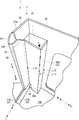
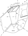
- FIG. 4 is a perspective view showing the state of the end wall body 11 and the like in the middle of the first step.
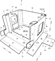
- FIG. 5 is an exploded perspective view showing the stacking tray 1.
- FIG. 6 is a plan view showing a state in which the connecting process of the stacking tray 1 is completed.
- an operator forms the end wall body 11 used for an assembly process (1st process). For example, the operator places the third blank 1C on the work table with the back liner 5C facing upward, and double-sided tape on the inner end wall 34 (around the inner end opening 34A) and each inner extension 37B. Affix (not shown). The double-sided tape is not affixed to the support wall 35.
- the operator folds (inverts) the inner end wall 34 toward the outer end wall 30 along the third fold line L14.
- the inner end wall 34 is overlapped on the inner surface (back liner 5C) of the outer end wall 30 and is bonded to the inner surface of the outer end wall 30 via a double-sided tape.
- the support wall 35 is overlapped on the inner surfaces (see FIG. 3) of the outer end wall 30 and the outer edge wall 31 across the side ruled line L11.
- the inner edge wall 36 is overlaid on the inner surface of the outer edge wall 31.
- the inner extension portion 37B is superimposed on the inner surface of the outer extension portion 37A, and is adhered to the inner surface of the outer extension portion 37A via a double-sided tape.
- each first folding wall 32 and each second folding wall 33 applies a double-sided tape to each first folding wall 32 and each second folding wall 33. Then, the operator folds the first edge portions 32A and the first folding walls 32 inward along the two first folding lines L12. In this state, the first folded wall 32 overlaps with the inner edge wall 36 that overlaps the inner surface of the outer edge wall 31 and is bonded (fixed) to the outer surface (front liner 5B) of the inner edge wall 36 via a double-sided tape. In addition, the operator folds each second edge 33A and each second folding wall 33 inward along the two second folding lines L13.
- the second folded wall 33 overlaps the inner surface of the outer edge wall 31 and is bonded (fixed) to the inner surface (back liner 5C) of the outer edge wall 31 via a double-sided tape. Note that the folded front end portion of the second edge portion 33A is abutted against the front end portion of the support wall 35 (the upper end portion in the assembled state).
- the first step is completed, and the end wall body 11 in which two cardboard sheets are laminated is completed (see FIG. 5).
- the central corrugations 5A of the two corrugated cardboard sheets constituting the end wall body 11 extend in the same direction.
- the operator repeats the first step to form the two end wall bodies 11.
- ⁇ Second step> the operator connects the first blank 1A (the lower bottom wall 10A, the side wall body 12) and the end wall body 11 (second step).
- the operator applies a double-sided tape to the front liner 5B of the intermediate bottom wall 10C extending from each end wall body 11.
- the operator places the first blank 1A on the workbench with the back liner 5C facing upward, and the pair of end wall bodies 11 flows in the flow direction of the lower bottom wall 10A. Place on both sides.
- the pair of intermediate bottom walls 10C are bonded to the lower bottom wall 10A via a double-sided tape with the tips thereof butted at the center in the flow direction of the lower bottom wall 10A (see FIG. 6).
- the operator aligns the lower bottom wall 10A and the intermediate bottom wall 10C by aligning the first intermediate marks M2 of the intermediate bottom wall 10C with the lower marks M1 of the lower bottom wall 10A.
- the second step is completed, and the pair of end wall bodies 11 and the lower bottom wall 10A are connected via the pair of intermediate bottom walls 10C.
- the middle bottom 5A of the intermediate bottom wall 10C and the middle bottom 5A of the lower bottom wall 10A extend in directions orthogonal to each other.
- ⁇ Third step> the operator connects the second blank 1B (upper bottom wall 10B) to each intermediate bottom wall 10C (third step).
- the operator attaches a double-sided tape to the back liner 5C of the upper bottom wall 10B.
- the operator adheres the upper bottom wall 10 ⁇ / b> B with the front liner 5 ⁇ / b> B facing upward to the upper surfaces (back liner 5 ⁇ / b> C) of the pair of intermediate bottom walls 10 ⁇ / b> C.
- the upper bottom wall 10B is bonded to each intermediate bottom wall 10C via a double-sided tape in a posture in which the pair of missing portions 25A are directed to the pair of side wall bodies 12.
- the operator aligns each intermediate bottom wall 10C and the upper bottom wall 10B by aligning the outline of each missing portion 25A of the upper bottom wall 10B with each second intermediate mark M3 of each intermediate bottom wall 10C. I do.
- the third step is completed, and the intermediate bottom wall 10C and the upper bottom wall 10B are connected (see FIG. 6).
- the upper bottom wall 10B is disposed above the lower bottom wall 10A, and each intermediate bottom wall 10C is fixed while being sandwiched between the lower bottom wall 10A and the upper bottom wall 10B ( (See FIG. 9). That is, the bottom wall body 10 having a triple laminated structure in which the lower bottom wall 10A, the intermediate bottom wall 10C, and the upper bottom wall 10B are laminated is formed.
- the middle shin 5A of the middle bottom wall 10C and the middle shin 5A of the upper bottom wall 10B extend in the same direction.
- middle shin 5A of the lower bottom wall 10A and the middle shin 5A of the upper bottom wall 10B extend in directions orthogonal to each other.
- a pair of engagements are made in a range surrounded by the upper surface of the pair of intermediate bottom walls 10C and the pair of missing portions 25A.
- a recess 25 is formed (see FIG. 6).
- the pair of engaging recesses 25 are formed in a state of being recessed in the upper surface of the bottom wall body 10.
- the sticking position of the double-sided tape in the above-described connecting step is an example, and the sticking position and the number of sticking of the double-sided tape may be changed as appropriate.
- a double-sided tape is used, but instead of this, for example, an adhesive (hot melt adhesive, resin emulsion adhesive, starch adhesive, etc.) may be used. Good.
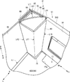
- FIG. 7 is a perspective view for explaining the assembly process of the stacking tray 1.
- FIG. 8 is an enlarged perspective view showing the support 35A and the like.
- 9 is a cross-sectional view taken along the line IX-IX in FIG.
- FIG. 10 is an enlarged perspective view showing the engagement piece 24 and the like.
- the stacking tray 1 is assembled by appropriately bending the connected first to third blanks 1A, 1B, 1C. As shown in FIG. 7, the operator bends the pair of left and right outer end walls 30 upward along the lower ruled line L10.
- the end wall body 11 (outer end wall 30) is bent at a substantially right angle with respect to the bottom wall body 10, and is provided in a standing posture on the peripheral edge (short side) of the bottom wall body 10.
- the operator bends the four outer edge walls 31 located at the four corners of the bottom wall body 10 inward (on the bottom wall body 10 side) along the side ruled line L11. Then, the outer edge wall 31 is bent at a substantially right angle with respect to the outer end wall 30 and is provided in a state extending from the side end portion of the outer end wall 30 toward the side wall body 12. In conjunction with the bending of the outer edge wall 31, the inner edge wall 36 is bent at a substantially right angle with respect to the support wall 35 along the second folding line L ⁇ b> 16, and from the side end of the support wall 35 toward the side wall body 12. It is provided in an extended state.
- the outer extension portion 37A and the inner extension portion 37B are provided in a state of extending toward the side wall body 12 in a posture that stands substantially vertically on the first ruled line L1. .
- the extension part 37 which opposes the left-right direction is extended to the position which a mutual mutual tip does not contact and overlaps with the engagement recessed part 25.
- FIG. since the inclined portions 20A are formed at the left and right end portions of the outer plate portion 20, it is possible to suppress the outer edge wall 31 and the like from being caught by the end portions of the outer plate portion 20 during the bending operation of the outer edge wall 31 and the like. it can. Thereby, the bending operation
- the support wall 35 is not bonded to the outer end wall 30 or the like. (See the broken thick arrow in FIG. 8), the first and second folding lines L15 and L16 are bent. In other words, the support wall 35 is bent at the first folding line L15 by causing the inner edge wall 36 to be folded at the second folding line L16, and the third folding line L17 is bent inward while being pushed inward.
- a column 35A having a cross section is formed.
- a surface of the support wall 35 between the second fold line L16 and the third fold line L17 is bent at a substantially right angle with respect to the inner edge wall 36, and is provided substantially parallel to the inner surface of the outer end wall 30.
- a surface of the support wall 35 between the first fold line L15 and the third fold line L17 is bent substantially at a right angle with respect to the inner end wall 34, and is provided substantially parallel to the inner surface of the outer edge wall 31.
- the support wall 35 (support 35 ⁇ / b> A) is provided so as to protrude in a substantially L shape from the corner formed by the outer end wall 30 and the outer edge wall 31 toward the inside of the stacking tray 1 when viewed from above. Yes. That is, the four support columns 35 ⁇ / b> A are formed in a rectangular tube shape at the four corners of the stacking tray 1. Each support 35 ⁇ / b> A extends upward from the upper surface of the bottom wall body 10. The upper end surface of each support wall 35 (support 35A) is lower than the uppermost end surface of the end wall body 11 (upper end surfaces of the outer end wall 30, the inner end wall 34, etc.) by the height of the second folding wall 33. Is provided.
- the operator bends the pair of front and rear outer plate portions 20 upward along the first ruled line L1.
- the outer plate portion 20 is bent at a substantially right angle with respect to the bottom wall body 10 and is provided in a state extending upward from the peripheral edge portion (long side) of the bottom wall body 10. In this state, the outer plate portion 20 overlaps the outer surface of each outer extension portion 37A.
- the operator bends the pair of front and rear upper plate edges 21 and the pair of front and rear inner plates 22 along the two second ruled lines L2 so as to wind the pair of left and right extension portions 37 from above.
- the upper plate edge portion 21 is disposed above the extension portion 37.
- the inner plate portion 22 is folded downward so as to cover the upper portion of each extension portion 37 with respect to the outer plate portion 20, and sandwiches each extension portion 37 with the outer plate portion 20.
- the engaging piece portions 24 connected to the left and right sides of the inner plate portion 22 hit the outer edge wall 31 and bend outward at the first engagement folding line L4 (see FIG. 10). ),
- the inner plate portion 22 and the like can be smoothly folded back.
- the arch convex portion 21B protrudes relatively higher than the upper plate edge portion 21 by bending the outer plate portion 20, the upper plate edge portion 21 and the inner plate portion 22 (see FIG. 1).
- the engaging convex portion 23 is bent at a substantially right angle with respect to the inner plate portion 22 and has a posture along the upper surface of the bottom wall body 10.
- the engaging convex portion 23 is fitted (engaged) with the engaging concave portion 25 in a posture along the bottom wall body 10 in a state in which the extended portions 37 are sandwiched between the outer plate portion 20 and the inner plate portion 22.
- the engagement convex portion 23 forms substantially the same plane as the upper surface of the bottom wall body 10 (upper bottom wall 10 ⁇ / b> B) in a state of being engaged with the engagement concave portion 25.
- the operator pushes the pair of left and right engaging pieces 24 of each inner plate portion 22 into the step between the lower end of the first folding wall 32 and the inner edge wall 36.
- the engagement piece 24 is bent along the first and second engagement folding lines L4 and L5 with the engagement protrusion 24A abutting against the cut piece 38A (see FIG. 8).
- the engaging protrusion 24A pushes the cut piece 38A into the support 35A and the engaging piece 24 is pushed in so as to fill the step between the lower end of the first folding wall 32 and the inner edge wall 36, the engaging protrusion 24A.
- Engages with the engaging groove 38 see FIG. 1).
- each of the end walls 11, the outer plate portion 20, and the inner plate portion 22 has a central shin 5 ⁇ / b> A extending in the vertical direction.
- the user stores contents such as products on the upper surface of the bottom wall body 10.
- the end openings 30A and 34A are formed on the left and right end faces, and the opening 13 is formed on both the front and rear side faces and the upper face, the internal contents are confirmed from the outer four sides of the stacking tray 1 (visually )can do. If it is not necessary to make the contents visible from the outside, the outer end opening 30A and the inner end opening 34A may be omitted.
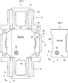
- FIG. 11 is a perspective view showing a state in which the stacking trays 1 are stacked.
- FIG. 12 is a perspective view for explaining the stacking action of the stacking tray 1.
- Stacking tray 1 can be stacked multiple times.
- the lower stacking tray 1 is also referred to as “lower tray 1 (D)”, and a symbol “(D)” is added to each component of the lower tray 1 (D), so that the upper stacking tray 1 1 is also referred to as “upper tray 1 (U)”, and a symbol “(U)” is added to each component of the upper tray 1 (U).
- the operator places the upper tray 1 (U) in the same direction above the lower tray 1 (D), and lowers the upper tray 1 (U).
- the operator causes the bottom wall 10 (U) of the upper tray 1 (U) to enter the opening 13 (D) of the lower tray 1 (D), and the four lower corners of the bottom wall 10 (U). Is placed on the upper end surfaces of the four columns 35A (D).
- the upper tray 1 (U) is stacked on the lower tray 1 (D).
- the engagement convex portion 23 is engaged with the bottom wall body 10 in a posture substantially parallel with the double-wall side wall 12 sandwiching the extension portion 37. It was set as the structure fitted to the recessed part 25 (refer FIG. 9). According to this configuration, when the extension portion 37 lifts the side wall body 12 by the force of tilting the end wall body 11 outward, the side wall body 12 is expanded (the state before the outer plate portion 20 and the inner plate portion 22 are bent). Thus, the tip of the engaging convex portion 23 abuts against the inner surface of the engaging concave portion 25 (the cross section of the missing portion 25A) because it rotates outward (rotates in the direction opposite to the thick arrow in FIG. 9).
- the engagement piece portion 24 is engaged with the engagement groove 38 in a state where the engagement projection 23 is fitted in the engagement recess 25, so that the inner It is possible to effectively inhibit the plate portion 22 from rotating in the developing direction.
- the state which the engagement convex part 23 fitted to the engagement recessed part 25 can be maintained, and the state which the side wall body 12 pinched
- the bottom wall 10 includes two corrugated sheets (lower bottom wall 10A and upper bottom wall 10B) in which the middle shin 5A is orthogonal (see FIG. 5). ). According to this configuration, it is possible to improve the bending rigidity, the torsional rigidity, and the like of the bottom wall body 10 as compared with the case where the lower bottom wall 10A and the upper bottom wall 10B are aligned in the same direction. . Thereby, even a heavy content can be appropriately accommodated.
- the bottom wall body 10 has a triple stacked structure in which the lower bottom wall 10A, the pair of intermediate bottom walls 10C, and the upper bottom wall 10B are stacked (see FIG. 9). Therefore, the rigidity and loading strength of the bottom wall body 10 can be further improved. Further, the end wall body 11 can be firmly connected to the bottom wall body 10 by sandwiching the intermediate bottom wall 10C between the lower bottom wall 10A and the upper bottom wall 10B.
- the end wall body 11 and the like have a double laminated structure, and the central shin 5A of the end wall body 11 extends in the vertical direction (see FIG. 4). According to this configuration, it is possible to improve the axial rigidity, compressive strength, and the like of the end wall body 11 as compared with the case where the center shin 5A of the end wall body 11 is extended in the lateral direction (direction orthogonal to the loading direction). Can do. Thereby, a plurality of stacking trays 1 containing heavy contents can be stacked.
- the inner edge wall 36 is bent at the second folding line L16 so that the support wall 35 is automatically turned along the first to third folding lines L15, L16, L17.
- the support 35A for supporting the upper stacking tray 1 (upper tray 1 (U)) can be easily formed in a short time.
- the end wall body 11 (the outer end wall 30 and the inner end wall 34) gradually increases from the lower side to the upper side when viewed from the toe surface side (left-right direction). Therefore, the opening 13 can be formed wider than the bottom wall 10. Accordingly, when the bottom wall body 10 (U) of the upper tray 1 (U) is caused to enter the opening 13 (D) of the lower tray 1 (D), the bottom wall body 10 (U) is moved to the lower tray 1 ( It is possible to prevent the end wall body 11 (D) of D) from being caught on the upper end portion or the like. Thereby, the upper tray 1 (U) can smoothly enter the lower tray 1 (D), and the stacking tray 1 can be easily stacked.
- the end surface (cut surface) of the inner edge wall 36 can be covered by folding the first folding wall 32 and overlapping the inner edge wall 36.
- the end surface (cut surface) of the outer edge wall 31 can be covered by folding the second folding wall 33 and overlapping the outer edge wall 31.
- FIG. 13 is a plan view showing the first and second blanks 2 ⁇ / b> A and 2 ⁇ / b> B of the stacking tray 2.
- FIG. 14 is a plan view showing the third blank 2 ⁇ / b> C of the stacking tray 2.
- FIG. 15 is a plan view showing a state in which the first blank 2A and the third blank 2C are connected.
- FIG. 16 is a cross-sectional view illustrating a connecting process (third process) of the stacking tray 2.
- the same components as those of the stacking tray 1 according to the first embodiment are denoted by the same reference numerals, and the same description is omitted.
- the stacking tray 2 is formed by connecting and assembling the first to third blanks 2A, 2B, and 2C shown in FIGS.
- Each of the first to third blanks 2A, 2B, 2C is formed by punching out a single sheet of cardboard sheet (double-sided cardboard) with a die cutter or the like.
- the first blank 2 ⁇ / b> A includes a lower bottom wall 10 ⁇ / b> A and a pair of side wall bodies 12.
- the first blank 2A is substantially the same as the first blank 1A of the first embodiment, but the size in the flow direction of the lower bottom wall 10A is slightly smaller than the size in the flow direction of the base end portion of the outer plate portion 20. It is short. For this reason, the flow direction both ends of 10 A of lower bottom walls are slightly dented in the flow direction inner side rather than a pair of side wall body 12 (outer plate part 20).
- the lower mark M1 is omitted.
- the second blank 2B includes an upper bottom wall 40B.
- a pair of cut lines L21 (cutting lines) along the outline of the missing portion 25A while leaving the inner side as a bottom wall folding line L20 (general ruled line or lead ruled line) on both sides in the flow direction of the upper bottom wall 40B. Is formed.
- the pair of cut lines L21 extends from the both ends in the step direction of the bottom wall folding line L20 so as to spread toward the flow direction end of the upper bottom wall 40B. That is, a range surrounded by the bottom wall folding line L20 and the pair of cut lines L21 (hereinafter also referred to as “defect folding part 41”) is formed in a substantially trapezoidal shape so as to constitute the missing part 25A. .
- Each of the pair of missing portions 25A is formed in a state in which the missing folded portion 41 (a part of the upper bottom wall 40B) is folded downward along the bottom wall folding line L20.
- two upper marks M4 are formed at the center in the step direction of the two bottom wall return lines L20.
- the third blank 2 ⁇ / b> C includes an intermediate bottom wall 40 ⁇ / b> C and an end wall body 11.
- a connecting convex part 42A and a connecting concave part 42B are formed side by side in the flow direction at one end (free end) in the step direction of the intermediate bottom wall 40C.
- the connecting convex portion 42A protrudes outward from the free end of the intermediate bottom wall 40C, and the connecting concave portion 42B is recessed inward from the free end of the intermediate bottom wall 40C.
- a pair of fitting grooves 43 are formed in the intermediate bottom wall 40C at positions sandwiched between the connecting convex portion 42A and the connecting concave portion 42B from both sides in the flow direction.
- Each fitting groove 43 is a notch extending inward from the free end of the intermediate bottom wall 40C.
- Each fitting groove 43 is formed so as to fit the broken folded portion 41 that is inverted along the bottom wall folded line L20 in the upper bottom wall 40B.
- the first and second intermediate marks M2, M3 are omitted.
- a contact portion 44 is connected to one end portion in the step direction of each outer edge wall 31 of the end wall body 11 (lower end portion in the assembled state) via a cut line L22 such as a sewing machine wire.
- Each of the pair of contact portions 44 is formed in a substantially triangular shape, and has an inclined side portion 44 ⁇ / b> A corresponding to the inclined portion 20 ⁇ / b> A of the outer plate portion 20.
- the inclined side portions 44A of the pair of contact portions 44 are inclined so as to be separated from each other toward the intermediate bottom wall 40C side from both ends in the flow direction of the lower ruled line L10.
- the inner end wall 34 is provided in a state of being connected to the other end in the step direction of the outer end wall 30 (upper end in the assembled state) via two third return lines L14.
- a third edge 34B is formed between the two third return lines L14.
- the worker forms the end wall body 11 by the same procedure as the first step of the connecting step already described.
- an operator performs a 2nd process.
- An operator applies a double-sided tape to the front liner 5B of the pair of intermediate bottom walls 40C, and arranges the pair of end wall bodies 11 on both sides in the flow direction of the lower bottom wall 10A on the work table.
- the inclination of the pair of front and rear contact portions 44 is inclined.
- the side portion 44A abuts against the inclined portion 20A of the pair of front and rear outer plate portions 20.
- each intermediate bottom wall 40C is positioned on the lower bottom wall 10A.
- the operator while bending each intermediate bottom wall 40C, the operator fits one connection convex portion 42A into the other connection concave portion 42B, and fits the other connection convex portion 42A into one connection concave portion 42B.
- the operator firmly presses each intermediate bottom wall 40C against the lower bottom wall 10A, whereby each intermediate bottom wall 40C is bonded to the lower bottom wall 10A via a double-sided tape (the second step is completed).
- each contact portion 44 is cut from the outer edge wall 31 along the cut line L22 and discarded.
- the fitting groove 43 of one intermediate bottom wall 40C and the fitting groove 43 of the other intermediate bottom wall 40C are connected to one.
- the worker executes the third step.
- the operator reverses the pair of broken folded portions 41 of the upper bottom wall 40B downward to form a missing portion 25A.
- the operator attaches a double-sided tape to the center of the lower surface of the upper bottom wall 40B and the lower surfaces of the pair of folded folded portions 41 that are folded back.
- the operator adheres the upper bottom wall 40B with the front liner 5B facing upward to the upper surfaces of the pair of intermediate bottom walls 40C.
- the operator aligns each upper mark M4 (see FIG. 13) of the upper bottom wall 40B with the center joint of the pair of intermediate bottom walls 40C, thereby allowing each intermediate bottom wall 40C and upper bottom wall 10B to Perform position alignment.
- the worker fits the pair of missing folded portions 41 folded back on the lower surface of the upper bottom wall 40B into a pair of fitting grooves 43 connected at the center of the pair of intermediate bottom walls 40C.
- the upper bottom wall 40B is bonded to each intermediate bottom wall 10C via the double-sided tape in a state where the pair of broken folded portions 41 are fitted in the pair of fitting grooves 43 (completion of the third step).
- the stacking tray 2 is assembled in substantially the same procedure as described above (see FIG. 1 and the like).
- the same effects as those of the stacking tray 1 according to the first embodiment can be obtained. Further, according to the stacking tray 2 according to the second embodiment, the intermediate bottom wall 40C with respect to the lower bottom wall 10A can be obtained simply by abutting the contact portion 44 of the end wall body 11 against the inclined portion 20A of the outer plate portion 20. Can be positioned easily and accurately.
- the missing folded portion 41 (a part of the upper bottom wall 40B) folded back at the bottom wall folding line L20 is fitted in the fitting groove 43 of the intermediate bottom wall 40C, the upper bottom wall 40B is connected to the intermediate bottom wall 40C. Can be easily and accurately aligned.
- the contact part 44 demonstrated above may be provided in the outer edge wall 31 of the stacking tray 1 which concerns on 1st Embodiment.
- the contact portion 44 may be omitted, and the intermediate bottom wall 40C may be positioned by the lower mark M1 formed on the lower bottom wall 10A.
- the upper bottom walls 10B and 40B and the intermediate bottom walls 10C and 40C are aligned in the same direction, but the present invention is not limited to this. , They may be orthogonal (crossed) to each other. Moreover, although the middle shin 5A of the lower bottom wall 10A and the upper bottom walls 10B and 40B (intermediate bottom walls 10C and 40C) is orthogonal to each other, the present invention is not limited to this. Good.
- the pair of intermediate bottom walls 10C are sandwiched between the lower bottom wall 10A and the upper bottom wall 10B, but the present invention is limited to this. Not.
- the pair of intermediate bottom walls 10C may be bonded to the lower surface of the lower bottom wall 10A.
- the outer extension portion 37A and the inner extension portion 37B are bonded together, and the present invention is not limited to this.
- any one of the outer extension 37A and the inner extension 37B may be omitted.
- the engagement piece portion 24 is engaged with the end wall body 11 and assists the suppression of the expansion of the side wall body 12. It is not limited to this.
- the side wall body 12 can effectively maintain the state in which the extension portion 37 is sandwiched only by fitting the engagement convex portion 23 and the engagement concave portion 25, the engagement piece portion 24, the engagement groove 38, and the like are provided. It may be omitted.
- the bottom wall body 10 is formed in a triple laminated structure and the end wall body 11 is formed in a double laminated structure. It is not limited to this.
- the bottom wall body 50 may be formed of two cardboard sheets and the end wall body 51 may be formed of one cardboard sheet.
- FIG. 17 is a plan view showing the first and second blanks 3 ⁇ / b> A and 3 ⁇ / b> B of the stacking tray 3.
- the same components as those of the stacking tray 1 according to the first embodiment are denoted by the same reference numerals, and the same description is omitted.
- the first blank 3A includes a lower bottom wall 50A, a pair of end wall bodies 51, and a pair of side wall bodies 12, and the second blank 3B includes an upper bottom wall 50B.
- the intermediate bottom wall 10 ⁇ / b> C, the outer end wall 30, the outer edge wall 31, the first and second folding walls 32 and 33, etc., which are the configuration of the stacking tray 1 according to the first embodiment, are omitted.
- Each end wall 51 includes an inner end wall 34, a support wall 35, an inner edge wall 36, an inner extension 37B, and the like.
- the middle shin 5A of the first blank 3A extends in a direction parallel to the long side of the lower bottom wall 50A.
- the middle shin 5A of the second blank 3B extends in a direction parallel to the short side of the upper bottom wall 50B.
- the operator bonds the upper bottom wall 50B to the upper surface of the lower bottom wall 50A to form the bottom wall body 50 having a double laminated structure, and stands the end wall body 51 and the side wall body 12 around the bottom wall body 50.
- the stacking tray 3 can be assembled by raising it.
- the middle shin 5A of the lower bottom wall 50A and the upper bottom wall 50B may intersect at an angle other than 90 degrees.
- the upper bottom wall 50B may be omitted, and the bottom wall body 50 may be formed of only the lower bottom wall 50A (not shown).
- the lower bottom wall 50A, the pair of side wall bodies 12 and the pair are formed using a single double-sided cardboard sheet (one-sided cardboard in which a liner is pasted on one side of the intermediate core 5A).
- the end wall body 51 is preferably formed.
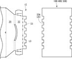
- the engagement concave portion 25 is formed in the lower bottom wall 50A and the engagement convex portion 23 is formed in the side wall body 12 (inner plate portion 22) by partially removing the single-sided cardboard. .
- the engaging convex portion 23 is formed in a substantially trapezoidal shape that becomes narrower from the proximal end toward the distal end.
- the engaging recess 25 is formed in a substantially trapezoidal shape that becomes narrower inward from the end (edge) of the bottom wall body 10, 50, but the present invention is not limited to this.
- the engaging convex portion 23 is formed in a substantially trapezoidal shape that becomes wider from the base end toward the distal end, and the engaging concave portion 25 is formed inward from the end portions of the bottom wall bodies 10 and 50.
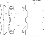
- the engaging convex portion 23 and the engaging concave portion 25 may be formed in an uneven shape (comb shape) (second modified example).
- the engaging protrusions 23 and the like may be formed in a triangular shape, a rectangular shape, a semicircular shape, or the like (not shown).
- the engaging convex portion 23 and the engaging concave portion 25 are formed long in the left-right direction, but the present invention is not limited to this.
- the present invention is not limited to this.
- FIG. 19A even if the engaging convex portion 23 is formed in the center portion in the left-right direction of the inner plate portion 22, and the engaging recess portion 25 is formed in the center portion in the left-right direction of the bottom wall bodies 10 and 50.
- Good third modification.
- a plurality of (for example, two in FIG. 19B) engagement protrusions 23 and engagement recesses 25 are formed at predetermined intervals (discretely) in the left-right direction. (4th modification).
- FIG. 20 is a perspective view showing the stacking tray 4.
- FIG. 21 is a plan view showing the first and second blanks 4A and 4B of the stacking tray 4.
- FIG. FIG. 22 is a plan view showing the third blank 4 ⁇ / b> C of the stacking tray 4.
- the same or corresponding components as those in the stacking tray 1 according to the first embodiment are denoted by the same reference numerals, and the same description is omitted.
- the stacking tray 4 according to the fourth embodiment has a closed rear surface and has an opening 63 continuous from the front surface to the upper surface. is doing.
- the stacking tray 4 includes an end piece body 66 provided in a state of being connected to a peripheral edge portion of the bottom wall body 60 on which the end wall body 61 is disposed, and a stacking protrusion portion protruding from the upper end surface of each column 81A. 88, which is different from the stacking tray 1 according to the first embodiment (details will be described later).
- the bottom wall body 60 is formed of two corrugated cardboard sheets (double laminated structure) (details will be described later).
- the stacking tray 4 is formed by connecting and assembling the first to third blanks 4A, 4B, and 4C shown in FIGS.
- Each of the first to third blanks 4A, 4B, 4C is formed by punching out a single sheet of cardboard sheet (double-sided cardboard) with a die cutter or the like.
- the first blank 4 ⁇ / b> A includes a lower bottom wall 60 ⁇ / b> A, a side wall body 12, a back wall 65, and a pair of end piece bodies 66.
- the side wall body 12 and the back wall 65 are provided in a state of being connected to both end portions in the step direction of the lower bottom wall 60A via the first ruled line L1.
- the pair of end piece bodies 66 are provided in a state of being connected to both ends in the flow direction of the lower bottom wall 60A via the third ruled line L30.
- the side wall body 12 is different in shape from the side wall body 12 in the first embodiment, and the curved hole 21A, the engagement piece portion 24, and the like are omitted, but the basic function of the side wall body 12 is the first function. Since it is the same as the side wall body 12 in embodiment, the description etc. are abbreviate
- the lower bottom wall 60A is formed in a substantially rectangular shape that is long in the flow direction.
- a lower mark M1 is formed at the center in the flow direction and at the end in the step direction on the back wall 65 side.
- Four laminated holes 67 are formed near the four corners of the lower bottom wall 60A.
- Each laminated hole 67 is a slit formed so as to form an angle of about 45 degrees with respect to the first ruled line L1 and the third ruled line L30. That is, the vicinity of the four corners of the lower bottom wall 60 ⁇ / b> A is partitioned into right-angled isosceles triangular regions by the laminated holes 67.
- the back wall 65 is formed in a substantially rectangular shape that is long in the flow direction.
- the dimension in the flow direction of the back wall 65 is set to be approximately the same as the dimension in the flow direction of the lower bottom wall 60A.
- the dimension of the back wall 65 in the step direction is set to be substantially the same as the height of the column 81A.
- Six sticking marks M5 are formed on both sides of the back wall 65 in the flow direction.
- the end piece body 66 includes an outer piece portion 70, a frame portion 71, an inner piece portion 72, and a second engagement convex portion 73.
- the outer piece 70 is provided in a state of being connected to one end in the flow direction of the lower bottom wall 60A via the third ruled line L30.
- the inner piece portion 72 is provided in a state of being connected to the distal end portion of the outer piece portion 70 via two frame folding curves L31.
- the frame portion 71 is formed between two frame folding curves L31.
- the second engaging convex portion 73 is provided in a state of being connected to the tip end portion of the inner piece portion 72 via the second fitting folding line L32.
- the third ruled line L30 is a general ruled line, and the frame folding curve L31 and the second fitting folding curve L32 are lead rules.
- the outer piece 70 is formed in a substantially rectangular shape that is long in the step direction.
- the stepwise dimension of the outer piece 70 is set to be substantially the same as the stepwise dimension of the lower bottom wall 60A.
- the dimension (projection dimension) in the flow direction of the outer piece 70 is set to be approximately the same as the dimension of the outer plate 20 of the side wall body 12.
- a second extension portion 74 is provided at an end portion (side end portion) on the side wall body 12 side of the outer piece portion 70 so as to be connected via an extended folding line L33 (general ruled line).
- the second extension 74 is formed in a substantially rectangular shape that is long in the step direction, and extends to the outside in the step direction with respect to the extension line of the second ruled line L2.
- the frame portion 71 is provided in a state of being connected to the middle of the outer piece portion 70 in the step direction via a frame folding curve L31.
- the frame portion 71 is formed in a substantially rectangular shape that is long in the step direction, and the outer piece portion 70 and the inner piece portion 72 are continued.
- the size of the frame portion 71 in the step direction is set to a length that is about half the size of the outer piece portion 70 in the step direction.
- the projecting dimension of the frame portion 71 is set slightly longer than the thickness of the cardboard sheet.
- the inner piece portion 72 and the second engagement convex portion 73 are formed in a substantially rectangular shape having substantially the same dimensions as the frame portion 71 in the flow direction.
- the protruding dimension of the inner piece portion 72 is set shorter than the protruding dimension of the outer piece portion 70 by the thickness of about one cardboard sheet.
- the projecting dimension of the second engaging convex part 73 is set shorter (for example, about half) than the projecting dimension of the inner piece part 72.
- the protrusion dimension of the 2nd engagement convex part 73 may be substantially the same as the protrusion dimension of the inner piece part 72, and may be slightly long.
- the second blank 4B includes an upper bottom wall 60B.
- the upper bottom wall 60B is slightly smaller than the lower bottom wall 60A and is formed in a substantially rectangular shape that is long in the step direction.
- the dimension in the flow direction of the upper bottom wall 60B is set to be equal to or less than the value obtained by subtracting the projecting dimension of the engagement convex portion 23 from the dimension in the step direction of the lower bottom wall 60A.
- a substantially semicircular finger-hanging recess 75A is formed in the center of the step direction at one end in the flow direction of the upper bottom wall 60B (front end in the assembled state).
- An upper mark M6 (cut line) is formed at the center in the step direction at the other end in the flow direction of the upper bottom wall 60B (the rear end in the assembled state).
- Four pillar notches 76 are cut out in a substantially rectangular shape at the four corners of the upper bottom wall 60B so as to correspond to the four columns 81A.
- the two column notches 76 located on both sides in the step direction with the finger hanging recess 75 ⁇ / b> A interposed therebetween are formed smaller than the other two column notches 76.
- the two relatively small column-shaped notches 76 are cut shallower than the other two column-shaped notches 76 by the protruding dimension of the engaging convex portion 23.
- a pair of second deficient portions 77A are formed at both ends in the step direction of the upper bottom wall 60B so as to be recessed inward.
- the second missing portion 77A is formed to have substantially the same shape (complementary shape) as the second engaging convex portion 73.
- a substantially semicircular finger-hanging recess 77B is formed in a recessed state at the center in the flow direction of the edge of the second defect 77A.
- the third blank 4 ⁇ / b> C includes an end wall body 61.
- two third blanks 4 ⁇ / b> C having a symmetrical shape are used, and a pair of left and right end wall bodies 61 are formed. Since the two third blanks 4C (the pair of end wall bodies 61) have a shape that matches when they are reversed, one third blank 4C (FIG. 22 shows the left end wall body 61) will be described below. To do.
- the end wall body 61 includes an outer end wall 30, an outer edge wall 31, a passage piece 80, an inner end wall 34, and a pair of support walls 81.
- the outer end wall 30 has a substantially rectangular outer shape that is long in the flow direction.
- the outer edge wall 31 is provided in a state of being connected to one end portion (side end portion (front end portion in the assembled state)) of the outer end wall 30 in the flow direction via a side ruled line L11.
- a substantially rectangular extension 82 is integrally formed below the outer edge wall 31 in the assembled state.
- the extension portion 82 is provided in a state extending outward from the distal end portion of the outer edge wall 31. For this reason, the extension part 82 and the outer edge wall 31 are formed in a substantially L shape as a whole.
- An extension fold line L40 for folding the extension portion 82 substantially in half is formed at an intermediate portion of the extension portion 82.
- the extended folding line L40 is a half-cut line cut about half in the thickness direction from the front liner 5B side, or a sewing line in which a plurality of cut lines are arranged at a predetermined interval.
- the passage piece 80 is provided in a state of being connected to the other end portion in the flow direction of the outer end wall 30 (the rear end portion in the assembled state) via the side ruled line L11.
- the passage piece 80 is formed in a rectangular shape elongated in the step direction, and a passage mark M7 is formed at the center of the passage piece 80 in the step direction.
- the inner end wall 34 is provided in a state of being connected to the stepwise end portion (upper end portion in the assembled state) of the outer end wall 30 via two third return lines L14.
- a third edge 34B is formed between the two third return lines L14.
- the pair of support walls 81 are provided in a state of being connected to both ends in the flow direction of the inner end wall 34 via the first folding line L15.
- the outer end wall 30 (inner end wall 34) is formed in a substantially trapezoidal shape that becomes gradually wider from the lower side to the upper side.
- the outer end wall 30 and the like are on the lower side. It is formed in a rectangular shape having substantially the same width from the top to the top.
- the side ruled lines L11, the first folding line L15, and the like are inclined with respect to the middle shin 5A.
- the side ruled lines L11 and the like are formed substantially parallel to the middle shin 5A. ing.
- outer end wall 30 and the side ruled lines L11 and the like are slightly different from those of the first embodiment, but their basic functions are the outer end wall 30 and the side ruled lines L11 in the first embodiment. And the like are omitted here.
- the outer end wall 30 and the side ruled lines L11 according to the fourth embodiment may have the same shape as the outer end wall 30 and the side ruled lines L11 according to the first embodiment.
- Each support wall 81 is formed in a substantially rectangular shape that is long in the step direction as a whole.
- the dimension in the step direction of each support wall 81 is set to be substantially the same as the dimension in the step direction of the inner end wall 34.
- the dimension (protrusion dimension) in the flow direction of each support wall 81 is set longer than the dimension in the flow direction of the inner end wall 34.
- a pair of support wall 81 is symmetrically formed in the flow direction on both sides of the inner end wall 34, only one support wall 81 will be described below.
- the support wall 81 includes a main body wall 83, a contact wall 84, a fixed wall 85, and a diagonal wall 86.
- the main body wall 83 is provided in a state of being connected to the inner end wall 34 via the first folding line L15, and has a second folding line L41 extending in parallel with the first folding line L15.
- the contact wall 84 is provided in a state of being connected to the main body wall 83 via the third folding line L42.
- the fixed wall 85 is provided in a state of being connected to the contact wall 84 via the fourth folding line L43.
- the diagonal wall 86 is provided in a state of being connected to the fixed wall 85 via the fifth folding line L44.
- the first to fifth folding lines L15, L41 to L44 are formed in parallel to each other and at substantially equal intervals.
- the first folding line L15 is a lead rule
- the second to fifth folding lines L41 to L44 are general-purpose ruled lines.
- the diagonal wall 86 is formed in a substantially rectangular shape wider in the flow direction than the contact wall 84 and the fixed wall 85. Although details will be described later, the diagonal wall 86 is formed to have substantially the same width as the diagonal of the quadrangular columnar column 81A. Both ends of the diagonal wall 86 in the step direction are curved so as to protrude toward the outer end wall 30 (upward in the assembled state).
- a curved recess 87 is formed at the lower end of the diagonal wall 86 in the assembled state, and a laminated layer protruding upward from the main body wall 83 (the contact wall 84 and the fixed wall 85) at the upper end of the diagonal wall 86 in the assembled state.
- a protrusion 88 is formed. The amount of protrusion of the laminated protrusion 88 is substantially the same as the amount of depression of the curved recess 87.
- FIG. 23 is a perspective view showing a state in which the connecting process of the stacking tray 4 is completed.
- FIG. 24 is an enlarged perspective view showing the support wall 82 and the like.
- an operator forms the end wall body 61 from the 3rd blank 4C (1st process).
- the operator attaches a double-sided tape (not shown) to the inner end wall 34 (around the inner end opening 34A), and attaches the inner end wall 34 (third edge 34B) to the two third return lines L14.
- a double-sided tape not shown
- the inner end wall 34 is overlapped on the inner surface (back liner 5C) of the outer end wall 30 and is bonded to the inner surface of the outer end wall 30 via a double-sided tape.
- the worker applies a double-sided tape to the front liner 5B of the fixed wall 85 (or along the side ruled line L11 of the outer end wall 30). Subsequently, the worker bends the support wall 81 so as to be involved (see FIGS. 23 and 24). Specifically, the operator folds the diagonal wall 86 inward along the fifth fold line L44 and folds the contact wall 84 inward along the third fold line L42. Then, the fixed wall 85 is bonded to the inner surface of the outer end wall 30 via the double-sided tape, and the diagonal wall 86 is sandwiched between the main body wall 83 and the contact wall 84 and the like. The support wall 81 is folded at the third folding line L42 and the fifth folding line L44 (see FIGS. 23 and 24).
- the operator attaches a double-sided tape to the distal end side (or proximal end side) of the extension portion 82, and folds the distal end side of the extension portion 82 outward along the extension fold line L40 (see FIG. 23).
- the distal end side of the extension portion 82 is bonded to the proximal end side through a double-sided tape, thereby forming an extension portion 82 having a double laminated structure.
- the first step is completed, and the end wall body 61 in which two cardboard sheets are laminated is completed (see FIG. 23).
- the operator repeats the first step to form two end wall bodies 61 that are symmetrical.
- ⁇ Second step> the operator connects the first blank 4A and the end wall body 61 (second step).
- An operator affixes a double-sided tape to the back liner 5C of the passage piece 80 of each end wall body 61.
- the worker bonds the passage piece 80 of the pair of end wall bodies 61 to the front liner 5B of the back wall 65 of the first blank 4A (see FIG. 24).
- the pair of passage pieces 80 are bonded to the left and right sides of the back wall 65 with their tips aligned with the sticking mark M5 (see FIG. 23).
- the second step is completed, and the pair of end wall bodies 61 are connected to the back wall 65 (see FIG. 23).
- ⁇ Third step> the operator connects the second blank 4B (upper bottom wall 60B) to the lower bottom wall 60A of the first blank 4A (third step).
- the operator attaches a double-sided tape to the back liner 5C of the upper bottom wall 60B (or the lower bottom wall 60A).
- the operator bonds the upper bottom wall 60B to the lower bottom wall 60A in a state where the upper mark M6 of the upper bottom wall 60B is aligned with the lower mark M1 of the lower bottom wall 60A.
- the upper bottom wall 60B is bonded to the lower bottom wall 60A via a double-sided tape in a posture in which the pair of second defect portions 77A are directed to the pair of outer piece portions 70.
- the front end (front edge) of the upper bottom wall 60B is separated rearward from the side wall body 12 (first ruled line L1). Further, the four laminated holes 67 opened in the lower bottom wall 60A are located in the four column cutout portions 76 of the upper bottom wall 60B.
- the third step is completed, and the bottom wall body 60 having a double laminated structure in which the lower bottom wall 60A and the upper bottom wall 60B are laminated is formed.
- the middle shin 5A of the lower bottom wall 60A and the middle shin 5A of the upper bottom wall 60B extend in directions orthogonal to each other.
- the engagement recess 25 is configured in a range surrounded by the upper surface of the lower bottom wall 60A and the front end of the upper bottom wall 60B.
- a pair of second engaging recesses 77 is configured in a range surrounded by the upper surface of the lower bottom wall 60A and the pair of second missing portions 77A.
- the pair of second engaging recesses 77 are formed in a state of being recessed on both the left and right sides of the upper surface of the bottom wall body 10.
- the sticking position of the double-sided tape in the above connecting step may be changed as appropriate, and an adhesive may be used instead of the double-sided tape.
- FIG. 25 is a perspective view showing an assembling process of the end wall body 61 and the like.
- FIG. 26 is an enlarged perspective view showing the column 81A and the like.
- FIG. 27 is a perspective view for explaining the assembly process of the stacking tray 4. Here, a case where the worker performs the assembly process manually will be described.
- the stacking tray 4 is assembled by appropriately bending the connected first to third blanks 4A, 4B, 4C. As shown in FIG. 25, the worker bends the back wall 65 upward along the first ruled line L1 so that the back wall 65 stands up substantially vertically. Next, the operator bends the pair of left and right outer end walls 30 forward at a substantially right angle along the side ruled line L11.
- the end wall body 61 (outer end wall 30) is arranged in a standing posture on the peripheral edge (short side) of the bottom wall body 60.
- the contact wall 84 of the rear support wall 81 is pressed against the back wall 65 and bent at the fourth folding line L43, and the body wall 83 is It is pushed inward while being folded at the first folding line L15 and at the second folding line L41 (see the broken line arrow in FIG. 24).
- the support wall 81 has the main body wall 83 bent at the first folding line L15 and the second folding line L41, and the contact wall 84 is bent at the third folding line L42.
- a support 81A having a rectangular cross section is formed by being folded at a fourth folding line L43. Note that the column 81A is disposed in the column notch 76 of the upper bottom wall 60B.
- the contact wall 84 overlaps the inner surface of the back wall 65 in a state where the contact wall 84 is bent at the third folding line L42.
- the fixed wall 85 is fixed to the outer end wall 30 along the side ruled line L11 in a state where the contact wall 84 is bent in a third folding line L42.
- the main body wall 83 is bent in a substantially L shape at a second folding line L41.
- the diagonal wall 86 is disposed in a state where the diagonal wall 86 is bent at the fifth folding line L44 and extends toward the third folding line L42. That is, the diagonal wall 86 is disposed on the diagonal line of the rectangular cross section of the support column 81A. In this way, the support wall 81 is rolled in, so that a prismatic column 81A is formed.
- each support wall 81 (support 81 ⁇ / b> A) is substantially flush with the uppermost end surfaces of the end wall body 61 and the back wall 65. Further, the laminated protrusions 88 of the diagonal walls 86 protrude upward from the upper end surface of the support column 81A.
- the operator bends the pair of left and right outer pieces 70 upward along the third ruled line L30 at a substantially right angle.
- the outer piece 70 is provided in a state extending upward from the peripheral edge (short side) of the bottom wall body 60 and overlaps the outer surface of the end wall body 61 (outer end wall 30).
- the operator bends the pair of left and right frame portions 71 and the pair of left and right inner piece portions 72 along the two frame folding curves L31 so as to wrap around the lower portion of the end wall body 61.
- the frame portion 71 passes through the end openings 30A and 34A and is disposed above the lower edge of the end openings 30A and 34A.
- the inner piece portion 72 is folded downward with respect to the outer piece portion 70 and sandwiches the lower portion of the end wall body 61 between the inner piece portion 70 and the outer piece portion 70.
- the engaging recess 77 is fitted.
- the second engaging convex portion 73 is bent at a substantially right angle with respect to the inner piece portion 72 and assumes a posture along the upper surface of the bottom wall body 60.
- the second engaging convex portion 73 is fitted into the second engaging concave portion 77 in a posture along the bottom wall body 60 in a state where the lower portion of the end wall body 61 is sandwiched between the outer piece portion 70 and the inner piece portion 72.
- Engage (engage) The second engaging convex portion 73 forms substantially the same plane as the upper surface of the bottom wall body 60 (upper bottom wall 60B) in a state of being fitted to the second engaging concave portion 77.
- the operator bends the pair of left and right outer edge walls 31 inward along the side ruled line L11 at a substantially right angle.
- the outer edge wall 31 and the extension portion 82 are provided in a state extending from the side end portion of the outer end wall 30 toward the side wall body 12.
- the contact wall 84 of the front support wall 81 is pushed out by the outer edge wall 31 and bent at the fourth folding line L43, and the main body wall 83 is bent at the first folding line L15. And it pushes out inside while folding at the 2nd folding line L41.
- the front support wall 81 forms a support column 81A having a rectangular cross section.
- the diagonal wall 86 is disposed on a diagonal line of the rectangular cross section of the column 81A.
- the second extension portion 74 is provided so as to overlap the outer surface of the extension portion 82 and extend toward the side wall body 12.
- the operator bends the outer plate part 20 upward at a substantially right angle along the first ruled line L ⁇ b> 1, and the upper plate edge portion 21 and the inner plate portion 22 are two second pieces. Bend along the ruled line L2. Then, the second extension portion 74 is sandwiched between the outer plate portion 20 and the inner plate portion 22 together with the extension portion 82. Subsequently, the worker bends the engaging convex portion 23 along the fitting folding line L3 and fits the engaging convex portion 23 into the engaging concave portion 25 (see FIG. 9 and the like).
- the assembly operation of the stacking tray 4 is completed (see FIG. 20).
- the intermediate shin 5A such as the end wall body 61 extends in the vertical direction.
- the stacking action of the stacking tray 4 is substantially the same as the stacking action of the stacking tray 1 according to the first embodiment, and the bottom wall body 60 of the upper stacking tray 4 is mounted on the four columns 81A of the lower stacking tray 4.
- a plurality of stacking trays 4 are stacked.
- the four stacking protrusions 88 of the lower stacking tray 4 are inserted into the stacking holes 67 of the upper stacking tray 4 from below (not shown).
- the front end surface of the laminated protrusion 88 passes through the laminated hole 67 and comes into contact with the lower end surface of the curved recess 87 (not shown).
- the second engagement convex portion 73 is in a substantially parallel posture with the bottom wall body 60 with the lower portion of the end wall body 61 being sandwiched therebetween. It was set as the structure fitted to the recessed part 77 (refer FIG. 20). According to this configuration, when a force that tilts the end wall body 61 outward is applied, the end piece body 66 is rotated outward so that the end piece body 66 is deployed, and the tip of the second engagement convex portion 73 is second. It strikes against the inner surface of the engaging recess 77 (cross section of the second defect portion 77A).
- the second extension portion 74 is sandwiched between the extension portion 82 and the side wall body 12 having a double wall structure.
- the 2nd extension part 74 lifts the side wall body 12, and rotates outside so that the side wall body 12 is expand
- the front end of the engaging convex portion 73 abutting against the inner surface of the second engaging concave portion 77
- the front end of the engaging convex portion 23 abuts against the inner surface of the engaging concave portion 25.
- the stacking protrusion 88 protrudes upward from the upper end surface of the support column 81 ⁇ / b> A, and the stacking hole 67 opens to the bottom wall body 60.
- the stacking protrusions 88 of the lower stacking tray 4 are inserted into the stacking holes 67 of the upper stacking tray 4.
- the positional deviation in the direction can be suppressed.
- the laminated protrusion 88 is disposed inside the support column 81 ⁇ / b> A, the laminated protrusion 88 can be prevented from interfering with a product or the like placed on the bottom wall body 60.
- the second engagement convex portion 73 and the second engagement concave portion 77 are formed in a substantially square shape, but the present invention is not limited to this.
- the second engaging convex portion 73 and the second engaging concave portion 77 are substantially the same as the engaging convex portion 23 and the engaging concave portion 25 of the stacking trays 1 to 3 according to the first to third embodiments. It may be formed in a trapezoidal shape (see FIGS. 6 and 18A), may be formed in an uneven shape (see FIG. 18B), a triangular shape (not shown), or the like. Further, the size (length) and the number of the second engaging convex portions 73 and the second engaging concave portions 77 can be changed as appropriate (see FIGS. 19A and 19B).
- the lower portion of the end wall body 61 is sandwiched between the inner piece portion 72 and the outer piece portion 70, but the present invention is not limited to this.
- the inner piece portion 72 and the outer piece portion 70 may be formed so as to sandwich at least a part of the end wall body 61, for example, the entire end wall body 61.
- the second extension 74 is connected to the outer piece 70 of the end piece body 66.
- the second extension 74 is not limited to this, and the second extension 74 is omitted. May be.
- the outer piece 70 may be formed with the same width as the inner piece 72 and the like.
- the laminated protrusion 88 has a curved convex shape, but the present invention is not limited to this.
- the size and shape of the laminated protrusion 88 can be changed as appropriate.
- the four laminated protrusions 88 are formed.
- the present invention is not limited to this, and for example, a pair of laminated protrusions 88 may be formed on a pair of diagonal support walls 81.
- the laminated hole 67 only needs to be formed in accordance with the shape and number of laminated protrusions 88.
- the stacked protrusions 88 are arranged on the diagonal lines of the support columns 81A, but the present invention is not limited to this.
- the diagonal wall 86 may be omitted, and the laminated protrusion may protrude from the upper end of the main body wall 83 (not shown).
- the support wall 35 (the support column 35A) is formed with a laminated protrusion (not shown) that protrudes upward from the upper end portion, and the bottom wall body. 10 and 50 may have a stacking hole (not shown) into which the stacking protrusions of the lower stacking trays 1 to 3 are inserted when a plurality of stacking trays 1 to 3 are stacked.
- the stacked hole 67 is formed only in the lower bottom wall 60A, but the present invention is not limited to this.
- the pillar notch 76 may be omitted from the upper bottom wall 60B, and the laminated hole 67 may be formed in the lower bottom wall 60A and the upper bottom wall 60B.
- the engaging concave portion 25 (defect portion 25A) is formed to have substantially the same shape as the engaging convex portion 23. Is not limited to this.
- the engaging convex part 23 may be formed slightly smaller than the engaging concave part 25 (not shown). That is, the protrusion dimension of the engagement convex part 23 may be set shorter than the front-rear width (notch depth) of the engagement concave part 25 (deletion part 25A).
- the engaging convex portion 23 in a state where the engaging convex portion 23 is engaged (arranged) with the engaging concave portion 25, it is between the front end of the engaging convex portion 23 and the inner surface of the engaging concave portion 25 (cross section of the defective portion 25 ⁇ / b> A).
- a slight gap will be formed.
- the gap is preferably a gap that allows the front end of the engaging convex portion 23 to abut against the inner surface of the engaging concave portion 25 when the side wall body 12 is rotated so as to be unfolded.
- the second engagement convex portion 73 may be formed slightly smaller than the second engagement concave portion 77 (not shown). .
- the support walls 35 and 81 are continuous with the end wall bodies 11, 51 and 61.
- the present invention is not limited to this.
- the support walls 35 and 81 may be formed of separate members separated from the end wall bodies 11, 51 and 61. In this case, it is preferable that the support walls 35 and 81 are bent to form the square columnar columns 35A and 81A, and then the columns 35A and 81A are bonded to the end wall bodies 11, 51, 61 and the like.
- the four support columns 35A and 81A (four support walls 35 and 81) are formed, but the present invention is not limited to this.
- the number of columns 35A and 81A may be two.
- pillars 35A and 81A were formed in the square cylinder shape of a substantially rectangular cross section, this invention is not limited to this.
- it may be formed in a rectangular tube shape having a polygonal cross section of a triangle or pentagon or more, or may be formed in a cylindrical shape having a substantially circular (elliptical) cross section (not shown).
- the end wall bodies 11, 51, 61 are formed higher than the side wall body 12.
- the present invention is not limited to this. They may be formed at substantially the same height.
- the upper end surface of the column 35A is provided below the upper end surface of the inner end wall 34 and the like. It may be formed at substantially the same position as the upper end surface of the end wall 34 or the like.
- the upper end surface of the support column 81A is formed at substantially the same position as the upper end surface of the end wall body 61. It may be provided below the end face.
- the side edges (the side ruled line L11, the first folding line L15, etc.) between the outer end wall 30 and the inner end wall 34 are medium shin 5A (
- the angle is not limited to this.
- the angle may be appropriately changed according to the height of the end wall body 11 or the like. Good.
- the end wall body 11 (the outer end wall 30 and the inner end wall 34) is, for example, It may be formed in a rectangular shape having substantially the same width from the lower side to the upper side as viewed from the surface side, or a substantially trapezoidal shape in which the width gradually decreases from the lower side to the upper side.
- the side edge of the end wall body 61 of the stacking tray 4 according to the fourth embodiment may be inclined outward.
- the bottom wall bodies 10, 50, 60 are formed in a substantially rectangular shape, and the pair of end wall bodies 11, 51, 61 and the pair of side wall bodies 12 are used. Are arranged so as to be shifted from each other by approximately 90 degrees in the circumferential direction, but the present invention is not limited to this.
- the bottom wall bodies 10, 50, and 60 may be formed in a polygonal shape other than a rectangle, such as a triangle, a pentagon, or a hexagon, or a circle (ellipse) (not shown). Even in this case, it is preferable that the end wall bodies 11, 51, 61 and the side wall body 12 are arranged at the peripheral edge portions of the bottom wall bodies 10, 50, 60 so as to be adjacent to each other.
- stacking trays 1 to 4 according to the first to fourth embodiments are formed of paper double-sided cardboard, but not limited to this, single-sided cardboard, It may be formed of paper cardboard sheets such as double-sided cardboard and double-sided cardboard, cardboard, or various cardboard sheets made of resin.
Landscapes
- Engineering & Computer Science (AREA)
- Mechanical Engineering (AREA)
- Cartons (AREA)
- Stackable Containers (AREA)
Abstract
Le problème décrit par la présente invention est de fournir une boîte d'emballage qui maintient un état dans lequel des corps de paroi latérale maintiennent entre eux des parties d'extension. À cet effet, l'invention porte sur un plateau d'empilement (1) (boîte d'emballage) conçu de telle sorte qu'une pluralité de ceux-ci peuvent être empilés verticalement, lequel plateau d'empilement comprend: un corps de paroi inférieure (10) qui a une partie évidée de mise en prise formée sur une surface de celui-ci d'une manière en retrait; des corps de paroi d'extrémité (11) disposés verticalement au niveau d'une partie de bord du corps de paroi inférieure (10); et un corps de paroi latérale (12) disposé verticalement au niveau d'une partie de rebord du corps de paroi inférieure (10), adjacent aux corps de paroi d'extrémité (11). Chacun des corps de paroi d'extrémité (11) a des parois de support (35) qui sont disposées de façon à faire saillie vers les parties intérieure et d'extension qui sont disposées de façon à s'étendre vers les corps de paroi latérale (12). Chacun des corps de paroi latérale (12) a une partie de plaque externe (20) qui est disposée de façon à s'étendre vers le haut à partir de la partie de rebord correspondante du corps de paroi inférieure (10), une partie de plaque intérieure (22) qui est pliée vers le bas de façon à recouvrir une partie supérieure de chacune des parties d'extension et à prendre en sandwich les parties d'extension avec la partie de plaque externe (20), et une saillie de mise en prise (23) qui est disposée de façon à être continue avec une partie d'extrémité avant de la partie de plaque interne (22) et vient en prise avec la partie évidée de mise en prise le long du corps de paroi inférieure (10).
Priority Applications (2)
| Application Number | Priority Date | Filing Date | Title |
|---|---|---|---|
| JP2019514357A JP6796195B2 (ja) | 2017-04-25 | 2018-04-10 | 包装箱 |
| CN201880016185.1A CN110431082B (zh) | 2017-04-25 | 2018-04-10 | 包装箱 |
Applications Claiming Priority (2)
| Application Number | Priority Date | Filing Date | Title |
|---|---|---|---|
| JP2017086268 | 2017-04-25 | ||
| JP2017-086268 | 2017-04-25 |
Publications (1)
| Publication Number | Publication Date |
|---|---|
| WO2018198750A1 true WO2018198750A1 (fr) | 2018-11-01 |
Family
ID=63918285
Family Applications (1)
| Application Number | Title | Priority Date | Filing Date |
|---|---|---|---|
| PCT/JP2018/015013 Ceased WO2018198750A1 (fr) | 2017-04-25 | 2018-04-10 | Boîte d'emballage |
Country Status (3)
| Country | Link |
|---|---|
| JP (1) | JP6796195B2 (fr) |
| CN (1) | CN110431082B (fr) |
| WO (1) | WO2018198750A1 (fr) |
Cited By (1)
| Publication number | Priority date | Publication date | Assignee | Title |
|---|---|---|---|---|
| JP2023084961A (ja) * | 2021-12-08 | 2023-06-20 | 株式会社トーモク | 包装箱 |
Families Citing this family (1)
| Publication number | Priority date | Publication date | Assignee | Title |
|---|---|---|---|---|
| TWI805448B (zh) * | 2022-07-14 | 2023-06-11 | 沈伯諭 | 可固定物品之包裝結構 |
Citations (10)
| Publication number | Priority date | Publication date | Assignee | Title |
|---|---|---|---|---|
| GB821245A (en) * | 1955-05-24 | 1959-10-07 | Waldhof Zellstoff Fab | An open-topped basket for fruit, vegetables, vegetables, potatoes or the like |
| JPS4513328Y1 (fr) * | 1966-07-20 | 1970-06-08 | ||
| JPH0462614U (fr) * | 1990-10-11 | 1992-05-28 | ||
| JPH0449061Y2 (fr) * | 1987-12-15 | 1992-11-18 | ||
| JPH09301349A (ja) * | 1996-05-08 | 1997-11-25 | Sogo Insatsu Shiki Kk | 組立箱 |
| EP1489016A1 (fr) * | 2002-11-14 | 2004-12-22 | Videcart, S.A. | Caisse empilable pour produits perissables |
| JP2005153917A (ja) * | 2003-11-21 | 2005-06-16 | Rengo Co Ltd | 輸送用包装体 |
| EP2277785A1 (fr) * | 2009-07-15 | 2011-01-26 | SCA Verpackung + Display Vertriebsgesellschaft mbH | Emballage ainsi que procédé et découpe destinés à sa fabrication |
| US20150076096A1 (en) * | 2013-09-19 | 2015-03-19 | Innovative Packaging Designs L. P. | Display tray |
| JP5782577B1 (ja) * | 2014-03-14 | 2015-09-24 | レンゴー株式会社 | 包装箱および製函装置 |
Family Cites Families (4)
| Publication number | Priority date | Publication date | Assignee | Title |
|---|---|---|---|---|
| EP0573381B1 (fr) * | 1992-06-03 | 2000-09-20 | Videcart, S.A. | plateau en carton empilable |
| CL2010000779A1 (es) * | 2010-07-22 | 2011-02-18 | Compania Patentes Del Pacifico Spa | Envase contenedor autoensamblable, que comprende los siguientes elementos estructurales principales, un fondo, dos laterales longitudinales o mayores y dos laterales transversales o menores, ranuras y arpones flexibles resistentes a la traccion; y metodo de fabricacion de elementos estructurales de un envase contenedor autoensamblable. |
| JP5813702B2 (ja) * | 2012-12-12 | 2015-11-17 | 株式会社国盛化学 | コンテナ |
| JP2014231369A (ja) * | 2013-05-29 | 2014-12-11 | 株式会社リコー | 梱包装置 |
-
2018
- 2018-04-10 WO PCT/JP2018/015013 patent/WO2018198750A1/fr not_active Ceased
- 2018-04-10 JP JP2019514357A patent/JP6796195B2/ja active Active
- 2018-04-10 CN CN201880016185.1A patent/CN110431082B/zh not_active Expired - Fee Related
Patent Citations (10)
| Publication number | Priority date | Publication date | Assignee | Title |
|---|---|---|---|---|
| GB821245A (en) * | 1955-05-24 | 1959-10-07 | Waldhof Zellstoff Fab | An open-topped basket for fruit, vegetables, vegetables, potatoes or the like |
| JPS4513328Y1 (fr) * | 1966-07-20 | 1970-06-08 | ||
| JPH0449061Y2 (fr) * | 1987-12-15 | 1992-11-18 | ||
| JPH0462614U (fr) * | 1990-10-11 | 1992-05-28 | ||
| JPH09301349A (ja) * | 1996-05-08 | 1997-11-25 | Sogo Insatsu Shiki Kk | 組立箱 |
| EP1489016A1 (fr) * | 2002-11-14 | 2004-12-22 | Videcart, S.A. | Caisse empilable pour produits perissables |
| JP2005153917A (ja) * | 2003-11-21 | 2005-06-16 | Rengo Co Ltd | 輸送用包装体 |
| EP2277785A1 (fr) * | 2009-07-15 | 2011-01-26 | SCA Verpackung + Display Vertriebsgesellschaft mbH | Emballage ainsi que procédé et découpe destinés à sa fabrication |
| US20150076096A1 (en) * | 2013-09-19 | 2015-03-19 | Innovative Packaging Designs L. P. | Display tray |
| JP5782577B1 (ja) * | 2014-03-14 | 2015-09-24 | レンゴー株式会社 | 包装箱および製函装置 |
Cited By (2)
| Publication number | Priority date | Publication date | Assignee | Title |
|---|---|---|---|---|
| JP2023084961A (ja) * | 2021-12-08 | 2023-06-20 | 株式会社トーモク | 包装箱 |
| JP7737885B2 (ja) | 2021-12-08 | 2025-09-11 | 株式会社トーモク | 包装箱 |
Also Published As
| Publication number | Publication date |
|---|---|
| CN110431082A (zh) | 2019-11-08 |
| CN110431082B (zh) | 2020-11-10 |
| JPWO2018198750A1 (ja) | 2020-01-09 |
| JP6796195B2 (ja) | 2020-12-02 |
Similar Documents
| Publication | Publication Date | Title |
|---|---|---|
| JPS61242837A (ja) | 段ボ−ル容器及び製法 | |
| JP6503883B2 (ja) | 包装箱 | |
| US7473215B2 (en) | Shipping container and method of manufacturing same | |
| JP7189069B2 (ja) | 蓋体およびこれを備えた包装箱 | |
| WO2018198750A1 (fr) | Boîte d'emballage | |
| JP6907074B2 (ja) | 包装箱 | |
| JP7214480B2 (ja) | 包装箱および包装箱の折り畳み方法 | |
| JP7081988B2 (ja) | 包装箱 | |
| JP2002019770A (ja) | 包装用箱 | |
| JP3238109U (ja) | 仕切部材およびブランク | |
| JP6975026B2 (ja) | 折畳み式包装箱 | |
| JP3171869U (ja) | 紙箱用ブランク | |
| JP4035295B2 (ja) | 紙製折込み箱の一次組立品 | |
| JP6988685B2 (ja) | トレイ | |
| JP3243247U (ja) | 段ボール箱 | |
| JP2021075301A (ja) | 多角形仕切付き包装箱 | |
| JP5021590B2 (ja) | 包装ケース | |
| JP6676421B2 (ja) | 箱用シート | |
| JP2022061198A (ja) | 包装箱 | |
| JP7847019B2 (ja) | 包装箱 | |
| JP7218247B2 (ja) | 包装箱 | |
| JP7409183B2 (ja) | 包装箱の製造方法 | |
| JP3251715U (ja) | 包装用箱 | |
| JP7218248B2 (ja) | 包装箱 | |
| JP2024155304A (ja) | 包装容器 |
Legal Events
| Date | Code | Title | Description |
|---|---|---|---|
| 121 | Ep: the epo has been informed by wipo that ep was designated in this application |
Ref document number: 18790197 Country of ref document: EP Kind code of ref document: A1 |
|
| ENP | Entry into the national phase |
Ref document number: 2019514357 Country of ref document: JP Kind code of ref document: A |
|
| NENP | Non-entry into the national phase |
Ref country code: DE |
|
| 122 | Ep: pct application non-entry in european phase |
Ref document number: 18790197 Country of ref document: EP Kind code of ref document: A1 |