WO2018199134A1 - Ascenseur - Google Patents
Ascenseur Download PDFInfo
- Publication number
- WO2018199134A1 WO2018199134A1 PCT/JP2018/016743 JP2018016743W WO2018199134A1 WO 2018199134 A1 WO2018199134 A1 WO 2018199134A1 JP 2018016743 W JP2018016743 W JP 2018016743W WO 2018199134 A1 WO2018199134 A1 WO 2018199134A1
- Authority
- WO
- WIPO (PCT)
- Prior art keywords
- bracket
- pulley
- horizontal projection
- rope
- elevator
- Prior art date
- Legal status (The legal status is an assumption and is not a legal conclusion. Google has not performed a legal analysis and makes no representation as to the accuracy of the status listed.)
- Ceased
Links
Images


Classifications
-
- B—PERFORMING OPERATIONS; TRANSPORTING
- B66—HOISTING; LIFTING; HAULING
- B66B—ELEVATORS; ESCALATORS OR MOVING WALKWAYS
- B66B5/00—Applications of checking, fault-correcting, or safety devices in elevators
-
- B—PERFORMING OPERATIONS; TRANSPORTING
- B66—HOISTING; LIFTING; HAULING
- B66B—ELEVATORS; ESCALATORS OR MOVING WALKWAYS
- B66B11/00—Main component parts of lifts in, or associated with, buildings or other structures
-
- B—PERFORMING OPERATIONS; TRANSPORTING
- B66—HOISTING; LIFTING; HAULING
- B66B—ELEVATORS; ESCALATORS OR MOVING WALKWAYS
- B66B17/00—Hoistway equipment
- B66B17/12—Counterpoises
-
- B—PERFORMING OPERATIONS; TRANSPORTING
- B66—HOISTING; LIFTING; HAULING
- B66B—ELEVATORS; ESCALATORS OR MOVING WALKWAYS
- B66B5/00—Applications of checking, fault-correcting, or safety devices in elevators
- B66B5/0043—Devices enhancing safety during maintenance
- B66B5/005—Safety of maintenance personnel
-
- B—PERFORMING OPERATIONS; TRANSPORTING
- B66—HOISTING; LIFTING; HAULING
- B66B—ELEVATORS; ESCALATORS OR MOVING WALKWAYS
- B66B7/00—Other common features of elevators
- B66B7/06—Arrangements of ropes or cables
Definitions
- the present invention relates to an elevator.
- the most popular elevator is a traction type elevator.
- the hoisting machine drives the car and the balance weight device through the rope.
- a pulley may be provided in the elevator balancing weight device.
- it is required to cover the pulley with a cover or the like in order to prevent the operator's fingers from being caught.
- a pulley is provided in a groove between an upper frame portion 20 and a vertical frame portion 18 of a counterweight frame formed of channel steel (the publication FIG. 1). reference).
- the upper frame part 20 and the vertical frame part 18 can cover the side surface and the upper part of the pulley, it is possible to prevent an operator's finger or the like from being caught in the pulley.
- the rotation plane of the pulley is parallel to the longitudinal direction of the upper frame portion 20.
- the pulley thickness is smaller than the groove width of the upper frame portion 20 and the vertical frame portion 18, the pulley can be installed in the groove of the upper frame portion 20 and the vertical frame portion 18, and the upper frame portion 20 And the vertical frame 18 can be used as a safety cover.
- the “rotation plane” means a plane on which a locus (circle) drawn at the time of rotation at a point away from the rotation axis of the pulley is placed.
- the normal of the plane of rotation is parallel to the rotation axis of the pulley.
- One pulley has an infinite number of rotation planes, and these rotation planes are parallel to each other. Therefore, when examining the direction of the rotation plane of the pulley, one of the rotation planes may be considered.
- an object of the present invention is to provide an elevator that can prevent a worker's finger or the like from being caught in a pulley, and at the same time, can secure a necessary gap size between a counterweight device and another device. .
- an elevator includes a car that moves up and down a hoistway, a balance weight device that is connected to the car through a rope, and the car and the balance weight that are connected through the rope.
- An elevator including a hoist for driving the device, wherein the balance weight device is provided on an upper frame of the balance weight frame by means of a bracket, and a rotation plane is in a predetermined interval between the longitudinal direction of the upper frame.
- It is constituted by a pulley around which the rope is wound, and a plurality of plate-shaped partial covers separable in the vertical direction, and is a wrap-around prevention cover that is fixed to the bracket and covers the side surface of the pulley,
- a horizontal projection has a bent portion at a lateral end of each partial cover projecting outward from the horizontal projection of the bracket, and the horizontal projection of the bent portion is a horizontal projection of the bracket.
- a winding prevention cover adjacent to.
- the wrap-around prevention cover provided in the elevator according to the present invention covers the side surface of the pulley, and can prevent the operator's finger or the like from being caught in the pulley. Since there is a bent part near the bracket at the side edge of the wrap-around prevention cover, the amount of overhang that the wrap-up prevention cover protrudes outward from the bracket (particularly in the direction of the car) is reduced. A necessary clearance dimension can be ensured between the slip-in prevention cover and the car or other equipment, and a collision can be prevented.
- FIG. 3 is an enlarged schematic view of the pulley vicinity structure shown in FIG. 2. It is a top view of the counterweight apparatus shown in FIG. Fig. 3 schematically shows a state in which a wrap-around prevention cover is removed from the counterweight device shown in Fig. 2.
- FIG. 1 is a schematic view schematically showing an embodiment of the elevator of the present invention.
- the elevator 100 includes a hoistway 102, a car 104, a counterweight device 106, and a hoisting machine 110.
- the elevator 100 is a machine room-less elevator, and a hoisting machine 110 is installed in a hoistway.
- the car 104 and the counterweight device 106 are connected through a rope 108.
- the rope 108 is hung on the sheave of the hoisting machine 110, and the hoisting machine 110 drives the car 104 and the counterweight device 106 through the rope 108 to raise and lower the hoistway 102.
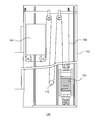
- FIG. 2 is a schematic view schematically showing the structure of the balance weight device of the elevator of the present invention.
- FIG. 2 includes a left front view and a right right side view.
- the counterweight device 106 includes a counterweight frame 202, a weight 204, a pulley 206, and an anti-roll-up cover 220.
- the counterweight frame 202 is mainly composed of two vertical frames 202a, an upper frame 202b, and a lower frame 202c.
- a plurality of weights 204 are placed inside the balance weight frame 202.
- the pulley 206 is provided on the upper frame 202b with a plurality of brackets, and the rope 108 is wound around the pulley 206.
- An entrainment prevention cover 220 is provided on the side surface of the pulley 206.
- FIG. 3 is an enlarged schematic view of the pulley vicinity structure shown in FIG. 4 is a plan view of the counterweight device shown in FIG.
- the car 104 and the nearest hoistway wall 102a are also shown in FIG.
- the rotation plane 400 of the pulley 206 is also indicated by a two-dot chain line.
- FIG. 5 schematically shows a state in which the anti-winding cover is removed from the counterweight device shown in FIG. Show.
- the rotation plane 400 of the pulley 206 has a predetermined angle ⁇ (0 ° ⁇ ⁇ 90 °) between the longitudinal direction of the upper frame 202b.
- the angle ⁇ is determined by the traveling direction and angle of the rope 108 to be set by the pulley 206.
- the pulley 206 is attached to the upper frame 202b by a plurality of brackets.
- the bracket includes a first bracket 212, a second bracket 214, a third bracket 215, a third bracket 216, and a fourth bracket 218.
- the first bracket 212 is a base plate, and is fixed to the upper frame 202b by an angle, a bolt, or the like.
- the second bracket 214 is channel steel and is fixed to the first bracket 212 with its opening facing upward.
- the plate-like third bracket 215 and the third bracket 216 are vertically fixed to the two groove walls of the second bracket 214, respectively.
- the pulley 206 is provided between the third bracket 215 and the third bracket 216, and the rotation axis thereof is supported by the third bracket 215 and the third bracket 216.
- the fourth bracket 218 is channel steel and connects the third bracket 215 and the third bracket 216 from above over the pulley 206.
- the fourth bracket 218 not only reinforces the support for the two third brackets, but can also prevent the operator's fingers and the like from being caught, and can also cover the dust falling on the pulley 206 as a cover.
- a rope detachment prevention plate 232 and a rope detachment prevention plate 234 are provided near the left and right edges of the pulley 206, respectively.
- the left and right edges of the pulley 206 are a part where the rope 108 enters the rope groove of the pulley 206 and a part where the rope 108 leaves the rope groove. At these portions, the rope 108 is easily detached from the rope groove of the pulley 206.
- a dustproof cover 236 and a dustproof cover 238 are provided at both left and right ends of the fourth bracket 218 in order to block dust falling on the pulley 206.
- the entrainment prevention cover 220 includes two partial covers that are separable in the vertical direction, that is, an upper cover 222 and a lower cover 224.
- the upper cover 222 and the lower cover 224 are plate-shaped.
- the upper cover 222 and the lower cover 224 are fixed to the third bracket 215 by bolts, and cover one side surface (side surface facing the car 104) of the pulley 206. This prevents an operator's finger or the like from being caught between the pulley 206 and the rope 108.
- the plate-shaped wrap-around prevention cover 220 has a simple structure and is low in cost.
- the other side surface of the pulley 206 faces the hoistway wall 102a, and the distance between the counterweight device 106 and the hoistway wall 102a is small, so that an operator can connect with the counterweight device 106. Since there is no work between the hoistway walls 102a, no wrapping prevention cover is provided on the side of the pulley 206 facing the hoistway walls 102a.
- the elevator car and the counterweight device move up and down in the hoistway. In order to prevent the two from colliding when moving up and down, it is necessary to leave a certain distance between the horizontal projections of the two.
- the horizontal projection has a bent portion 222a at the lateral end of the upper cover 222 protruding outward from the horizontal projection of the bracket described above, and the horizontal projection of the bent portion 222a. Is close to the horizontal projection of the bracket described above.
- FIG. 4 is a plan view, it represents a horizontal projection of each part of the elevator 100.
- the maximum contour of the horizontal projection of the brackets described above is mainly the first.
- the upper cover 222 is made of a plate material.
- the horizontal projection (see FIG. 4) of the right side edge of the upper cover 222 in FIG. 3 protrudes from the maximum outline of the horizontal projection of the bracket described above. Protruding ". If the upper cover 222 is a flat plate, the lateral end on the right side will extend in the direction indicated by the broken line in FIG. If it becomes so, the space
- a bent portion 222a is formed at the right end of the upper cover 222, and the horizontal projection of the bent portion 222a is close to the horizontal projection of the bracket described above. .
- the formation of the bent portion 222a moved the right side end of the upper cover 222 from the position indicated by the broken line to the position indicated by the solid line.
- the horizontal projection of the bent portion 222a slightly protrudes from the maximum contour of the bracket horizontal projection described above, the protruding amount of the upper cover 222 protruding in the direction of the car 104 is greatly reduced. As a result, a necessary gap can be ensured between the counterweight device 106 (upper cover 222) and the car 104, and collision can be prevented.
- the horizontal projection has a bent part 224a at the right side end of the lower cover 224 protruding outward from the horizontal projection of the bracket described above, and the horizontal projection of the bent part 224a is Close to the horizontal projection of the bracket described above.
- the bent portion 224 a of the lower cover 224 has the same effect as the bent portion 222 a of the upper cover 222. That is, the amount of overhang of the lower cover 224 protruding in the direction of the car 104 can be greatly reduced, and a necessary gap dimension can be secured between the counterweight device 106 (lower cover 224) and the car 104, Collisions can be prevented.
- the hoistway is narrow and the rotation plane of the pulley of the counterweight device has a predetermined angle ⁇ between the longitudinal direction of the upper frame, the required clearance dimension between the counterweight device and the car is required. It is possible to prevent the operator's fingers and the like from being caught in the pulley by installing the anti-rolling cover while securing the above.
- the wrapping prevention cover 220 is divided into the upper cover 222 and the lower cover 224 in the vertical direction, when the wrapping prevention cover 220 is attached, the interval between the wrapping prevention cover 220 and the pulley 206 can be easily adjusted. It can. Specifically, first, the lower cover 224 can be attached. At this time, since the interval between the bent portion 224a of the lower cover 224 and the pulley 206 can be directly seen from above the lower cover 224, the interval between the bent portion 224a and the pulley 206 can be easily set within an appropriate interval range. Can be adjusted. When the upper cover 222 is attached, the bent portion 222a of the upper cover 222 has substantially the same bending angle or the same curve as the bent portion 224a of the lower cover 224.
- the outer surface is adjusted to be substantially the same as the outer surface of the bent portion 224a of the lower cover 224, the inner surface of the bent portion 222a also approaches the inner surface of the bent portion 224a. Accordingly, the distance between the bent portion 222a of the upper cover 222 and the pulley 206 can be easily set to an appropriate distance range. Moreover, since the space
- winding prevention cover 220 is divided into the upper cover 222 and the lower cover 224 in the vertical direction, when checking the distance between the rope detachment prevention plate 232 and the pulley 206, and the distance between the rope detachment prevention plate 234 and the pulley 206. Can be confirmed and removed by simply removing the upper cover 222, and the inspection efficiency can be improved. In addition, when exchanging the rope 108, since it can replace
- the outer surface of the bent portion 224a of the lower cover 224 is adjusted to be substantially the same as the outer surface of the bent portion 222a of the upper cover 222, the bent portion 224a and the pulley 206
- the interval can be easily set to an appropriate interval range.
- the present invention is not limited to the above-described embodiments, and includes various modifications.
- the above-described embodiments have been described in detail for easy understanding of the present invention, and are not necessarily limited to those having all the configurations described.
- a part of the configuration of one embodiment can be replaced with the configuration of another embodiment, and the configuration of another embodiment can be added to the configuration of one embodiment.
Landscapes
- Engineering & Computer Science (AREA)
- Civil Engineering (AREA)
- Mechanical Engineering (AREA)
- Structural Engineering (AREA)
- Cage And Drive Apparatuses For Elevators (AREA)
- Lift-Guide Devices, And Elevator Ropes And Cables (AREA)
Abstract
La présente invention concerne un ascenseur comprenant une cabine d'ascenseur qui monte et descend dans une cage d'ascenseur, un dispositif de contrepoids relié à la cabine d'ascenseur au moyen d'un câble, et une machine de levage qui entraîne la cabine d'ascenseur et le dispositif de contrepoids au moyen du câble, l'ascenseur étant caractérisé en ce que le dispositif de contrepoids comporte : une poulie dans laquelle une surface rotative a un angle prescrit par rapport à la direction de la longueur d'un cadre supérieur, et autour de laquelle le câble est enroulé, la poulie étant disposée sur le cadre supérieur d'un cadre de contrepoids par l'intermédiaire d'un support ; et un couvercle de prévention de l'enchevêtrement qui est conçu à partir d'une pluralité de couvercles partiels séparables dans la direction verticale, est fixé au support, et recouvre une surface latérale de la poulie, le couvercle de prévention de l'enchevêtrement ayant une partie courbée au niveau d'une partie d'extrémité latérale aux couvercles partiels de telle sorte qu'une saillie horizontale fait saillie vers l'extérieur à partir d'une saillie horizontale du support, et étant telle que la saillie horizontale de la partie coudée est adjacente à la saillie horizontale du support.
Priority Applications (1)
| Application Number | Priority Date | Filing Date | Title |
|---|---|---|---|
| JP2019514560A JP6770183B2 (ja) | 2017-04-27 | 2018-04-25 | エレベータ |
Applications Claiming Priority (2)
| Application Number | Priority Date | Filing Date | Title |
|---|---|---|---|
| CN201710286574.3 | 2017-04-27 | ||
| CN201710286574.3A CN108792863B (zh) | 2017-04-27 | 2017-04-27 | 电梯 |
Publications (1)
| Publication Number | Publication Date |
|---|---|
| WO2018199134A1 true WO2018199134A1 (fr) | 2018-11-01 |
Family
ID=63920370
Family Applications (1)
| Application Number | Title | Priority Date | Filing Date |
|---|---|---|---|
| PCT/JP2018/016743 Ceased WO2018199134A1 (fr) | 2017-04-27 | 2018-04-25 | Ascenseur |
Country Status (3)
| Country | Link |
|---|---|
| JP (1) | JP6770183B2 (fr) |
| CN (1) | CN108792863B (fr) |
| WO (1) | WO2018199134A1 (fr) |
Cited By (1)
| Publication number | Priority date | Publication date | Assignee | Title |
|---|---|---|---|---|
| CN115744556A (zh) * | 2022-12-12 | 2023-03-07 | 浙江梅轮电梯股份有限公司 | 一种隐藏式轿底加重结构 |
Citations (5)
| Publication number | Priority date | Publication date | Assignee | Title |
|---|---|---|---|---|
| JPS6047781U (ja) * | 1984-05-16 | 1985-04-04 | 株式会社日立製作所 | エレベータ |
| EP1333000A1 (fr) * | 2002-02-05 | 2003-08-06 | Monitor S.p.A. | Ascenseur à poulie de traction sans salle de machines |
| JP2006027904A (ja) * | 2004-07-17 | 2006-02-02 | Inventio Ag | 平行に配置された平ベルト式懸架手段を有するエレベータ装置 |
| EP2781481A1 (fr) * | 2013-03-19 | 2014-09-24 | Kone Corporation | Agencement de contrepoids pour un ascenseur |
| CN204938688U (zh) * | 2015-07-24 | 2016-01-06 | 中奥电梯有限公司 | 一种对重轮组件 |
Family Cites Families (5)
| Publication number | Priority date | Publication date | Assignee | Title |
|---|---|---|---|---|
| TWI222954B (en) * | 2002-12-11 | 2004-11-01 | Yung Tay Engineering Co Ltd | Elevator system without a control room |
| JP2013049530A (ja) * | 2011-08-31 | 2013-03-14 | Toshiba Elevator Co Ltd | 連結金具およびそれを備えたカウンターウェイト |
| CN203855291U (zh) * | 2014-03-25 | 2014-10-01 | 西尼电梯(杭州)有限公司 | 电梯对重装置 |
| CN203922397U (zh) * | 2014-06-26 | 2014-11-05 | 浙江飞亚电梯有限公司 | 一种电梯对重装置 |
| CN204588414U (zh) * | 2015-01-14 | 2015-08-26 | 浙江诺比克电梯有限公司 | 一种电梯对重架 |
-
2017
- 2017-04-27 CN CN201710286574.3A patent/CN108792863B/zh active Active
-
2018
- 2018-04-25 WO PCT/JP2018/016743 patent/WO2018199134A1/fr not_active Ceased
- 2018-04-25 JP JP2019514560A patent/JP6770183B2/ja active Active
Patent Citations (5)
| Publication number | Priority date | Publication date | Assignee | Title |
|---|---|---|---|---|
| JPS6047781U (ja) * | 1984-05-16 | 1985-04-04 | 株式会社日立製作所 | エレベータ |
| EP1333000A1 (fr) * | 2002-02-05 | 2003-08-06 | Monitor S.p.A. | Ascenseur à poulie de traction sans salle de machines |
| JP2006027904A (ja) * | 2004-07-17 | 2006-02-02 | Inventio Ag | 平行に配置された平ベルト式懸架手段を有するエレベータ装置 |
| EP2781481A1 (fr) * | 2013-03-19 | 2014-09-24 | Kone Corporation | Agencement de contrepoids pour un ascenseur |
| CN204938688U (zh) * | 2015-07-24 | 2016-01-06 | 中奥电梯有限公司 | 一种对重轮组件 |
Cited By (1)
| Publication number | Priority date | Publication date | Assignee | Title |
|---|---|---|---|---|
| CN115744556A (zh) * | 2022-12-12 | 2023-03-07 | 浙江梅轮电梯股份有限公司 | 一种隐藏式轿底加重结构 |
Also Published As
| Publication number | Publication date |
|---|---|
| JP6770183B2 (ja) | 2020-10-14 |
| JPWO2018199134A1 (ja) | 2020-01-23 |
| CN108792863B (zh) | 2020-03-24 |
| CN108792863A (zh) | 2018-11-13 |
Similar Documents
| Publication | Publication Date | Title |
|---|---|---|
| US20110108366A1 (en) | Elevator apparatus | |
| EP1302430B1 (fr) | Dispositif d'ascenseur | |
| JP2009073658A (ja) | マシンルームレスエレベータ | |
| JP6738964B2 (ja) | エレベーター | |
| JP5805508B2 (ja) | エレベーター装置 | |
| WO2018199134A1 (fr) | Ascenseur | |
| JP2012046287A (ja) | エレベータ巻上げ機支持機構 | |
| JP5930813B2 (ja) | エレベータ装置及びその改修方法 | |
| JP6261418B2 (ja) | エレベータの釣合おもり装置及びその改修方法 | |
| JPWO2006033146A1 (ja) | エレベータ装置 | |
| JP2014189373A (ja) | 主ロープ取り替え用補助具 | |
| WO2011135648A1 (fr) | Dispositif de contrepoids pour ascenseur et ascenseur | |
| JP4752268B2 (ja) | エレベータ装置 | |
| JP4498759B2 (ja) | エレベータ装置 | |
| HK1259528A1 (zh) | 电梯 | |
| JP4841211B2 (ja) | エレベータの乗りかごドア駆動装置 | |
| JP6692461B2 (ja) | エレベータ装置 | |
| JP5570602B2 (ja) | エレベータ装置 | |
| WO2015049790A1 (fr) | Dispositif d'ascenseur | |
| JP2006256702A (ja) | エレベーター装置 | |
| JP6412232B1 (ja) | エレベータ装置 | |
| WO2016174710A1 (fr) | Dispositif d'ascenseur | |
| JP5681284B2 (ja) | エレベータ | |
| CN205892423U (zh) | 电梯装置 | |
| JP5473961B2 (ja) | エレベータの乗りかご |
Legal Events
| Date | Code | Title | Description |
|---|---|---|---|
| 121 | Ep: the epo has been informed by wipo that ep was designated in this application |
Ref document number: 18791154 Country of ref document: EP Kind code of ref document: A1 |
|
| ENP | Entry into the national phase |
Ref document number: 2019514560 Country of ref document: JP Kind code of ref document: A |
|
| NENP | Non-entry into the national phase |
Ref country code: DE |
|
| 122 | Ep: pct application non-entry in european phase |
Ref document number: 18791154 Country of ref document: EP Kind code of ref document: A1 |