WO2018199327A1 - Élément conducteur et son procédé de fabrication - Google Patents
Élément conducteur et son procédé de fabrication Download PDFInfo
- Publication number
- WO2018199327A1 WO2018199327A1 PCT/JP2018/017306 JP2018017306W WO2018199327A1 WO 2018199327 A1 WO2018199327 A1 WO 2018199327A1 JP 2018017306 W JP2018017306 W JP 2018017306W WO 2018199327 A1 WO2018199327 A1 WO 2018199327A1
- Authority
- WO
- WIPO (PCT)
- Prior art keywords
- conductive member
- substrate
- metal oxide
- film
- potential region
- Prior art date
- Legal status (The legal status is an assumption and is not a legal conclusion. Google has not performed a legal analysis and makes no representation as to the accuracy of the status listed.)
- Ceased
Links
Images

Classifications
-
- C—CHEMISTRY; METALLURGY
- C22—METALLURGY; FERROUS OR NON-FERROUS ALLOYS; TREATMENT OF ALLOYS OR NON-FERROUS METALS
- C22C—ALLOYS
- C22C38/00—Ferrous alloys, e.g. steel alloys
- C22C38/04—Ferrous alloys, e.g. steel alloys containing manganese
-
- C—CHEMISTRY; METALLURGY
- C22—METALLURGY; FERROUS OR NON-FERROUS ALLOYS; TREATMENT OF ALLOYS OR NON-FERROUS METALS
- C22C—ALLOYS
- C22C38/00—Ferrous alloys, e.g. steel alloys
- C22C38/18—Ferrous alloys, e.g. steel alloys containing chromium
- C22C38/40—Ferrous alloys, e.g. steel alloys containing chromium with nickel
- C22C38/44—Ferrous alloys, e.g. steel alloys containing chromium with nickel with molybdenum or tungsten
-
- H—ELECTRICITY
- H01—ELECTRIC ELEMENTS
- H01M—PROCESSES OR MEANS, e.g. BATTERIES, FOR THE DIRECT CONVERSION OF CHEMICAL ENERGY INTO ELECTRICAL ENERGY
- H01M8/00—Fuel cells; Manufacture thereof
- H01M8/02—Details
- H01M8/0202—Collectors; Separators, e.g. bipolar separators; Interconnectors
- H01M8/0204—Non-porous and characterised by the material
-
- H—ELECTRICITY
- H01—ELECTRIC ELEMENTS
- H01M—PROCESSES OR MEANS, e.g. BATTERIES, FOR THE DIRECT CONVERSION OF CHEMICAL ENERGY INTO ELECTRICAL ENERGY
- H01M8/00—Fuel cells; Manufacture thereof
- H01M8/02—Details
- H01M8/0202—Collectors; Separators, e.g. bipolar separators; Interconnectors
- H01M8/0204—Non-porous and characterised by the material
- H01M8/0206—Metals or alloys
-
- H—ELECTRICITY
- H01—ELECTRIC ELEMENTS
- H01M—PROCESSES OR MEANS, e.g. BATTERIES, FOR THE DIRECT CONVERSION OF CHEMICAL ENERGY INTO ELECTRICAL ENERGY
- H01M8/00—Fuel cells; Manufacture thereof
- H01M8/02—Details
- H01M8/0202—Collectors; Separators, e.g. bipolar separators; Interconnectors
- H01M8/0204—Non-porous and characterised by the material
- H01M8/0206—Metals or alloys
- H01M8/0208—Alloys
-
- H—ELECTRICITY
- H01—ELECTRIC ELEMENTS
- H01M—PROCESSES OR MEANS, e.g. BATTERIES, FOR THE DIRECT CONVERSION OF CHEMICAL ENERGY INTO ELECTRICAL ENERGY
- H01M8/00—Fuel cells; Manufacture thereof
- H01M8/02—Details
- H01M8/0202—Collectors; Separators, e.g. bipolar separators; Interconnectors
- H01M8/0204—Non-porous and characterised by the material
- H01M8/0206—Metals or alloys
- H01M8/0208—Alloys
- H01M8/021—Alloys based on iron
-
- H—ELECTRICITY
- H01—ELECTRIC ELEMENTS
- H01M—PROCESSES OR MEANS, e.g. BATTERIES, FOR THE DIRECT CONVERSION OF CHEMICAL ENERGY INTO ELECTRICAL ENERGY
- H01M8/00—Fuel cells; Manufacture thereof
- H01M8/02—Details
- H01M8/0202—Collectors; Separators, e.g. bipolar separators; Interconnectors
- H01M8/0204—Non-porous and characterised by the material
- H01M8/0215—Glass; Ceramic materials
-
- H—ELECTRICITY
- H01—ELECTRIC ELEMENTS
- H01M—PROCESSES OR MEANS, e.g. BATTERIES, FOR THE DIRECT CONVERSION OF CHEMICAL ENERGY INTO ELECTRICAL ENERGY
- H01M8/00—Fuel cells; Manufacture thereof
- H01M8/02—Details
- H01M8/0202—Collectors; Separators, e.g. bipolar separators; Interconnectors
- H01M8/0204—Non-porous and characterised by the material
- H01M8/0223—Composites
- H01M8/0228—Composites in the form of layered or coated products
-
- H—ELECTRICITY
- H01—ELECTRIC ELEMENTS
- H01M—PROCESSES OR MEANS, e.g. BATTERIES, FOR THE DIRECT CONVERSION OF CHEMICAL ENERGY INTO ELECTRICAL ENERGY
- H01M8/00—Fuel cells; Manufacture thereof
- H01M8/02—Details
- H01M8/0202—Collectors; Separators, e.g. bipolar separators; Interconnectors
- H01M8/0247—Collectors; Separators, e.g. bipolar separators; Interconnectors characterised by the form
- H01M8/0254—Collectors; Separators, e.g. bipolar separators; Interconnectors characterised by the form corrugated or undulated
-
- H—ELECTRICITY
- H01—ELECTRIC ELEMENTS
- H01M—PROCESSES OR MEANS, e.g. BATTERIES, FOR THE DIRECT CONVERSION OF CHEMICAL ENERGY INTO ELECTRICAL ENERGY
- H01M8/00—Fuel cells; Manufacture thereof
- H01M8/02—Details
- H01M8/0202—Collectors; Separators, e.g. bipolar separators; Interconnectors
- H01M8/0258—Collectors; Separators, e.g. bipolar separators; Interconnectors characterised by the configuration of channels, e.g. by the flow field of the reactant or coolant
- H01M8/026—Collectors; Separators, e.g. bipolar separators; Interconnectors characterised by the configuration of channels, e.g. by the flow field of the reactant or coolant characterised by grooves, e.g. their pitch or depth
-
- H—ELECTRICITY
- H01—ELECTRIC ELEMENTS
- H01M—PROCESSES OR MEANS, e.g. BATTERIES, FOR THE DIRECT CONVERSION OF CHEMICAL ENERGY INTO ELECTRICAL ENERGY
- H01M8/00—Fuel cells; Manufacture thereof
- H01M8/10—Fuel cells with solid electrolytes
- H01M2008/1095—Fuel cells with polymeric electrolytes
Definitions
- the present invention relates to a novel conductive member useful as a fuel cell separator or the like that requires corrosion resistance and conductivity, various uses thereof, and a novel method for producing a conductive member.
- Solid polymer type fuel cell separators have electrical conductivity, and each unit cell of the fuel cell is electrically connected to collect energy (electricity) generated in each unit cell, as well as liquid or gas And has a role of supplying fuel gas and oxidizing gas into the cell surface and discharging water generated on the cathode side from the fuel cell together with air after reaction and the like.
- the separator is also required to have characteristics such as airtightness for preventing mixing of fuel gas and air and corrosion resistance in a power generation environment.
- the materials used for the separator mainly include carbon-based materials and metal materials. Separators using carbon-based materials are excellent in terms of corrosion resistance, but have problems with conductivity, and a certain thickness is required to obtain sufficient strength and airtightness. It is a factor that hinders. In addition, the carbon-based material has a problem that the material cost and the processing cost are high. On the other hand, a separator using a metal material can be formed thin because there is no problem in terms of strength and airtightness, but corrosion is likely to occur and there is a problem in terms of corrosion resistance. As a metal separator having relatively excellent corrosion resistance, a separator using stainless steel has been studied.
- a stainless steel separator usually has a passive film formed naturally on the surface of the stainless steel, and this passive film increases the contact resistance. Further, due to the influence of a corrosive substance (strong acid) generated in an operating environment such as a fuel cell, there is a drawback that even if it is stainless steel, the metal is ionized and eluted. Therefore, it is necessary to further impart corrosion resistance and conductivity to the separator base material made of stainless steel by performing a passive surface treatment that is naturally formed.
- Patent Document 1 discloses a metal oxide film as an electrically conductive corrosion prevention coating film by using a vapor deposition method such as sputtering or a wet coating method such as spray injection. Is described.
- Patent Document 2 discloses that a stainless steel substrate containing Cr is coated with a raw material solution containing metal oxide fine particles by an anionic electrodeposition coating method and then baked to suppress deterioration of the stainless steel substrate. The formation of a protective film is described.
- the inventors of the present invention do not use a divalent metal as a raw material solution but use a raw material solution containing a tetravalent metal and perform mist CVD to form a separator substrate.
- a metal oxide film was formed thereon, surprisingly, it was found that in the anodic polarization curve measured in a sulfuric acid aqueous solution having a pH of 3 and a temperature of 25 ° C. and a sulfuric acid concentration of 5.0 ⁇ 10 ⁇ 4 mol / dm 3.
- the anode current density in the passive potential region is 1 ⁇ 10 ⁇ 7 A / cm 2 or less, and the passive potential region reaches a potential of 1V.
- the present invention relates to the following inventions.
- [1] In an anodic polarization curve measured in a sulfuric acid aqueous solution having a sulfuric acid concentration of 5.0 ⁇ 10 ⁇ 4 mol / dm 3 at a pH of 3 and a temperature of 25 ° C., an active potential region and a passive potential region are formed. And an anode current density in the passive potential region is 1 ⁇ 10 ⁇ 7 A / cm 2 or less, and the passive potential region reaches a potential of 1 V.
- [2] The conductive member according to [1], wherein a metal oxide film containing a metal oxide as a main component is formed on a part or all of the surface.
- the base material of the conductive member contains stainless steel, carbon steel, nickel steel, iron, chromium, nickel, cobalt, niobium, tungsten, molybdenum, manganese, aluminum, copper, magnesium or an alloy thereof as a main component.
- the conductive member according to [6] or [7], wherein a part or all of the surface of the substrate has an uneven shape.
- the conductive member according to [8], wherein the uneven shape forms a flow path pattern.
- the electronic device according to [11] which is a fuel cell.
- a method for producing a conductive member by forming a passive film on part or all of the surface of a substrate wherein the film formation is performed by atomizing or atomizing a raw material solution containing a metal, A carrier gas is supplied to the obtained mist or droplet, then the mist or droplet is transported to the substrate with the carrier gas, and the mist or droplet is heated in the vicinity of the substrate to cause a thermal reaction. It is performed by making it the manufacturing method of the electroconductive member characterized by the above-mentioned.
- the metal oxide film is formed by atomizing or dropletizing a raw material solution containing a tetravalent metal, transporting the obtained mist or droplets to a substrate with a carrier gas, and A method for producing a conductive member, which is performed by heating a mist or a droplet near a substrate to cause a thermal reaction.
- the conductive member of the present invention has excellent corrosion resistance even in a high potential environment, and when used in a fuel cell, the life of the fuel cell can be increased. Further, according to the manufacturing method of the present invention, the conductive member has excellent corrosion resistance even in a high potential environment, and when used in a fuel cell, a conductive member capable of realizing a long life of the fuel cell can be easily obtained. And it can be manufactured industrially advantageously.
- the conductive member of the present invention has an active potential region and a passive potential region in an anodic polarization curve measured in a sulfuric acid aqueous solution having a sulfuric acid concentration of 5.0 ⁇ 10 ⁇ 4 mol / dm 3 at a pH of 3 and a temperature of 25 ° C. And the anode current density in the passive potential region is 1 ⁇ 10 ⁇ 7 A / cm 2 or less, and the passive potential region extends to a potential of 1V. .
- the conductive member is a member having conductivity, and in an anodic polarization curve measured in a sulfuric acid aqueous solution having a pH of 3 and a temperature of 25 ° C. and a sulfuric acid concentration of 5.0 ⁇ 10 ⁇ 4 mol / dm 3 .
- An active potential region and a passive potential region are formed, the anode current density in the passive potential region is 1 ⁇ 10 ⁇ 7 A / cm 2 or less, and the passive potential region is a potential of 1V.
- the passive potential region reaches a potential of 1.7V.
- the conductive member may be a member made of only a base material, or a film such as a metal film or a metal oxide film formed on the surface of the base material.
- the conductive member since the conductive member is formed with a metal oxide film containing a metal oxide as a main component on a part or all of the surface, it can exhibit more excellent corrosion resistance. preferable.
- the metal constituting the metal oxide is not particularly limited, and examples thereof include D block metal and silicon (Si).
- the metal preferably contains a tetravalent metal.
- Preferred examples of the tetravalent metal include titanium (Ti), zirconium (Zr), hafnium (Hf), silicon (Si), germanium (Ge), tin (Sn), and the like. In the present invention, it is more preferable that the metal contains tin.
- the metal oxide film is not particularly limited as long as it contains the metal oxide as a main component.
- the main component means that the composition ratio of the metal oxide in the metal oxide film is preferably 50% or more, more preferably 70% or more, still more preferably 90% or more, and 100% It may be.
- the metal oxide film is preferably doped.
- the dopant is not particularly limited as long as the object of the present invention is not impaired. Examples of the dopant include tin, germanium, silicon, titanium, zirconium, vanadium, niobium, antimony, tantalum, fluorine, chlorine, and cerium. In the present invention, the dopant is antimony or fluorine.
- the metal oxide film is an antimony-doped tin oxide (ATO) film or a fluorine-doped tin oxide (FTO) film, because it is possible to obtain better high-potential corrosion resistance.
- ATO antimony-doped tin oxide
- FTO fluorine-doped tin oxide
- the content of the dopant is not particularly limited, but is preferably 0.00001 atomic% or more, more preferably 0.00001 atomic% to 20 atomic% in the composition of the metal oxide film. Most preferably, it is from 00001 atomic percent to 10 atomic percent.
- the base material is not particularly limited as long as it does not hinder the object of the present invention, and usually a conductive material is used.
- the constituent material of the base material is not particularly limited, in the present invention, the base material is stainless steel, carbon steel, nickel steel, iron, chromium, nickel, cobalt, niobium, tungsten, molybdenum, manganese, aluminum, It is preferable to contain copper, magnesium or an alloy thereof as a main component, and more preferable to include stainless steel as a main component.
- the main component is, for example, when the base material contains stainless steel as a main component, and the stainless steel is an atomic ratio among the components constituting the base material, preferably 50% or more, more preferably It means 70% or more, more preferably 90% or more, and may be 100%.
- the stainless steel is not particularly limited as long as the object of the present invention is not impaired, and may be a known stainless steel.
- the stainless steel include ferritic stainless steel, martensitic stainless steel, and austenitic stainless steel.
- ferritic stainless steel include SUS430, SUS434, and SUS405.
- martensitic stainless steel include SUS403, SUS410, and SUS431.
- the austenitic stainless steel examples include SUS201, SUS304, SUS304L, SUS304LN, SUS310S, SUS316, SUS316L, SUS317J1, SUS317J2, SUS321, SUS329J1, SUS836, and SUSXM7.
- the stainless steel is preferably an austenitic stainless steel.
- the carbon steel is not particularly limited as long as the object of the present invention is not impaired, and may be a known carbon steel.
- Examples of the carbon steel include low carbon steel, medium carbon steel, and high carbon steel.
- Examples of the low carbon steel include SS400, SM400, SM490, and the like.
- the medium carbon steel examples include S35C, S45C, and S53C.
- Examples of the high carbon steel include S55C.
- the nickel steel is not particularly limited as long as the object of the present invention is not impaired, and may be a known nickel steel.
- Examples of the nickel steel include SL2N255, SL3N255, SL3N275, SL3N440, SL5N590, SL7N590, SL9N520, SL9N590, and the like.
- the shape of the substrate may be any shape, and is effective for all shapes, for example, plate shapes such as flat plates and disks, fiber shapes, rod shapes, columnar shapes, prismatic shapes, etc.
- a plate shape is preferred.
- the said base material has an uneven shape in part or all of the surface.
- the base material may have an uneven shape on the entire first surface of the base material.
- the base material has a first surface and a second surface opposite to the first surface, and the first surface of the base material is flat.
- the second surface may have a concavo-convex shape extending along the first direction, and the second surface may have a concavo-convex shape extending along a second direction orthogonal to the first direction in plan view.
- the base material can be disposed in the fuel cell as a separator included in the fuel cell, and the base material is preferably a separator base material.
- the uneven shape of the substrate as the separator can be used as a liquid or gas flow path in the fuel cell.
- the uneven shape is not particularly limited as long as it is composed of a convex portion or a concave portion, and may be a concave / convex shape composed of a convex portion, a concave / convex shape composed of a concave portion, or a convex portion and a concave portion.
- the uneven shape which becomes may be sufficient.
- the said uneven shape may be formed from the regular convex part or recessed part, and may be formed from the irregular convex part or recessed part.
- it is preferable that the uneven shape is formed periodically, and it is more preferable that the uneven shape forms a periodic and regular pattern.
- the uneven shape forms a flow path pattern because the substrate after film formation can be suitably used as, for example, a fuel cell separator.
- the irregular and periodic pattern is not particularly limited, and examples thereof include a stripe shape, a dot shape, a lattice shape, and a mesh shape.
- a stripe shape, a dot shape, or a lattice shape is used. The shape is preferred.
- the flow path pattern is not particularly limited as long as it is a pattern that functions as a liquid or gas flow path when the base material is applied as a separator for a fuel cell using a known means. It may be a flow path pattern.
- the channel pattern for example, a serpentine type channel pattern in which one or two or more channels are provided in a serpentine shape, a parallel type channel pattern in which a plurality of linear channels are provided in parallel, Or the flow path pattern etc. which combined the serpentine type
- the flow path pattern is preferably a parallel flow path pattern.
- the cross-sectional shape of the convex-concave convex portion or concave portion is not particularly limited.
- examples of the planar shape of the convex-concave convex portion or concave portion include a circle, an ellipse, a triangle, a quadrangle (eg, a square, a rectangle, a trapezoid, etc.), a polygon such as a pentagon or a hexagon, and the like.
- the planar shape is preferably rectangular.
- the constituent material of the convex part is not particularly limited, and may be a known material. It may be an insulator material, a conductor material, a semiconductor material, or the base material. Further, the constituent material may be amorphous, single crystal, or polycrystalline. Examples of the constituent material of the convex portion include oxides such as Si, Ge, Ti, Zr, Hf, Ta, and Sn, nitrides or carbides, carbine, diamond, metal, and mixtures thereof.
- a Si-containing compound containing SiO 2 , SiN or polycrystalline silicon as a main component, or a metal having a melting point higher than the crystal growth temperature of the crystalline semiconductor for example, platinum, gold, silver, palladium, rhodium
- Noble metals such as iridium and ruthenium
- the content of the constituent material is preferably 50% or more, more preferably 70% or more, and most preferably 90% or more in terms of the composition ratio in the convex portion.
- the convex portion is made of a mask material that can be removed after the film formation.
- the means for removing the mask material is not particularly limited, and may be a known means. Examples of the removing means include dry etching and wet etching.
- the convex portion forming means may be a known means, for example, a known patterning process such as photolithography, electron beam lithography, laser patterning, screen printing, and subsequent etching (for example, dry etching or wet etching). Means etc. are mentioned.
- the convex portion has a stripe shape, a mesh shape, or a lattice shape, and more preferably a lattice shape.
- the said convex part is a convex part provided by processing the said base material.
- the processing means is not particularly limited, and may be a known processing means. Examples of the processing means include etching (for example, dry etching or wet etching), press processing, and the like.
- the concave portion is not particularly limited, but may be the same as the constituent material of the convex portion or the base material. In the present invention, it is preferable that the concave portion has a stripe shape, a mesh shape, or a lattice shape.
- the means for forming the concave portion the same means as the means for forming the convex portion can be used. It is also preferable that the recess is a recess provided by the mask material. Moreover, it is also preferable that the said recessed part is a recessed part provided by processing the said base material.
- the processing means may be a known groove processing means. The width of the recess, the groove depth, the terrace width, and the like are not particularly limited as long as the object of the present invention is not impaired, and can be set as appropriate.
- a metal oxide film is formed on a part or all of the surface of the substrate, and the anodic polarization curve measured in an aqueous sulfuric acid solution at pH 3 and a temperature of 60 ° C. is used.
- a method for producing a conductive member having a potential range, wherein the metal oxide film is formed by atomizing or dropletizing a raw material solution containing a tetravalent metal atomization / droplet formation step
- Examples include a production method in which the obtained mist or droplet is conveyed to a substrate with a carrier gas (conveying step), and the mist or droplet is heated in the vicinity of the substrate to cause a thermal reaction (film formation step). It is done.
- a method for producing a conductive member by forming a passive film on part or all of the surface of a substrate wherein the film formation is obtained by atomizing or dropletizing a raw material solution containing a metal.
- a carrier gas is supplied to the generated mist or droplet, then the mist or droplet is transported to the substrate with the carrier gas, and the mist or droplet is heated in the vicinity of the substrate to cause a thermal reaction.
- the manufacturing method of the electroconductive member characterized by performing by this is also contained in this invention.
- a carrier gas is supplied to a mist having no initial velocity obtained by ultrasonic atomization of a raw material solution, and then the mist is coated with the carrier gas.
- a good quality passive film that is difficult to obtain by a spray method or the like can be easily obtained by transporting the film to a film by thermal reaction.
- the passive film is not particularly limited as long as it contains a passive potential region, but the passive potential region can be confirmed in an anodic polarization curve measured in a sulfuric acid aqueous solution having a pH of 3 and a temperature of 60 ° C. Is preferred.
- the raw material solution is not particularly limited as long as it contains a metal and can be atomized or formed into droplets, and may contain an inorganic material or an organic material.
- the metal may be a single metal or a metal compound, and is not particularly limited as long as the object of the present invention is not impaired.
- the metal preferably contains a tetravalent metal. Examples of the tetravalent metal include titanium (Ti), zirconium (Zr), hafnium (Hf), silicon (Si), germanium (Ge), tin (Sn), and the like.
- the metal preferably contains tin.
- the content of the metal in the raw material solution is not particularly limited, but is preferably 0.001% by weight to 80% by weight, and more preferably 0.01% by weight to 80% by weight.
- a solution in which the metal is dissolved or dispersed in an organic solvent or water in the form of a complex or salt can be suitably used.
- complex forms include acetylacetonate complexes, carbonyl complexes, ammine complexes, hydride complexes, and the like.
- salt form include organic metal salts (for example, metal acetates, metal oxalates, metal citrates, etc.), sulfide metal salts, nitrate metal salts, phosphorylated metal salts, metal halide salts (for example, metal chlorides). Salt, metal bromide salt, metal iodide salt, etc.).
- the solvent of the raw material solution is not particularly limited, and may be an inorganic solvent such as water, an organic solvent such as alcohol, or a mixed solvent of an inorganic solvent and an organic solvent.
- the solvent preferably contains water, more preferably water or a mixed solvent of water and alcohol, and most preferably water. More specifically, examples of the water include pure water, ultrapure water, tap water, well water, mineral spring water, mineral water, hot spring water, spring water, fresh water, seawater, and the like. Ultrapure water is preferred.
- additives such as a hydrohalic acid and an oxidizing agent
- hydrohalic acid examples include hydrobromic acid, hydrochloric acid, hydroiodic acid, etc. Among them, hydrobromic acid or hydroiodic acid is preferable.
- oxidizing agent examples include hydrogen peroxide (H 2 O 2 ), sodium peroxide (Na 2 O 2 ), barium peroxide (BaO 2 ), and benzoyl peroxide (C 6 H 5 CO) 2 O 2.
- the raw material solution preferably contains a dopant.
- a dopant in the raw material solution, the conductivity of the resulting film can be controlled without performing ion implantation or the like, and the conductivity can be suitably imparted to the substrate.
- the dopant is not particularly limited as long as the object of the present invention is not impaired. Examples of the dopant include tin, germanium, silicon, titanium, zirconium, vanadium, niobium, antimony, tantalum, fluorine, chlorine, and cerium. In the present invention, the dopant is preferably antimony or fluorine.
- the concentration of the dopant may usually be about 1 ⁇ 10 16 / cm 3 to 1 ⁇ 10 22 / cm 3 , and the concentration of the dopant is set to a low concentration of about 1 ⁇ 10 17 / cm 3 or less, for example. May be. Furthermore, according to the present invention, the dopant may be contained at a high concentration of about 1 ⁇ 10 20 / cm 3 or more.
- the raw material solution is atomized or dropletized to generate mist or droplets.
- the atomization or droplet formation means is not particularly limited as long as the raw material solution can be atomized or dropletized, and may be a known atomization means. In the present invention, the atomization using ultrasonic waves is used. Preferably it is a means.
- the mist preferably has an initial velocity of zero and floats in the air. For example, the mist is more preferably a mist that floats in the space and can be transported as a gas instead of being sprayed like a spray.
- the droplet size of the mist is not particularly limited, and may be a droplet of about several mm, but is preferably 50 ⁇ m or less, more preferably 1 to 10 ⁇ m.
- a carrier gas is supplied to the mist or droplets obtained in the atomization / droplet forming step, and then the mist or the droplets are transported to the substrate with the carrier gas.
- the type of carrier gas is not particularly limited as long as the object of the present invention is not impaired.
- an inert gas such as nitrogen or argon, an oxygen-containing gas such as oxygen or ozone, or a reducing gas such as hydrogen gas or forming gas.
- the carrier gas is more preferably oxygen or an inert gas.
- the type of carrier gas may be one type, but may be two or more types, and a diluent gas (for example, a 10-fold diluted gas) whose carrier gas concentration is changed is used as the second carrier gas. Further, it may be used. Further, the supply location of the carrier gas is not limited to one location but may be two or more locations.
- the flow rate of the carrier gas is not particularly limited, but is preferably 0.01 to 20 L / min, and more preferably 1 to 10 L / min. In the case of a dilution gas, the flow rate of the dilution gas is preferably 0.001 to 10 L / min, and more preferably 0.1 to 5 L / min.
- the metal oxide film is formed on the substrate by thermally reacting the mist or the droplet.
- the thermal reaction may be performed as long as the mist reacts with heat, and the reaction conditions are not particularly limited as long as the object of the present invention is not impaired.
- the thermal reaction is usually performed at a temperature equal to or higher than the evaporation temperature of the solvent, but is preferably not too high (for example, 800 ° C.) or lower, more preferably 600 ° C. or lower, and most preferably 500 ° C. or lower.
- the thermal reaction may be performed in any atmosphere such as a vacuum, a non-oxygen atmosphere, a reducing gas atmosphere, and an oxygen atmosphere.
- the thermal reaction is performed in a non-vacuum. It is preferable that the reaction be performed in an oxygen atmosphere. Moreover, although it may be performed under any conditions of atmospheric pressure, increased pressure, and reduced pressure, it is preferably performed under atmospheric pressure in the present invention.
- the metal oxide film can be suitably formed on the base material. Further, the film thickness of the obtained film can be easily adjusted by adjusting the film formation time.
- the metal oxide film is a single layer film or a multilayer film.
- the metal oxide film is a crystal film (preferably a single crystal film)
- a multilayer film is used. Since effects such as stress relaxation can be obtained and not only crystallinity but also conductivity can be improved, it is more preferable that the metal oxide film is a multilayer film of two or more.
- the contact resistance of the metal oxide film at a contact area of 1 cm 2 and a load of 400 N after being immersed in sulfuric acid at pH 2 and a temperature of 60 ° C. is 500 m ⁇ ⁇ cm 2 or less.
- a conductive member can be obtained easily.
- the conductive member has excellent corrosion resistance even in a high potential environment, for example, as various parts such as a current collector, an electromagnetic shielding material, an electrode, a heat sink, a heat radiating part, an electronic part, a semiconductor part, and a fuel cell separator.
- a current collector for example, an electromagnetic shielding material, an electrode, a heat sink, a heat radiating part, an electronic part, a semiconductor part, and a fuel cell separator.
- the electronic device is not particularly limited, but in the present invention, for example, a battery such as a solar cell or a fuel cell is a preferable example.
- the conductive member is suitably used for a product on which the electronic device is mounted according to a conventional method. Examples of such products include home appliances and industrial products.
- electric devices equipped with CPUs such as digital cameras, printers, projectors, personal computers and mobile phones, vacuum cleaners, irons, etc.
- a suitable example is a power unit mounted electric device such as a generator or a generator (fuel cell stack).
- the conductive member in a product having a driving means according to a conventional method.
- the product having such a driving means include a motor, a driving mechanism, an electric vehicle, and an electric motor.
- Suitable examples include carts, electric wheelchairs, electric toys, electric airplanes, small electric devices, MEMS, and the like.
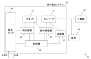
- FIG. 6 is a block diagram illustrating an example of a power generation system including the product (fuel cell stack) and a CPU (controller).
- the power generation system 31 includes, for example, a fuel cell system 32.
- the fuel cell system 32 performs a steam reforming, an aqueous shift reaction, and a selective oxidation reaction on a source gas such as city gas to produce a fuel gas mainly composed of hydrogen.
- An inverter 35 that exchanges electric power with AC power
- a controller (CPU) 36 that controls a series of operations of starting, generating, terminating, and stopping the fuel cell system 32, and stacking air containing oxygen with an oxidant gas 34
- a heat exchanger 38 that collects heat generated when the stack 34 generates power and stores it in a water storage tank as hot water.
- the fuel cell system 32 is connected to commercial AC via a distribution board 39 installed in the home, for example.
- a load 40 such as a home appliance or an industrial product is connected between the distribution board 39 and the fuel cell system.
- electricity is supplied to the load 40 via the inverter 35, the load 40 is operated, and the heat generated by the power generation of the stack 34 is also utilized so that hot water is efficiently supplied to the water storage tank 31. It is configured to be stored.
- said household appliances and industrial products it is not specifically limited, For example, white goods (for example, an air-conditioner, a refrigerator, a washing machine, etc.), audio equipment, domestic household appliances, video equipment, beauty barber equipment, a personal computer, Examples include game machines, portable terminals, business equipment, CPU-equipped equipment, and the like.
- the conductive member of the present invention is useful in any system in which a fuel cell such as a power generation system that requires a long life can be used.
- the mist CVD apparatus 1 includes a carrier gas source 2a for supplying a carrier gas, a flow rate adjusting valve 3a for adjusting the flow rate of the carrier gas delivered from the carrier gas source 2a, and a carrier gas for supplying a carrier gas (dilution) A dilution source 2b, a flow rate adjusting valve 3b for adjusting the flow rate of the carrier gas (dilution) sent from the carrier gas (dilution) source 2b, a mist generating source 4 in which the raw material solution 4a is accommodated, and water 5a.
- An installed hot plate 8 and an exhaust port 11 for exhausting mist, droplets and exhaust gas after thermal reaction are provided.
- a substrate 10 is installed on the hot plate 8.
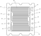
- the separator 12 used in the present example is a separator having a serpentine type flow path pattern, and reacts with the concave portion 13 and the convex portion 14 formed by pressing on a base material made of stainless steel (SUS304) and each single cell.
- a manifold 15 for supplying gas and refrigerant is provided.
- the ultrasonic vibrator 6 was vibrated at 2.4 MHz, and the vibration was propagated to the raw material solution 4a through the water 5a, whereby the raw material solution 4a was atomized to generate the mist 4b.
- the mist 4b is introduced into the film forming chamber 7 by the carrier gas through the supply pipe 9, and the mist reacts thermally near the substrate 10 at 450 ° C. under atmospheric pressure.
- a film was formed.
- the film thickness was 90 nm.
- the obtained film was a film having excellent adhesion without causing peeling or the like.
- Comparative Example 1 As a comparative example, evaluation was performed using a stainless steel (SUS304) base material as it was.
- Comparative Example 2 As a comparative example, evaluation was performed using a conductive member in which a film made of titanium nitride was formed on the same base material as in Example 1 using a sputtering method.
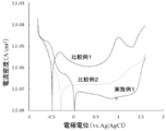
- ⁇ Evaluation test> As an evaluation test of the manufactured conductive member, a polarization test, a contact area resistivity measurement, and a corrosion resistance test were performed. The polarization test was performed using the anodic polarization method. In the polarization test, the exposed area of the conductive member obtained in Example 1, Comparative Example 1 and Comparative Example 2 was measured as 1 cm 2 .
- the test solution was prepared by degassing a sulfuric acid aqueous solution adjusted to pH 3 with nitrogen, and the solution temperature was 25 ° C. In the measurement, an electrochemical measurement system (Solartron SI1287 type) was used, the reference electrode was an Ag / AgCl electrode in saturated potassium chloride, and the counter electrode was a Pt line.
- the potential sweep range was ⁇ 0.8 to 1.6 V (vs. Ag / AgCl), the sweep rate was 1 mV / sec, and polarization was performed in a noble direction.
- FIG. 4 shows the results of the polarization test. It can be seen that the stainless steel (SUS304) base material of Comparative Example 1 has a typical anodic polarization curve in which all regions of the active state potential region, the passive potential region, and the hyperpassive potential region appear. On the other hand, it can be seen that the conductive member obtained in Example 1 shows a polarization curve that directly enters the passive potential region from the natural potential. Further, the natural potential of the conductive member obtained in Example 1 is noble compared to the conductive members obtained in Comparative Examples 1 and 2, and the current density in the passive potential region is 1 ⁇ 10 ⁇ 7 A.
- the passivation potential region is ranging from about 0V to about 1.7V (vs.SHE). From this, the conductive member obtained in Example 1 is excellent in corrosion resistance even in an acidic atmosphere where the separator is exposed in a fuel cell power generation environment and in a highly corrosive situation where a potential of 1.0 V is applied. Recognize.
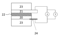
- the contact area resistivity was measured using the test apparatus shown in FIG.
- the conductive wires 24 welded to the electrode plate 21 and the separator 20 via the carbon sheet 22 (TGP-H-060 manufactured by Toray Industries, Inc.) are arranged on the coated surface of the separator 20, respectively.
- the pressure holding member 23 made of an insulating plate is arranged on the outside, and the pressure holding member 23 is pressed so as to be clamped from both sides to set the members in close contact with each other. Then, an ammeter and a voltmeter are connected between the pair of electrode plates 21 and the conductive wire 24.
- the surface pressure applied to the pressure holding member 23 was 400 N, the size of the carbon sheet 22 was set to 1 cm ⁇ 1 cm, and the contact area of the separator was 1 cm 2 .
- the resistance value is determined from the current value and voltage value in each case. Asked.
- the product of the obtained resistance value and the area value of the separator was defined as the contact area resistivity.
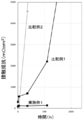
- the separator was immersed in sulfuric acid adjusted to pH 2.0 and heated to 60 ° C. for 550 hours. Corrosion resistance was evaluated by measuring the contact area resistivity before and after the test and evaluating the change.
- FIG. 5 shows changes in contact resistivity before and after the corrosion resistance test for the separators obtained in Example 1, Comparative Example 1 and Comparative Example 2.
- Example 1 and Comparative Examples 1 and 2 have sufficient conductivity because the contact resistance before the corrosion resistance test is 100 m ⁇ ⁇ cm 2 or less. Further, in Comparative Examples 1 and 2, the resistance greatly increased with the passage of time, but in Example 1, the increase in contact resistance was very small, and maintained below 500 m ⁇ ⁇ cm 2 even after 550 hours. I understood. From this, it can be seen that the membrane obtained in Example 1 is less likely to cause a decrease in output during long-term operation of a fuel cell or the like and is excellent in durability.
- the conductive member of the present invention has excellent corrosion resistance even in a high potential environment.
- the conductive member of the present invention has excellent corrosion resistance even in a high potential environment, and when used in a fuel cell, can exhibit corrosion resistance over almost the entire potential range of interest when used, Since the life of the fuel cell can be increased, it can be used in a wide variety of fields using a conductive member. Particularly, for manufacturing various electronic devices including a separator for a fuel cell and products equipped with the various electronic devices. Useful.
- the method for producing a conductive member of the present invention can easily and easily form a conductive metal oxide film with good adhesion to the base material in an industrially advantageous manner.
- a conductive member formed with a film and in particular, a current collector, an electromagnetic wave shielding material, an electrode, a heat radiating plate, a heat radiating component, an electronic component, a semiconductor component, a fuel cell separator, etc. This is useful for manufacturing electronic devices including various parts.
Landscapes
- Chemical & Material Sciences (AREA)
- Engineering & Computer Science (AREA)
- Electrochemistry (AREA)
- General Chemical & Material Sciences (AREA)
- Manufacturing & Machinery (AREA)
- Sustainable Development (AREA)
- Sustainable Energy (AREA)
- Chemical Kinetics & Catalysis (AREA)
- Life Sciences & Earth Sciences (AREA)
- Materials Engineering (AREA)
- Mechanical Engineering (AREA)
- Metallurgy (AREA)
- Organic Chemistry (AREA)
- Composite Materials (AREA)
- Ceramic Engineering (AREA)
- Fuel Cell (AREA)
Abstract
L'invention concerne un élément conducteur ayant une excellente résistance à la corrosion même dans des environnements à haute tension, et un procédé de fabrication de l'élément conducteur. Grâce à l'utilisation d'une solution de base contenant un métal tétravalent pour former un film d'oxyde métallique sur un substrat de séparateur au moyen d'un dépôt chimique en phase vapeur à brume, un élément conducteur, dans lequel une région à potentiel actif et une région à potentiel passif sont formées dans la courbe de polarisation d'anode mesurée dans une solution d'acide sulfurique aqueuse ayant une concentration d'acide sulfurique de 5,0×10⁻⁴ mol/dm3 à un pH de 3 et une température de 25 ℃ de telle sorte que la densité de courant d'anode dans la région à potentiel passif n'est pas supérieure à 1×10⁻⁷ A/cm2 et la région à potentiel passif s'étend jusqu'à un potentiel de 1V, est obtenu.
Priority Applications (2)
| Application Number | Priority Date | Filing Date | Title |
|---|---|---|---|
| US16/608,283 US11189846B2 (en) | 2017-04-28 | 2018-04-27 | Electrically-conductive member and method of manufacturing the same |
| JP2019514685A JP7092280B2 (ja) | 2017-04-28 | 2018-04-27 | 導電性部材およびその製造方法 |
Applications Claiming Priority (4)
| Application Number | Priority Date | Filing Date | Title |
|---|---|---|---|
| JP2017-089171 | 2017-04-28 | ||
| JP2017-089170 | 2017-04-28 | ||
| JP2017089170 | 2017-04-28 | ||
| JP2017089171 | 2017-04-28 |
Publications (1)
| Publication Number | Publication Date |
|---|---|
| WO2018199327A1 true WO2018199327A1 (fr) | 2018-11-01 |
Family
ID=63919045
Family Applications (1)
| Application Number | Title | Priority Date | Filing Date |
|---|---|---|---|
| PCT/JP2018/017306 Ceased WO2018199327A1 (fr) | 2017-04-28 | 2018-04-27 | Élément conducteur et son procédé de fabrication |
Country Status (3)
| Country | Link |
|---|---|
| US (1) | US11189846B2 (fr) |
| JP (1) | JP7092280B2 (fr) |
| WO (1) | WO2018199327A1 (fr) |
Cited By (5)
| Publication number | Priority date | Publication date | Assignee | Title |
|---|---|---|---|---|
| JP2019192437A (ja) * | 2018-04-23 | 2019-10-31 | トヨタ自動車株式会社 | 燃料電池セパレータ、アンチモンドープ酸化スズ及びその製造方法、並びに、燃料電池セパレータの製造方法 |
| JP2020080275A (ja) * | 2018-11-14 | 2020-05-28 | トヨタ自動車株式会社 | 燃料電池用セパレータの製造方法 |
| CN112290223A (zh) * | 2020-09-27 | 2021-01-29 | 南京大学 | 一种极化可编程超构表面及宽带动态波束调控方法 |
| CN112626415A (zh) * | 2020-12-08 | 2021-04-09 | 北京科技大学 | 一种耐应力腐蚀海洋用低合金高强钢的二元合金设计方法 |
| JP2023088640A (ja) * | 2021-12-15 | 2023-06-27 | 東芝三菱電機産業システム株式会社 | 燃料電池セパレータ及び燃料電池セパレータの製造方法 |
Citations (12)
| Publication number | Priority date | Publication date | Assignee | Title |
|---|---|---|---|---|
| JP2004002960A (ja) * | 2002-03-13 | 2004-01-08 | Nisshin Steel Co Ltd | 燃料電池セパレータ用オーステナイト系ステンレス鋼及びその製造方法 |
| JP2004095440A (ja) * | 2002-09-02 | 2004-03-25 | Daido Steel Co Ltd | 燃料電池用金属部材とその製造方法及び燃料電池 |
| JP2004232074A (ja) * | 2002-03-28 | 2004-08-19 | Nisshin Steel Co Ltd | 燃料電池セパレータ用フェライト系ステンレス鋼及びその製造方法 |
| JP2006253089A (ja) * | 2005-03-14 | 2006-09-21 | Toyota Motor Corp | 燃料電池用メタルセパレータとその製造方法 |
| JP2009224151A (ja) * | 2008-03-14 | 2009-10-01 | Nissan Motor Co Ltd | 燃料電池セパレータ |
| JP2011117029A (ja) * | 2009-12-02 | 2011-06-16 | Toyota Central R&D Labs Inc | 耐食導電性皮膜とその製造方法、耐食導電材、固体高分子型燃料電池およびそのセパレータ |
| JP2011243327A (ja) * | 2010-05-14 | 2011-12-01 | Air Water Inc | セパレータの製造方法およびその製造方法によって製造されたセパレータを用いた固体高分子型燃料電池 |
| JP2013129896A (ja) * | 2011-12-22 | 2013-07-04 | Kurimoto Ltd | ステンレス部材、その製造方法、固体高分子型燃料電池に用いるセパレータおよびその製造方法 |
| WO2015159467A1 (fr) * | 2014-04-15 | 2015-10-22 | Jfeスチール株式会社 | Feuille en acier inoxydable pour séparateur de pile à combustible à électrolyte polymère |
| JP2016064961A (ja) * | 2014-09-25 | 2016-04-28 | 株式会社Flosfia | 結晶性積層構造体の製造方法および半導体装置 |
| JP2016126988A (ja) * | 2015-01-08 | 2016-07-11 | 株式会社Flosfia | 透明導電膜および積層構造体 |
| JP2017021948A (ja) * | 2015-07-09 | 2017-01-26 | 昭和電工株式会社 | 燃料電池用セパレータ材料及びその製造方法 |
Family Cites Families (8)
| Publication number | Priority date | Publication date | Assignee | Title |
|---|---|---|---|---|
| JPH11126620A (ja) * | 1997-10-22 | 1999-05-11 | Toyota Central Res & Dev Lab Inc | 燃料電池用セパレータ |
| JP4366872B2 (ja) | 2000-03-13 | 2009-11-18 | トヨタ自動車株式会社 | 燃料電池用ガスセパレータおよび該燃料電池用セパレータの製造方法並びに燃料電池 |
| US8900379B2 (en) | 2003-10-07 | 2014-12-02 | Jfe Steel Corporation | Stainless steel for solid polymer fuel cell separator and solid polymer typefuel cell using the stainless steel |
| KR100851687B1 (ko) | 2004-03-18 | 2008-08-11 | 제이에프이 스틸 가부시키가이샤 | 통전부재용 금속재료, 그것을 사용한 연료전지용 세퍼레이터 및 그 연료전지 |
| US20060134501A1 (en) | 2004-11-25 | 2006-06-22 | Lee Jong-Ki | Separator for fuel cell, method for preparing the same, and fuel cell stack comprising the same |
| JP5573039B2 (ja) | 2009-07-27 | 2014-08-20 | Jfeスチール株式会社 | 固体高分子形燃料電池セパレータ用ステンレス鋼およびその製造方法 |
| JP5832405B2 (ja) | 2012-09-24 | 2015-12-16 | 大阪瓦斯株式会社 | 保護膜形成方法、セル接続部材の製造方法および固体酸化物型燃料電池用セルの製造方法 |
| KR101903180B1 (ko) | 2016-12-22 | 2018-10-01 | 주식회사 포스코 | 접촉저항이 우수한 고분자 연료전지 분리판용 스테인리스강 및 이의 제조 방법 |
-
2018
- 2018-04-27 WO PCT/JP2018/017306 patent/WO2018199327A1/fr not_active Ceased
- 2018-04-27 US US16/608,283 patent/US11189846B2/en not_active Expired - Fee Related
- 2018-04-27 JP JP2019514685A patent/JP7092280B2/ja not_active Expired - Fee Related
Patent Citations (12)
| Publication number | Priority date | Publication date | Assignee | Title |
|---|---|---|---|---|
| JP2004002960A (ja) * | 2002-03-13 | 2004-01-08 | Nisshin Steel Co Ltd | 燃料電池セパレータ用オーステナイト系ステンレス鋼及びその製造方法 |
| JP2004232074A (ja) * | 2002-03-28 | 2004-08-19 | Nisshin Steel Co Ltd | 燃料電池セパレータ用フェライト系ステンレス鋼及びその製造方法 |
| JP2004095440A (ja) * | 2002-09-02 | 2004-03-25 | Daido Steel Co Ltd | 燃料電池用金属部材とその製造方法及び燃料電池 |
| JP2006253089A (ja) * | 2005-03-14 | 2006-09-21 | Toyota Motor Corp | 燃料電池用メタルセパレータとその製造方法 |
| JP2009224151A (ja) * | 2008-03-14 | 2009-10-01 | Nissan Motor Co Ltd | 燃料電池セパレータ |
| JP2011117029A (ja) * | 2009-12-02 | 2011-06-16 | Toyota Central R&D Labs Inc | 耐食導電性皮膜とその製造方法、耐食導電材、固体高分子型燃料電池およびそのセパレータ |
| JP2011243327A (ja) * | 2010-05-14 | 2011-12-01 | Air Water Inc | セパレータの製造方法およびその製造方法によって製造されたセパレータを用いた固体高分子型燃料電池 |
| JP2013129896A (ja) * | 2011-12-22 | 2013-07-04 | Kurimoto Ltd | ステンレス部材、その製造方法、固体高分子型燃料電池に用いるセパレータおよびその製造方法 |
| WO2015159467A1 (fr) * | 2014-04-15 | 2015-10-22 | Jfeスチール株式会社 | Feuille en acier inoxydable pour séparateur de pile à combustible à électrolyte polymère |
| JP2016064961A (ja) * | 2014-09-25 | 2016-04-28 | 株式会社Flosfia | 結晶性積層構造体の製造方法および半導体装置 |
| JP2016126988A (ja) * | 2015-01-08 | 2016-07-11 | 株式会社Flosfia | 透明導電膜および積層構造体 |
| JP2017021948A (ja) * | 2015-07-09 | 2017-01-26 | 昭和電工株式会社 | 燃料電池用セパレータ材料及びその製造方法 |
Cited By (9)
| Publication number | Priority date | Publication date | Assignee | Title |
|---|---|---|---|---|
| JP2019192437A (ja) * | 2018-04-23 | 2019-10-31 | トヨタ自動車株式会社 | 燃料電池セパレータ、アンチモンドープ酸化スズ及びその製造方法、並びに、燃料電池セパレータの製造方法 |
| JP7020269B2 (ja) | 2018-04-23 | 2022-02-16 | トヨタ自動車株式会社 | 燃料電池セパレータ、アンチモンドープ酸化スズ及びその製造方法、並びに、燃料電池セパレータの製造方法 |
| JP2020080275A (ja) * | 2018-11-14 | 2020-05-28 | トヨタ自動車株式会社 | 燃料電池用セパレータの製造方法 |
| JP7031564B2 (ja) | 2018-11-14 | 2022-03-08 | トヨタ自動車株式会社 | 燃料電池用セパレータの製造方法 |
| CN112290223A (zh) * | 2020-09-27 | 2021-01-29 | 南京大学 | 一种极化可编程超构表面及宽带动态波束调控方法 |
| CN112290223B (zh) * | 2020-09-27 | 2021-06-18 | 南京大学 | 一种极化可编程超构表面及宽带动态波束调控方法 |
| CN112626415A (zh) * | 2020-12-08 | 2021-04-09 | 北京科技大学 | 一种耐应力腐蚀海洋用低合金高强钢的二元合金设计方法 |
| JP2023088640A (ja) * | 2021-12-15 | 2023-06-27 | 東芝三菱電機産業システム株式会社 | 燃料電池セパレータ及び燃料電池セパレータの製造方法 |
| JP7662504B2 (ja) | 2021-12-15 | 2025-04-15 | 株式会社Tmeic | 燃料電池セパレータ及び燃料電池セパレータの製造方法 |
Also Published As
| Publication number | Publication date |
|---|---|
| US20200127302A1 (en) | 2020-04-23 |
| JP7092280B2 (ja) | 2022-06-28 |
| US11189846B2 (en) | 2021-11-30 |
| JPWO2018199327A1 (ja) | 2020-05-07 |
Similar Documents
| Publication | Publication Date | Title |
|---|---|---|
| CN108690969B (zh) | 成膜方法、导电性层压结构体及电子装置 | |
| JP7092280B2 (ja) | 導電性部材およびその製造方法 | |
| JP6789490B2 (ja) | 燃料電池用セパレータ及びその製造方法 | |
| JP4884401B2 (ja) | 伝導性親水性燃料電池要素の製造方法 | |
| JP4966112B2 (ja) | Pem型燃料電池用の低コスト双極板被覆 | |
| Park et al. | Low-cost and high-performance anion-exchange membrane water electrolysis stack using non-noble metal-based materials | |
| JPWO2018155503A1 (ja) | 陽極、水電解用陽極、電解セル、及び水素の製造方法 | |
| CN115697553A (zh) | 具有不含铂族金属的自支撑析氧电极的阴离子交换膜电解槽 | |
| US20130330654A1 (en) | Method of depositing durable thin gold coating on fuel cell bipolar plates | |
| JP6150265B2 (ja) | セル、燃料電池スタック、燃料電池システムおよび膜−電極接合体 | |
| WO2013111586A1 (fr) | Dispositif de réduction électrochimique et procédé de production d'un composé aromatique hétérocyclique contenant de l'hydrure d'azote ou un composé d'hydrocarbure aromatique | |
| JP5072652B2 (ja) | 水電解装置 | |
| JP6113715B2 (ja) | 電気化学還元装置および、芳香族炭化水素化合物または含窒素複素環式芳香族化合物の水素化体の製造方法 | |
| US20190165383A1 (en) | Layered structure, electronic device including layered structure, system including electronic device, and method of manufacturing layered structure | |
| JP2007048753A (ja) | TiO2層及び伝導層が形成された接触要素を有する燃料電池 | |
| WO2010055365A1 (fr) | Couche mince de catalyseur et son procédé de fabrication | |
| CN111188025B (zh) | 燃料电池用隔板的制造方法 | |
| JP5809307B2 (ja) | 触媒薄層およびその製造方法 | |
| EP4184618A1 (fr) | Procédé de formation d'une membrane catalytiquement active ou d'un ensemble membrane-électrode | |
| JP2010219034A (ja) | ガス拡散電極、ガス拡散電極の製造方法、燃料電池および食塩電解セル | |
| JP7014353B2 (ja) | 結晶性積層構造体 | |
| JP7054850B2 (ja) | 結晶性積層構造体の製造方法 | |
| JP2019192570A (ja) | 燃料電池用セパレータ | |
| JP2024120570A (ja) | セパレータ | |
| JP2024120571A (ja) | セパレータ |
Legal Events
| Date | Code | Title | Description |
|---|---|---|---|
| 121 | Ep: the epo has been informed by wipo that ep was designated in this application |
Ref document number: 18792159 Country of ref document: EP Kind code of ref document: A1 |
|
| ENP | Entry into the national phase |
Ref document number: 2019514685 Country of ref document: JP Kind code of ref document: A |
|
| NENP | Non-entry into the national phase |
Ref country code: DE |
|
| 122 | Ep: pct application non-entry in european phase |
Ref document number: 18792159 Country of ref document: EP Kind code of ref document: A1 |