WO2018199332A1 - Câble de commande - Google Patents
Câble de commande Download PDFInfo
- Publication number
- WO2018199332A1 WO2018199332A1 PCT/JP2018/017323 JP2018017323W WO2018199332A1 WO 2018199332 A1 WO2018199332 A1 WO 2018199332A1 JP 2018017323 W JP2018017323 W JP 2018017323W WO 2018199332 A1 WO2018199332 A1 WO 2018199332A1
- Authority
- WO
- WIPO (PCT)
- Prior art keywords
- flexible shaft
- molding
- winding
- outer periphery
- grease
- Prior art date
- Legal status (The legal status is an assumption and is not a legal conclusion. Google has not performed a legal analysis and makes no representation as to the accuracy of the status listed.)
- Ceased
Links
Images

Classifications
-
- F—MECHANICAL ENGINEERING; LIGHTING; HEATING; WEAPONS; BLASTING
- F16—ENGINEERING ELEMENTS AND UNITS; GENERAL MEASURES FOR PRODUCING AND MAINTAINING EFFECTIVE FUNCTIONING OF MACHINES OR INSTALLATIONS; THERMAL INSULATION IN GENERAL
- F16C—SHAFTS; FLEXIBLE SHAFTS; ELEMENTS OR CRANKSHAFT MECHANISMS; ROTARY BODIES OTHER THAN GEARING ELEMENTS; BEARINGS
- F16C1/00—Flexible shafts; Mechanical means for transmitting movement in a flexible sheathing
- F16C1/02—Flexible shafts; Mechanical means for transmitting movement in a flexible sheathing for conveying rotary movements
- F16C1/08—End connections
-
- F—MECHANICAL ENGINEERING; LIGHTING; HEATING; WEAPONS; BLASTING
- F16—ENGINEERING ELEMENTS AND UNITS; GENERAL MEASURES FOR PRODUCING AND MAINTAINING EFFECTIVE FUNCTIONING OF MACHINES OR INSTALLATIONS; THERMAL INSULATION IN GENERAL
- F16C—SHAFTS; FLEXIBLE SHAFTS; ELEMENTS OR CRANKSHAFT MECHANISMS; ROTARY BODIES OTHER THAN GEARING ELEMENTS; BEARINGS
- F16C1/00—Flexible shafts; Mechanical means for transmitting movement in a flexible sheathing
- F16C1/10—Means for transmitting linear movement in a flexible sheathing, e.g. "Bowden-mechanisms"
- F16C1/20—Construction of flexible members moved to and fro in the sheathing
-
- F—MECHANICAL ENGINEERING; LIGHTING; HEATING; WEAPONS; BLASTING
- F16—ENGINEERING ELEMENTS AND UNITS; GENERAL MEASURES FOR PRODUCING AND MAINTAINING EFFECTIVE FUNCTIONING OF MACHINES OR INSTALLATIONS; THERMAL INSULATION IN GENERAL
- F16C—SHAFTS; FLEXIBLE SHAFTS; ELEMENTS OR CRANKSHAFT MECHANISMS; ROTARY BODIES OTHER THAN GEARING ELEMENTS; BEARINGS
- F16C1/00—Flexible shafts; Mechanical means for transmitting movement in a flexible sheathing
- F16C1/24—Lubrication; Lubricating equipment
-
- F—MECHANICAL ENGINEERING; LIGHTING; HEATING; WEAPONS; BLASTING
- F16—ENGINEERING ELEMENTS AND UNITS; GENERAL MEASURES FOR PRODUCING AND MAINTAINING EFFECTIVE FUNCTIONING OF MACHINES OR INSTALLATIONS; THERMAL INSULATION IN GENERAL
- F16C—SHAFTS; FLEXIBLE SHAFTS; ELEMENTS OR CRANKSHAFT MECHANISMS; ROTARY BODIES OTHER THAN GEARING ELEMENTS; BEARINGS
- F16C1/00—Flexible shafts; Mechanical means for transmitting movement in a flexible sheathing
- F16C1/26—Construction of guiding-sheathings or guiding-tubes
Definitions
- the present invention relates to a control cable.
- a control cable has been used as means for connecting an operating portion and an operated portion and transmitting torque by rotating around an axis.
- a conventional control cable for example, a torque cable in which a flexible shaft rotates in an outer casing, and a pile is electrostatically flocked on the entire outer periphery of the flexible shaft is known to prevent vibration and abnormal noise generated during rotation. (For example, Patent Document 1).
- the present invention has been made in view of the above problems, and an object of the present invention is to provide a control cable having smooth slidability with respect to the outer casing when the flexible shaft rotates.
- the control cable according to the present invention includes a flexible shaft having a rigidity capable of transmitting a rotational force, a molding having a core yarn and a pile fixed to the core yarn, and the molding spirals on the outer periphery of the flexible shaft at a predetermined pitch.
- a grease reservoir is formed to hold the water.
- the control cable of the present invention has smooth slidability because the molding is spaced apart at a predetermined pitch and fixed to the outer periphery of the flexible shaft. Further, since the grease reservoir is formed between the moldings spirally wound on the outer periphery of the flexible shaft, the molding inhibits the movement of the grease in the axial direction of the flexible shaft, and the grease is suitably held in the grease reservoir. You can also.
- FIG. 1 It is a side view which shows an example of the control cable of this invention. It is a side view which shows an example of the composite flexible shaft of the control cable of FIG.
- A) is a side view of an example of the flexible shaft of a control cable
- (b) is a side view of another example of the flexible shaft of a control cable.
- (A) is a side view which shows an example of the molding of the control cable of FIG. 1
- (b) is a front view of the molding shown in (a).
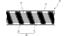
- the control cable 10 includes a flexible shaft 11 having rigidity capable of transmitting a rotational force, a molding 12 having a core yarn and a pile fixed to the core yarn, and the molding 12 includes the flexible shaft 11. And an outer casing 13 in which a composite flexible shaft wound spirally at a predetermined pitch is accommodated.
- a control cable 10 one end of the flexible shaft 11 is connected to the operation portion, and the other end is connected to the operated portion, and torque caused by rotation around the axis applied in the operation portion is obtained.
- the operation target By transmitting to the operated part through the flexible shaft 11, the operation target can be operated.
- a grease reservoir 14 is formed on the outer periphery of the flexible shaft 11 by providing moldings 12 to be described later at a predetermined pitch. The grease 50 applied to the outer periphery of the composite flexible shaft can be held in the grease reservoir 14.
- control cable 10 only needs to transmit the rotational force to the operation target through the flexible shaft 11, and the magnitude of the rotational force is not limited.
- the control cable 10 is configured such that one end of the flexible shaft 11 is connected to the operation unit, and the other end is connected to the operated unit, so that the driving force (torque) generated from the power unit is operated (operated). Part).
- the flexible shaft 11 rotates in the direction around the axis of the flexible shaft 11 and transmits torque from the operation unit to the operated unit.
- the flexible shaft 11 is not particularly limited as long as it can transmit torque, but a torque cable can be used.
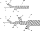
- As the torque cable on the outside of the core wire, there is one wire wound around one side of the core wire in the axial direction, and a wire wound around the other side of the core wire around the axis of the core wire. It is only necessary to have a configuration capable of transmitting torque by rotating the other end by torque input to one end of the torque cable. For example, like the flexible shaft 30a shown in FIG.
- the first winding layer 32 in which the four first windings 32a are wound around the core wire 31 and the outer periphery of the core wire 31, and the first A configuration having the second winding layer 33 in which the four second windings 33 a are wound around the other around the outer periphery of the winding layer 32 can be used.
- the flexible shaft 30a can adopt various layer configurations as appropriate depending on the desired performance such as torque transmission characteristics and flexibility required for the relationship between the core wire and the winding, and is crimped to the end. Various forms such as providing a portion can be employed.
- the wire diameter and the type of the wire material can be appropriately used according to the application.
- a linear galvanized hard steel wire having a diameter of 0.6 to 0.8 mm can be used.
- the 32a and the second winding 33a include a galvanized hard steel wire having a diameter of 0.4 to 0.6 mm.
- the number of windings of the first winding 32a and the second winding 33a is not particularly limited, and is appropriately adjusted according to the use as a control cable.
- the flexible shaft 11 for example, in addition to the flexible shaft 30 a (FIG. 3A) in which two winding layers are provided on the outer periphery of the core wire 31, four winding layers are provided on the outer periphery of the core wire 31. It can be set as the flexible shaft 30b (FIG.3 (b)), A multilayer form can also be employ
- the flexible shaft 11 has a third winding layer 34 composed of five third windings 34 a wound around the outer periphery of the second winding layer 33.
- a fourth winding 35 composed of six fourth windings 35 a is wound around the outer periphery of the winding layer 34. As shown in FIGS.
- the winding directions of the layers of the first winding layer 32a to the fourth winding layer 35a adjacent to each other in the radial direction are opposite to each other. It is preferable. Since the winding directions of adjacent winding layers wound around the outer periphery of the core wire 31 are opposite to each other, torque in the forward rotation direction and the reverse rotation direction of the flexible shaft 11 can be efficiently transmitted. it can.
- the flexible shaft 11 shown in FIG. 3B has a first winding layer 32 made up of four windings 32a each having a circular cross section around the core wire 31 in a predetermined winding direction.
- the second winding layer 33 composed of four windings 33a each having a circular cross section around the layer 32 is arranged around the second winding layer 33 in a direction opposite to the winding direction of the first winding layer 32.
- the fourth winding layer 35 consisting of five windings 34a each having a circular cross section in the direction opposite to the winding direction of the second winding layer 33 and around the third winding layer 34, respectively.
- the fourth winding layer 35 composed of the six windings 35a having the above can be obtained by winding in a direction opposite to the winding direction of the third winding layer 34.
- the flexible shaft 11 is shown as a solid cable (torque cable) in this embodiment, but may be a hollow tube (torque tube) using a coil wire.
- the flexible shaft 11 has a composite flexible shaft 20 in which a molding 12 is spirally wound around the outer periphery at a predetermined pitch.
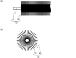
- the molding 12 include a molding 12 having a core yarn 41 and a pile 42 fixed to the outer periphery of the core yarn 41 as shown in FIGS. 4 (a) and 4 (b).
- the molding 12 constituted by the core yarn 41 and the pile 42 and forming the composite flexible shaft 20 in which the molding 12 is spirally provided on the outer periphery of the flexible shaft 11, in the axial direction of the flexible shaft 11.
- interval of the molding 12 is formed and the space where the molding 12 is not provided in the outer peripheral surface of the flexible shaft 11 can be provided.
- the molding 12 comes into contact with the inner peripheral surface of the outer casing 13, and between the moldings 12 in the axial direction of the flexible shaft 11, Since the contact between the outer peripheral surface of the flexible shaft and the inner peripheral surface of the outer casing is hindered by the molding 12, good slidability can be obtained.
- the core yarn 41 constitutes the main body of the molding 12 with the pile 42 fixed thereto.
- the core yarn 41 can be wound around the flexible shaft 11, has a tensile strength that can withstand the tension when wound, and has durability against sliding with the outer casing, the material is not particularly limited, For example, those obtained by bundling thermoplastic resin fibers such as nylon 6, nylon 66, polyester, and cellulose are used.
- the pile 42 is fixed to the core yarn 41 and extends toward the radially outer side of the core yarn 41 to form the molding 12.
- the pile 42 is arrange
- the pile 42 preferably has a flexibility that does not hinder sliding between the outer casing 13 and the flexible shaft 11 and is bent when it comes into contact with the outer casing.
- Such a pile 42 is not particularly limited, and examples thereof include thermoplastic resin fibers such as nylon 6, nylon 66, nylon 6.10, nylon 6.12, and polyester.
- a method for manufacturing the molding 12 for example, a method in which piles 42 are fixed radially to the core yarn 41 by applying an adhesive to the core yarn 41, electrostatic flocking, or the like, or between two core yarns.
- a known method such as a method of arranging a pile in a direction perpendicular to the direction of the core yarn and fixing the pile to the core yarn by twisting the two core yarns (twisted yarn molding) can be used.
- the method for winding the molding 12 around the outer periphery of the flexible shaft 11 is not particularly limited, and examples thereof include the following methods. First, the molding device 12 is rotated while the flexible shaft 11 is fixed so as not to rotate, and the core yarn 41 is brought into contact with the outer periphery of the flexible shaft together with the adhesive yarn composed of a heat-meltable thermoplastic resin. Wind while applying tension. Next, when the flexible shaft 11 is heated to a temperature at which the adhesive yarn is melted by high frequency induction heating while maintaining the tension, the adhesive yarn composed of polyolefin resin or the like is melted, and the core yarn 41 and the flexible shaft 11 The melted adhesive yarn component spreads on the surface of the flexible shaft 11 together with the core yarn 41.
- the molding 12 is heated at a temperature that does not melt, the core yarn 41 and the pile 42 do not melt, and the adhesive yarn melts, so that the flexibility of the pile 42 is maintained and the flexible shaft 11 is maintained.
- the molding 12 can be bonded to the surface.
- the composite flexible shaft 20 can be manufactured by using the flexible shaft 11 prepared in advance.
- the composite flexible shaft continuous body having the molding 12 provided on the outer periphery can be formed into a desired length. It can also be obtained by cutting with a cutting machine so as to form a composite flexible shaft.
- an adhesive thread is used as a method for manufacturing the composite flexible shaft, but a known liquid adhesive can also be used.
- the molding 12 is fixed to the outer periphery of the flexible shaft 11 with a predetermined pitch.
- the molding 12 is spirally wound around the outer periphery of the flexible shaft 11 at a predetermined pitch.
- the molding 12 is wound spirally around the flexible shaft 11, but is wound in a direction including the radial component of the flexible shaft 11.
- the molding 12 may be configured by one molding from one end of the flexible shaft 11 to the other end, or may be configured by a plurality of moldings from one end to the other end of the flexible shaft 11. Further, the molding 12 may be provided in a part of the axial direction of the flexible shaft 11 such as a part necessary for ensuring slidability.
- the molding 12 Since the molding 12 is wound around the axis of the flexible shaft 11 so as to include a radial component, the contact area in the axial direction with the inner surface of the outer casing 13 is reduced. Since the molding 12 includes the core yarn 41, the core yarn 41 is also wound around the flexible shaft 11 when the molding 12 is wound around the axis of the flexible shaft 11. When the composite flexible shaft 20 rotates in the direction around the axis, the molding 12 provided on the composite flexible shaft 20 and the inner surface of the outer casing 13 slide to generate a frictional force. Since it is fixed on the outer periphery of the flexible shaft 11 so as to extend in the circumferential direction, it can be advantageous against peeling of the molding 12 due to the frictional force.
- the molding 12 is wound around the axis of the flexible shaft 11 so as to include a radial component, so that the grease 50 is applied to the composite flexible shaft 20 in the axial direction of the composite flexible shaft 20.
- the movement of is inhibited.
- the mall 12 is composed of a plurality of malls 12 such as a plurality of malls configured as a multiple winding, or by dividing the axial direction of the flexible shaft 11 into a plurality of areas and winding each area with a separate mall. It may be configured.
- the molding 12 is fixed to the outer periphery of the flexible shaft 11, so that the grease reservoir 14 can be formed on the outer periphery of the flexible shaft 11.
- the grease reservoir 14 is formed between the moldings 12 as shown in FIG.
- the molding 12 is provided by repeating a plurality of windings around the axis of the flexible shaft 11.
- the molding 12 uses one round of the circumference of the flexible shaft 11 in the direction around the axis as one repeating unit, and an interval between a predetermined position of one repeating unit and a position corresponding to the predetermined position in the adjacent repeating unit, that is, a predetermined
- the outer surface of the flexible shaft 11 that is not covered by the molding 12 is formed at intervals of the pitch of, and a space is formed by the height of the molding 12 and the outer surface. This space can function as the grease reservoir 14.
- the pitch P of the molding 12 is appropriately set so as to hold a necessary amount of grease 50 according to the size, purpose of use, shape, etc. of the control cable.
- the pitch of the molding 12 can be a distance that can maintain good slidability when the flexible shaft 11 rotates.
- the pitch P can be set to 1 to 10 mm, for example.
- the pitch P of the molding 12 is also the distance between the centers of the core yarns 41 on the upper surface of the adjacent molding 12 when the composite flexible shaft 20 is viewed from the side.
- the pitch P of the molding 12 can be the same as or larger than the pitch P of the outermost winding that constitutes the outer periphery of the flexible shaft 11.
- the pitch of the molding 12 can be set to a predetermined length or more in the axial direction of the flexible shaft 11, the contact area between the inner peripheral surface of the outer casing and the molding in the unit length in the axial direction of the flexible shaft 11 can be reduced. , Better slidability can be ensured.
- a grease reservoir 14 in which the grease 50 is held between the moldings 12 when the pitch P of the moldings 12 is the same as or larger than the pitch P of the outermost winding constituting the outer periphery of the flexible shaft 11. It will be formed large.
- the pitch of the molding 12 ensures characteristics as the molding 12 required for the composite flexible shaft 20 such as slidability and peeling resistance. If it can, it can set so that slidability can be exhibited in the range exceeding 1 time of the pitch P of the said coil
- the winding of the outermost layer which comprises the outer periphery of the flexible shaft 11 corresponds to the winding of the 4th winding layer 35 in embodiment of FIG.3 (b).
- the spiral winding direction of the molding 12 and the outermost layer winding constituting the outer periphery of the flexible shaft 11 is the same as the winding direction of the molding 12 and the winding direction of the outermost winding. May be different.
- the molding 12 may be spirally wound around the outer periphery of the flexible shaft 11 in a state where the pitch P is uniform (regular), and the mallet 12 is formed in a state where the pitch P is not uniform (irregular). It may be wound around the outer periphery.
- the state in which the pitch P is not uniform include, for example, a state in which the vicinity of the end of the outer casing 13 of the flexible shaft 11 has a denser pitch than the vicinity of the center, and conversely the center of the outer casing 13 of the flexible shaft 11.
- a state in which the vicinity has a denser pitch than the vicinity of the end, and when the outer casing 13 has a bent portion or a curved portion, a state in which the bent portion or the curved portion has a denser pitch, A state in which the pitch gradually increases or decreases from one side, a completely random state, and the like can be given. Since the outermost layer of the flexible shaft 11 has a rough winding area, a recess is formed between the windings, the molding 12 abuts against the inner wall surface of the recess, and the axial displacement of the flexible shaft 11 of the molding 12 is prevented. A configuration that is advantageous for prevention and retention of the grease 50 can also be employed.
- the molding 12 may be wound around the entire length of the flexible shaft 11 or may be wound only at a necessary portion of the flexible shaft 11.
- the “required part of the flexible shaft 11” includes, for example, a part inserted into the outer casing 13, such as a part inserted into the outer casing 13 in order to improve slidability and suppress vibrations.
- required is included.
- the outer casing 13 is a member that accommodates the composite flexible shaft 20 described above, and has a role of protecting the composite flexible shaft 20 from friction with an external member.
- the outer casing 13 may be formed with a resin liner or a reinforcing layer of a coiled metal wire on the inner peripheral side.
- Such an outer casing 13 is not particularly limited as long as it has a structure that can accommodate the composite flexible shaft 20 described above.
- Examples of the outer casing 13 include a hollow tube made of a resin such as polyamide, a box-shaped resin case, and the like. However, depending on the application, a reinforcing layer made of a metal wire is provided depending on the application of the control cable. An optimum form including dimensions such as length and diameter is appropriately selected and used.
- the grease 50 exists between the composite flexible shaft 20 and the outer casing 13.
- the grease 50 is applied to the outer periphery of the composite flexible shaft 20 and is held in a grease reservoir 14 formed between the moldings 12 spaced apart at a predetermined pitch in the axial direction of the flexible shaft 11. It may be applied to the outer periphery of the film.
- the outer periphery of the composite flexible shaft 20 includes the outer periphery of the molding 12 in the radial direction of the composite flexible shaft 20. In this case, the grease 50 is held between the molding 12 and the inner surface of the outer casing 13, and the slidability of the flexible shaft 11 can be improved.
- the grease 50 exists on the side facing the outer casing 13 of the molding 12 provided on the outer periphery of the outermost layer of the flexible shaft 11 by winding, and the grease 50 is also present in the gap between the piles 42. included.
- Grease 50 adheres to pile 42 that constitutes molding 12 while being fixed to core yarn 41.
- the grease is not particularly limited, and examples thereof include known lubricants for control cables.
- Examples of the method for producing the control cable 10 of the present invention include the following methods. That is, first, a known flexible shaft 11 is prepared, and the composite flexible shaft 20 is manufactured by spirally winding the outer periphery of the known flexible shaft 11 at a predetermined pitch by the method described above. Examples of the method for manufacturing the composite flexible shaft 20 include any of the methods described above. Next, the terminal member is crimped and fixed to the ends of the flexible shaft 11 and the molding 12. Next, the grease 50 is applied to the entire composite flexible shaft 20. Then, the composite flexible shaft 20 to which the grease 50 is applied is inserted into the outer casing 13. Even when the composite flexible shaft 20 is inserted into the outer casing 13, the grease 50 is held between the moldings. Therefore, the grease 50 is less likely to come out of the outer casing, and the form of the present invention is more advantageous than the conventional form in terms of manufacturing. is there.
- control cable of the present invention one end, that is, one end of the flexible shaft 11 is connected to the operating portion, and the other end, that is, the other end of the flexible shaft 11 is connected to the operated portion.
- An operating mechanism can be configured. Although it does not specifically limit as said operation part by the use of the control cable of this invention, For example, as mentioned above, drive sources, such as a motor, are mentioned.
- the operated portion is also appropriately determined depending on the use of the control cable 10 of the present invention.
- control cable of the present invention is not particularly limited as long as torque is transmitted from the operation unit.
- an operation cable for a vehicle seat and an opening / closing mechanism for a back door, a rotation meter, and an optical axis adjustment And various applications such as a cable for key lock, a mower, a remote control device for opening and closing a window, and the like.
Landscapes
- Engineering & Computer Science (AREA)
- General Engineering & Computer Science (AREA)
- Health & Medical Sciences (AREA)
- Oral & Maxillofacial Surgery (AREA)
- Mechanical Engineering (AREA)
- Flexible Shafts (AREA)
Abstract
La présente invention concerne un câble de commande (10) ayant un arbre flexible (11, etc.) qui est suffisamment rigide pour transmettre une force de rotation, une tresse (12) ayant un fil de noyau (41) et une pile (42) fixée au fil de noyau (41), et un boîtier externe (13) recevant un arbre flexible composite (20) dans lequel la tresse (12) est enroulée en hélice selon un pas prescrit autour de la périphérie externe de l'arbre flexible (11, etc.), la périphérie externe de l'arbre flexible (11, etc.) comportant de la graisse (50), et des réservoirs de graisse (14), dans lesquels la graisse (50) est retenue, étant formés entre les parties de la tresse (12) séparées à un pas prescrit dans la direction axiale de l'arbre flexible (11,etc.). La présente invention permet ainsi d'empêcher de manière appropriée l'apparition de vibrations et de bruit anormal tandis que l'arbre flexible (11, etc.) est en rotation, et également de réduire la résistance contre le coulissement sur le boîtier externe (13) tandis que l'arbre flexible (11, etc.) tourne.
Applications Claiming Priority (2)
| Application Number | Priority Date | Filing Date | Title |
|---|---|---|---|
| JP2017-090290 | 2017-04-28 | ||
| JP2017090290A JP6653289B2 (ja) | 2017-04-28 | 2017-04-28 | コントロールケーブル |
Publications (1)
| Publication Number | Publication Date |
|---|---|
| WO2018199332A1 true WO2018199332A1 (fr) | 2018-11-01 |
Family
ID=63918476
Family Applications (1)
| Application Number | Title | Priority Date | Filing Date |
|---|---|---|---|
| PCT/JP2018/017323 Ceased WO2018199332A1 (fr) | 2017-04-28 | 2018-04-27 | Câble de commande |
Country Status (2)
| Country | Link |
|---|---|
| JP (1) | JP6653289B2 (fr) |
| WO (1) | WO2018199332A1 (fr) |
Cited By (1)
| Publication number | Priority date | Publication date | Assignee | Title |
|---|---|---|---|---|
| CN118815911A (zh) * | 2024-09-04 | 2024-10-22 | 一汽解放汽车有限公司 | 变速器换挡软轴组件及车辆 |
Citations (5)
| Publication number | Priority date | Publication date | Assignee | Title |
|---|---|---|---|---|
| JPS5568712U (fr) * | 1978-11-06 | 1980-05-12 | ||
| JPS55106721U (fr) * | 1979-01-24 | 1980-07-25 | ||
| JPH0234682U (fr) * | 1988-08-26 | 1990-03-06 | ||
| JPH06294460A (ja) * | 1993-04-06 | 1994-10-21 | Nippon Cable Syst Inc | 植毛タイプのインナーケーブル |
| US20150267738A1 (en) * | 2011-09-29 | 2015-09-24 | Shimano Inc. | Bicycle control cable |
-
2017
- 2017-04-28 JP JP2017090290A patent/JP6653289B2/ja active Active
-
2018
- 2018-04-27 WO PCT/JP2018/017323 patent/WO2018199332A1/fr not_active Ceased
Patent Citations (5)
| Publication number | Priority date | Publication date | Assignee | Title |
|---|---|---|---|---|
| JPS5568712U (fr) * | 1978-11-06 | 1980-05-12 | ||
| JPS55106721U (fr) * | 1979-01-24 | 1980-07-25 | ||
| JPH0234682U (fr) * | 1988-08-26 | 1990-03-06 | ||
| JPH06294460A (ja) * | 1993-04-06 | 1994-10-21 | Nippon Cable Syst Inc | 植毛タイプのインナーケーブル |
| US20150267738A1 (en) * | 2011-09-29 | 2015-09-24 | Shimano Inc. | Bicycle control cable |
Cited By (1)
| Publication number | Priority date | Publication date | Assignee | Title |
|---|---|---|---|---|
| CN118815911A (zh) * | 2024-09-04 | 2024-10-22 | 一汽解放汽车有限公司 | 变速器换挡软轴组件及车辆 |
Also Published As
| Publication number | Publication date |
|---|---|
| JP2018189124A (ja) | 2018-11-29 |
| JP6653289B2 (ja) | 2020-02-26 |
Similar Documents
| Publication | Publication Date | Title |
|---|---|---|
| US3581523A (en) | Flexible cable assembly | |
| JP2904767B1 (ja) | フレキシブルシャフトライナーアッセンブリ及び回転伝達シャフト | |
| US3537484A (en) | Filament-wound pipe | |
| JP6554794B2 (ja) | 医療機器 | |
| EP1286065B1 (fr) | Arbre flexible avec un composant pour la réduction de bruit | |
| US3990321A (en) | Push-pull, cable-type actuator | |
| JP2022100376A (ja) | 光ファイバケーブル | |
| EP3911875A1 (fr) | Agencement de poulie et de câble | |
| JP6653289B2 (ja) | コントロールケーブル | |
| JPH02291305A (ja) | ケーブル搬送装置 | |
| EP2781771B1 (fr) | Arbre flexible ayant une capacité d'adaptation à l'interférence | |
| JP7184526B2 (ja) | 光ファイバケーブル | |
| EP3290127A1 (fr) | Arbre de torsion flexible et agencement l'utilisant et dispositif de nettoyage de conduits de climatisation | |
| US20130087008A1 (en) | Sliding cable and control cable | |
| US4655729A (en) | Flexible cable assembly | |
| US4716001A (en) | Method of making a flexible cable assembly | |
| JP4386505B2 (ja) | 管軸方向に補強されたプラスチックパイプ | |
| JP2014095188A (ja) | 開閉装置 | |
| JP2020152466A (ja) | 長尺体用リールのブレーキング構造 | |
| US20080220883A1 (en) | Low noise and vibration flexible shaft assembly | |
| JP7505928B2 (ja) | 有歯ケーブルおよび駆動装置 | |
| EP2733370A1 (fr) | Gaine pour câble Bowden | |
| EP4544211A1 (fr) | Tube multicouche pliable | |
| JP2013104473A (ja) | 合成樹脂製ホースとその製造方法 | |
| JP2004263818A (ja) | コントロールケーブル |
Legal Events
| Date | Code | Title | Description |
|---|---|---|---|
| 121 | Ep: the epo has been informed by wipo that ep was designated in this application |
Ref document number: 18792085 Country of ref document: EP Kind code of ref document: A1 |
|
| NENP | Non-entry into the national phase |
Ref country code: DE |
|
| 122 | Ep: pct application non-entry in european phase |
Ref document number: 18792085 Country of ref document: EP Kind code of ref document: A1 |