WO2018202761A1 - Appareil électroménager comprenant une pompe à chaleur - Google Patents
Appareil électroménager comprenant une pompe à chaleur Download PDFInfo
- Publication number
- WO2018202761A1 WO2018202761A1 PCT/EP2018/061320 EP2018061320W WO2018202761A1 WO 2018202761 A1 WO2018202761 A1 WO 2018202761A1 EP 2018061320 W EP2018061320 W EP 2018061320W WO 2018202761 A1 WO2018202761 A1 WO 2018202761A1
- Authority
- WO
- WIPO (PCT)
- Prior art keywords
- condenser
- electric heater
- household appliance
- drying
- refrigerant
- Prior art date
- Legal status (The legal status is an assumption and is not a legal conclusion. Google has not performed a legal analysis and makes no representation as to the accuracy of the status listed.)
- Ceased
Links
Images



Classifications
-
- D—TEXTILES; PAPER
- D06—TREATMENT OF TEXTILES OR THE LIKE; LAUNDERING; FLEXIBLE MATERIALS NOT OTHERWISE PROVIDED FOR
- D06F—LAUNDERING, DRYING, IRONING, PRESSING OR FOLDING TEXTILE ARTICLES
- D06F58/00—Domestic laundry dryers
- D06F58/20—General details of domestic laundry dryers
- D06F58/206—Heat pump arrangements
-
- A—HUMAN NECESSITIES
- A47—FURNITURE; DOMESTIC ARTICLES OR APPLIANCES; COFFEE MILLS; SPICE MILLS; SUCTION CLEANERS IN GENERAL
- A47L—DOMESTIC WASHING OR CLEANING; SUCTION CLEANERS IN GENERAL
- A47L15/00—Washing or rinsing machines for crockery or tableware
- A47L15/42—Details
- A47L15/48—Drying arrangements
-
- A—HUMAN NECESSITIES
- A47—FURNITURE; DOMESTIC ARTICLES OR APPLIANCES; COFFEE MILLS; SPICE MILLS; SUCTION CLEANERS IN GENERAL
- A47L—DOMESTIC WASHING OR CLEANING; SUCTION CLEANERS IN GENERAL
- A47L15/00—Washing or rinsing machines for crockery or tableware
- A47L15/42—Details
- A47L15/48—Drying arrangements
- A47L15/483—Drying arrangements by using condensers
-
- D—TEXTILES; PAPER
- D06—TREATMENT OF TEXTILES OR THE LIKE; LAUNDERING; FLEXIBLE MATERIALS NOT OTHERWISE PROVIDED FOR
- D06F—LAUNDERING, DRYING, IRONING, PRESSING OR FOLDING TEXTILE ARTICLES
- D06F58/00—Domestic laundry dryers
- D06F58/20—General details of domestic laundry dryers
- D06F58/24—Condensing arrangements
-
- D—TEXTILES; PAPER
- D06—TREATMENT OF TEXTILES OR THE LIKE; LAUNDERING; FLEXIBLE MATERIALS NOT OTHERWISE PROVIDED FOR
- D06F—LAUNDERING, DRYING, IRONING, PRESSING OR FOLDING TEXTILE ARTICLES
- D06F58/00—Domestic laundry dryers
- D06F58/20—General details of domestic laundry dryers
- D06F58/26—Heating arrangements, e.g. gas heating equipment
Definitions
- the present invention relates to a heat pump household appliance wherein the drying process is realized.
- the drying process is realized by passing the drying air over the items placed in the drying chamber.
- heat pump drying systems are preferred as the latter generally consumes less energy than the drying systems wherein electric heaters are used for heating the drying air.
- the heat pump comprises a compressor that provides the circulation of the refrigerant by pressurizing the same, an evaporator that enables the drying air to be condensed, and a condenser that enables the drying air to be heated.
- the drying air heats up slower than the drying systems wherein electric heaters are used, thus causing the drying process to take more time and failing to reach high temperature values required for hygiene.
- the aim of the present invention is the realization of a heat pump household appliance wherein the drying process is performed in an efficient manner.
- the household appliance realized in order to attain the aim of the present invention, explicated in the first claim and the respective claims thereof is of heat pump type, comprising a compressor that enables the refrigerant circulation to be performed, an evaporator that condenses the drying air, and a condenser that heats the dehumidified drying air coming from the evaporator.
- the refrigerant circulated in the heat pump heats the surface of the condenser while passing through the refrigerant tube of the condenser and the drying air is heated by being passed over the hot surfaces of the condenser before being delivered to the drying chamber.
- the household appliance of the present invention comprises at least one electric heater that contacts the surface of the condenser so as to enable the surface temperature of the condenser to be further increased during the drying process.
- the electric heater enables the surface of the condenser to be quickly and effectively heated by contact.
- the condenser is enabled to be directly heated by means of the electric heater, the heat losses are reduced and the drying process is performed more efficiently and quickly.
- the time needed for the heat pump system to start heating the drying air with maximum efficiency is shortened.
- the electric heater is of resistance type in the form of a tube.
- the surface area of the heater is advantageously expanded and the amount of heat transferred to the condenser is increased.
- the electric heater extends in the circulation duct on a plane perpendicular to the flow direction of the drying air.
- the electric heater is enabled to contact also the drying air passed over the condenser and the temperature of the drying air is effectively increased.
- the electric heater is arranged on the condenser so as to extend on the outer surface of the refrigerant tube.
- the condenser comprises fins that extend on the refrigerant tube, through which the drying air is passed and the electric heater extends on the condenser fins.
- the condenser fins form a large portion of the hot surface of the condenser, a homogeneous heat distribution is provided on the condenser surface and the drying air is effectively heated by arranging the electric heater on the fins.
- a housing formed as a recess matching the form of the heater is provided, wherein the heater is placed into the housing.
- the electric heater is almost completely embedded in the condenser surface, and the heat transfer between the electric heater and the condenser is improved as the former is surrounded by the fins.
- a plurality of vanes extending parallel to each other are provided on the tube-shaped electric heater.
- the electric heater is disposed adjacent to the condenser in the circulation duct and almost the same air passes over both the condenser and the electric heater.
- the condenser By means of the present invention, by increasing the surface temperature of the condenser quickly, the condenser is enabled to efficiently heat the drying air from the beginning of the drying process. Thus, the drying process is enabled to be completed quickly and energy losses are minimized. Moreover, by means of the present invention, by positioning the electric heater and the condenser next to each other, the volume in the body can be used effectively.
- Figure 1 is the schematic view of the household appliance related to an embodiment of the present invention.
- Figure 2 – is the partial view of the household appliance related to an embodiment of the present invention.
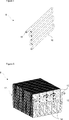
- Figure 3 — is the view of the condenser and the electric heater related to an embodiment of the present invention.
- Figure 4 – is the view of the electric heater related to another embodiment of the present invention.
- Figure 5 — is the view of the condenser related to another embodiment of the present invention.
- Figure 6 — is the view of the condenser and the electric heater related to another embodiment of the present invention.
- the household appliance (1) comprises a body (2); a drying chamber (3) arranged in the body (2) and wherein the drying process is realized; an air duct (4) with ends opening into the drying chamber (3) and through which the drying air is passed, and a heat pump (5) wherein the refrigerant cycle is realized, that has a compressor (6) enabling the refrigerant to be sucked and pumped, an evaporator (7) enabling the moisture in the drying air in the air duct (4) to be removed and a condenser (8) enabling the drying air to be heated and having at least one serpentine shaped refrigerant tube (10) through which the refrigerant is circulated.
- the refrigerant pumped by the compressor (6) returns to the compressor (6) after being passed through the condenser (8) and the evaporator (7).
- the refrigerant leaving the compressor (6) with increased pressure and temperature increases the surface temperature of the condenser (8) while passing through the refrigerant tube (10) of the condenser (8) and thus, the drying air passed over the hot surfaces of the condenser (8) is heated.
- the household appliance (1) of the present invention comprises at least one electric heater (9) that is arranged in the circulation duct (4) so as to contact the condenser (8) and that enables the surface temperature of the condenser (8) to be increased.
- the electric heater (9) contacts at least one surface of the condenser (8) so as to enable the heat to be transferred directly to the condenser (8).
- the condenser (8) is enabled to quickly reach temperature values higher than the values obtained in conventional heat pump systems.
- the drying performance of the household appliance (1) is effectively increased and energy saving is provided.
- the electric heater (9) is in the form of a tube.
- the electric heater (9) is of resistance type, comprising a tube (16) with high thermal conductivity and at least one wire (15) that extends in the tube (16) and that heats up when the electric current flows therethrough.
- the electric heater (9) can be produced with the suitable form and length and ease of assembly is provided.
- the electric heater (9) has a serpentine form.
- the electric heater (9) is in the form of a grill with at least one S-shaped bend.
- the electric heater (9) is enabled to provide a homogeneous heat distribution on the condenser (8) surface.
- the electric heater (9) extends perpendicular to the flowing direction of the drying air flowing in the circulation duct (4).
- the electric heater (9) is positioned so as to contact a surface of the condenser (8) that extends perpendicular to the air flow.
- the electric heater (9) also contacts the drying air and enables the temperature of the drying air delivered to the drying chamber (3) to be further increased.
- the electric heater (9) is arranged on the condenser (8) so as to be integrated with the condenser (8).
- the electric heater (9) is installed on the condenser (8) so as to form a single-piece structure with the condenser (8).
- the electric heater (9) is prevented from occupying additional space in the circulation duct (4) and a compact structure is provided wherein both the condenser (8) and the electric heater (9) are disposed.
- the tube-shaped electric heater (9) is passed through the condenser (8) so as to enable the inside of the condenser (8) to be effectively heated.
- a homogeneous heat distribution is provided on the condenser (8) and the heating capacity of the condenser (8) is further increased.
- the electric heater (9) is arranged on the condenser (8) so as to contact the refrigerant tube (10) of the condenser (8).
- the electric heater (9) is arranged in the condenser (8) so as to extend on the refrigerant tube (10) of the condenser (8).
- a plurality of fins (11) are arranged on the condenser (8) so as to increase the surface area of the condenser (8) and the electric heater (9) is arranged on the condenser (8) so as to contact the fins (11).
- the condenser (8) is of finned tube type.
- the fins (11) are in the form of plates extending parallel to each other along the condenser (8) so as to expand the hot surface of the condenser (8) and the drying air is heated by being passed through the fins (11).
- a housing (12) in the form of a slot matching the form of the electric heater (9) is provided, wherein the electric heater (9) is placed in the housing (12).
- the housing (12) is in the form of a slot formed on the surface of the condenser (8) by almost semi-circular recesses on the fins (11).
- the electric heater (9) is placed onto the condenser (8) so as to be at least partially embedded into the housing (12).
- This embodiment is advantageous in that when the condenser (8) is formed by a plurality of units (14) serially connected to each other, two neighboring units (14) can be placed adjacently.
- the electric heater (9) is prevented from occupying additional space and the inside of the condenser (8) can be effectively heated without changing the dimensions of the condenser (8).
- the electric heater (9) is placed adjacent to the condenser (8) in the circulation duct (4).
- the electric heater (9) is arranged adjacent to the condenser (8) in the circulation duct (4) so as to contact the condenser (8) and enable the surface of the condenser (8) to be heated.
- This embodiment is advantageous in that no structural modification is required on the condenser (8). Thus, the production costs are reduced and ease of assembly is provided.
- the electric heater (9) comprises a plurality of vanes (13) increasing the surface area of the electric heater (9).
- the vanes (13) are in the form of plates that extend one after the other along the electric heater (9) and enable the area of the hot surface of the electric heater (9) to be increased.
- the electric heater (9) is placed in the circulation duct (4) so as to be adjacent to the rear side of the condenser (8) such that the drying air leaving the condenser (8) is passed through the vanes (13).
- the vanes (13) of the electric heater (9) enable the condenser (8) to be heated by contacting the surface of the condenser (8) and enable the drying air heated in the condenser (8) to a certain temperature to be heated to higher temperatures.
- the electric heater (9) is activated at the beginning of the drying process.
- the electric heater (9) is activated at the beginning of the drying process and operated until the heat pump (5) reaches the steady state.
- the condenser (8) is enabled to efficiently heat the drying air from the beginning of the drying process.
- the household appliance (1) is a laundry drying machine and/or a laundry washing/drying machine.
- the household appliance (1) is a dishwasher.
- the present invention by enabling the electric heater (9) to directly contact the condenser (8), the heating capacity of the condenser (8) is increased. Furthermore, as the electric heater (9) is not required to reach high temperatures to effectively heat the drying air, the safety of the household appliance (1) is improved and the energy consumption is decreased.
Landscapes
- Engineering & Computer Science (AREA)
- Textile Engineering (AREA)
- Detail Structures Of Washing Machines And Dryers (AREA)
- Drying Of Solid Materials (AREA)
Abstract
La présente invention concerne un appareil électroménager (1) comprenant un corps (2) ; une chambre de séchage (3) disposée dans le corps (2) et dans laquelle le processus de séchage est réalisé ; un conduit d'air (4) ayant des extrémités s'ouvrant dans la chambre de séchage (3) et à travers lequel l'air de séchage est passé, et une pompe à chaleur (5) dans laquelle le cycle de fluide frigorigène est réalisé, qui a un compresseur (6) permettant à au fluide frigorigène d'être aspiré et pompé, un évaporateur (7) permettant d'éliminer l'humidité dans l'air de séchage dans le conduit d'air (4) et un condenseur (8) permettant de chauffer l'air de séchage et ayant au moins un tube de fluide frigorigène en forme de serpentin (10) à travers lequel le fluide frigorigène est mis en circulation.
Applications Claiming Priority (2)
| Application Number | Priority Date | Filing Date | Title |
|---|---|---|---|
| TR2017/06594A TR201706594A3 (tr) | 2017-05-04 | 2017-05-04 | Isi pompasi i̇çeren bi̇r ev ci̇hazi |
| TRA2017/06594 | 2017-05-04 |
Publications (1)
| Publication Number | Publication Date |
|---|---|
| WO2018202761A1 true WO2018202761A1 (fr) | 2018-11-08 |
Family
ID=62116862
Family Applications (1)
| Application Number | Title | Priority Date | Filing Date |
|---|---|---|---|
| PCT/EP2018/061320 Ceased WO2018202761A1 (fr) | 2017-05-04 | 2018-05-03 | Appareil électroménager comprenant une pompe à chaleur |
Country Status (2)
| Country | Link |
|---|---|
| TR (1) | TR201706594A3 (fr) |
| WO (1) | WO2018202761A1 (fr) |
Cited By (3)
| Publication number | Priority date | Publication date | Assignee | Title |
|---|---|---|---|---|
| CN113280534A (zh) * | 2020-02-20 | 2021-08-20 | Bsh家用电器有限公司 | 具有层片式蒸发器的制冷器具 |
| CN118653286A (zh) * | 2024-08-12 | 2024-09-17 | 珠海格力节能环保制冷技术研究中心有限公司 | 具有烘干功能的衣物处理设备及烘干方法 |
| DE102023136222A1 (de) * | 2023-12-21 | 2025-06-26 | Winterhalter Product & Technology GmbH | Geschirrspülmaschine mit trockenzone oder trockentunnel und wärmepumpenvorrichtung |
Citations (3)
| Publication number | Priority date | Publication date | Assignee | Title |
|---|---|---|---|---|
| WO2008119608A2 (fr) | 2007-04-03 | 2008-10-09 | BSH Bosch und Siemens Hausgeräte GmbH | Séchoir hybride et procédé d'exploitation d'un séchoir hybride de ce type |
| EP2194182A1 (fr) * | 2008-12-02 | 2010-06-09 | BSH Bosch und Siemens Hausgeräte GmbH | Séchoir doté d'une pompe à chaleur et d'un chauffage électrique ainsi que son procédé de fonctionnement |
| DE102014219457A1 (de) * | 2014-09-25 | 2016-03-31 | BSH Hausgeräte GmbH | Trockner mit einer Wärmepumpe und einer Zusatzheizung sowie Verfahren zu seinem Betrieb |
-
2017
- 2017-05-04 TR TR2017/06594A patent/TR201706594A3/tr unknown
-
2018
- 2018-05-03 WO PCT/EP2018/061320 patent/WO2018202761A1/fr not_active Ceased
Patent Citations (3)
| Publication number | Priority date | Publication date | Assignee | Title |
|---|---|---|---|---|
| WO2008119608A2 (fr) | 2007-04-03 | 2008-10-09 | BSH Bosch und Siemens Hausgeräte GmbH | Séchoir hybride et procédé d'exploitation d'un séchoir hybride de ce type |
| EP2194182A1 (fr) * | 2008-12-02 | 2010-06-09 | BSH Bosch und Siemens Hausgeräte GmbH | Séchoir doté d'une pompe à chaleur et d'un chauffage électrique ainsi que son procédé de fonctionnement |
| DE102014219457A1 (de) * | 2014-09-25 | 2016-03-31 | BSH Hausgeräte GmbH | Trockner mit einer Wärmepumpe und einer Zusatzheizung sowie Verfahren zu seinem Betrieb |
Cited By (5)
| Publication number | Priority date | Publication date | Assignee | Title |
|---|---|---|---|---|
| CN113280534A (zh) * | 2020-02-20 | 2021-08-20 | Bsh家用电器有限公司 | 具有层片式蒸发器的制冷器具 |
| DE102023136222A1 (de) * | 2023-12-21 | 2025-06-26 | Winterhalter Product & Technology GmbH | Geschirrspülmaschine mit trockenzone oder trockentunnel und wärmepumpenvorrichtung |
| DE102023136222B4 (de) * | 2023-12-21 | 2025-07-03 | Winterhalter Product & Technology GmbH | Geschirrspülmaschine mit trockenzone oder trockentunnel und wärmepumpenvorrichtung |
| CN118653286A (zh) * | 2024-08-12 | 2024-09-17 | 珠海格力节能环保制冷技术研究中心有限公司 | 具有烘干功能的衣物处理设备及烘干方法 |
| CN118653286B (zh) * | 2024-08-12 | 2024-12-20 | 珠海格力节能环保制冷技术研究中心有限公司 | 具有烘干功能的衣物处理设备及烘干方法 |
Also Published As
| Publication number | Publication date |
|---|---|
| TR201706594A3 (tr) | 2018-12-21 |
Similar Documents
| Publication | Publication Date | Title |
|---|---|---|
| CN101307547B (zh) | 具有蒸汽产生器的洗衣机 | |
| WO2010003936A1 (fr) | Sèche-linge du type pompe à chaleur | |
| EP3291720B1 (fr) | Lave-vaisselle comprenant une pompe à chaleur | |
| WO2018202761A1 (fr) | Appareil électroménager comprenant une pompe à chaleur | |
| EP3077586B1 (fr) | Séchoir avec pompe à chaleur | |
| WO2013045363A1 (fr) | Sèche-linge doté d'une pompe à chaleur | |
| CN105200747A (zh) | 干衣机 | |
| EP3618681B1 (fr) | Appareil électroménager comprenant une pompe à chaleur | |
| EP2483469B1 (fr) | Sèche-linge avec pompe à chaleur | |
| EP2027325B1 (fr) | Machine à laver | |
| CN106988104A (zh) | 半导体热泵除湿干衣系统及干衣方法 | |
| WO2018188883A1 (fr) | Lave-vaisselle | |
| CN106676853B (zh) | 烘干洗衣机 | |
| WO2019233809A1 (fr) | Lave-vaisselle à pompe à chaleur à capacité d'évaporation améliorée | |
| EP4145062B1 (fr) | Système de pompe à chaleur à refroidissement amélioré du compresseur et procédé de fonctionnement du système de pompe à chaleur | |
| CN104894801A (zh) | 衣物处理装置 | |
| EP3226741B1 (fr) | Lave-vaisselle comprenant une pompe à chaleur | |
| CN222513062U (zh) | 烘干设备 | |
| CN213931923U (zh) | 热水循环加热装置 | |
| EP3801179A1 (fr) | Lave-vaisselle à pompe à chaleur à efficacité d'évaporation améliorée | |
| CN107027910A (zh) | 使用电加热的滚筒式茶叶烘干机 | |
| EP3040472A1 (fr) | Méthode pour chauffer un appareil ménager et sèche-linge ou machine lave-linge | |
| EP3855997B1 (fr) | Lave-vaisselle à pompe à chaleur avec consommation d'eau réduite | |
| CN106245266A (zh) | 衣物烘干系统和具有其的干衣机、洗干一体机 | |
| CN120505784A (zh) | 烘干设备 |
Legal Events
| Date | Code | Title | Description |
|---|---|---|---|
| 121 | Ep: the epo has been informed by wipo that ep was designated in this application |
Ref document number: 18722958 Country of ref document: EP Kind code of ref document: A1 |
|
| NENP | Non-entry into the national phase |
Ref country code: DE |
|
| 122 | Ep: pct application non-entry in european phase |
Ref document number: 18722958 Country of ref document: EP Kind code of ref document: A1 |