WO2018203569A1 - Équipement utilisateur, système de communication sans fil et procédé de communication sans fil - Google Patents
Équipement utilisateur, système de communication sans fil et procédé de communication sans fil Download PDFInfo
- Publication number
- WO2018203569A1 WO2018203569A1 PCT/JP2018/017521 JP2018017521W WO2018203569A1 WO 2018203569 A1 WO2018203569 A1 WO 2018203569A1 JP 2018017521 W JP2018017521 W JP 2018017521W WO 2018203569 A1 WO2018203569 A1 WO 2018203569A1
- Authority
- WO
- WIPO (PCT)
- Prior art keywords
- communication system
- handover
- wireless communication
- mapping information
- qos flow
- Prior art date
- Legal status (The legal status is an assumption and is not a legal conclusion. Google has not performed a legal analysis and makes no representation as to the accuracy of the status listed.)
- Ceased
Links
Images



Classifications
-
- H—ELECTRICITY
- H04—ELECTRIC COMMUNICATION TECHNIQUE
- H04W—WIRELESS COMMUNICATION NETWORKS
- H04W36/00—Hand-off or reselection arrangements
- H04W36/0005—Control or signalling for completing the hand-off
- H04W36/0011—Control or signalling for completing the hand-off for data sessions of end-to-end connection
- H04W36/0022—Control or signalling for completing the hand-off for data sessions of end-to-end connection for transferring data sessions between adjacent core network technologies
-
- H—ELECTRICITY
- H04—ELECTRIC COMMUNICATION TECHNIQUE
- H04W—WIRELESS COMMUNICATION NETWORKS
- H04W36/00—Hand-off or reselection arrangements
- H04W36/0005—Control or signalling for completing the hand-off
- H04W36/0011—Control or signalling for completing the hand-off for data sessions of end-to-end connection
- H04W36/0033—Control or signalling for completing the hand-off for data sessions of end-to-end connection with transfer of context information
- H04W36/0044—Control or signalling for completing the hand-off for data sessions of end-to-end connection with transfer of context information of quality context information
-
- H—ELECTRICITY
- H04—ELECTRIC COMMUNICATION TECHNIQUE
- H04W—WIRELESS COMMUNICATION NETWORKS
- H04W36/00—Hand-off or reselection arrangements
- H04W36/14—Reselecting a network or an air interface
- H04W36/144—Reselecting a network or an air interface over a different radio air interface technology
- H04W36/1443—Reselecting a network or an air interface over a different radio air interface technology between licensed networks
-
- H—ELECTRICITY
- H04—ELECTRIC COMMUNICATION TECHNIQUE
- H04W—WIRELESS COMMUNICATION NETWORKS
- H04W36/00—Hand-off or reselection arrangements
- H04W36/24—Reselection being triggered by specific parameters
- H04W36/26—Reselection being triggered by specific parameters by agreed or negotiated communication parameters
-
- H—ELECTRICITY
- H04—ELECTRIC COMMUNICATION TECHNIQUE
- H04W—WIRELESS COMMUNICATION NETWORKS
- H04W88/00—Devices specially adapted for wireless communication networks, e.g. terminals, base stations or access point devices
- H04W88/02—Terminal devices
- H04W88/06—Terminal devices adapted for operation in multiple networks or having at least two operational modes, e.g. multi-mode terminals
Definitions
- the present invention relates to a user apparatus, a wireless communication system, and a wireless communication method that execute inter-system handover.
- LTE Long Term Evolution
- 4G LTE-Advanced
- 5G LTE successor systems
- 5G New Radio 5G New Radio
- Such 5G specifications include interworking between 4G and 5G, for example, handover of user equipment (UE) between 4G and 5G.
- UE user equipment
- EPC Evolved Packet Core
- 5GC 5G Core
- the SMF / PGW-C Session Management Function / PDN Gateway-C plane
- the EPC specifically, Mobility Management Entity (MME)
- MME Mobility Management Entity
- the notification of the mapping information between the EPS bearer type and the QoS flow type described above has the following problems. That is, since the mapping information is notified each time the UE is handed over, the amount of signaling increases, which may cause a delay. On the other hand, the need for association (definition) between a specific type of EPS bearer and a specific type of QoS flow is limited to a case where a new service is defined.
- N1SMContainer including the mapping information is notified from the EPC to the UE using the HOcommand, 4G modification (addition of functions) is required.
- 4G modification addition of functions
- the present invention has been made in view of such a situation, while avoiding the modification of the existing 4G, a user apparatus, a radio communication system, and a user apparatus that can realize a quick handover between 4G and 5G
- An object is to provide a wireless communication method.
- One aspect of the present invention is a user apparatus (UE50) that performs a handover between a first radio communication system (4G) and a second radio communication system (5G), and is set in the first radio communication system.
- a correspondence information holding unit (mapping information) that holds correspondence information in which a type of a bearer (EPS bearer) and a type of a flow (QoS flow) according to service quality set in the second wireless communication system are associated with each other Using the holding unit 57) and the correspondence information, the association between the bearer set by the user device and the flow set by the user device is acquired, and the relationship between the bearer and the flow associated with each other is acquired.
- a handover execution unit (handover execution unit 59) for executing a handover.
- One aspect of the present invention is a wireless communication system (wireless communication system 10) including a first wireless communication system and a second wireless communication system, and a type of bearer set in the first wireless communication system, A correspondence information holding unit (mapping information holding unit 330) that holds correspondence information that is set in the second wireless communication system and is associated with a flow type according to service quality; and the first wireless communication system; A correspondence information management unit (mapping information management unit 340) that transmits the correspondence information to a user apparatus (UE50) that executes a handover with the second wireless communication system;
- UE50 user apparatus
- One aspect of the present invention is a radio communication method in a radio communication system including a first radio communication system and a second radio communication system, wherein a user apparatus sets a type of bearer set in the first radio communication system. Holding correspondence information set in the second wireless communication system and associated with a flow type corresponding to service quality, and the user apparatus are associated with each other using the correspondence information. And performing a handover between the bearer and the flow.
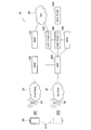
- FIG. 1 is an overall schematic configuration diagram of a wireless communication system 10.
- FIG. 2 is a functional block configuration diagram of UE50.
- FIG. 3 is a functional block configuration diagram of the SMF / PGW-C300.
- FIG. 4 is a diagram illustrating a schematic sequence of inter-system handover from 4G to 5G by the UE 50.
- FIG. 5 is a diagram illustrating a configuration example of an EPS bearer and a QoS flow.
- FIG. 6 is a diagram illustrating a sequence example in the handover preparation phase.
- FIG. 7 is a diagram illustrating a sequence example in the handover execution phase.
- FIG. 8 is a diagram illustrating a sequence example when the UE 50 sets a 5GC and a PDU session.
- FIG. 9 is a diagram illustrating an operation example of the UE 50 based on the mapping model.
- FIG. 10 is a diagram illustrating an example of a hardware configuration of the UE 50 and the SMF / PGW-C
- FIG. 1 is an overall schematic configuration diagram of a radio communication system 10 according to the present embodiment.
- the wireless communication system 10 supports a plurality of wireless communication methods.
- the radio communication system 10 includes a plurality of radio communication systems with different radio communication schemes.
- the wireless communication system 10 includes a wireless communication system (first wireless communication system) according to 4G, a wireless communication system (second wireless communication system) according to 5G, Consists of.
- 4G is a wireless communication system in accordance with Long Term Evolution (LTE), Evolved Universal Terrestrial Radio Access Network 20 (hereinafter referred to as E-UTRAN20), Mobility Management Entity 100 (hereinafter referred to as MME100), and Serving Gateway 150 ( The following includes SGW150).
- LTE Long Term Evolution
- E-UTRAN20 Evolved Universal Terrestrial Radio Access Network 20
- MME100 Mobility Management Entity 100
- SGW150 Serving Gateway 150
- 5G is a successor system of LTE called New Radio (NR), etc.
- 5G Radio Access Network 30 hereinafter 5G RAN30
- AMF200 Access and Mobility Management Function 200
- SMF / PGW-C300 Session Management Function / PDN Gateway -C plane 300
- UPF / PGW-U400 User Plane Function ⁇ 400
- UDM500 Unified Data Management 500
- PCF / PCRF600 Policy Control Function / Policy and Charging Rules Function 600
- DN40 ⁇ Data Network 40
- SGW150 SGW150
- UPF / PGW-U400 UPF / PGW-U400
- IP network such as the Internet
- FIG. 1 only nodes (devices) related to the present invention are shown.
- SMF / PGW-C300, UPF / PGW-U400, and PCF / PCRF600 will be expanded as 4G functions (PGW-C, PGW-U, PCRF) in the future. This is described in this way.
- 4G may be referred to as LTE (including LTE-Advanced), and “5G” may be referred to as New Radio (NR) or the like.
- NR New Radio
- a node group on the 4G core network side excluding E-UTRAN 20 may be called EvolvedvolvePacket Core (EPC).
- EPC EvolvedvolvePacket Core
- 5GC 5G Core
- E-UTRAN20 includes a radio base station 25.
- the radio base station 25 may be referred to as eNB (eNode B).
- the 5G RAN30 includes a radio base station 35.
- the radio base station 35 may be referred to as gNB (gNode B).
- UE50 User device 50
- UE50 is compatible with 4G and 5G. That is, the UE 50 executes radio communication according to the radio base stations 25 and 4G, and also executes radio communication according to the radio base stations 35 and 5G.
- the UE 50 executes a handover between 4G (first radio communication system) and 5G (second radio communication system). That is, the UE 50 can execute a handover from 4G to 5G and a handover from 5G to 4G.
- 4G first radio communication system
- 5G second radio communication system
- the UE 50, EPC, and 5GC specify the bearer identifier (EPS BearerearID) that identifies the type of EPS bearer set in 4G and the type of QoS flow set in 5G.
- EPS BearerearID the bearer identifier
- QoS Flow ID the identified flow identifier
- the association between the EPS bearer and the QoS flow is acquired, and a handover is performed between the bearer and the QoS flow associated with each other To do.
- EPS Bearer ID is abbreviated as EBI
- QoS FlowID is abbreviated as QFI, as appropriate.
- FIG. 2 is a functional block configuration diagram of UE50.
- the UE 50 includes a radio communication unit 51, a connection setting unit 53, a session setting unit 55, a mapping information holding unit 57, and a handover execution unit 59.
- the wireless communication unit 51 performs wireless communication according to 4G and 5G. Specifically, the radio communication unit 51 transmits and receives radio signals according to 4G with the radio base stations 25. The wireless communication unit 51 transmits and receives wireless signals according to the wireless base stations 35 and 5G.
- the type of UE 50 is not particularly limited.
- UE50 may belong to the normal UE category, or a category for Internet of Things (IoT), specifically, a category for bandwidth reduced low complexity UE (BL UE) (category M1, M2) You may belong to it.
- IoT Internet of Things
- BL UE bandwidth reduced low complexity UE
- the UE 50 may be able to perform carrier aggregation (CA) and dual connectivity (DC).
- CA carrier aggregation
- DC dual connectivity
- the connection setting unit 53 sets EPC and Packet Data Network connection (PDN connection). Specifically, the connection setting unit 53 sets a PDN connection via an EPS bearer that is a logical communication path set as EPC. That is, the PDN connection is associated with (associated with) the EPS bearer.
- PDN connection Packet Data Network connection
- Session setting unit 55 sets 5GC and Protocol Data Unit session (PDU session). Specifically, the session setting unit 55 sets a PDU session indicating a connection relationship (association) between the UE 50 and the DN 40 that provides the PDN connectivity connectivity service.
- PDU session 5GC and Protocol Data Unit session
- the PDU session is related (associated) with the QoS flow (5G QoS Flow) specified in 5GC.
- the QoS flow corresponds to a specific quality of service (QoS), and the communication (traffic) assigned to the QoS flow is determined by scheduling, queue management, shaping, radio link control layer (RLC) configuration, etc. Receive the same treatment.
- QoS quality of service
- RLC radio link control layer
- the mapping information holding unit 57 holds mapping information (corresponding information) in which the EPS bearer type and the QoS flow (5G (QoS Flow) type are mapped.
- mapping information corresponding information
- the EPS bearer is set in 4G.
- the QoS flow is set by 5G and is defined according to a specific quality of service.
- This mapping information is required when the UE 50 performs handover (inter-system handover) between 4G and 5G. That is, when the UE 50 performs the inter-system handover, it is necessary to map the EPS bearer related to the PDN connection and the QoS flow related to the PDU session.
- the EPS Bearer ID that identifies the type of EPS bearer is associated with the Bearer Rule that includes the QoS Profile. Further, a QoS Flow ID (QFI) for identifying the type of QoS flow is associated with a QoS Rule including a QoS Profile (see FIG. 5).
- QFI QoS Flow ID
- the mapping information held by the mapping information holding unit 57 indicates the association between such EPS Bearer ID and QoS Flow ID. That is, in the mapping information, EPS Bearer ID that identifies the type of EPS bearer and QoS Flow ID that identifies the QoS flow are mapped. Details of the Bearer rule and the QoS rule will be described later with reference to FIG.
- the mapping information holding unit 57 can hold the mapping information transmitted from the EPC or 5GC.
- the mapping information can be transmitted to the UE 50 by, for example, a radio resource control layer (RRC layer) message or broadcast information (SIB (System Information Block)).
- RRC layer radio resource control layer
- SIB System Information Block
- mapping information may be stored in advance in the Universal Integrated Circuit Card (UICC) or Universal Subscriber Identity Module (USIM) provided in the UE 50. Further, the mapping information may be updated when firmware is updated by FOTA (Firmware On-The-Air). Alternatively, the mapping information may be updated when the operating system of the UE 50 is updated.
- UICC Universal Integrated Circuit Card
- USB Universal Subscriber Identity Module
- the range of QoS Flow ID included in the mapping information held by the mapping information holding unit 57 may include a range used only for association with EPS Bearer ID. That is, a predetermined area may be reserved in the range of QoS Flow ID (for example, a range defined by numerical values or specific character symbols) in consideration of expansion of association. For example, the reserved predetermined area may not be used to allocate only the QoS flow in 5GC.
- the handover execution unit 59 executes the intra-system handover of the UE 50 and the inter-system handover of the UE 50.
- the handover executing unit 59 executes inter-system handover between 4G and 5G using the mapping information held by the mapping information holding unit 57.
- the handover execution unit 59 acquires the association between the EPS bearer set by the UE 50 and the QoS flow set by the UE 50 using the mapping information. . Furthermore, the handover execution unit 59 executes handover between the EPS bearer and the QoS flow that are associated with each other based on the acquired association.
- the handover execution unit 59 executes the handover according to the interwork procedure specified in 3GPP TS 23.502 Section 4.11 (System interworking procedures with EPS).
- the handover execution unit 59 performs correspondence between the acquired EPS bearer and the QoS flow until the QoS flow set with 5GC is released after executing the handover, that is, the inter-system handover between 4G and 5G. You may keep the date. Further, the SMF / PGW-C300 may hold such association until the QoS flow is released. As a result, the UE 50 and the SMF / PGW-C 300 can refer to the association between the EPS bearer and the QoS flow acquired quickly even when some necessity arises.
- FIG. 3 is a functional block configuration diagram of the SMF / PGW-C300.
- the SMF / PGW-C 300 includes a connection control unit 310, a session control unit 320, a mapping information holding unit 330, and a mapping information management unit 340.
- the connection control unit 310 executes control related to the PDN connection set with the UE 50. Specifically, the connection control unit 310 executes setting and releasing of a PDN connection in cooperation with other nodes (such as the MME 100 and the AMF 200) constituting the EPC or 5GC.
- other nodes such as the MME 100 and the AMF 200
- the session control unit 320 executes control related to the PDU session set with the UE 50. Specifically, the session control unit 320 executes setting and release of a PDU session in cooperation with other nodes (such as AMF 200) configuring the EPC or 5GC.
- other nodes such as AMF 200
- the mapping information holding unit 330 holds mapping information (corresponding information) similar to the mapping information held by the UE 50. That is, the mapping information holding unit 330 holds mapping information in which the EPS bearer type and the QoS flow type are mapped.
- mapping information holding unit 330 can hold the mapping information generated or updated by the mapping information management unit 340.
- the mapping information management unit 340 manages mapping information (corresponding information) in which the EPS bearer type and the QoS flow type are mapped. Specifically, the mapping information management unit 340 generates the mapping information based on information provided from other nodes constituting the EPC or 5GC. The specific mapping contents may be designated by the operator of the radio communication system 10, or may be automatically generated based on a predetermined algorithm.
- the mapping information management unit 340 can cause the mapping information holding unit 330 to hold the generated mapping information and transmit it to the UE 50. As described above, the mapping information can be transmitted to the UE 50 by an RRC layer message or broadcast information.
- mapping information management unit 340 can update the contents of the mapping information based on information provided from other nodes constituting the EPC or 5GC.
- the mapping information management unit 340 causes the mapping information holding unit 330 to hold the updated mapping information.
- the UE 50 maps the EPS Bearer ID that identifies the type of the EPS bearer and the mapping information in which the QoS flow is mapped, specifically, the mapping information that indicates the correspondence between the EPS Bearer ID and the QoS Flow ID. Holding. For this reason, it is not necessary to transmit the mapping information, that is, the association between the EPS Bearer ID and the QoS Flow ID, to the UE50 every time the UE50 executes the inter-system handover.
- FIG. 4 shows a schematic sequence of inter-system handover from 4G to 5G by UE50.
- the SMF / PGW-C300 generates mapping information based on a rule for associating EPS Bearer ID (EBI) and QoS Flow ID (QFI) defined in advance (S10).
- EBI EPS Bearer ID
- QFI QoS Flow ID
- the SMF / PGW-C300 can generate mapping information in advance regardless of the timing of handover between systems of the UE50.
- mapping information is provided to the UE 50 in advance and is also retained by the UE 50.
- the mapping information can be provided to the UE 50 by using broadcast information or a method of preinstalling in UICC / USIM or the like.
- the SMF / PGW-C300 transmits N2 SM Information to the AMF 200 (S20).
- the processing after S20 is the same as the existing inter-system handover sequence from 4G to 5G.
- the AMF 200 transmits / receives a handover request and response (N2 HO req./res.) With the 5G RAN30 based on the N2 SM Information received from the SMF / PGW-C300 (S30). Further, the AMF 200 transmits Nx Relocation Response indicating that the UE 50 transitions from 4G to 5G to the MME 100 (S40).
- MME100 which received NxNRelocation Response sends HO command to UE50 via E-UTRAN20 (S50, S60).
- the UE 50 executes handover to 5G RAN 30 based on the received HO command (S70).
- the UE 50 determines the QFI associated with the EBI of the EPS bearer that is being set, that is, in an active state, using the mapping information that is held.
- UE50 sets the radio bearer with 5G RAN30 using the QoS flow corresponding to the determined QFI (S80).
- FIG. 5 shows a configuration example of EPS bearer and QoS flow. Specifically, FIG. 5 shows an EPS bearer used in EPC and a QoS flow session parameter used in 5GC.
- FIG. 5 shows a rule set of quality of service (QoS) and a bearer necessary for setting a session in 5GC and a connection in EPC, and a configuration content thereof.
- QoS quality of service
- the set of QoS rules (QoS Profile) in 5GC is used when setting the QoS flow.
- Each QoS flow is managed by assigning an ID (QFI) to each QoS flow.
- QFI ID
- the rule set for bearers in EPC is the same as 5GC, and is used when setting up a PDN connection.
- Each bearer rule (Bearer Rule) set is managed by assigning an EPS Bearer ID (EBI).
- EBI EPS Bearer ID
- a 5GC PDU session can contain multiple QoS flows identified by QFI.
- a typical configuration is such that a single PDU session is set up for the Internet, and a plurality of QoS flows with different QoS depending on applications such as real-time voice, data communication, and mail are included in the PDU session. .
- a PDN connection is defined by the name of a default EPS bearer (such as EPS Bearer 1), not a unique ID. Therefore, when a plurality of different QoS flows are required in EPC, a plurality of EPS Bearer IDs (EBI) are prepared, and the plurality of EBIs are tied to a default EPS bearer (such as EPS bearer 1).
- EBI EPS Bearer IDs
- EBI for example, EPS Bearer 1 in the figure
- QoS profile includes QoS class identifier (QCI) and QoS parameters.
- QCI QoS class identifier
- QFI for example, QFI 1 in the figure
- QoS rule including a QoS profile.
- the QoS profile includes a 5G QoS indicator (5QI) and QoS parameters.
- Mapping information is composed of multiple correspondences between EBI and QFI. That is, in the mapping information, the EPS bearer type and the QoS flow type are mapped.
- FIG. 6 shows a sequence example in the handover preparation phase.
- FIG. 7 shows a sequence example in the handover execution phase.
- FIGS. 6 and 7 are shown in 3GPP TS 23.502 Section 4.11 (System interworking procedures with EPS).
- the sequence examples shown in FIGS. 6 and 7 are shown in the above-described prior art document (S2-171013).
- S2-171013 prior art document
- the SMF / PGW-C 300 in the handover preparation phase, the SMF / PGW-C 300 generates an ID of the PDU session and assigns a predetermined QoS flow (step 8 in FIG. 6). At this time, the SMF / PGW-C300 uses mapping information generated in advance.
- the ID of the PDU session is substantially associated with the default EBI of the PDN connection.
- the QFI is associated with any EBI.
- the UE 50 executes the association between the EBI and the QFI using the same mapping information as the mapping information used by the SMF / PGW-C300 (FIG. 7). Step 3).
- mapping information held in advance is used, in the handover preparation phase (specifically, step 15) and the handover execution phase (specifically, steps 1 and 2), Mapping information is not sent or received.
- mapping information held by the UE 50 and the SMF / PGW-C300 can be updated, but the updated mapping information of the OAM (Operation, Administration, Management) system on the network (EPC, 5GC) side is updated to the UE50. And may be provided to nodes such as SMF / PGW-C300.
- OAM Operaation, Administration, Management
- FIG. 8 shows a sequence example when UE 50 sets 5GC and PDU session. Specifically, FIG. 8 shows a sequence example when UE 50 first resides in LTE / EPC (idle mode) and then moves to 5 GC in this state to set up 5GC and PDU session. Indicates. That is, the UE 50 may set a PDU session in the core network (5GC) even in an idle state.
- LTE / EPC extranet control
- the UE 50 executes a PDU session setting procedure in order to attach to the 5GC.
- UE50 performs registration to 5GC, and then executes the PDU session setup procedure to establish all PDN connections. It is described that it moves to 5GC.
- differences from the existing PDU session setting procedure will be mainly described.
- UE 50 transmits a PDU session setting request to AMF 200 (step 1 in FIG. 8).
- UE50 since UE50 was originally located in EPC, it has EBI of the default EPS bearer.
- the UE 50 uses the mapping information held by the UE 50 to derive the ID of the PDU session in 5GC that is associated with the EBI of the default EPS bearer, and the ID of the PDU session (see FIG. 5, QFI and A request to set up a PDU session including (to be linked) is sent to the AMF 200.
- SMF / PGW-C300 acquires QFI matched with EBI using the mapping information similar to the mapping information which UE50 used (step 10 of FIG. 8).
- the SMF / PGW-C300 notifies only the acquired QFI to the AMF 200 by PDU Session Establishment Accept.
- the UE 50 obtains the QFI included in PDU Session Establishment Accept (Step 12 in FIG. 8). The UE 50 determines the association between the EBI and the QFI using the held mapping information. After that, the UE 50 sets up a 5GC and a PDU session and executes a handover.
- mapping Model Next, a mapping model that can be applied when mapping information is generated will be described.
- the mapping information described above can be used for 4G to 5G handover and 5G to 4G handover.
- QFI is mapped to EBI.
- the QFI associated with the QoS flow set in 5GC may be randomly mapped, that is, the QFI specific to the QoS flow may be mapped to the EBI at each handover timing.
- the QFI may be associated with the QoS flow when the QoS flow is generated, or may be associated with the QoS flow in the handover procedure.
- Model 1 In this model, UE50 and 5GC (SMF / PGW-C300 etc.) map QFI (native QFI) peculiar to QoS flow generated in 5GC at the time of 4G to 5G handover (transition).
- QFI native QFI
- UE 50 and 5GC continue to hold QFI information mapped to the QoS flow until the QoS flow is released. For this reason, by securing a specific QFI area as the QFI value usage range in this way, when a handover occurs again, the specific EBI and QFI during the corresponding PDU session exist. Can be reused.
- the QFI mapped to a specific EBI may be changed when the UE 50 is handed over from 5G to 4G and then returned to 5G. Even in this model, it is preferable to secure such a unique QFI area as the QFI range.
- the region can be reused for a PDU session generated in the 5GC. Further, when the UE 50 performs a handover from 5G to 4G, the UE 50 can determine the EPS bearer to be used based on the EBI associated with the QFI.
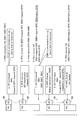
- FIG. 9 shows an operation example of the UE 50 based on the above-described mapping model. Specifically, FIG. 9 mainly shows the change in the association between the QFI and the EBI when the UE 50 executes a 4G to 5G handover.
- EBI1 to 5 indicate an example of EPS Bearer ID set by EPC
- QFI1 to 5 indicate an example of QoS Flow ID set by 5GC.
- UE 50 attached to 4G sets a PDN connection
- EBI1 to EBI3 are associated with the PDN connection, that is, three types of EPS bearers are set. (Step 1).
- UE 50 executes a handover to 5G by transmitting / receiving an RRC layer message or the like with the EPC (hereinafter the same), and sets up a PDU session (steps 2 to 4). Specifically, the UE 50 acquires QFI1 and 2 associated with EBI1 and 2 based on the mapping information held.
- the QoS flow corresponding to QFI3 cannot be set due to lack of resources, and is deactivated.
- QFI4 and 5 that are unique QFI are added to the QoS flow generated in 5GC, and EBI4 and 5 are associated with QFI4 and 5, respectively (step 5).
- the UE 50 resets the content of the PDU session based on the added QoS flow (step 6).
- UE50 executes a handover to 4G (Steps 7 and 8).
- EBI5 a PDN connection is set based only on the association between QFI1, 2, 4 and EBI1, 2, 4 due to lack of resources. For this reason, the PDN connection corresponding to EBI5 cannot be set and is deactivated.
- the UE 50 executes the handover to 5G again (Steps 9 and 10).
- the UE 50 may determine that the QFI 4 corresponds to any EBI based on the mapping information or as the native QFI. If QFI5 exists as mapping information or native QFI, a QoS flow corresponding to QFI5 cannot be set and is deactivated.
- UE50 can use native QFI in the case of model 1 described above, and mapped QFI in the case of model 2. Further, as shown in Step 10, even if the UE 50 executes a handover to 5G, it is not necessary to delete a NAS (Non-Access Stratum) layer.
- NAS Non-Access Stratum
- UE50 holds the correspondence between QFI1, 2, 4 and EBI1,2,4 (QFI4 is native).
- the following action / effect can be obtained.
- the UE 50 and the SMF / PGW-C 300 hold in advance mapping information in which the EPS bearer type and the QoS flow type are mapped prior to the inter-system handover.
- UE50 and SMF / PGW-C300 use the mapping information to acquire the association between EPS bearer (specifically, EBI) and QoS flow (specifically, QFI) during inter-system handover. Then, inter-system handover is executed based on the association.
- EBI EPS bearer
- QoS flow specifically, QFI
- the method of notifying the UE 50 of the mapping information every time the UE 50 executes the inter-system handover is simple, but may cause an increase in the amount of signaling and a delay associated with the transmission / reception of the mapping information at the time of handover.
- the frequency at which the mapping information needs to be updated is not high, and the transmission timing of the mapping information is not directly related to the timing at which the UE 50 executes the inter-system handover.
- the association (definition) between a specific type of EPS bearer and a specific type of QoS flow is required only when a new service is defined.
- mapping information is held in advance in the UE 50 and the SMF / PGW-C300 without regard to the timing of executing the inter-system handover.
- mapping information in 4G there is no need to notify the UE 50 of the N1 SM Container including the mapping information from the EPC using the HO command. This eliminates the need for modification (addition of functions) to notify mapping information in 4G.
- the range of QFI included in the mapping information may include a range used only for association with EBI. That is, a predetermined area may be reserved in the QFI range (for example, a range defined by a numerical value or a specific character symbol) in consideration of expansion of association. Thereby, it is possible to flexibly cope with QFI (native QFI) specific to the QoS flow generated in 5GC and future expansion.
- the association between the acquired EPS bearer and the QoS flow may be held after the inter-system handover is executed until the QoS flow set as 5GC is released.
- the SMF / PGW-C300 generates and holds the mapping information.
- the mapping information may be other nodes that configure the 5GC (for example, AMF200) or other EPC.
- a node eg, MME 100
- MME 100 may perform either or both of generation and maintenance.
- each functional block may be realized by one device physically and / or logically coupled, and two or more devices physically and / or logically separated may be directly and / or indirectly. (For example, wired and / or wireless) and may be realized by the plurality of devices.
- FIG. 10 is a diagram illustrating an example of a hardware configuration of the apparatus.
- the apparatus may be configured as a computer apparatus including a processor 1001, a memory 1002, a storage 1003, a communication apparatus 1004, an input apparatus 1005, an output apparatus 1006, a bus 1007, and the like.
- Each functional block (see FIGS. 2 and 3) of the device is realized by any hardware element of the computer device or a combination of the hardware elements.
- the processor 1001 controls the entire computer by operating an operating system, for example.
- the processor 1001 may be configured by a central processing unit (CPU) including an interface with peripheral devices, a control device, an arithmetic device, a register, and the like.
- CPU central processing unit
- the memory 1002 is a computer-readable recording medium and includes, for example, at least one of ROM (Read Only Memory), EPROM (Erasable Programmable ROM), EEPROM (Electrically Erasable Programmable ROM), RAM (Random Access Memory), and the like. May be.
- the memory 1002 may be called a register, a cache, a main memory (main storage device), or the like.
- the memory 1002 can store a program (program code) that can execute the method according to the above-described embodiment, a software module, and the like.
- the storage 1003 is a computer-readable recording medium such as an optical disc such as a CD-ROM (Compact Disc ROM), a hard disk drive, a flexible disc, a magneto-optical disc (eg a compact disc, a digital versatile disc, a Blu-ray). (Registered trademark) disk, smart card, flash memory (for example, card, stick, key drive), floppy (registered trademark) disk, magnetic strip, and the like.
- the storage 1003 may be referred to as an auxiliary storage device.
- the recording medium described above may be, for example, a database including a memory 1002 and / or a storage 1003, a server, or other suitable medium.
- the communication device 1004 is hardware (transmission / reception device) for performing communication between computers via a wired and / or wireless network, and is also referred to as a network device, a network controller, a network card, a communication module, or the like.
- the input device 1005 is an input device (for example, a keyboard, a mouse, a microphone, a switch, a button, a sensor, etc.) that accepts an input from the outside.
- the output device 1006 is an output device (for example, a display, a speaker, an LED lamp, or the like) that performs output to the outside. Note that the input device 1005 and the output device 1006 may have an integrated configuration (for example, a touch panel).
- each device such as the processor 1001 and the memory 1002 is connected by a bus 1007 for communicating information.
- the bus 1007 may be configured with a single bus or may be configured with different buses between apparatuses.
- notification of information includes physical layer signaling (eg, DCI (Downlink Control Information), UCI (Uplink Control Information)), upper layer signaling (eg, RRC signaling, MAC (Medium Access Control) signaling, broadcast information (MIB ( Master (Information Block), SIB (System Information Block)), other signals, or combinations thereof, and RRC signaling may also be referred to as RRC messages, eg, RRC Connection Connection message, RRC It may be a Connection ⁇ ⁇ Reconfiguration message.
- RRC messages eg, RRC Connection Connection message, RRC It may be a Connection ⁇ ⁇ Reconfiguration message.
- input / output information may be stored in a specific location (for example, a memory) or may be managed by a management table.
- the input / output information can be overwritten, updated, or appended.
- the output information may be deleted.
- the input information may be transmitted to other devices.
- the specific operation performed by the SMF / PGW-C300 may be performed by another network node (device). Further, the SMF / PGW-C300 function may be provided by a combination of a plurality of other network nodes.
- a channel and / or symbol may be a signal (signal) if there is a corresponding description.
- the signal may be a message.
- system and “network” may be used interchangeably.
- the parameter or the like may be represented by an absolute value, may be represented by a relative value from a predetermined value, or may be represented by other corresponding information.
- the radio resource may be indicated by an index.
- the radio base station 25 and 35 can accommodate one or a plurality of (for example, three) cells (also called sectors).
- a base station accommodates multiple cells, the entire coverage area of the base station can be partitioned into multiple smaller areas, each smaller area being a base station subsystem (eg, indoor small base station RRH: Remote Radio Head) can also provide communication services.
- RRH Remote Radio Head
- cell refers to part or all of the coverage area of a base station and / or base station subsystem that provides communication services in this coverage.
- base station eNodeB
- gNB gNodeB
- a base station may also be referred to in terms such as a fixed station, NodeB, eNodeB (eNB), gNodeB (gNB), access point, femtocell, small cell, and the like.
- the AMF 200 is a subscriber station, mobile unit, subscriber unit, wireless unit, remote unit, mobile device, wireless device, wireless communication device, remote device, mobile subscriber station, access terminal, mobile terminal, wireless terminal by those skilled in the art. , Remote terminal, handset, user agent, mobile client, client, or some other appropriate terminology.
- the phrase “based on” does not mean “based only on”, unless expressly specified otherwise. In other words, the phrase “based on” means both “based only on” and “based at least on.”
- any reference to elements using designations such as “first”, “second”, etc. as used herein does not generally limit the amount or order of those elements. These designations can be used herein as a convenient way to distinguish between two or more elements. Thus, a reference to the first and second elements does not mean that only two elements can be employed there, or that in some way the first element must precede the second element.
- the above-described user apparatus, wireless communication system, and wireless communication method are useful because a rapid handover between 4G and 5G can be realized while avoiding the modification of existing 4G.
- Wireless communication system 20 E-UTRAN 25 Radio base station 30 5G RAN 35 Radio base station 40 DN 50 UE 51 Wireless communication unit 53 Connection setting unit 55 Session setting unit 57 Mapping information holding unit 59 Handover execution unit 100 MME 150 SGW 200 AMF 300 SMF / PGW-C 310 Connection control unit 320 Session control unit 330 Mapping information holding unit 340 Mapping information management unit 400 UPF / PGW-U 500 UDM 600 PCF / PCRF
Landscapes
- Engineering & Computer Science (AREA)
- Computer Networks & Wireless Communication (AREA)
- Signal Processing (AREA)
- Mobile Radio Communication Systems (AREA)
Abstract
La présente invention concerne un UE (50) pourvu : d'une unité de rétention d'informations de mappage (57) qui contient des informations de correspondance dans lesquelles le type d'un support EPS établi dans un système 4G est mis en corrélation avec le type d'un flux QoS qui est établi dans un système 5G de manière à correspondre à la qualité de service ; et d'une unité d'exécution de transfert (59) qui, à l'aide desdites informations de correspondance, acquiert la corrélation entre le support EPS établi par l'UE (50) et le flux QoS établi par l'UE (50) et exécute un transfert entre le support EPS et le flux QoS mutuellement corrélés.
Priority Applications (4)
| Application Number | Priority Date | Filing Date | Title |
|---|---|---|---|
| US16/610,354 US11445420B2 (en) | 2017-05-02 | 2018-05-02 | User device, radio communication system, and radio communication method |
| CN201880029247.2A CN110651499B (zh) | 2017-05-02 | 2018-05-02 | 用户装置、无线通信系统以及无线通信方法 |
| EP18794861.7A EP3614740A4 (fr) | 2017-05-02 | 2018-05-02 | Équipement utilisateur, système de communication sans fil et procédé de communication sans fil |
| JP2019515747A JP6998943B2 (ja) | 2017-05-02 | 2018-05-02 | ユーザ装置、無線通信システム及び無線通信方法 |
Applications Claiming Priority (2)
| Application Number | Priority Date | Filing Date | Title |
|---|---|---|---|
| JP2017-091727 | 2017-05-02 | ||
| JP2017091727 | 2017-05-02 |
Publications (1)
| Publication Number | Publication Date |
|---|---|
| WO2018203569A1 true WO2018203569A1 (fr) | 2018-11-08 |
Family
ID=64016087
Family Applications (1)
| Application Number | Title | Priority Date | Filing Date |
|---|---|---|---|
| PCT/JP2018/017521 Ceased WO2018203569A1 (fr) | 2017-05-02 | 2018-05-02 | Équipement utilisateur, système de communication sans fil et procédé de communication sans fil |
Country Status (5)
| Country | Link |
|---|---|
| US (1) | US11445420B2 (fr) |
| EP (1) | EP3614740A4 (fr) |
| JP (1) | JP6998943B2 (fr) |
| CN (1) | CN110651499B (fr) |
| WO (1) | WO2018203569A1 (fr) |
Cited By (1)
| Publication number | Priority date | Publication date | Assignee | Title |
|---|---|---|---|---|
| JP7837631B1 (ja) * | 2025-10-15 | 2026-03-31 | 株式会社リンクスエンタテインメント | 車両遠隔制御システム及び車両遠隔制御装置 |
Families Citing this family (7)
| Publication number | Priority date | Publication date | Assignee | Title |
|---|---|---|---|---|
| EP3580959B1 (fr) * | 2017-02-07 | 2021-01-06 | Telefonaktiebolaget LM Ericsson (PUBL) | Traduction de porteuse |
| KR102334728B1 (ko) * | 2017-05-08 | 2021-12-02 | 후아웨이 테크놀러지 컴퍼니 리미티드 | 통신 시스템 간 이동 방법 및 장치 |
| CN109005565B (zh) * | 2017-06-06 | 2022-11-04 | 大唐移动通信设备有限公司 | 一种会话管理方法和装置 |
| EP3934324B1 (fr) * | 2017-06-15 | 2023-10-04 | Datang Mobile Communications Equipment Co., Ltd. | Méthode de transfert de données effectuée par smf et dispositif smf |
| KR102329925B1 (ko) * | 2017-08-14 | 2021-11-23 | 삼성전자 주식회사 | 4g/5g 동시 등록된 이동 통신 단말을 위한 네트워크 이동시 데이터 동기화 제공 방안 |
| US12185393B2 (en) * | 2018-09-19 | 2024-12-31 | Qualcomm Incorporated | Multicast idle mode behavior and paging |
| US20220124838A1 (en) * | 2020-10-19 | 2022-04-21 | Mediatek Inc. | Ma pdu session and user plane resource establishment for data transmission |
Citations (1)
| Publication number | Priority date | Publication date | Assignee | Title |
|---|---|---|---|---|
| JP2013535157A (ja) * | 2010-06-21 | 2013-09-09 | クゥアルコム・インコーポレイテッド | ワイヤレス通信システムにおける無線アクセス技術間ハンドオーバ中のQoSコンテキスト転送のための方法および装置 |
Family Cites Families (5)
| Publication number | Priority date | Publication date | Assignee | Title |
|---|---|---|---|---|
| JP5944004B2 (ja) * | 2011-10-03 | 2016-07-05 | インテル・コーポレーション | デバイスツーデバイス通信(d2d通信)メカニズム |
| EP3132622B1 (fr) * | 2014-04-15 | 2019-09-25 | Nokia Solutions and Networks Oy | Interfonctionnement avec un système à base de porteur |
| KR102115218B1 (ko) * | 2016-09-19 | 2020-05-26 | 에스케이텔레콤 주식회사 | 기지국장치 및 단말장치와, QoS 제어방법 |
| EP3580959B1 (fr) * | 2017-02-07 | 2021-01-06 | Telefonaktiebolaget LM Ericsson (PUBL) | Traduction de porteuse |
| US11889579B2 (en) * | 2017-03-24 | 2024-01-30 | Telefonaktiebolaget Lm Ericsson (Publ) | QoS flows inactivity counters |
-
2018
- 2018-05-02 US US16/610,354 patent/US11445420B2/en active Active
- 2018-05-02 WO PCT/JP2018/017521 patent/WO2018203569A1/fr not_active Ceased
- 2018-05-02 CN CN201880029247.2A patent/CN110651499B/zh active Active
- 2018-05-02 EP EP18794861.7A patent/EP3614740A4/fr not_active Ceased
- 2018-05-02 JP JP2019515747A patent/JP6998943B2/ja active Active
Patent Citations (1)
| Publication number | Priority date | Publication date | Assignee | Title |
|---|---|---|---|---|
| JP2013535157A (ja) * | 2010-06-21 | 2013-09-09 | クゥアルコム・インコーポレイテッド | ワイヤレス通信システムにおける無線アクセス技術間ハンドオーバ中のQoSコンテキスト転送のための方法および装置 |
Non-Patent Citations (3)
| Title |
|---|
| "TS 23.502: P-CR for Single Registration-based Interworking from EPS to 5GS procedure", SA WG2 MEETING #119, 3GPP, February 2017 (2017-02-01), pages 2 - 171013 |
| NTT DOCOMO: "TS 23.502: Nx-based Handover procedure", 3GPP TSG SA WG2 #119 S 2-171503, 17 February 2017 (2017-02-17), XP051234505 * |
| See also references of EP3614740A4 |
Cited By (1)
| Publication number | Priority date | Publication date | Assignee | Title |
|---|---|---|---|---|
| JP7837631B1 (ja) * | 2025-10-15 | 2026-03-31 | 株式会社リンクスエンタテインメント | 車両遠隔制御システム及び車両遠隔制御装置 |
Also Published As
| Publication number | Publication date |
|---|---|
| US20200092780A1 (en) | 2020-03-19 |
| JPWO2018203569A1 (ja) | 2020-03-12 |
| EP3614740A1 (fr) | 2020-02-26 |
| CN110651499B (zh) | 2022-07-12 |
| JP6998943B2 (ja) | 2022-01-18 |
| CN110651499A (zh) | 2020-01-03 |
| US11445420B2 (en) | 2022-09-13 |
| EP3614740A4 (fr) | 2020-02-26 |
Similar Documents
| Publication | Publication Date | Title |
|---|---|---|
| US11375396B2 (en) | Session management method, interworking method, and network apparatus | |
| JP7238916B2 (ja) | ネットワーク装置によって実行される方法、及びエッジサーバによって実行される方法 | |
| JP6998943B2 (ja) | ユーザ装置、無線通信システム及び無線通信方法 | |
| CN113767672B (zh) | 用于在插入中间会话管理功能之后管理无线通信的移动通信核心网络装置及方法 | |
| CN113507736B (zh) | 无线接入网节点、无线终端、核心网节点及其方法 | |
| JP7113124B2 (ja) | ネットワーク装置及び無線通信方法 | |
| CN108605269B (zh) | 一种会话管理方法及装置 | |
| US10021643B2 (en) | User plane IDLE mode buffering within software defined network architecture | |
| CN110999440B (zh) | 无线基站及无线通信方法 | |
| WO2018066702A1 (fr) | Système de communication sans fil, dispositif de réseau et procédé de communication sans fil | |
| CN110754116B (zh) | 用户装置、无线通信系统及无线通信方法 | |
| CN110022581A (zh) | 一种支持网络承载控制的方法、装置、网络单元及终端 | |
| JP6754900B2 (ja) | 無線通信システム、ユーザ装置、無線基地局及び無線通信方法 | |
| WO2017166291A1 (fr) | Procédé de communication, terminal, station de base, et équipement de gestion de mobilité | |
| US12621732B2 (en) | User device, radio communication system, and radio communication method | |
| JP2019033432A (ja) | 移動管理エンティティ及び無線通信方法 | |
| WO2017128048A1 (fr) | Procédé de notification, appareil de notification et système | |
| WO2014089835A1 (fr) | Procédé de gestion de porteuses, appareil, et système |
Legal Events
| Date | Code | Title | Description |
|---|---|---|---|
| 121 | Ep: the epo has been informed by wipo that ep was designated in this application |
Ref document number: 18794861 Country of ref document: EP Kind code of ref document: A1 |
|
| ENP | Entry into the national phase |
Ref document number: 2019515747 Country of ref document: JP Kind code of ref document: A |
|
| NENP | Non-entry into the national phase |
Ref country code: DE |
|
| ENP | Entry into the national phase |
Ref document number: 2018794861 Country of ref document: EP Effective date: 20191120 |