WO2018207398A1 - タイヤ - Google Patents
タイヤ Download PDFInfo
- Publication number
- WO2018207398A1 WO2018207398A1 PCT/JP2017/045597 JP2017045597W WO2018207398A1 WO 2018207398 A1 WO2018207398 A1 WO 2018207398A1 JP 2017045597 W JP2017045597 W JP 2017045597W WO 2018207398 A1 WO2018207398 A1 WO 2018207398A1
- Authority
- WO
- WIPO (PCT)
- Prior art keywords
- tire
- elastomer
- resin composition
- mass
- polyamide resin
- Prior art date
- Legal status (The legal status is an assumption and is not a legal conclusion. Google has not performed a legal analysis and makes no representation as to the accuracy of the status listed.)
- Ceased
Links
Images
Classifications
-
- B—PERFORMING OPERATIONS; TRANSPORTING
- B60—VEHICLES IN GENERAL
- B60C—VEHICLE TYRES; TYRE INFLATION; TYRE CHANGING; CONNECTING VALVES TO INFLATABLE ELASTIC BODIES IN GENERAL; DEVICES OR ARRANGEMENTS RELATED TO TYRES
- B60C7/00—Non-inflatable or solid tyres
- B60C7/10—Non-inflatable or solid tyres characterised by means for increasing resiliency
- B60C7/14—Non-inflatable or solid tyres characterised by means for increasing resiliency using springs
- B60C7/16—Non-inflatable or solid tyres characterised by means for increasing resiliency using springs of helical or flat coil form
- B60C7/18—Non-inflatable or solid tyres characterised by means for increasing resiliency using springs of helical or flat coil form disposed radially relative to wheel axis
-
- B—PERFORMING OPERATIONS; TRANSPORTING
- B60—VEHICLES IN GENERAL
- B60C—VEHICLE TYRES; TYRE INFLATION; TYRE CHANGING; CONNECTING VALVES TO INFLATABLE ELASTIC BODIES IN GENERAL; DEVICES OR ARRANGEMENTS RELATED TO TYRES
- B60C1/00—Tyres characterised by the chemical composition or the physical arrangement or mixture of the composition
-
- B—PERFORMING OPERATIONS; TRANSPORTING
- B60—VEHICLES IN GENERAL
- B60C—VEHICLE TYRES; TYRE INFLATION; TYRE CHANGING; CONNECTING VALVES TO INFLATABLE ELASTIC BODIES IN GENERAL; DEVICES OR ARRANGEMENTS RELATED TO TYRES
- B60C7/00—Non-inflatable or solid tyres
-
- C—CHEMISTRY; METALLURGY
- C08—ORGANIC MACROMOLECULAR COMPOUNDS; THEIR PREPARATION OR CHEMICAL WORKING-UP; COMPOSITIONS BASED THEREON
- C08G—MACROMOLECULAR COMPOUNDS OBTAINED OTHERWISE THAN BY REACTIONS ONLY INVOLVING UNSATURATED CARBON-TO-CARBON BONDS
- C08G69/00—Macromolecular compounds obtained by reactions forming a carboxylic amide link in the main chain of the macromolecule
- C08G69/02—Polyamides derived from amino-carboxylic acids or from polyamines and polycarboxylic acids
- C08G69/26—Polyamides derived from amino-carboxylic acids or from polyamines and polycarboxylic acids derived from polyamines and polycarboxylic acids
-
- C—CHEMISTRY; METALLURGY
- C08—ORGANIC MACROMOLECULAR COMPOUNDS; THEIR PREPARATION OR CHEMICAL WORKING-UP; COMPOSITIONS BASED THEREON
- C08J—WORKING-UP; GENERAL PROCESSES OF COMPOUNDING; AFTER-TREATMENT NOT COVERED BY SUBCLASSES C08B, C08C, C08F, C08G or C08H
- C08J7/00—Chemical treatment or coating of shaped articles made of macromolecular substances
- C08J7/12—Chemical modification
-
- C—CHEMISTRY; METALLURGY
- C08—ORGANIC MACROMOLECULAR COMPOUNDS; THEIR PREPARATION OR CHEMICAL WORKING-UP; COMPOSITIONS BASED THEREON
- C08K—Use of inorganic or non-macromolecular organic substances as compounding ingredients
- C08K5/00—Use of organic ingredients
- C08K5/0008—Organic ingredients according to more than one of the "one dot" groups of C08K5/01 - C08K5/59
- C08K5/0016—Plasticisers
-
- C—CHEMISTRY; METALLURGY
- C08—ORGANIC MACROMOLECULAR COMPOUNDS; THEIR PREPARATION OR CHEMICAL WORKING-UP; COMPOSITIONS BASED THEREON
- C08K—Use of inorganic or non-macromolecular organic substances as compounding ingredients
- C08K5/00—Use of organic ingredients
- C08K5/36—Sulfur-, selenium-, or tellurium-containing compounds
- C08K5/43—Compounds containing sulfur bound to nitrogen
- C08K5/435—Sulfonamides
-
- C—CHEMISTRY; METALLURGY
- C08—ORGANIC MACROMOLECULAR COMPOUNDS; THEIR PREPARATION OR CHEMICAL WORKING-UP; COMPOSITIONS BASED THEREON
- C08L—COMPOSITIONS OF MACROMOLECULAR COMPOUNDS
- C08L21/00—Compositions of unspecified rubbers
-
- C—CHEMISTRY; METALLURGY
- C08—ORGANIC MACROMOLECULAR COMPOUNDS; THEIR PREPARATION OR CHEMICAL WORKING-UP; COMPOSITIONS BASED THEREON
- C08L—COMPOSITIONS OF MACROMOLECULAR COMPOUNDS
- C08L23/00—Compositions of homopolymers or copolymers of unsaturated aliphatic hydrocarbons having only one carbon-to-carbon double bond; Compositions of derivatives of such polymers
- C08L23/02—Compositions of homopolymers or copolymers of unsaturated aliphatic hydrocarbons having only one carbon-to-carbon double bond; Compositions of derivatives of such polymers not modified by chemical after-treatment
- C08L23/04—Homopolymers or copolymers of ethene
-
- C—CHEMISTRY; METALLURGY
- C08—ORGANIC MACROMOLECULAR COMPOUNDS; THEIR PREPARATION OR CHEMICAL WORKING-UP; COMPOSITIONS BASED THEREON
- C08L—COMPOSITIONS OF MACROMOLECULAR COMPOUNDS
- C08L23/00—Compositions of homopolymers or copolymers of unsaturated aliphatic hydrocarbons having only one carbon-to-carbon double bond; Compositions of derivatives of such polymers
- C08L23/02—Compositions of homopolymers or copolymers of unsaturated aliphatic hydrocarbons having only one carbon-to-carbon double bond; Compositions of derivatives of such polymers not modified by chemical after-treatment
- C08L23/04—Homopolymers or copolymers of ethene
- C08L23/08—Copolymers of ethene
- C08L23/0807—Copolymers of ethene with unsaturated hydrocarbons only containing four or more carbon atoms
- C08L23/0815—Copolymers of ethene with unsaturated hydrocarbons only containing four or more carbon atoms with aliphatic 1-olefins containing one carbon-to-carbon double bond
-
- C—CHEMISTRY; METALLURGY
- C08—ORGANIC MACROMOLECULAR COMPOUNDS; THEIR PREPARATION OR CHEMICAL WORKING-UP; COMPOSITIONS BASED THEREON
- C08L—COMPOSITIONS OF MACROMOLECULAR COMPOUNDS
- C08L23/00—Compositions of homopolymers or copolymers of unsaturated aliphatic hydrocarbons having only one carbon-to-carbon double bond; Compositions of derivatives of such polymers
- C08L23/02—Compositions of homopolymers or copolymers of unsaturated aliphatic hydrocarbons having only one carbon-to-carbon double bond; Compositions of derivatives of such polymers not modified by chemical after-treatment
- C08L23/10—Homopolymers or copolymers of propene
-
- C—CHEMISTRY; METALLURGY
- C08—ORGANIC MACROMOLECULAR COMPOUNDS; THEIR PREPARATION OR CHEMICAL WORKING-UP; COMPOSITIONS BASED THEREON
- C08L—COMPOSITIONS OF MACROMOLECULAR COMPOUNDS
- C08L23/00—Compositions of homopolymers or copolymers of unsaturated aliphatic hydrocarbons having only one carbon-to-carbon double bond; Compositions of derivatives of such polymers
- C08L23/02—Compositions of homopolymers or copolymers of unsaturated aliphatic hydrocarbons having only one carbon-to-carbon double bond; Compositions of derivatives of such polymers not modified by chemical after-treatment
- C08L23/18—Homopolymers or copolymers of hydrocarbons having four or more carbon atoms
- C08L23/20—Homopolymers or copolymers of hydrocarbons having four or more carbon atoms having four to nine carbon atoms
- C08L23/22—Copolymers of isobutene; Butyl rubber; Homopolymers or copolymers of other iso-olefins
-
- C—CHEMISTRY; METALLURGY
- C08—ORGANIC MACROMOLECULAR COMPOUNDS; THEIR PREPARATION OR CHEMICAL WORKING-UP; COMPOSITIONS BASED THEREON
- C08L—COMPOSITIONS OF MACROMOLECULAR COMPOUNDS
- C08L25/00—Compositions of, homopolymers or copolymers of compounds having one or more unsaturated aliphatic radicals, each having only one carbon-to-carbon double bond, and at least one being terminated by an aromatic carbocyclic ring; Compositions of derivatives of such polymers
- C08L25/02—Homopolymers or copolymers of hydrocarbons
- C08L25/04—Homopolymers or copolymers of styrene
- C08L25/08—Copolymers of styrene
-
- C—CHEMISTRY; METALLURGY
- C08—ORGANIC MACROMOLECULAR COMPOUNDS; THEIR PREPARATION OR CHEMICAL WORKING-UP; COMPOSITIONS BASED THEREON
- C08L—COMPOSITIONS OF MACROMOLECULAR COMPOUNDS
- C08L33/00—Compositions of homopolymers or copolymers of compounds having one or more unsaturated aliphatic radicals, each having only one carbon-to-carbon double bond, and only one being terminated by only one carboxyl radical, or of salts, anhydrides, esters, amides, imides or nitriles thereof; Compositions of derivatives of such polymers
- C08L33/04—Homopolymers or copolymers of esters
- C08L33/06—Homopolymers or copolymers of esters of esters containing only carbon, hydrogen and oxygen, which oxygen atoms are present only as part of the carboxyl radical
- C08L33/08—Homopolymers or copolymers of acrylic acid esters
-
- C—CHEMISTRY; METALLURGY
- C08—ORGANIC MACROMOLECULAR COMPOUNDS; THEIR PREPARATION OR CHEMICAL WORKING-UP; COMPOSITIONS BASED THEREON
- C08L—COMPOSITIONS OF MACROMOLECULAR COMPOUNDS
- C08L35/00—Compositions of homopolymers or copolymers of compounds having one or more unsaturated aliphatic radicals, each having only one carbon-to-carbon double bond, and at least one being terminated by a carboxyl radical, and containing at least one other carboxyl radical in the molecule, or of salts, anhydrides, esters, amides, imides or nitriles thereof; Compositions of derivatives of such polymers
-
- C—CHEMISTRY; METALLURGY
- C08—ORGANIC MACROMOLECULAR COMPOUNDS; THEIR PREPARATION OR CHEMICAL WORKING-UP; COMPOSITIONS BASED THEREON
- C08L—COMPOSITIONS OF MACROMOLECULAR COMPOUNDS
- C08L51/00—Compositions of graft polymers in which the grafted component is obtained by reactions only involving carbon-to-carbon unsaturated bonds; Compositions of derivatives of such polymers
- C08L51/04—Compositions of graft polymers in which the grafted component is obtained by reactions only involving carbon-to-carbon unsaturated bonds; Compositions of derivatives of such polymers grafted on to rubbers
-
- C—CHEMISTRY; METALLURGY
- C08—ORGANIC MACROMOLECULAR COMPOUNDS; THEIR PREPARATION OR CHEMICAL WORKING-UP; COMPOSITIONS BASED THEREON
- C08L—COMPOSITIONS OF MACROMOLECULAR COMPOUNDS
- C08L51/00—Compositions of graft polymers in which the grafted component is obtained by reactions only involving carbon-to-carbon unsaturated bonds; Compositions of derivatives of such polymers
- C08L51/06—Compositions of graft polymers in which the grafted component is obtained by reactions only involving carbon-to-carbon unsaturated bonds; Compositions of derivatives of such polymers grafted on to homopolymers or copolymers of aliphatic hydrocarbons containing only one carbon-to-carbon double bond
-
- C—CHEMISTRY; METALLURGY
- C08—ORGANIC MACROMOLECULAR COMPOUNDS; THEIR PREPARATION OR CHEMICAL WORKING-UP; COMPOSITIONS BASED THEREON
- C08L—COMPOSITIONS OF MACROMOLECULAR COMPOUNDS
- C08L77/00—Compositions of polyamides obtained by reactions forming a carboxylic amide link in the main chain; Compositions of derivatives of such polymers
- C08L77/06—Polyamides derived from polyamines and polycarboxylic acids
-
- B—PERFORMING OPERATIONS; TRANSPORTING
- B60—VEHICLES IN GENERAL
- B60C—VEHICLE TYRES; TYRE INFLATION; TYRE CHANGING; CONNECTING VALVES TO INFLATABLE ELASTIC BODIES IN GENERAL; DEVICES OR ARRANGEMENTS RELATED TO TYRES
- B60C7/00—Non-inflatable or solid tyres
- B60C2007/005—Non-inflatable or solid tyres made by casting, e.g. of polyurethane
Definitions
- the present invention relates to a tire.
- Polyamide resin is known as a resin excellent in processability, chemical resistance, heat resistance, etc., and these properties are used in various resin products such as injection molded products, extrusion molded products, and film.
- Patent Document 1 discloses a polyamide resin composition containing a polyamide resin and a modifying polymer having a functional group reactive with the polyamide resin, and the polyamide resin composition is used as a pneumatic tire. It is disclosed that it is used for resin products such as inner liners and hoses.
- a non-pneumatic tire in which a skeleton member is formed from a resin composition has been proposed as a tire that does not need to be filled with pressurized air.
- the effect of suppressing the crack growth is better as the dispersibility of the elastomer is better, but the dispersibility of the elastomer can be improved by general techniques such as strengthening the kneading conditions of the resin and elastomer and improving the modification rate of the elastomer.
- the melt viscosity of the resin composition containing the resin and the elastomer is remarkably increased.
- the resin composition is not sufficiently mixed at the junction (weld) of the resin composition flowing through the mold. The strength of the obtained skeleton member is reduced, leading to a decrease in durability.
- an object of the present invention is to solve the above-mentioned problems of the prior art and provide a highly durable tire using a resin composition.
- the gist configuration of the present invention for solving the above-described problems is as follows.
- the tire of the present invention contains a polyamide resin and an elastomer having a glass transition point of 25 ° C. or less,
- the melt viscosity ⁇ (Pa ⁇ sec) at 240 ° C. and the average inter-interface distance ⁇ ( ⁇ m) between elastomers are expressed by the following formula (1): ⁇ ⁇ 34.369 ⁇ -3.525 (1)
- a resin composition satisfying the above relationship is used.
- Such a tire of the present invention has high durability.
- the melt viscosity ⁇ at 240 ° C. of the resin composition was calculated with the attached software from the measurement result under a load of 2.16 kg using a capillary rheometer CFT-100D manufactured by Shimadzu Corporation. .
- the average inter-interface distance ⁇ between elastomers in the resin composition was calculated by the following method. First, three areas of 30 ⁇ m ⁇ 30 ⁇ m were confirmed with AFM, and the image measured with ImageJ was processed to determine the average particle diameter of the elastomer. At this time, 0.09 ⁇ m 2 or less was removed as noise. Thereafter, the distance between the interfaces when the elastomers having the average particle diameter calculated by the above method were arranged at equal intervals in a region of 30 ⁇ m ⁇ 30 ⁇ m was obtained, and this was defined as the average interfacial distance ⁇ between the elastomers.
- the polyamide resin is a polyamide resin obtained by polymerizing an aliphatic diamine having 6 to 20 carbon atoms and an aliphatic dicarboxylic acid having 10 to 20 carbon atoms. In this case, even if the tire is used in a high humidity environment, the tire can maintain high durability.
- the elastomer is polyethylene, polypropylene, ethylene-propylene rubber, ethylene-1-butene copolymer, poly ⁇ -olefin, acrylic rubber, and styrene-ethylene-butylene-styrene copolymer. It contains at least one selected from the group consisting of polymers. In this case, the durability of the tire can be further improved.
- maleic anhydride is copolymerized or grafted on at least a part of the elastomer. In this case, the durability of the tire can be further improved.
- an epoxy-terminated acrylic ester is copolymerized or grafted on at least a part of the elastomer. Also in this case, the durability of the tire can be further improved.
- the resin composition used in the tire of the present invention preferably contains 60 to 90% by mass of the polyamide resin, more preferably 65 to 85% by mass, and even more preferably 70 to 80% by mass. In this case, the durability of the tire can be further improved.
- 10 to 50% by mass of the elastomer is a modified elastomer, and 90 to 50% by mass of the elastomer is an unmodified elastomer.
- the durability of the tire can be further improved.
- the resin composition used in the tire of the present invention preferably further contains 1 to 20% by mass of a plasticizer.
- a plasticizer 1 to 20% by mass of a plasticizer.
- the plasticizer preferably contains at least one selected from the group consisting of N-butylbenzenesulfonamide, 2-ethylhexyl-4-hydroxybenzoate, and N- (2-hydroxypropyl) benzenesulfonamide. .
- the durability of the tire can be further improved.
- the elastomer preferably has a melt flow rate (MFR) of 15 g / 10 min or more under a load of 2.16 kg at 230 ° C.
- MFR melt flow rate
- the average inter-interface distance ⁇ between the elastomers in the resin composition is shortened, and the durability of the tire using it can be further improved.
- 60 to 90% by mass of the polyamide resin is polyamide 610 having a melt flow rate (MFR) under a load of 2.16 kg at 240 ° C. of 50 g / 10 min or less
- 10 to 40% by mass of the polyamide resin is polyamide 610 having a melt flow rate (MFR) of 60 g / 10 min or more under a load of 2.16 kg at 240 ° C.
- MFR melt flow rate
- melt flow rate (MFR) of the elastomer and the polyamide resin is a value measured according to JIS K 7210.
- the tire includes a wheel part attached to an axle, an inner cylinder that is externally mounted on the wheel part, an outer cylinder that surrounds the inner cylinder from the outside in the tire radial direction, and the inner cylinder.
- a plurality of connecting members arranged between the cylinder and the outer cylinder along the tire circumferential direction for connecting the cylinders, and a tread member provided on the outer side in the tire radial direction of the outer cylinder.
- the said inner cylinder, the said outer cylinder, and the said connection member consist of the said resin composition. In this case, a non-pneumatic tire having excellent durability can be obtained.
- a highly durable tire using a resin composition can be provided.
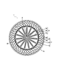
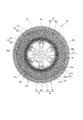
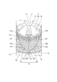
- FIG. 1 It is a side view showing typically the composition of the non-pneumatic tire concerning one embodiment of the present invention. It is explanatory drawing seen from the tire side surface which shows typically the structure of the non-pneumatic tire which concerns on other one Embodiment of this invention. It is explanatory drawing which expands and shows a part of FIG.
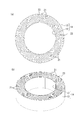
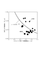
- the inner cylinder and outer cylinder connected with the connection member by another example are shown, (a) is a front view, (b) is a perspective view. It is a graph which shows the relationship between 240 degreeC melt viscosity (nu) (Pa * sec) of the resin composition used for the tire of the Example and the comparative example, and the average interface distance (tau) (micrometer) between elastomers.
- the tire of the present invention contains a polyamide resin and an elastomer having a glass transition point of 25 ° C. or less,
- the melt viscosity ⁇ (Pa ⁇ sec) at 240 ° C. and the average inter-interface distance ⁇ ( ⁇ m) between elastomers are expressed by the following formula (1): ⁇ ⁇ 34.369 ⁇ -3.525 (1)
- a resin composition satisfying the above relationship is used.
- Such a tire of the present invention has high durability.
- the dispersion of the elastomer in the resin composition as a raw material It is effective to improve the property, and at that time, it is also important to suppress an increase in the melt viscosity of the resin composition. Therefore, the present inventor diligently studied the kneading conditions in the production of the resin composition, the melt viscosity ⁇ of the resin composition at 240 ° C., the average inter-interface distance ⁇ between the elastomers, and the durability of the tire using the same.
- the melt viscosity ⁇ at 240 ° C. is an indicator of the fluidity of the resin composition at the time of molding, while the average inter-interface distance ⁇ between elastomers is an indicator of the dispersibility of the elastomer in the resin composition, If it is a resin composition which satisfy
- the melt viscosity ⁇ at 240 ° C. is low, the fluidity of the resin composition is excellent even if the average inter-interface distance ⁇ between the elastomers is long.
- the durability of the tire can be improved by compensating for the poorness of the tire. Conversely, if the average inter-interface distance ⁇ between the elastomers is short, even if the melt viscosity ⁇ at 240 ° C. is high, the dispersibility of the elastomer By being excellent, the poor fluidity of the resin composition can be compensated for and the durability of the tire can be improved.
- the melt viscosity ⁇ at 240 ° C. and the average inter-interface distance ⁇ between the elastomers are not particularly limited as long as the relationship of the above formula (1) is satisfied.
- the melt viscosity ⁇ is preferably in the range of 250 to 3000 Pa ⁇ sec, and the average inter-interface distance ⁇ between the elastomers is preferably in the range of 0.2 to 0.5 ⁇ m. If the melt viscosity ⁇ at 240 ° C.
- the fluidity of the resin composition and the dispersibility of the elastomer can be further improved.
- the resin composition used for the tire of the present invention contains a polyamide resin.
- the polyamide resin is not particularly limited, and any polyamide resin can be used, and an aliphatic diamine having 6 to 20 carbon atoms and an aliphatic dicarboxylic acid having 10 to 20 carbon atoms are polymerized.
- a polyamide resin is preferable.
- a polyamide resin obtained by polymerizing an aliphatic diamine having 6 to 20 carbon atoms and an aliphatic dicarboxylic acid having 10 to 20 carbon atoms is difficult to absorb water, so that the water absorption rate of a tire using the resin composition can be reduced.
- the aliphatic diamine having 6 to 20 carbon atoms constituting the polyamide resin for example, 1,6-hexamethylenediamine, 1,7-heptamethylenediamine, 1,8-octamethylenediamine, 1,9 -Nonamethylenediamine, 1,10-decamethylenediamine, 1,11-undecamethylenediamine, 1,12-dodecamethylenediamine, 1,13-tridecamethylenediamine, 1,14-tetradecamethylenediamine, 1, 16-hexadecamethylenediamine, 1,18-octadecamethylenediamine, 2,2,4-trimethyl-1,6-hexamethylenediamine, 2,4,4-trimethyl-1,6-hexamethylenediamine, 2- And methyl-1,8-octamethylenediamine.
- Examples of the aliphatic dicarboxylic acid having 10 to 20 carbon atoms constituting the polyamide resin include 1,10-decanedioic acid (so-called sebacic acid), 1,11-undecanedioic acid, and 1,12-dodecane.
- Examples include diacid, 1,14-tetradecanedioic acid, 1,16-hexadecanedioic acid, 1,18-octadecanedioic acid, 1,20-eicosanedioic acid, and the like.
- a polymer obtained by polymerizing the above aliphatic diamine having 6 to 20 carbon atoms and an aliphatic dicarboxylic acid having 10 to 20 carbon atoms that is, an aliphatic diamine having 6 to 20 carbon atoms and an aliphatic dicarboxylic acid having 10 to 20 carbon atoms.
- Examples of the condensation polymer with an acid include polyamide 610 (PA610), polyamide 612 (PA612), polyamide 1010 (PA1010), polyamide 1012 (PA1012), and the like.
- the polyamide resin can be synthesized by a known method by condensation polymerization of an aliphatic diamine having 6 to 20 carbon atoms and an aliphatic dicarboxylic acid having 10 to 20 carbon atoms, but a commercially available product can also be used.
- the product names “Hyprolon 70NN”, “Hyprolon 70SFN”, “Hyprolon 90NN”, “Hyprolon 200NN”, “Hyprolon 400NN”, etc., manufactured by Arkema, Inc. can be used.
- a polymer obtained by polymerizing the above aliphatic diamine having 6 to 20 carbon atoms and an aliphatic dicarboxylic acid having 10 to 20 carbon atoms that is, an aliphatic diamine having 6 to 20 carbon atoms and an aliphatic dicarboxylic acid having 10 to 20 carbon atoms.
- the condensation polymer with an acid has the following formula (2): As shown in Fig. 2, two amide bonds in the main chain are in opposite directions.
- a polyamide obtained by ring-opening polymerization of lactam has the following formula (3): As shown, the amide bonds in the main chain are in the same direction.
- Polyamides with two amide bonds in the main chain in opposite directions have lower crystallinity and higher degree of molecular chain freedom than polyamides with amide bonds in the main chain in the same direction. High mechanical strength.
- polyamides in which the amide bonds in the main chain are in two opposite directions have a small entropy difference between the melt and the crystal, and thus have a high melting point and excellent heat resistance. Therefore, by using a resin composition containing a condensation polymer of an aliphatic diamine having 6 to 20 carbon atoms and an aliphatic dicarboxylic acid having 10 to 20 carbon atoms for a tire, physical properties such as rigidity and strength of the tire are improved. Thus, the durability can be further improved.
- 60 to 90% by mass of the polyamide resin is polyamide 610 having a melt flow rate (MFR) under a load of 2.16 kg at 240 ° C. of 50 g / 10 min or less, and the polyamide resin Is preferably polyamide 610 having a melt flow rate (MFR) under a load of 2.16 kg at 240 ° C. of 60 g / 10 min or more.
- 60 to 90% by mass of the polyamide resin is polyamide 610 having a melt flow rate (MFR) of 50 g / 10 min or less at 240 ° C. under a load of 2.16 kg, and 10 to 40% by mass of the polyamide resin is 240 ° C.
- melt flow rate 60 g / 10 min or more under 2.16 kg load
- MFR melt flow rate
- the content of the polyamide resin in the resin composition is preferably in the range of 60 to 90% by mass, more preferably in the range of 65 to 85% by mass, and still more preferably in the range of 70 to 80% by mass. If the content of the polyamide resin in the resin composition is 60 to 90% by mass, the durability of the tire is further improved.
- the resin composition used for the tire of the present invention contains an elastomer having a glass transition point (Tg) of 25 ° C. or less, and the elastomer preferably has a glass transition point (Tg) of 0 ° C. or less.
- Tg is more preferably ⁇ 20 ° C. or lower.
- any elastomer can be used as the elastomer.
- the elastomer is an ethylene-propylene rubber, poly ⁇ -olefin, acrylic rubber, styrene-ethylene-butylene-styrene copolymer, and ethylene-1-butene copolymer. It is preferable to include at least one selected from the group consisting of polymers.
- the elastomer may be an unmodified elastomer or a modified elastomer. However, a modification in which maleic anhydride or an epoxy-terminated acrylic ester is copolymerized or grafted on at least a part of the elastomer. An elastomer is preferred.
- the modified elastomer in which these compounds are copolymerized or grafted reacts with the end group of the polyamide resin to improve the dispersibility in the resin composition, thereby further improving the elasticity and durability of the tire.
- the elastomer in the resin composition, it is preferable that 10 to 50% by mass of the elastomer is a modified elastomer and 90 to 50% by mass of the elastomer is an unmodified elastomer.
- 10-50% by mass of the elastomer is a modified elastomer and 90-50% by mass of the elastomer is an unmodified elastomer
- the modified elastomer wraps around the unmodified elastomer and is unevenly distributed at the polyamide / elastomer interface. Therefore, the durability of the tire is further improved.
- the elastomer preferably has a melt flow rate (MFR) under a load of 2.16 kg at 230 ° C. of 15 g / 10 min or more. If the melt flow rate (MFR) under the load of 2.16 kg at 230 ° C. of the elastomer is 15 g / 10 min or more, the melt viscosity ⁇ at 240 ° C. of the resin composition will be low, and the fluidity of the resin composition will be high. Therefore, the durability of the tire is further improved.
- MFR melt flow rate
- the content of the elastomer in the resin composition is preferably in the range of 10 to 40% by mass, and more preferably in the range of 15 to 35% by mass.
- the elastomer content in the resin composition is 10 to 40% by mass, the durability of the tire is further improved.
- the resin composition used for the tire of the present invention preferably further contains a plasticizer.
- the melt viscosity ⁇ at 240 ° C. of the resin composition becomes low and the fluidity of the resin composition becomes high, so that the durability of the tire is further improved.
- the plasticizer is not particularly limited, and any plasticizer can be used. From the viewpoint of reducing the melt viscosity ⁇ at 240 ° C. of the resin composition, N-butylbenzenesulfonamide is used. 2-ethylhexyl-4-hydroxybenzoate and N- (2-hydroxypropyl) benzenesulfonamide are preferred. These plasticizers may be used alone or in combination of two or more.
- the plasticizer content is preferably in the range of 1 to 20% by mass, more preferably in the range of 2 to 10% by mass.
- the plasticizer content is 1 to 20% by mass, the durability of the tire is further improved.
- the resin composition includes, for example, a heat-resistant agent, an ultraviolet absorber, a light stabilizer, an anti-aging agent, an antistatic agent, a lubricant, a crystal nucleating agent, and an adhesive.
- a heat-resistant agent such as a heat-resistant agent, an ultraviolet absorber, a light stabilizer, an anti-aging agent, an antistatic agent, a lubricant, a crystal nucleating agent, and an adhesive.
- One or more additives such as a property-imparting agent, an antifogging agent, a release agent, a filler, a pigment, a dye, a fragrance, and a flame retardant can be included.
- the resin composition can be produced by arbitrarily blending the polyamide resin and the elastomer with other components selected as necessary, and appropriately adjusting the kneading conditions.
- kneading conditions for controlling the melt viscosity ⁇ at 240 ° C. and the average inter-interface distance ⁇ between the elastomers to satisfy the relationship of the formula (1), the rotational speed of the screw of the kneader, the flow rate of the polyamide resin.
- Examples include kneading temperature, elastomer charging position, screw configuration, L / D of the kneader.
- TEX44 ⁇ III screw diameter: 44 mm, L / D52.5 manufactured by Nippon Steel Works was used, and the cylinder temperature was 225 to 240 ° C., the rotation speed was 300 rpm, and the discharge rate was 150 kg / h.
- the resin composition can be processed into a tire member having a desired shape, for example, a skeleton member, using various molding methods.
- a molding method injection molding is preferable.
- the tire of the present invention is preferably a tire whose skeleton member is made of a resin composition.
- the tire skeleton member is a member constituting the tire skeleton, more specifically, a member that supports the rubber member from the inside of the tire to the outside in order to maintain the shape of the tire tread.
- it is an inner cylinder, an outer cylinder, a connection member (spoke structure), etc. in a non-pneumatic tire.
- FIG. 1 is a side view schematically showing the configuration of a non-pneumatic tire according to an embodiment of the present invention.
- the scale is appropriately changed to make each member a recognizable size.
- the non-pneumatic tire 1 includes a wheel portion 2 attached to an axle and a tire portion 7 disposed on the outer periphery of the wheel portion 2.
- the non-pneumatic tire 1 is used for bicycles, two-wheeled vehicles, automobiles, and the like (hereinafter, these generic names are simply referred to as vehicles).
- the wheel portion 2 is formed in a disc shape
- the tire portion 7 is formed in an annular shape
- the central axes are located on a common axis.
- This common axis is referred to as a central axis O1
- a direction along the central axis O1 is referred to as a tire width direction.
- a direction around the central axis O1 is referred to as a tire circumferential direction
- a direction orthogonal to the central axis O1 is referred to as a tire radial direction.
- the wheel portion 2 includes a cylindrical boss 8 extending in the tire width direction around the central axis O1, a mounting cylinder portion 2a fixed to the outer peripheral surface of the boss 8, and a mounting cylinder portion 2a.
- the exterior cylinder part 2c enclosed from the tire radial direction outer side and the some rib 2b which mutually connects the mounting cylinder part 2a and the exterior cylinder part 2c are provided.
- the boss 8 is made of aluminum. Since the boss 8 is rotatably supported by the axle, the wheel portion 2 is attached to the axle.
- the boss 8 may be formed of a metal other than aluminum or a nonmetal. In the tire width direction, the width of the boss 8 is larger than the widths of the mounting tube portion 2a, the plurality of ribs 2b, and the exterior tube portion 2c.
- the mounting cylinder 2a and the exterior cylinder 2c are arranged coaxially with the boss 8, respectively.
- the plurality of ribs 2b are arranged at equal intervals in the tire circumferential direction.
- Each of the plurality of ribs 2b extends radially around the boss 8.
- the mounting cylinder part 2a, the plurality of ribs 2b, and the exterior cylinder part 2c are integrally formed of a thermoplastic resin.
- the wheel part 2 can be shape
- hub 8, the mounting cylinder part 2a, the some rib 2b, and the exterior cylinder part 2c may each be formed separately.
- the mounting cylinder portion 2a, the plurality of ribs 2b, and the exterior cylinder portion 2c may be formed of a material other than the thermoplastic resin.
- the tire part 7 is displaceable between the inner cylinder 6 fitted on the exterior cylinder part 2c of the wheel part 2, the outer cylinder 4 surrounding the inner cylinder 6 from the outer side in the tire radial direction, and the inner cylinder 6 and the outer cylinder 4. And an elastically deformable connecting member 3 to be connected.
- a tread member 5 is fitted on the outer peripheral surface of the outer cylinder 4.
- the inner cylinder 6 is attached to the axle via the wheel portion 2.
- the central axes of the inner cylinder 6 and the outer cylinder 4 are arranged coaxially with the central axis O1.
- the inner cylinder 6, the connecting member 3, and the outer cylinder 4 are arranged in a state in which the center portions in the tire width direction coincide with each other in the tire width direction.
- the inner cylinder 6, the connecting member 3, and the outer cylinder 4 are integrally formed of a thermoplastic resin.
- the tire part 7 can be shape
- the inner cylinder 6, the connection member 3, and the outer cylinder 4 may each be formed separately.
- the inner cylinder 6, the connection member 3, and the outer cylinder 4 may be formed with materials other than a thermoplastic resin.
- the tire portion 7 and the wheel portion 2 may be integrally formed or may be formed separately.
- the wheel portion 2 has a function of connecting the boss 8 and the tire portion 7, and the tire portion 7 has a function of absorbing vibration transmitted from the ground to the boss 8.
- the wheel part 2 and the tire part 7 may be formed of different materials.
- the tread member 5 is made of, for example, vulcanized rubber obtained by vulcanizing a rubber composition containing natural rubber or the like, or a thermoplastic material.
- the thermoplastic material include thermoplastic resins such as urethane resin, olefin resin, vinyl chloride resin, and polyamide resin. From the viewpoint of wear resistance, it is preferable to form the tread member 5 from vulcanized rubber.
- the connecting member 3 is formed in a rectangular plate shape that is curved as a whole, with the front and back surfaces facing the tire circumferential direction and the side surfaces facing the tire width direction.
- the connecting member 3 is made of an elastically deformable material, and connects the outer peripheral surface side of the inner cylinder 6 and the inner peripheral surface side of the outer cylinder 4 so as to be relatively elastically displaceable.
- a plurality of connecting members 3 are arranged at equal intervals in the tire circumferential direction.
- Each of the plurality of connecting members 3 has an inner part 3 a connected to the inner cylinder 6 and an outer part 3 b connected to the outer cylinder 4.
- the inner side portion 3a and the outer side portion 3b are connected to each other at the central portion of the connecting member 3 in the tire radial direction, and cross at an obtuse angle at the connecting portion in a side view.
- the thickness of the inner portion 3a in the tire circumferential direction is smaller than the thickness of the outer portion 3b in the tire circumferential direction.
- the thickness of the outer portion 3b in the tire circumferential direction is gradually increased toward the outer side in the tire radial direction.
- the skeleton member corresponds to the inner cylinder 6, the outer cylinder 4, and the connecting member 3 of the non-pneumatic tire, and the inner cylinder 6, the outer cylinder 4, and the connecting member.
- 3 contains the above-described resin composition, that is, a polyamide resin, and an elastomer having a glass transition point of 25 ° C. or less, and the melt viscosity ⁇ at 240 ° C. and the average interfacial distance ⁇ between the elastomers are expressed by the formula ( It consists of a resin composition that satisfies the relationship 1).
- FIG. 2 is an explanatory view seen from the side of the tire, schematically showing the configuration of a non-pneumatic tire according to another embodiment of the present invention.
- FIG. 3 is an enlarged view of a part of FIG. It is explanatory drawing shown.
- the non-pneumatic tire 10 of this embodiment includes a wheel portion 11 attached to an axle (not shown), an inner cylinder 12 and an inner cylinder 12 that are externally mounted on the wheel portion 11.
- a ring member 14 having an outer cylinder 13 that surrounds the outer side in the radial direction, and a plurality of connecting members 15 that are arranged between the inner cylinder 12 and the outer cylinder 13 along the tire circumferential direction and connect the cylinders 12 and 13 together.
- a tread member 16 made of vulcanized rubber that integrally covers the outer periphery of the ring member 14.
- the wheel portion 11, the inner cylinder 12, the outer cylinder 13, and the tread member 16 are arranged coaxially with the common shaft and with the central portions in the tire width direction aligned with each other.
- the axis O, the direction orthogonal to the axis O is referred to as the tire radial direction, and the direction around the axis O is referred to as the tire circumferential direction.
- the wheel portion 11 connects the mounting cylinder portion 17 to which the front end portion of the axle is mounted, the outer ring portion 18 that surrounds the mounting cylinder portion 17 from the outside in the tire radial direction, and the mounting cylinder portion 17 and the outer ring portion 18. And a plurality of ribs 19 (see FIGS. 2 and 3).
- the mounting cylinder portion 17, the outer ring portion 18, and the rib 19 are integrally formed of a metal material such as an aluminum alloy, for example.
- the mounting cylinder part 17 and the outer ring part 18 are each formed in a cylindrical shape and arranged coaxially with the axis O. Further, the plurality of ribs 19 are arranged at equal intervals in the circumferential direction.
- the connecting member 15 includes a first elastic connecting plate 21 and a second elastic connecting plate 22 that connect the inner cylinder 12 and the outer cylinder 13 of the ring member 14 to each other.
- a plurality of first elastic coupling plates 21 are arranged along the tire circumferential direction at one tire width direction position, and the second elastic coupling plates 22 are arranged in the other tire width direction different from the one tire width direction position.
- a plurality of tires are arranged at positions along the tire circumferential direction. For example, 60 first elastic connecting plates 21 and second elastic connecting plates 22 are provided.
- the plurality of first elastic connecting plates 21 are arranged along the tire circumferential direction at the same position in the tire width direction, and the second elastic connecting plates 22 are the same apart from the first elastic connecting plate 21 in the tire width direction.
- a plurality of tires are arranged at positions in the tire width direction along the tire circumferential direction.
- the plurality of connecting members 15 are individually disposed at positions that are axially symmetric with respect to the axis O between the inner cylinder 12 and the outer cylinder 13 in the ring member 14. All the connecting members 15 have the same shape and size. Further, the width of the connecting member 15 in the tire width direction is smaller than the width of the outer cylinder 13 in the tire width direction.
- the first elastic coupling plates 21 adjacent in the tire circumferential direction are not in contact with each other, and the second elastic coupling plates 22 adjacent in the tire circumferential direction are also in non-contact with each other. Further, the first elastic connecting plate 21 and the second elastic connecting plate 22 adjacent in the tire width direction are also not in contact with each other. Note that the widths in the tire width direction of the first elastic connecting plate 21 and the second elastic connecting plate 22 are equal to each other. The thicknesses of the first elastic connecting plate 21 and the second elastic connecting plate 22 in the tire side view are also equal to each other.
- one end 21a connected to the outer cylinder 13 is located on one side in the tire circumferential direction with respect to the other end 21b connected to the inner cylinder 12, and the second elastic Of the connecting plate 22, one end 22 a connected to the outer cylinder 13 is located on the other side in the tire circumferential direction with respect to the other end 22 b connected to the inner cylinder 12. Further, the one end portions 21 a and 22 a of the first elastic connecting plate 21 and the second elastic connecting plate 22 are the same in the tire circumferential direction by making the positions in the tire width direction different from each other on the inner peripheral surface of the outer cylinder 13. It is linked to the position.
- each of the first elastic connecting plate 21 and the second elastic connecting plate 22 intermediate portions 21c, 22c positioned between the one end portions 21a, 22a and the other end portions 21b, 22b are arranged in the tire circumferential direction.
- a plurality of curved portions 21d to 21f and 22d to 22f are formed along the direction in which the elastic connecting plates 21 and 22 extend when the tire 10 is viewed from the side of the tire when viewed from the tire width direction.
- the bending directions of the bending portions 21d to 21f and 22d to 22f adjacent to each other in the extending direction among the plurality of bending portions 21d to 21f and 22d to 22f are opposite to each other. It is facing.
- the plurality of curved portions 21d to 21f formed on the first elastic connecting plate 21 are a first curved portion 21d curved so as to project toward the other side in the tire circumferential direction, a first curved portion 21d, and one end portion. Between the second curved portion 21e, which is located between the first curved portion 21d and the other end portion 21b, and between the first curved portion 21d and the other end portion 21b. And a third curved portion 21f that is curved so as to project toward one side in the tire circumferential direction.
- the plurality of curved portions 22d to 22f formed on the second elastic connecting plate 22 are a first curved portion 22d curved so as to project toward one side in the tire circumferential direction, a first curved portion 22d, and one end portion. 22a, and located between the second curved portion 22e, which is curved so as to protrude toward the other side in the tire circumferential direction, and between the first curved portion 22d and the other end 22b, and A third curved portion 22f that is curved so as to project toward the other side in the tire circumferential direction.
- the first bending portions 21d and 22d have a larger radius of curvature in a tire side view than the second bending portions 21e and 22e and the third bending portions 21f and 22f.
- the first curved portions 21d and 22d are arranged at the center in the extending direction of the first elastic connecting plate 21 and the second elastic connecting plate 22.
- both elastic connecting plates 21 and 22 are equal to each other.
- the other end portions 21 b and 22 b of both elastic connecting plates 21 and 22 are in the tire radial direction on the outer peripheral surface of the inner cylinder 12 in the tire radial direction as seen from the tire side view. They are individually connected to respective positions separated from each other by the same angle (for example, 20 ° or more and 135 ° or less) on the other side and one side in the tire circumferential direction with the axis O as the center.
- first curved portions 21d and 22d, the second curved portions 21e and 22e, and the third curved portions 21f and 22f of the first elastic connecting plate 21 and the second elastic connecting plate 22 are mutually connected to the tire.
- the direction of protrusion in the circumferential direction is opposite and the size is the same.
- each connecting member 15 in a side view of the tire is the tire radial direction as shown in a pair of first elastic connecting plate 21 and second elastic connecting plate 22 drawn with emphasis by solid lines in FIG. And is symmetrical with respect to an imaginary line L passing through the one end portions 21a and 22a of both elastic connecting plates 21 and 22.
- the one end side portion extending from the central portion in the extending direction to the one end portions 21a and 22a in the tire side view is from the central portion to the other end portion. Thickness is larger than the other end side part over 21b and 22b.
- the strength of the one end side portion where the first and second elastic connecting plates 21 and 22 are likely to be subjected to a large load is increased. Can be increased. Note that the one end side portion and the other end side portion are smoothly connected without a step.
- the ring member 14 is divided into a one-side split ring member located on one side in the tire width direction and a second-side split ring member located on the other side in the tire width direction, for example, at the center in the tire width direction. It may be.
- the one-side split ring member may be integrally formed with the first elastic connecting plate 21 and the other-side split ring member may be integrally formed with the second elastic connecting plate 22, respectively.
- the elastic connecting plate 21, the other-side split ring member, and the second elastic connecting plate 22 may be integrally formed by injection molding.
- the ring member 14 is fixed to the wheel portion 11 in a state where the inner cylinder 12 is externally fitted to the wheel portion 11.
- skeleton member corresponds to the said ring member 14 and the said connection member 15 of a non-pneumatic tire
- the inner cylinder 12 and outer cylinder of this ring member 14 13 and the connecting member 15 contains the above-described resin composition, that is, a polyamide resin and an elastomer having a glass transition point of 25 ° C. or lower, and an average interface between the melt viscosity ⁇ at 240 ° C. and the elastomer
- the distance ⁇ is made of a resin composition that satisfies the relationship of the formula (1).
- the inner cylinder 12, the outer cylinder 13, and the connecting member 15 need to be made of the above-described resin composition. Different resin compositions may be used for the inner cylinder 12, the outer cylinder 13, and the connecting member 15 that are configured.
- the tread member 16 is formed in a cylindrical shape and integrally covers the outer peripheral surface side of the outer cylinder 13 of the ring member 14 over the entire area.
- the tread member 16 is formed of a vulcanized rubber obtained by vulcanizing a rubber composition containing, for example, natural rubber from the viewpoint of wear resistance and the like.
- the adhesive layer 25 is provided between the outer cylinder 13 and the tread member 16 of the ring member 14 and interposes the bonding between the outer cylinder 13 and the tread member 16.
- a commercially available adhesive can be used for the adhesive layer. Examples thereof include, but are not limited to, cyanoacrylate adhesives and epoxy adhesives.
- FIG. 4A and 4B show an inner cylinder and an outer cylinder connected by a connecting member according to another example.
- FIG. 4A is a front view
- FIG. 4B is a perspective view.
- the connecting member 23 is configured by only the first elastic connecting plate 21, unlike the connecting member 15 configured by the first elastic connecting plate 21 and the second elastic connecting plate 22.
- a plurality of first elastic connecting plates 21 constituting the connecting member 23 are arranged between the inner cylinder 12 and the outer cylinder 13 along the tire circumferential direction, and connect both the cylinders 12 and 13 together.
- Other configurations and operations are the same as those of the connecting member 15.
- Resin component of resin composition The following resins 1 and 2 were used as the resin components of the resin compositions used in the tires of Examples and Comparative Examples.
- Elastomer component of resin composition The following elastomers A to E were used as elastomer components of the resin compositions used in the tires of Examples and Comparative Examples.
- the modification rate of elastomers A to E was measured by the following method.
- Plasticizer component of resin composition As a plasticizer component of the resin composition used in the tires of Examples 5 and 6, N-butylbenzenesulfonamide (trade name “BM-4” manufactured by Daihachi Chemical Industry Co., Ltd.) was used.
- Examples 1 to 10 and Comparative Examples 1 to 7 Using TEX44 ⁇ III manufactured by Nippon Steel, according to the formulation shown in Table 1, polyamide and elastomer were dry blended in advance at a predetermined ratio and charged into the hopper.
- the plasticizer used was a liquid injection pump, and the flow rate of the polyamide resin
- a resin composition was prepared by adjusting the number of rotations of the screw.
- the inner cylinder 6, the outer cylinder 4 and the connecting member 3 of the non-pneumatic tire shown in FIG. 1 are formed by injection molding, and the inner cylinder 6, the outer cylinder 4 and the connecting member 3 are molded.
- the non-pneumatic tire used as a sample was produced.
- All of the sample non-pneumatic tires are bicycle tires having a tire size of 20 inches in outer diameter (wheel size ⁇ 340 mm, width 40 mm), and their structures are shown in FIG.
- FIG. 5 shows the relationship between the melt viscosity ⁇ (Pa ⁇ sec) at 240 ° C. of the resin compositions used in the tires of Examples and Comparative Examples and the average inter-interface distance ⁇ ( ⁇ m) between elastomers.
- the following evaluation was performed with respect to the non-pneumatic tire of each produced sample.
- ⁇ Tire durability (endurance over bumps)> For each sample, a hemispherical protrusion having a diameter of 20 mm is attached to the drum durability tester, a load of 650 N is applied in an environment of 40 ° C., and a travel distance until failure is measured when traveling at 50 km / h. Thus, tire durability was evaluated. In addition, about the result, the travel distance of each test tire was displayed by the index value when the travel distance of the tire of the comparative example 1 was set to 100. The larger the index value, the higher the durability of the tire.
Landscapes
- Chemical & Material Sciences (AREA)
- Health & Medical Sciences (AREA)
- Chemical Kinetics & Catalysis (AREA)
- Medicinal Chemistry (AREA)
- Polymers & Plastics (AREA)
- Organic Chemistry (AREA)
- Engineering & Computer Science (AREA)
- Mechanical Engineering (AREA)
- General Chemical & Material Sciences (AREA)
- Tires In General (AREA)
- Compositions Of Macromolecular Compounds (AREA)
Abstract
本発明の課題は、樹脂組成物を用いた、耐久性の高いタイヤを提供することであり、その解決手段は、ポリアミド樹脂と、ガラス転移点が25℃以下のエラストマーと、を含有し、240℃での溶融粘度ν(Pa・sec)とエラストマー間の平均界面間距離τ(μm)とが下記式(1): ν<34.369τ-3.525 ・・・ (1) の関係を満たす樹脂組成物を用いたことを特徴とするタイヤである。
Description
本発明は、タイヤに関するものである。
ポリアミド樹脂は、加工性、耐薬品性、耐熱性等に優れる樹脂として知られており、これらの特性を利用して、射出成形品、押出成形品、フィムル等の種々の樹脂製品に使用されている。
例えば、下記特許文献1には、ポリアミド樹脂と、該ポリアミド樹脂と反応性の官能基を有する変性用ポリマーと、を含むポリアミド樹脂組成物が開示されており、該ポリアミド樹脂組成物を空気入りタイヤのインナーライナーやホース等の樹脂製品に使用することが開示されている。
また、近年、パンクの発生を回避するため、内部に加圧空気を充填する必要の無いタイヤとして、骨格部材を樹脂組成物から形成した非空気入りタイヤも提案されている。
例えば、下記特許文献1には、ポリアミド樹脂と、該ポリアミド樹脂と反応性の官能基を有する変性用ポリマーと、を含むポリアミド樹脂組成物が開示されており、該ポリアミド樹脂組成物を空気入りタイヤのインナーライナーやホース等の樹脂製品に使用することが開示されている。
また、近年、パンクの発生を回避するため、内部に加圧空気を充填する必要の無いタイヤとして、骨格部材を樹脂組成物から形成した非空気入りタイヤも提案されている。
しかしながら、上述のような非空気入りタイヤを車両に取り付けて使用すると、石跳ね、縁石擦れ等によって、樹脂組成物からなる骨格部材に亀裂が入ることが考えられる。こうした亀裂は、小さな亀裂であっても、タイヤ走行中に進展して、骨格部材の耐久性が低下することが考えられる。こうした亀裂の進展を抑制する手法として、樹脂にエラストマーを練り込み、エラストマーによって、亀裂の進展を抑制する方法が挙げられる。ここで、亀裂進展の抑制効果は、エラストマーの分散性が良い程良好であるが、樹脂とエラストマーの混練条件の強化や、エラストマーの変性率の向上等の一般的な手法でエラストマーの分散性を改良すると、樹脂及びエラストマーを含む樹脂組成物の溶融粘度が著しく上昇する。そして、樹脂組成物の溶融粘度が上昇することで、例えば、射出成型による生産性が悪くなるばかりか、金型を流動する樹脂組成物の合流部(ウェルド)で十分に樹脂組成物が混ざらず、得られた骨格部材の強度が低下し、耐久性の低下につながる。
そこで、本発明は、上記従来技術の問題を解決し、樹脂組成物を用いた、耐久性の高いタイヤを提供することを課題とする。
上記課題を解決する本発明の要旨構成は、以下の通りである。
本発明のタイヤは、ポリアミド樹脂と、ガラス転移点が25℃以下のエラストマーと、を含有し、
240℃での溶融粘度ν(Pa・sec)とエラストマー間の平均界面間距離τ(μm)とが下記式(1):
ν<34.369τ-3.525 ・・・ (1)
の関係を満たす樹脂組成物を用いたことを特徴とする。
かかる本発明のタイヤは、高い耐久性を有する。
240℃での溶融粘度ν(Pa・sec)とエラストマー間の平均界面間距離τ(μm)とが下記式(1):
ν<34.369τ-3.525 ・・・ (1)
の関係を満たす樹脂組成物を用いたことを特徴とする。
かかる本発明のタイヤは、高い耐久性を有する。
ここで、本発明において、樹脂組成物の240℃での溶融粘度νは、島津製作所製のキャピラリーレオメーターCFT-100Dを使用し、2.16kg荷重下での測定結果から付属ソフトウェアにて算出した。
また、本発明において、樹脂組成物における、エラストマー間の平均界面間距離τは、下記の方法で算出した。
まず、30μm×30μmの領域をAFMにて、3箇所確認し、ImageJにて測定した画像を処理してエラストマーの平均粒子径を求めた。この際、0.09μm2以下のものはノイズとして除去した。その後、30μm×30μmの領域内に前記方法にて算出した平均粒子径のエラストマーを等間隔に配置した時の界面間距離を求め、これをエラストマー間の平均界面間距離τとした。
まず、30μm×30μmの領域をAFMにて、3箇所確認し、ImageJにて測定した画像を処理してエラストマーの平均粒子径を求めた。この際、0.09μm2以下のものはノイズとして除去した。その後、30μm×30μmの領域内に前記方法にて算出した平均粒子径のエラストマーを等間隔に配置した時の界面間距離を求め、これをエラストマー間の平均界面間距離τとした。
本発明のタイヤの好適例においては、前記ポリアミド樹脂が、炭素数6~20の脂肪族ジアミン及び炭素数10~20の脂肪族ジカルボン酸を重合させてなるポリアミド樹脂である。この場合、タイヤを高湿度環境下で使用しても、タイヤが高い耐久性を維持できる。
本発明のタイヤの他の好適例においては、前記エラストマーが、ポリエチレン、ポリプロピレン、エチレン-プロピレンゴム、エチレン-1-ブテン共重合体、ポリα-オレフィン、アクリルゴム及びスチレン-エチレン-ブチレン-スチレン共重合体からなる群より選択される少なくとも一種を含む。この場合、タイヤの耐久性を更に向上させることができる。
本発明のタイヤの他の好適例においては、前記エラストマーの少なくとも一部に、無水マレイン酸が、共重合又はグラフトされている。この場合、タイヤの耐久性を更に向上させることができる。
本発明のタイヤの他の好適例においては、前記エラストマーの少なくとも一部に、エポキシ末端アクリル酸エステルが、共重合又はグラフトされている。この場合も、タイヤの耐久性を更に向上させることができる。
本発明のタイヤに用いる樹脂組成物は、前記ポリアミド樹脂を60~90質量%含むことが好ましく、65~85質量%含むことが更に好ましく、70~80質量%含むことがより一層好ましい。この場合、タイヤの耐久性を更に向上させることができる。
本発明のタイヤの他の好適例においては、前記エラストマーの10~50質量%が変性エラストマーであり、前記エラストマーの90~50質量%が未変性エラストマーである。この場合、タイヤの耐久性を更に向上させることができる。
本発明のタイヤに用いる樹脂組成物は、更に、可塑剤を1~20質量%含有することが好ましい。この場合、樹脂組成物の240℃での溶融粘度νが低くなり、それを用いたタイヤの耐久性を更に向上させることができる。
ここで、前記可塑剤が、N-ブチルベンゼンスルホンアミド、2-エチルヘキシル-4-ヒドロキシベンゾエート、及びN-(2-ヒドロキシプロピル)ベンゼンスルホンアミドからなる群から選択される少なくとも一種を含むことが好ましい。この場合、タイヤの耐久性を更に向上させることができる。
本発明のタイヤに用いる樹脂組成物において、前記エラストマーは、230℃における2.16kg荷重下でのメルトフローレート(MFR)が15g/10min以上であることが好ましい。この場合、樹脂組成物中のエラストマー間の平均界面間距離τが短くなり、それを用いたタイヤの耐久性を更に向上させることができる。
本発明のタイヤの他の好適例においては、前記ポリアミド樹脂の60~90質量%が、240℃における2.16kg荷重下でのメルトフローレート(MFR)が50g/10min以下のポリアミド610であり、前記ポリアミド樹脂の10~40質量%が、240℃における2.16kg荷重下でのメルトフローレート(MFR)が60g/10min以上のポリアミド610である。この場合、タイヤの耐久性を更に向上させることができる。
なお、本発明において、エラストマー及びポリアミド樹脂のメルトフローレート(MFR)は、JIS K 7210に従って測定した値である。
本発明の一実施態様においては、前記タイヤは、車軸に取り付けられるホイール部と、該ホイール部に外装される内筒と、該内筒をタイヤ径方向の外側から囲繞する外筒と、前記内筒と前記外筒の間にタイヤ周方向に沿って複数配置された、前記両筒同士を連結する連結部材と、前記外筒のタイヤ径方向外側に設けられたトレッド部材と、を具える非空気入りタイヤであって、前記内筒、前記外筒及び前記連結部材が、前記樹脂組成物からなる。この場合、耐久性に優れる非空気入りタイヤを得ることができる。
本発明によれば、樹脂組成物を用いた、耐久性の高いタイヤを提供することができる。
以下に、本発明のタイヤを、その実施形態に基づき、詳細に例示説明する。
本発明のタイヤは、ポリアミド樹脂と、ガラス転移点が25℃以下のエラストマーと、を含有し、
240℃での溶融粘度ν(Pa・sec)とエラストマー間の平均界面間距離τ(μm)とが下記式(1):
ν<34.369τ-3.525 ・・・ (1)
の関係を満たす樹脂組成物を用いたことを特徴とする。かかる本発明のタイヤは、高い耐久性を有する。
240℃での溶融粘度ν(Pa・sec)とエラストマー間の平均界面間距離τ(μm)とが下記式(1):
ν<34.369τ-3.525 ・・・ (1)
の関係を満たす樹脂組成物を用いたことを特徴とする。かかる本発明のタイヤは、高い耐久性を有する。
上述のように、樹脂とエラストマーを含む樹脂組成物を用いて製造したタイヤの亀裂の進展を抑制して、タイヤの耐久性を向上させるには、原材料となる樹脂組成物中の、エラストマーの分散性を向上させることが有効であり、また、その際、樹脂組成物の溶融粘度の上昇を抑制することも重要である。そこで、本発明者は、樹脂組成物の製造における混練条件を鋭意検討し、樹脂組成物の240℃での溶融粘度ν及びエラストマー間の平均界面間距離τと、それを用いたタイヤの耐久性との関係を考察したところ、上記式(1)の関係を満たす場合、かかる樹脂組成物を用いたタイヤの耐久性が大幅に向上することを見出した。
ここで、240℃での溶融粘度νは、成形時における樹脂組成物の流動性の指標となり、一方、エラストマー間の平均界面間距離τは、樹脂組成物中のエラストマーの分散性の指標となり、式(1)を満たす樹脂組成物であれば、それを用いたタイヤの耐久性を向上させることができる。
なお、式(1)の関係においては、240℃での溶融粘度νが低ければ、エラストマー間の平均界面間距離τが長くても、樹脂組成物の流動性が優れることにより、エラストマーの分散性の悪さを補って、タイヤの耐久性を向上させることができ、また、逆に、エラストマー間の平均界面間距離τが短ければ、240℃での溶融粘度νが高くても、エラストマーの分散性が優れることにより、樹脂組成物の流動性の悪さを補って、タイヤの耐久性を向上させることができる。
ここで、240℃での溶融粘度νは、成形時における樹脂組成物の流動性の指標となり、一方、エラストマー間の平均界面間距離τは、樹脂組成物中のエラストマーの分散性の指標となり、式(1)を満たす樹脂組成物であれば、それを用いたタイヤの耐久性を向上させることができる。
なお、式(1)の関係においては、240℃での溶融粘度νが低ければ、エラストマー間の平均界面間距離τが長くても、樹脂組成物の流動性が優れることにより、エラストマーの分散性の悪さを補って、タイヤの耐久性を向上させることができ、また、逆に、エラストマー間の平均界面間距離τが短ければ、240℃での溶融粘度νが高くても、エラストマーの分散性が優れることにより、樹脂組成物の流動性の悪さを補って、タイヤの耐久性を向上させることができる。
本発明のタイヤに用いる樹脂組成物において、240℃での溶融粘度ν及びエラストマー間の平均界面間距離τは、上記式(1)の関係を満たす限り特に限定されるものではないが、240℃での溶融粘度νは250~3000Pa・secの範囲が好ましく、また、エラストマー間の平均界面間距離τは0.2~0.5μmの範囲が好ましい。240℃での溶融粘度νが250~3000Pa・secの範囲で、エラストマー間の平均界面間距離τが0.2~0.5μmの範囲であれば、樹脂組成物の流動性とエラストマーの分散性とのバランスが良く、タイヤの耐久性を更に向上させることができる。
本発明のタイヤに用いる樹脂組成物は、ポリアミド樹脂を含有する。ここで、該ポリアミド樹脂としては、特に限定されず、任意のポリアミド樹脂を使用することができるが、炭素数6~20の脂肪族ジアミン及び炭素数10~20の脂肪族ジカルボン酸を重合させてなるポリアミド樹脂が好ましい。炭素数6~20の脂肪族ジアミン及び炭素数10~20の脂肪族ジカルボン酸を重合させてなるポリアミド樹脂は、吸水し難いため、樹脂組成物を用いたタイヤの吸水率を低減でき、その結果として、夏季等の高湿度環境下で使用したり、降雨下での使用で水と接触しても、タイヤの剛性や強度といった物性の低下を抑制でき、幅広い湿潤環境下で良好な耐久性を確保することが可能となる。
ここで、前記ポリアミド樹脂を構成する炭素数6~20の脂肪族ジアミンとしては、例えば、1,6-ヘキサメチレンジアミン、1,7-ヘプタメチレンジアミン、1,8-オクタメチレンジアミン、1,9-ノナメチレンジアミン、1,10-デカメチレンジアミン、1,11-ウンデカメチレンジアミン、1,12-ドデカメチレンジアミン、1,13-トリデカメチレンジアミン、1,14-テトラデカメチレンジアミン、1,16-ヘキサデカメチレンジアミン、1,18-オクタデカメチレンジアミン、2,2,4-トリメチル-1,6-ヘキサメチレンジアミン、2,4,4-トリメチル-1,6-ヘキサメチレンジアミン、2-メチル-1,8-オクタメチレンジアミン等が挙げられる。
また、前記ポリアミド樹脂を構成する炭素数10~20の脂肪族ジカルボン酸としては、例えば、1,10-デカン二酸(所謂、セバシン酸)、1,11-ウンデカン二酸、1,12-ドデカン二酸、1,14-テトラデカン二酸、1,16-ヘキサデカン二酸、1,18-オクタデカン二酸、1,20-エイコサン二酸等が挙げられる。
上述した炭素数6~20の脂肪族ジアミン及び炭素数10~20の脂肪族ジカルボン酸を重合させてなるもの、即ち、炭素数6~20の脂肪族ジアミンと炭素数10~20の脂肪族ジカルボン酸との縮合重合体としては、例えば、ポリアミド610(PA610)、ポリアミド612(PA612)、ポリアミド1010(PA1010)、ポリアミド1012(PA1012)等が挙げられる。前記ポリアミド樹脂は、公知の方法で、炭素数6~20の脂肪族ジアミンと炭素数10~20の脂肪族ジカルボン酸を縮合重合させることで合成できるが、市販品を利用することもでき、例えば、アルケマ社製の商品名「Hyprolon 70NN」、「Hyprolon 70SFN」、「Hyprolon 90NN」、「Hyprolon 200NN」、「Hyprolon 400NN」等を利用できる。
上述した炭素数6~20の脂肪族ジアミン及び炭素数10~20の脂肪族ジカルボン酸を重合させてなるもの、即ち、炭素数6~20の脂肪族ジアミンと炭素数10~20の脂肪族ジカルボン酸との縮合重合体は、下記式(2):

に示すように、主鎖中のアミド結合が2つずつ逆方向になっている。
一方、例えば、ラクタムの開環重合で得られるポリアミドは、下記式(3):

に示すように、主鎖中のアミド結合が同一方向になっている。
主鎖中のアミド結合が2つずつ逆方向になっているポリアミドは、主鎖中のアミド結合が同一方向になっているポリアミドに比べて、結晶性が低く、分子鎖の自由度が高いため、機械的強度が高い。また、主鎖中のアミド結合が2つずつ逆方向になっているポリアミドは、融体と結晶とのエントロピー差が小さいため、融点が高く、耐熱性にも優れている。そのため、炭素数6~20の脂肪族ジアミンと炭素数10~20の脂肪族ジカルボン酸との縮合重合体を含む樹脂組成物をタイヤに使用することで、タイヤの剛性や強度といった物性を向上させて、耐久性を更に向上させることが可能となる。
一方、例えば、ラクタムの開環重合で得られるポリアミドは、下記式(3):
主鎖中のアミド結合が2つずつ逆方向になっているポリアミドは、主鎖中のアミド結合が同一方向になっているポリアミドに比べて、結晶性が低く、分子鎖の自由度が高いため、機械的強度が高い。また、主鎖中のアミド結合が2つずつ逆方向になっているポリアミドは、融体と結晶とのエントロピー差が小さいため、融点が高く、耐熱性にも優れている。そのため、炭素数6~20の脂肪族ジアミンと炭素数10~20の脂肪族ジカルボン酸との縮合重合体を含む樹脂組成物をタイヤに使用することで、タイヤの剛性や強度といった物性を向上させて、耐久性を更に向上させることが可能となる。
前記樹脂組成物においては、前記ポリアミド樹脂の60~90質量%が、240℃における2.16kg荷重下でのメルトフローレート(MFR)が50g/10min以下のポリアミド610であり、また、前記ポリアミド樹脂の10~40質量%が、240℃における2.16kg荷重下でのメルトフローレート(MFR)が60g/10min以上のポリアミド610であることが好ましい。
ポリアミド樹脂の60~90質量%が、240℃における2.16kg荷重下でのメルトフローレート(MFR)が50g/10min以下のポリアミド610であり、前記ポリアミド樹脂の10~40質量%が、240℃における2.16kg荷重下でのメルトフローレート(MFR)が60g/10min以上のポリアミド610であれば、強度や耐疲労性を損なう事無くウェルド界面での分子の拡散が促進され、ウェルド強度を向上する事が出来るため、タイヤの耐久性が更に向上する。
ポリアミド樹脂の60~90質量%が、240℃における2.16kg荷重下でのメルトフローレート(MFR)が50g/10min以下のポリアミド610であり、前記ポリアミド樹脂の10~40質量%が、240℃における2.16kg荷重下でのメルトフローレート(MFR)が60g/10min以上のポリアミド610であれば、強度や耐疲労性を損なう事無くウェルド界面での分子の拡散が促進され、ウェルド強度を向上する事が出来るため、タイヤの耐久性が更に向上する。
前記樹脂組成物中の前記ポリアミド樹脂の含有量は、60~90質量%の範囲が好ましく、65~85質量%の範囲が更に好ましく、70~80質量%の範囲がより一層好ましい。樹脂組成物中の前記ポリアミド樹脂の含有量が60~90質量%であれば、タイヤの耐久性が更に向上する。
本発明のタイヤに用いる樹脂組成物は、ガラス転移点(Tg)が25℃以下のエラストマーを含有し、該エラストマーは、ガラス転移点(Tg)が0℃以下であることが好ましく、ガラス転移点(Tg)が-20℃以下であることが更に好ましい。樹脂組成物にガラス転移点が25℃以下のエラストマーを含ませることで、樹脂組成物が良好な弾性を維持でき、タイヤの耐久性を向上させることができる。また、エラストマーのガラス転移点(Tg)が0℃以下であれば、タイヤの低温下での耐久性が更に向上する。
前記エラストマーとしては、任意のエラストマーを使用することができるが、優れた弾性及び耐久性を得る観点からは、例えば、ポリエチレン、ポリプロピレン、エチレン-プロピレンゴム、エチレン-1-ブテン共重合体、ポリα-オレフィン、アクリルゴム、スチレン-エチレン-ブチレン-スチレン共重合体、並びにこれらの変性重合体等が挙げられる。これらの中でも、より優れた弾性及び耐久性を得る観点から、前記エラストマーが、エチレン-プロピレンゴム、ポリα-オレフィン、アクリルゴム、スチレン-エチレン-ブチレン-スチレン共重合体及びエチレン-1-ブテン共重合体からなる群から選択される少なくとも一種を含むことが好ましい。
前記エラストマーは、未変性のエラストマーであっても、変性されたエラストマーであってもよいが、エラストマーの少なくとも一部に、無水マレイン酸又はエポキシ末端アクリル酸エステルが、共重合又はグラフトされている変性エラストマーであることが好ましい。これらの化合物が共重合又はグラフトされている変性エラストマーは、ポリアミド樹脂の末端基と反応し、樹脂組成物中での分散性が向上するため、タイヤの弾性及び耐久性が更に向上する。
前記樹脂組成物においては、前記エラストマーの10~50質量%が変性エラストマーであり、前記エラストマーの90~50質量%が未変性エラストマーであることが好ましい。エラストマーの10~50質量%が変性エラストマーであり、前記エラストマーの90~50質量%が未変性エラストマーである場合、変性エラストマーが未変性エラストマーを包み込みポリアミド/エラストマー界面に偏在する事により分散と流動性を両立するため、タイヤの耐久性が更に向上する。
前記樹脂組成物において、前記エラストマーは、230℃における2.16kg荷重下でのメルトフローレート(MFR)が15g/10min以上であることが好ましい。エラストマーの230℃における2.16kg荷重下でのメルトフローレート(MFR)が15g/10min以上であれば、樹脂組成物の240℃での溶融粘度νが低くなり、樹脂組成物の流動性が高くなるため、タイヤの耐久性が更に向上する。
前記樹脂組成物中の前記エラストマーの含有量は、10~40質量%の範囲が好ましく、15~35質量%の範囲が更に好ましい。樹脂組成物中のエラストマーの含有量が10~40質量%であれば、タイヤの耐久性が更に向上する。
本発明のタイヤに用いる樹脂組成物は、更に、可塑剤を含有することが好ましい。樹脂組成物が可塑剤を含む場合、樹脂組成物の240℃での溶融粘度νが低くなり、樹脂組成物の流動性が高くなるため、タイヤの耐久性が更に向上する。
ここで、前記可塑剤としては、特に限定されず、任意の可塑剤を使用することができるが、樹脂組成物の240℃での溶融粘度νを低くする観点からは、N-ブチルベンゼンスルホンアミド、2-エチルヘキシル-4-ヒドロキシベンゾエート、及びN-(2-ヒドロキシプロピル)ベンゼンスルホンアミドが好ましい。これら可塑剤は、1種単独で使用してもよいし、2種以上を組み合わせて使用してもよい。
前記樹脂組成物において、前記可塑剤の含有量は、1~20質量%の範囲が好ましく、2~10質量%の範囲が更に好ましい。可塑剤の含有量が1~20質量%の場合、タイヤの耐久性が更に向上する。
前記樹脂組成物は、上述した、ポリアミド樹脂、エラストマー、及び可塑剤の他にも、例えば、耐熱剤、紫外線吸収剤、光安定剤、老化防止剤、帯電防止剤、滑剤、結晶核剤、粘着性付与剤、防曇剤、離型剤、充填剤、顔料、染料、香料、難燃剤等の添加剤を、一種以上含むことができる。
前記樹脂組成物は、ポリアミド樹脂及びエラストマーに、必要に応じて選択した他の成分を任意に配合して、混練条件を適宜調整することで製造することができる。
ここで、240℃での溶融粘度ν及びエラストマー間の平均界面間距離τが式(1)の関係を満たすように制御する混練条件としては、混練機のスクリューの回転数、ポリアミド樹脂の流量、混練温度、エラストマー投入位置、スクリュー構成、混練機のL/D等が挙げられる。一例では、日本製鋼所製のTEX44αIII(スクリュー径44mm、L/D52.5)を使用し、シリンダー温度225~240℃、回転数300rpm、吐出量150kg/hで実施した。
ここで、240℃での溶融粘度ν及びエラストマー間の平均界面間距離τが式(1)の関係を満たすように制御する混練条件としては、混練機のスクリューの回転数、ポリアミド樹脂の流量、混練温度、エラストマー投入位置、スクリュー構成、混練機のL/D等が挙げられる。一例では、日本製鋼所製のTEX44αIII(スクリュー径44mm、L/D52.5)を使用し、シリンダー温度225~240℃、回転数300rpm、吐出量150kg/hで実施した。
前記樹脂組成物は、種々の成形法を利用して、所望の形状のタイヤ部材、例えば、骨格部材に加工できる。ここで、成形法としては、射出成型が好ましい。
本発明のタイヤは、好ましくは、骨格部材が樹脂組成物からなるタイヤである。ここで、前記タイヤの骨格部材とは、タイヤ骨格を構成する部材、より具体的には、タイヤトレッドの形状を維持するため、タイヤ内方から外方へ向かってゴム部材を支持する部材のことを意味している。例えば、非空気入りタイヤにおける、内筒、外筒、連結部材(スポーク構造)等のことである。
次に、本発明の一実施形態に係る、非空気入りタイヤについて説明する。
図1は、本発明の一実施形態に係る非空気入りタイヤの構成を模式的に示した、側面図である。なお、以下の説明に用いる各図面では、各部材を認識可能な大きさとするため、縮尺を適宜変更している。
図1に示すように、非空気入りタイヤ1は、車軸に取り付けられるホイール部2と、ホイール部2の外周に配置されたタイヤ部7と、を具えている。
この非空気入りタイヤ1は、自転車、二輪車、自動車等(以下、これらの総称を単に車両という)に用いられる。
図1は、本発明の一実施形態に係る非空気入りタイヤの構成を模式的に示した、側面図である。なお、以下の説明に用いる各図面では、各部材を認識可能な大きさとするため、縮尺を適宜変更している。
図1に示すように、非空気入りタイヤ1は、車軸に取り付けられるホイール部2と、ホイール部2の外周に配置されたタイヤ部7と、を具えている。
この非空気入りタイヤ1は、自転車、二輪車、自動車等(以下、これらの総称を単に車両という)に用いられる。
ここで、ホイール部2は、円板状に形成され、タイヤ部7は、環状に形成されており、各中心軸は、共通軸上に位置している。この共通軸を中心軸O1といい、中心軸O1に沿う方向をタイヤ幅方向という。また、タイヤ幅方向から見た側面視において、中心軸O1を中心として周回する方向をタイヤ周方向といい、この中心軸O1に直交する方向をタイヤ径方向という。
図1に示すように、ホイール部2は、中心軸O1を中心としてタイヤ幅方向に延びる筒状のボス8と、ボス8の外周面に固定された装着筒部2aと、装着筒部2aをタイヤ径方向外側から囲う外装筒部2cと、装着筒部2a及び外装筒部2cを互いに連結する複数のリブ2bと、を具えている。
本実施形態では、ボス8は、アルミニウムにより形成されている。ボス8が車軸によって回転自在に支持されることで、ホイール部2は、車軸に取り付けられる。なお、ボス8は、アルミニウム以外の金属、又は非金属により形成されていてもよい。タイヤ幅方向において、ボス8の幅は、装着筒部2a、複数のリブ2b、及び外装筒部2cの幅よりも大きい。
装着筒部2a及び外装筒部2cは、それぞれ、ボス8と同軸に配置されている。複数のリブ2bは、例えば、タイヤ周方向に等間隔をあけて配置されている。複数のリブ2bは、それぞれ、ボス8を中心として放射状に延びている。
本実施形態では、装着筒部2a、複数のリブ2b、及び外装筒部2cは、熱可塑性樹脂により一体に形成されている。これにより、ホイール部2は、射出成形により成形することが可能であり、量産に適している。
なお、ボス8、装着筒部2a、複数のリブ2b、及び外装筒部2cは、それぞれ別体に形成されていてもよい。また、装着筒部2a、複数のリブ2b、及び外装筒部2cは、熱可塑性樹脂以外の材質により形成されていてもよい。
本実施形態では、装着筒部2a、複数のリブ2b、及び外装筒部2cは、熱可塑性樹脂により一体に形成されている。これにより、ホイール部2は、射出成形により成形することが可能であり、量産に適している。
なお、ボス8、装着筒部2a、複数のリブ2b、及び外装筒部2cは、それぞれ別体に形成されていてもよい。また、装着筒部2a、複数のリブ2b、及び外装筒部2cは、熱可塑性樹脂以外の材質により形成されていてもよい。
タイヤ部7は、ホイール部2の外装筒部2cに外嵌された内筒6と、内筒6をタイヤ径方向外側から囲う外筒4と、内筒6と外筒4とを変位自在に連結する弾性変形可能な連結部材3と、を具えている。外筒4の外周面には、トレッド部材5が嵌合されている。
内筒6は、ホイール部2を介して、車軸に取り付けられる。内筒6及び外筒4の中心軸は、中心軸O1と同軸に配置されている。内筒6、連結部材3、及び外筒4は、タイヤ幅方向において、それぞれのタイヤ幅方向の中央部が互いに一致した状態で配置されている。
本実施形態では、内筒6、連結部材3、及び外筒4は、熱可塑性樹脂により一体に形成されている。これにより、タイヤ部7は、射出成形により成形することが可能であり、量産に適している。
なお、内筒6、連結部材3、及び外筒4は、それぞれ別体に形成されていてもよい。また、内筒6、連結部材3、及び外筒4は、熱可塑性樹脂以外の材質により形成されていてもよい。
なお、内筒6、連結部材3、及び外筒4は、それぞれ別体に形成されていてもよい。また、内筒6、連結部材3、及び外筒4は、熱可塑性樹脂以外の材質により形成されていてもよい。
前記タイヤ部7及びホイール部2は、一体に形成されていてもよく、それぞれ別体に形成されていてもよい。なお、ホイール部2は、ボス8とタイヤ部7とを連結する機能を有しており、タイヤ部7は、地面からボス8に伝わる振動を吸収する機能を有している。このように、ホイール部2とタイヤ部7とは、異なる機能を有しているため、異なる材質により形成されていてもよい。
トレッド部材5は、例えば、天然ゴム等を含むゴム組成物が加硫された加硫ゴム、又は熱可塑性材料等で形成されている。熱可塑性材料としては、例えば、ウレタン樹脂、オレフィン樹脂、塩化ビニル樹脂、ポリアミド樹脂等の熱可塑性樹脂が挙げられる。なお、耐摩耗性の観点では、トレッド部材5を加硫ゴムで形成するのが好ましい。
連結部材3は、全体として湾曲した長方形状の板状に形成されており、表裏面がタイヤ周方向を向き、側面がタイヤ幅方向を向いている。連結部材3は、弾性変形可能な材質により形成され、内筒6の外周面側と外筒4の内周面側とを相対的に弾性変位自在に連結している。連結部材3は、タイヤ周方向に等間隔をあけて複数配置されている。
複数の連結部材3は、それぞれ、内筒6に接続される内側部3aと、外筒4に接続される外側部3bと、を有する。内側部3aと外側部3bとは、連結部材3のタイヤ径方向の中央部において互いに接続されており、側面視において、この接続部で鈍角に交わっている。内側部3aのタイヤ周方向における厚みは、外側部3bのタイヤ周方向における厚みよりも小さい。外側部3bのタイヤ周方向における厚みは、タイヤ径方向外側に向かうに従い、漸次大きくなっている。
そして、本実施形態に係る非空気入りタイヤでは、前記骨格部材が、非空気入りタイヤの前記内筒6、外筒4及び連結部材3に該当し、該内筒6、外筒4及び連結部材3が、上述した樹脂組成物、即ち、ポリアミド樹脂と、ガラス転移点が25℃以下のエラストマーと、を含有し、240℃での溶融粘度νとエラストマー間の平均界面間距離τとが式(1)の関係を満たす樹脂組成物からなっている。
前記内筒6、外筒4及び連結部材3を、上述した樹脂組成物から形成することで、耐久性に優れた非空気入りタイヤを提供できる。
前記内筒6、外筒4及び連結部材3を、上述した樹脂組成物から形成することで、耐久性に優れた非空気入りタイヤを提供できる。
次に、本発明の他の一実施形態に係る、非空気入りタイヤについて説明する。
図2は、本発明の他の一実施形態に係る非空気入りタイヤの構成を模式的に示す、タイヤ側面から見た説明図であり、また、図3は、図2の一部を拡大して示す説明図である。なお、図3では、理解し易いように、後述する複数の第1弾性連結板21及び複数の第2弾性連結板22のうち、それぞれ一つの第1弾性連結板21及び第2弾性連結板22のみを、実線で強調して描いている。
図2は、本発明の他の一実施形態に係る非空気入りタイヤの構成を模式的に示す、タイヤ側面から見た説明図であり、また、図3は、図2の一部を拡大して示す説明図である。なお、図3では、理解し易いように、後述する複数の第1弾性連結板21及び複数の第2弾性連結板22のうち、それぞれ一つの第1弾性連結板21及び第2弾性連結板22のみを、実線で強調して描いている。
図2及び図3に示すように、本実施形態の非空気入りタイヤ10は、車軸(図示しない)に取り付けられるホイール部11と、ホイール部11に外装される内筒12及び内筒12をタイヤ径方向の外側から囲繞する外筒13を有するリング部材14と、内筒12と外筒13の間にタイヤ周方向に沿って複数配置された、両筒12,13同士を連結する連結部材15と、リング部材14の外周を一体的に覆う加硫ゴムからなるトレッド部材16とを具える。
ここで、ホイール部11、内筒12、外筒13、及びトレッド部材16は、それぞれ共通軸と同軸に、また、タイヤ幅方向の中央部を互いに一致させて配置されており、この共通軸を軸線O、軸線Oに直交する方向をタイヤ径方向、軸線O回りに周回する方向をタイヤ周方向という。
ここで、ホイール部11、内筒12、外筒13、及びトレッド部材16は、それぞれ共通軸と同軸に、また、タイヤ幅方向の中央部を互いに一致させて配置されており、この共通軸を軸線O、軸線Oに直交する方向をタイヤ径方向、軸線O回りに周回する方向をタイヤ周方向という。
ホイール部11は、車軸の先端部が装着される装着筒部17と、装着筒部17をタイヤ径方向の外側から囲繞する外リング部18と、装着筒部17と外リング部18とを連結する複数のリブ19と、を具えている(図2,3参照)。
装着筒部17、外リング部18、及びリブ19は、例えば、アルミニウム合金等の金属材料で一体的に形成されている。装着筒部17及び外リング部18は、それぞれ、円筒状に形成され軸線Oと同軸に配設されている。また、複数のリブ19は、周方向に同等の間隔をあけて配置されている。
装着筒部17、外リング部18、及びリブ19は、例えば、アルミニウム合金等の金属材料で一体的に形成されている。装着筒部17及び外リング部18は、それぞれ、円筒状に形成され軸線Oと同軸に配設されている。また、複数のリブ19は、周方向に同等の間隔をあけて配置されている。
連結部材15は、リング部材14における内筒12と外筒13とを互いに連結する第1弾性連結板21及び第2弾性連結板22を具えている。第1弾性連結板21は、一方のタイヤ幅方向の位置にタイヤ周方向に沿って複数配置され、第2弾性連結板22は、一方のタイヤ幅方向の位置とは異なる他方のタイヤ幅方向の位置にタイヤ周方向に沿って複数配置されている。第1弾性連結板21と第2弾性連結板22は、合わせて、例えば60個設けられている。
即ち、第1弾性連結板21は、タイヤ幅方向における同一の位置にタイヤ周方向に沿って複数配置され、第2弾性連結板22は、第1弾性連結板21からタイヤ幅方向に離れた同一のタイヤ幅方向の位置にタイヤ周方向に沿って複数配置されている。
なお、複数の連結部材15は、リング部材14における内筒12と外筒13との間において、軸線Oを基準に軸対称となる位置に各別に配置されている。また、全ての連結部材15は、互いに同形同大となっている。さらに、連結部材15のタイヤ幅方向幅は、外筒13のタイヤ幅方向幅より小さくなっている。
なお、複数の連結部材15は、リング部材14における内筒12と外筒13との間において、軸線Oを基準に軸対称となる位置に各別に配置されている。また、全ての連結部材15は、互いに同形同大となっている。さらに、連結部材15のタイヤ幅方向幅は、外筒13のタイヤ幅方向幅より小さくなっている。
そして、タイヤ周方向で隣り合う第1弾性連結板21同士は、互いに非接触とされ、タイヤ周方向で隣り合う第2弾性連結板22同士も、互いに非接触となっている。さらに、タイヤ幅方向で隣り合う第1弾性連結板21及び第2弾性連結板22同士も、互いに非接触となっている。
なお、第1弾性連結板21及び第2弾性連結板22のそれぞれのタイヤ幅方向幅は、互いに同等になっている。また、第1弾性連結板21及び第2弾性連結板22のそれぞれのタイヤ側面視における厚さも、互いに同等になっている。
なお、第1弾性連結板21及び第2弾性連結板22のそれぞれのタイヤ幅方向幅は、互いに同等になっている。また、第1弾性連結板21及び第2弾性連結板22のそれぞれのタイヤ側面視における厚さも、互いに同等になっている。
ここで、第1弾性連結板21の内、外筒13に連結された一端部21aは、内筒12に連結された他端部21bよりもタイヤ周方向の一方側に位置し、第2弾性連結板22の内、外筒13に連結された一端部22aは、内筒12に連結された他端部22bよりもタイヤ周方向の他方側に位置している。
また、第1弾性連結板21及び第2弾性連結板22の各一端部21a,22aは、外筒13の内周面において、タイヤ幅方向の位置を互いに異ならせて、タイヤ周方向における同一の位置に連結されている。
また、第1弾性連結板21及び第2弾性連結板22の各一端部21a,22aは、外筒13の内周面において、タイヤ幅方向の位置を互いに異ならせて、タイヤ周方向における同一の位置に連結されている。
図示例では、第1弾性連結板21及び第2弾性連結板22のそれぞれにおいて、一端部21a,22aと他端部21b,22bとの間に位置する中間部分21c,22cに、タイヤ周方向に湾曲する湾曲部21d~21f,22d~22fが、このタイヤ10をタイヤ幅方向から見たタイヤ側面視で、弾性連結板21,22が延びる方向に沿って複数形成されている。両弾性連結板21,22のそれぞれにおいて、複数の湾曲部21d~21f,22d~22fの内、前述の延びる方向で互いに隣り合う各湾曲部21d~21f,22d~22fの湾曲方向は、互いに逆向きになっている。
第1弾性連結板21に形成された複数の湾曲部21d~21fは、タイヤ周方向の他方側に向けて突となるように湾曲した第1湾曲部21dと、第1湾曲部21dと一端部21aとの間に位置し、且つタイヤ周方向の一方側に向けて突となるように湾曲した第2湾曲部21eと、第1湾曲部21dと他端部21bとの間に位置し、且つタイヤ周方向の一方側に向けて突となるように湾曲した第3湾曲部21fと、を有している。
第2弾性連結板22に形成された複数の湾曲部22d~22fは、タイヤ周方向の一方側に向けて突となるように湾曲した第1湾曲部22dと、第1湾曲部22dと一端部22aとの間に位置し、且つタイヤ周方向の他方側に向けて突となるように湾曲した第2湾曲部22eと、第1湾曲部22dと他端部22bとの間に位置し、且つタイヤ周方向の他方側に向けて突となるように湾曲した第3湾曲部22fと、を有している。
図示例では、第1湾曲部21d,22dは、第2湾曲部21e,22e及び第3湾曲部21f,22fよりも、タイヤ側面視の曲率半径が大きくなっている。なお、第1湾曲部21d,22dは、第1弾性連結板21及び第2弾性連結板22の延びる方向における中央部に配置されている。
図示例では、第1湾曲部21d,22dは、第2湾曲部21e,22e及び第3湾曲部21f,22fよりも、タイヤ側面視の曲率半径が大きくなっている。なお、第1湾曲部21d,22dは、第1弾性連結板21及び第2弾性連結板22の延びる方向における中央部に配置されている。
更に、両弾性連結板21,22の各長さは、互いに同等とされている。また、両弾性連結板21,22の各他端部21b,22bは、図3に示すように、タイヤ側面視で、内筒12の外周面において、各一端部21a,22aとタイヤ径方向で対向する位置から軸線Oを中心にタイヤ周方向における他方側及び一方側にそれぞれ同じ角度(例えば20°以上135°以下)ずつ離れた各位置に、各別に連結されている。また、第1弾性連結板21及び第2弾性連結板22のそれぞれの第1湾曲部21d,22d同士、第2湾曲部21e,22e同士、並びに第3湾曲部21f,22f同士は、互いに、タイヤ周方向に突となる向きが逆で、かつ大きさが同等になっている。
これにより、各連結部材15のタイヤ側面視の形状は、図3において実線で強調して描いた、一組の第1弾性連結板21及び第2弾性連結板22に示すように、タイヤ径方向に沿って延在し、且つ両弾性連結板21,22の各一端部21a,22aを通る仮想線Lに対して線対称となっている。
また、両弾性連結板21,22のそれぞれにおいて、図3に示すように、タイヤ側面視で、前述した延びる方向の中央部から一端部21a,22aにわたる一端側部分は、中央部から他端部21b,22bにわたる他端側部分よりも厚さが大きくなっている。これにより、連結部材15の重量の増大を抑えたり、連結部材15の柔軟性を確保したりしながら、第1、第2弾性連結板21,22において大きな負荷がかかり易い一端側部分の強度を高めることができる。なお、これらの一端側部分と他端側部分とは、段差なく滑らかに連なっている。
また、両弾性連結板21,22のそれぞれにおいて、図3に示すように、タイヤ側面視で、前述した延びる方向の中央部から一端部21a,22aにわたる一端側部分は、中央部から他端部21b,22bにわたる他端側部分よりも厚さが大きくなっている。これにより、連結部材15の重量の増大を抑えたり、連結部材15の柔軟性を確保したりしながら、第1、第2弾性連結板21,22において大きな負荷がかかり易い一端側部分の強度を高めることができる。なお、これらの一端側部分と他端側部分とは、段差なく滑らかに連なっている。
なお、リング部材14は、タイヤ幅方向の一方側に位置する一方側分割リング部材と、タイヤ幅方向の他方側に位置する他方側分割リング部材とに、例えばタイヤ幅方向の中央部で分割されていてもよい。この場合、一方側分割リング部材は第1弾性連結板21と、他方側分割リング部材は第2弾性連結板22と、それぞれ一体に形成してもよく、更に、一方側分割リング部材及び第1弾性連結板21、並びに、他方側分割リング部材及び第2弾性連結板22は、それぞれ射出成形により一体に形成してもよい。
リング部材14は、内筒12がホイール部11に外嵌された状態で、ホイール部11に固定されている。
リング部材14は、内筒12がホイール部11に外嵌された状態で、ホイール部11に固定されている。
そして、本発明の一実施形態に係る非空気入りタイヤでは、前記骨格部材が、非空気入りタイヤの前記リング部材14及び前記連結部材15に該当し、該リング部材14の内筒12及び外筒13、並びに、該連結部材15が、上述した樹脂組成物、即ち、ポリアミド樹脂と、ガラス転移点が25℃以下のエラストマーと、を含有し、240℃での溶融粘度νとエラストマー間の平均界面間距離τとが式(1)の関係を満たす樹脂組成物からなっている。
前記内筒12、前記外筒13及び前記連結部材15を、上述した樹脂組成物から形成することで、耐久性に優れた非空気入りタイヤを提供できる。
前記内筒12、前記外筒13及び前記連結部材15を、上述した樹脂組成物から形成することで、耐久性に優れた非空気入りタイヤを提供できる。
また、本発明の一実施形態に係る非空気入りタイヤは、前記内筒12、前記外筒13及び前記連結部材15が、上述した樹脂組成物からなることが必要であるが、前記骨格部材を構成する内筒12と、外筒13と、連結部材15とで、異なる樹脂組成物を用いてもよい。
本実施形態の非空気入りタイヤ10では、トレッド部材16は、円筒状に形成され、リング部材14の外筒13の外周面側を全域にわたって一体に覆っている。トレッド部材16は、耐摩耗性等の観点から、例えば天然ゴム等を含むゴム組成物が加硫された加硫ゴムで形成されている。
また、接着層25は、リング部材14の外筒13とトレッド部材16との間に設けられて、外筒13とトレッド部材16の接合を介在している。当該接着層は、市販の接着剤を用いることができる。例えば、シアノアクリレート系接着剤もしくはエポキシ系接着剤を挙げることができるが、これらに限定されるものではない。
また、接着層25は、リング部材14の外筒13とトレッド部材16との間に設けられて、外筒13とトレッド部材16の接合を介在している。当該接着層は、市販の接着剤を用いることができる。例えば、シアノアクリレート系接着剤もしくはエポキシ系接着剤を挙げることができるが、これらに限定されるものではない。
次に、内筒12と外筒13とを連結する連結部材の他の例を示す。
図4は、他の例による連結部材により連結された内筒と外筒を示し、(a)は正面図、(b)は斜視図である。図4に示すように、連結部材23は、第1弾性連結板21及び第2弾性連結板22で構成されている連結部材15とは異なり、第1弾性連結板21のみで構成されている。連結部材23を構成する第1弾性連結板21は、内筒12と外筒13の間にタイヤ周方向に沿って複数配置され、両筒12,13同士を連結している。その他の構成及び作用は、連結部材15と同様である。
図4は、他の例による連結部材により連結された内筒と外筒を示し、(a)は正面図、(b)は斜視図である。図4に示すように、連結部材23は、第1弾性連結板21及び第2弾性連結板22で構成されている連結部材15とは異なり、第1弾性連結板21のみで構成されている。連結部材23を構成する第1弾性連結板21は、内筒12と外筒13の間にタイヤ周方向に沿って複数配置され、両筒12,13同士を連結している。その他の構成及び作用は、連結部材15と同様である。
以下に、実施例を挙げて本発明を更に詳しく説明するが、本発明は下記の実施例に何ら限定されるものではない。
(樹脂組成物の樹脂成分)
実施例及び比較例のタイヤに用いた樹脂組成物の樹脂成分として、下記の樹脂1~2を使用した。
樹脂1: ポリアミド610(PA610)、アルケマ社製、商品名「Hyprolon 70NN」、23℃でのヤング率=2000MPa、240℃における2.16kg荷重下でのメルトフローレート(MFR)=45g/10min
樹脂2: ポリアミド610(PA610)、アルケマ社製、商品名「Hyprolon 70FN」、23℃でのヤング率=1800MPa、240℃における2.16kg荷重下でのメルトフローレート(MFR)=80g/10min
実施例及び比較例のタイヤに用いた樹脂組成物の樹脂成分として、下記の樹脂1~2を使用した。
樹脂1: ポリアミド610(PA610)、アルケマ社製、商品名「Hyprolon 70NN」、23℃でのヤング率=2000MPa、240℃における2.16kg荷重下でのメルトフローレート(MFR)=45g/10min
樹脂2: ポリアミド610(PA610)、アルケマ社製、商品名「Hyprolon 70FN」、23℃でのヤング率=1800MPa、240℃における2.16kg荷重下でのメルトフローレート(MFR)=80g/10min
(樹脂組成物のエラストマー成分)
実施例及び比較例のタイヤに用いた樹脂組成物のエラストマー成分として、下記のエラストマーA~Eを使用した。
エラストマーA: ポリα-オレフィン、住友化学社製、商品名「TAFMER MP610」、ガラス転移点(Tg)=-30℃、変性基=無水マレイン酸のグラフト(MAH-g)、変性率=1、230℃における2.16kg荷重下でのメルトフローレート(MFR)=0.7g/10min
エラストマーB: ポリα-オレフィン、住友化学社製、商品名「TAFMER MH7020」、ガラス転移点(Tg)=-50℃、変性基=無水マレイン酸のグラフト(MAH-g)、変性率=2、230℃における2.16kg荷重下でのメルトフローレート(MFR)=1.5g/10min
エラストマーC: ポリα-オレフィン、住友化学社製、商品名「TAFMER MH7510」、ガラス転移点(Tg)=-30℃、変性基=無水マレイン酸のグラフト(MAH-g)、変性率=1、230℃における2.16kg荷重下でのメルトフローレート(MFR)=70g/10min
エラストマーD: ポリα-オレフィン、住友化学社製、商品名「TAFMER DF710」、ガラス転移点(Tg)=-30℃以下、変性基無し、変性率=0、230℃における2.16kg荷重下でのメルトフローレート(MFR)=2.2g/10min
エラストマーE: ポリα-オレフィン、住友化学社製、商品名「TAFMER DF7350」、ガラス転移点(Tg)=-30℃以下、変性基無し、変性率=0、230℃における2.16kg荷重下でのメルトフローレート(MFR)=65g/10min
実施例及び比較例のタイヤに用いた樹脂組成物のエラストマー成分として、下記のエラストマーA~Eを使用した。
エラストマーA: ポリα-オレフィン、住友化学社製、商品名「TAFMER MP610」、ガラス転移点(Tg)=-30℃、変性基=無水マレイン酸のグラフト(MAH-g)、変性率=1、230℃における2.16kg荷重下でのメルトフローレート(MFR)=0.7g/10min
エラストマーB: ポリα-オレフィン、住友化学社製、商品名「TAFMER MH7020」、ガラス転移点(Tg)=-50℃、変性基=無水マレイン酸のグラフト(MAH-g)、変性率=2、230℃における2.16kg荷重下でのメルトフローレート(MFR)=1.5g/10min
エラストマーC: ポリα-オレフィン、住友化学社製、商品名「TAFMER MH7510」、ガラス転移点(Tg)=-30℃、変性基=無水マレイン酸のグラフト(MAH-g)、変性率=1、230℃における2.16kg荷重下でのメルトフローレート(MFR)=70g/10min
エラストマーD: ポリα-オレフィン、住友化学社製、商品名「TAFMER DF710」、ガラス転移点(Tg)=-30℃以下、変性基無し、変性率=0、230℃における2.16kg荷重下でのメルトフローレート(MFR)=2.2g/10min
エラストマーE: ポリα-オレフィン、住友化学社製、商品名「TAFMER DF7350」、ガラス転移点(Tg)=-30℃以下、変性基無し、変性率=0、230℃における2.16kg荷重下でのメルトフローレート(MFR)=65g/10min
なお、エラストマーA~Eの変性率は、下記の方法で測定した。
<エラストマーの変性率の測定法>
JIS K2501に従い、電位差滴定法で、エラストマーの変性率を測定した。
JIS K2501に従い、電位差滴定法で、エラストマーの変性率を測定した。
(樹脂組成物の可塑剤成分)
実施例5及び6のタイヤに用いた樹脂組成物の可塑剤成分として、N-ブチルベンゼンスルホンアミド(大八化学工業社製の商品名「BM-4」)を使用した。
実施例5及び6のタイヤに用いた樹脂組成物の可塑剤成分として、N-ブチルベンゼンスルホンアミド(大八化学工業社製の商品名「BM-4」)を使用した。
<実施例1~10及び比較例1~7>
日本製鋼所製TEX44αIIIを使用し、表1に示す配合処方に従い、ポリアミドとエラストマーを所定の比率で予めドライブレンドしてホッパーに投入し、可塑剤は液体注入ポンプを使用し、ポリアミド樹脂の流量とスクリューの回転数を調整して、樹脂組成物を調製した。
得られた樹脂組成物を用いて、射出成型により、図1に示す非空気入りタイヤの内筒6、外筒4及び連結部材3を成形し、該内筒6、外筒4及び連結部材3を用いて、サンプルとなる非空気入りタイヤを作製した。サンプルの非空気入りタイヤは、いずれもタイヤサイズが外径20インチ(ホイールサイズΦ340mm、幅40mm)の自転車用タイヤであり、それらの構造は、図1に示したものである。
各サンプルの非空気入りタイヤについては、内筒6、外筒4及び連結部材3を構成する樹脂組成物が異なるだけであり、その他の部材については、同様のものを用いた。図5に、実施例及び比較例のタイヤに用いた樹脂組成物の240℃での溶融粘度ν(Pa・sec)とエラストマー間の平均界面間距離τ(μm)との関係を示す。
また、作製した各サンプルの非空気入りタイヤに対して、以下の評価を行った。
日本製鋼所製TEX44αIIIを使用し、表1に示す配合処方に従い、ポリアミドとエラストマーを所定の比率で予めドライブレンドしてホッパーに投入し、可塑剤は液体注入ポンプを使用し、ポリアミド樹脂の流量とスクリューの回転数を調整して、樹脂組成物を調製した。
得られた樹脂組成物を用いて、射出成型により、図1に示す非空気入りタイヤの内筒6、外筒4及び連結部材3を成形し、該内筒6、外筒4及び連結部材3を用いて、サンプルとなる非空気入りタイヤを作製した。サンプルの非空気入りタイヤは、いずれもタイヤサイズが外径20インチ(ホイールサイズΦ340mm、幅40mm)の自転車用タイヤであり、それらの構造は、図1に示したものである。
各サンプルの非空気入りタイヤについては、内筒6、外筒4及び連結部材3を構成する樹脂組成物が異なるだけであり、その他の部材については、同様のものを用いた。図5に、実施例及び比較例のタイヤに用いた樹脂組成物の240℃での溶融粘度ν(Pa・sec)とエラストマー間の平均界面間距離τ(μm)との関係を示す。
また、作製した各サンプルの非空気入りタイヤに対して、以下の評価を行った。
<タイヤ耐久性(突起乗り越し耐久性)>
各サンプルについて、ドラム耐久試験機に直径20mmの半球状の突起を取り付け、40℃の環境下、650Nの荷重を掛け、50km/hで走行させた際の故障に至るまでの走行距離を測定することによって、タイヤ耐久性を評価した。なお、結果については、各供試タイヤの走行距離を、比較例1のタイヤの走行距離を100としたときの指数値で表示した。指数値が大きい程、タイヤの耐久性が高いことを示す。
各サンプルについて、ドラム耐久試験機に直径20mmの半球状の突起を取り付け、40℃の環境下、650Nの荷重を掛け、50km/hで走行させた際の故障に至るまでの走行距離を測定することによって、タイヤ耐久性を評価した。なお、結果については、各供試タイヤの走行距離を、比較例1のタイヤの走行距離を100としたときの指数値で表示した。指数値が大きい程、タイヤの耐久性が高いことを示す。
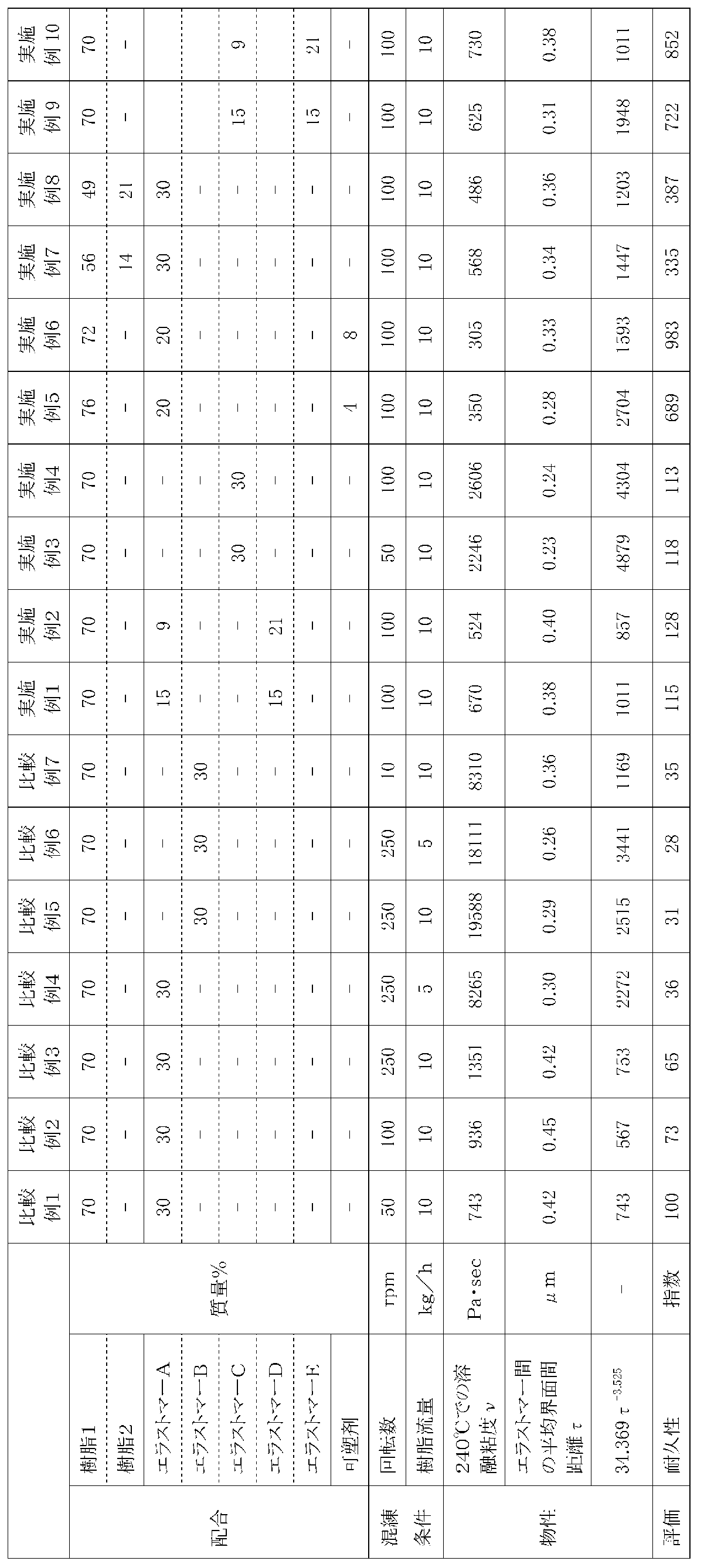
表1から、本発明に従う式(1)の関係を満たす樹脂組成物を骨格部材として用いた実施例のタイヤは、耐久性が大幅に向上していることが分かる。
1:非空気入りタイヤ、 2:ホイール部、 2a:装着筒部、 2b:リブ、 2c:外装筒部、 3:連結部材、 3a:内側部、 3b:外側部、 4:外筒、 5:トレッド部材、 6:内筒、 7:タイヤ部、 8:ボス、 10:非空気入りタイヤ、 11:ホイール部、 12:内筒、 13:外筒、 14:リング部材、 15:連結部材、 16:トレッド部材、 17:装着筒部、 18:外リング部、 19:リブ、 21:第1弾性連結板(連結部材)、 21a:一端部、 21b:他端部、 21c:中間部分、 21d~21f:湾曲部、 22:第2弾性連結板(連結部材)、 22a:一端部、 22b:他端部、 22c:中間部分、 22d~22f:湾曲部、 23:連結部材、 25:接着層
Claims (12)
- ポリアミド樹脂と、ガラス転移点が25℃以下のエラストマーと、を含有し、
240℃での溶融粘度ν(Pa・sec)とエラストマー間の平均界面間距離τ(μm)とが下記式(1):
ν<34.369τ-3.525 ・・・ (1)
の関係を満たす樹脂組成物を用いたことを特徴とする、タイヤ。 - 前記ポリアミド樹脂が、炭素数6~20の脂肪族ジアミン及び炭素数10~20の脂肪族ジカルボン酸を重合させてなるポリアミド樹脂である、請求項1に記載のタイヤ。
- 前記エラストマーが、ポリエチレン、ポリプロピレン、エチレン-プロピレンゴム、エチレン-1-ブテン共重合体、ポリα-オレフィン、アクリルゴム及びスチレン-エチレン-ブチレン-スチレン共重合体からなる群から選択される少なくとも一種を含む、請求項1又は2に記載のタイヤ。
- 前記エラストマーの少なくとも一部に、無水マレイン酸が、共重合又はグラフトされている、請求項1~3のいずれか一項に記載のタイヤ。
- 前記エラストマーの少なくとも一部に、エポキシ末端アクリル酸エステルが、共重合又はグラフトされている、請求項1~3のいずれか一項に記載のタイヤ。
- 前記樹脂組成物が、前記ポリアミド樹脂を60~90質量%含む、請求項1~5のいずれか一項に記載のタイヤ。
- 前記エラストマーの10~50質量%が変性エラストマーであり、前記エラストマーの90~50質量%が未変性エラストマーである、請求項1~6のいずれか一項に記載のタイヤ。
- 前記樹脂組成物が、更に、可塑剤を1~20質量%含有する、請求項1~7のいずれか一項に記載のタイヤ。
- 前記可塑剤が、N-ブチルベンゼンスルホンアミド、2-エチルヘキシル-4-ヒドロキシベンゾエート、及びN-(2-ヒドロキシプロピル)ベンゼンスルホンアミドからなる群から選択される少なくとも一種を含む、請求項8に記載のタイヤ。
- 前記エラストマーは、230℃における2.16kg荷重下でのメルトフローレート(MFR)が15g/10min以上である、請求項1~9のいずれか一項に記載のタイヤ。
- 前記ポリアミド樹脂の60~90質量%が、240℃における2.16kg荷重下でのメルトフローレート(MFR)が50g/10min以下のポリアミド610であり、
前記ポリアミド樹脂の10~40質量%が、240℃における2.16kg荷重下でのメルトフローレート(MFR)が60g/10min以上のポリアミド610である、請求項1~10のいずれか一項に記載のタイヤ。 - 前記タイヤは、車軸に取り付けられるホイール部と、該ホイール部に外装される内筒と、該内筒をタイヤ径方向の外側から囲繞する外筒と、前記内筒と前記外筒の間にタイヤ周方向に沿って複数配置された、前記両筒同士を連結する連結部材と、前記外筒のタイヤ径方向外側に設けられたトレッド部材と、を具える非空気入りタイヤであって、
前記内筒、前記外筒及び前記連結部材が、前記樹脂組成物からなる、請求項1~11のいずれか一項に記載のタイヤ。
Priority Applications (4)
| Application Number | Priority Date | Filing Date | Title |
|---|---|---|---|
| EP17909168.1A EP3623172A4 (en) | 2017-05-11 | 2017-12-19 | TIRE |
| JP2019516889A JP7041671B2 (ja) | 2017-05-11 | 2017-12-19 | タイヤ |
| CN201780090642.7A CN110612217A (zh) | 2017-05-11 | 2017-12-19 | 轮胎 |
| US16/677,961 US11225108B2 (en) | 2017-05-11 | 2019-11-08 | Tire |
Applications Claiming Priority (2)
| Application Number | Priority Date | Filing Date | Title |
|---|---|---|---|
| JP2017-095030 | 2017-05-11 | ||
| JP2017095030 | 2017-05-11 |
Related Child Applications (1)
| Application Number | Title | Priority Date | Filing Date |
|---|---|---|---|
| US16/677,961 Continuation US11225108B2 (en) | 2017-05-11 | 2019-11-08 | Tire |
Publications (1)
| Publication Number | Publication Date |
|---|---|
| WO2018207398A1 true WO2018207398A1 (ja) | 2018-11-15 |
Family
ID=64104479
Family Applications (1)
| Application Number | Title | Priority Date | Filing Date |
|---|---|---|---|
| PCT/JP2017/045597 Ceased WO2018207398A1 (ja) | 2017-05-11 | 2017-12-19 | タイヤ |
Country Status (5)
| Country | Link |
|---|---|
| US (1) | US11225108B2 (ja) |
| EP (1) | EP3623172A4 (ja) |
| JP (1) | JP7041671B2 (ja) |
| CN (1) | CN110612217A (ja) |
| WO (1) | WO2018207398A1 (ja) |
Cited By (2)
| Publication number | Priority date | Publication date | Assignee | Title |
|---|---|---|---|---|
| JP2020059846A (ja) * | 2018-10-09 | 2020-04-16 | 東レ株式会社 | ポリアミド樹脂組成物およびそれを含む成形品 |
| JPWO2022065519A1 (ja) * | 2020-09-28 | 2022-03-31 |
Families Citing this family (2)
| Publication number | Priority date | Publication date | Assignee | Title |
|---|---|---|---|---|
| US11970031B2 (en) | 2019-02-13 | 2024-04-30 | Gallagher Corporation | Polyurethane gauge wheel tire |
| US11351818B2 (en) | 2020-07-14 | 2022-06-07 | Sun T. Hong | Spiral spring wheel |
Citations (7)
| Publication number | Priority date | Publication date | Assignee | Title |
|---|---|---|---|---|
| JP2000063572A (ja) * | 1998-08-21 | 2000-02-29 | Yokohama Rubber Co Ltd:The | 熱可塑性エラストマー組成物の製造方法およびそれを使用した空気入りタイヤ |
| JP2009513772A (ja) * | 2005-10-27 | 2009-04-02 | エクソンモービル ケミカル パテンツ,インコーポレイティド | 熱可塑性エラストマー組成物及びその製造方法 |
| JP2010036883A (ja) * | 2008-07-09 | 2010-02-18 | Bridgestone Corp | 非空気入りタイヤ |
| JP2010037465A (ja) * | 2008-08-06 | 2010-02-18 | Yokohama Rubber Co Ltd:The | 熱可塑性エラストマー組成物およびそれを用いた空気入りタイヤ |
| JP2010516835A (ja) | 2007-01-18 | 2010-05-20 | 横浜ゴム株式会社 | 優れた伸長性及び屈曲疲労を有するポリアミド樹脂組成物並びにそれを使用する空気入りタイヤ及びホース |
| JP2010132850A (ja) * | 2008-11-05 | 2010-06-17 | Yokohama Rubber Co Ltd:The | 熱可塑性樹脂組成物、それを用いた積層体およびタイヤ |
| JP2015155303A (ja) * | 2015-05-18 | 2015-08-27 | 株式会社ブリヂストン | タイヤ |
Family Cites Families (21)
| Publication number | Priority date | Publication date | Assignee | Title |
|---|---|---|---|---|
| DE4131908C2 (de) * | 1991-09-25 | 1999-05-12 | Du Pont | Polyamid/Polyolefin-Gemische und deren Verwendung |
| JPH06116461A (ja) * | 1992-10-09 | 1994-04-26 | Denki Kagaku Kogyo Kk | 樹脂組成物 |
| DE69511615T2 (de) * | 1994-05-20 | 1999-12-09 | Ube Industries, Ltd. | Polyamidmatrix mit darin dispergierten Polyolefinkörnern enthaltendes Harzverbundmaterial |
| JP3217239B2 (ja) | 1995-01-23 | 2001-10-09 | 横浜ゴム株式会社 | タイヤ用ポリマー組成物およびそれを使用した空気入りタイヤ |
| JP3098191B2 (ja) | 1996-06-27 | 2000-10-16 | 横浜ゴム株式会社 | ゴム・熱可塑性エラストマー積層体 |
| JP4942253B2 (ja) | 2000-04-11 | 2012-05-30 | 横浜ゴム株式会社 | 加工性が改良された熱可塑性エラストマー組成物およびそれを用いたタイヤ |
| CN102675662B (zh) | 2006-03-03 | 2014-08-20 | 横滨橡胶株式会社 | 弹性体组合物和其制造方法、及使用该弹性体组合物的充气轮胎 |
| JP5251347B2 (ja) * | 2008-08-07 | 2013-07-31 | 横浜ゴム株式会社 | 熱可塑性エラストマー組成物並びにその製造方法及びそれを用いた空気入りタイヤ |
| US8378035B2 (en) * | 2009-08-03 | 2013-02-19 | The Yokohama Rubber Co., Ltd. | Thermoplastic elastomer composition |
| EP3251874B1 (en) * | 2010-08-25 | 2019-02-20 | Bridgestone Corporation | Tire, and tire manufacturing method |
| JP5879089B2 (ja) * | 2011-10-20 | 2016-03-08 | 株式会社ブリヂストン | 非空気入りタイヤの製造方法 |
| CN103997927B (zh) * | 2011-12-27 | 2017-06-09 | Ykk株式会社 | 拉链用成型部件及具备该部件的拉链 |
| JP2014125079A (ja) | 2012-12-26 | 2014-07-07 | Bridgestone Corp | 非空気入りタイヤ |
| JP6076776B2 (ja) | 2013-02-28 | 2017-02-08 | 株式会社ブリヂストン | タイヤ |
| CN106660395B (zh) * | 2014-06-16 | 2019-03-01 | 株式会社普利司通 | 轮胎 |
| JP6704689B2 (ja) | 2014-07-11 | 2020-06-03 | 株式会社クラレ | 樹脂組成物、多層構造体、多層シート、ブロー成形容器及び熱成形容器 |
| CN104292622B (zh) * | 2014-09-25 | 2016-07-06 | 广东银禧科技股份有限公司 | 一种低流痕、低熔接痕的聚丙烯组合物及其制备方法 |
| CN104804659B (zh) * | 2015-05-11 | 2017-08-29 | 上海天洋热熔粘接材料股份有限公司 | 一种用于粘接金属与非极性材料的热熔胶膜及其制备方法 |
| US10995207B2 (en) | 2015-09-17 | 2021-05-04 | Eneos Corporation | Thermoplastic elastomer composition and method for producing the same |
| EP3409725B1 (en) | 2016-01-29 | 2020-07-15 | Bridgestone Corporation | Tire |
| JP2018086864A (ja) | 2016-11-28 | 2018-06-07 | 株式会社ブリヂストン | 非空気入りタイヤ |
-
2017
- 2017-12-19 JP JP2019516889A patent/JP7041671B2/ja active Active
- 2017-12-19 WO PCT/JP2017/045597 patent/WO2018207398A1/ja not_active Ceased
- 2017-12-19 CN CN201780090642.7A patent/CN110612217A/zh active Pending
- 2017-12-19 EP EP17909168.1A patent/EP3623172A4/en not_active Withdrawn
-
2019
- 2019-11-08 US US16/677,961 patent/US11225108B2/en active Active
Patent Citations (7)
| Publication number | Priority date | Publication date | Assignee | Title |
|---|---|---|---|---|
| JP2000063572A (ja) * | 1998-08-21 | 2000-02-29 | Yokohama Rubber Co Ltd:The | 熱可塑性エラストマー組成物の製造方法およびそれを使用した空気入りタイヤ |
| JP2009513772A (ja) * | 2005-10-27 | 2009-04-02 | エクソンモービル ケミカル パテンツ,インコーポレイティド | 熱可塑性エラストマー組成物及びその製造方法 |
| JP2010516835A (ja) | 2007-01-18 | 2010-05-20 | 横浜ゴム株式会社 | 優れた伸長性及び屈曲疲労を有するポリアミド樹脂組成物並びにそれを使用する空気入りタイヤ及びホース |
| JP2010036883A (ja) * | 2008-07-09 | 2010-02-18 | Bridgestone Corp | 非空気入りタイヤ |
| JP2010037465A (ja) * | 2008-08-06 | 2010-02-18 | Yokohama Rubber Co Ltd:The | 熱可塑性エラストマー組成物およびそれを用いた空気入りタイヤ |
| JP2010132850A (ja) * | 2008-11-05 | 2010-06-17 | Yokohama Rubber Co Ltd:The | 熱可塑性樹脂組成物、それを用いた積層体およびタイヤ |
| JP2015155303A (ja) * | 2015-05-18 | 2015-08-27 | 株式会社ブリヂストン | タイヤ |
Non-Patent Citations (2)
| Title |
|---|
| FUKUI, TAKAMASA ET AL.: "Elastic-plastic analysis of rubber-toughened nylon by two- dimensional finite element method", JAPANESE JOURNAL OF POLYMER SCIENCE AND TECHNOLOGY, vol. 47, no. 4, April 1990 (1990-04-01), pages 315 - 320, XP055558505 * |
| See also references of EP3623172A4 |
Cited By (4)
| Publication number | Priority date | Publication date | Assignee | Title |
|---|---|---|---|---|
| JP2020059846A (ja) * | 2018-10-09 | 2020-04-16 | 東レ株式会社 | ポリアミド樹脂組成物およびそれを含む成形品 |
| JPWO2022065519A1 (ja) * | 2020-09-28 | 2022-03-31 | ||
| WO2022065519A1 (ja) * | 2020-09-28 | 2022-03-31 | 香織 田中 | 移動体 |
| JP7225519B2 (ja) | 2020-09-28 | 2023-02-21 | 香織 田中 | 移動体 |
Also Published As
| Publication number | Publication date |
|---|---|
| US11225108B2 (en) | 2022-01-18 |
| EP3623172A1 (en) | 2020-03-18 |
| US20200070576A1 (en) | 2020-03-05 |
| CN110612217A (zh) | 2019-12-24 |
| JP7041671B2 (ja) | 2022-03-24 |
| JPWO2018207398A1 (ja) | 2020-03-19 |
| EP3623172A4 (en) | 2020-12-02 |
Similar Documents
| Publication | Publication Date | Title |
|---|---|---|
| CN103370209B (zh) | 轮胎 | |
| US11225108B2 (en) | Tire | |
| KR101600087B1 (ko) | 열가소성 엘라스토머 조성물 및 이를 사용하는 공기식 타이어 | |
| CN108495895B (zh) | 轮胎 | |
| WO2017203766A1 (ja) | タイヤ | |
| WO2018211734A1 (ja) | タイヤ | |
| JPWO2019093212A1 (ja) | 非空気入りタイヤ | |
| JP6664895B2 (ja) | タイヤ | |
| JP6820001B2 (ja) | タイヤ | |
| JP6253968B2 (ja) | タイヤインナーライナー及び空気入りタイヤ | |
| US9803084B2 (en) | Resin composition for fuel tubes, and fuel tube | |
| JP5960875B2 (ja) | タイヤ | |
| JP6649678B2 (ja) | タイヤ | |
| JP2018002953A (ja) | 加硫ゴム組成物 | |
| JPH09143366A (ja) | 熱可塑性エラストマー組成物およびその製造方法ならびに低透過性ホース | |
| JP7796731B2 (ja) | 非空気入りタイヤ | |
| JP4933690B2 (ja) | ビードフィラーゴム組成物及びこれを用いた空気入りタイヤ | |
| WO2006129452A1 (ja) | ジョイントブーツ | |
| JP2020002331A (ja) | 樹脂組成物及び非空気入りタイヤ | |
| JP2018104574A (ja) | 動的架橋物の製造方法、及びタイヤ用耐空気透過性フィルムの製造方法 | |
| JP2008215493A (ja) | ジョイントブーツ |
Legal Events
| Date | Code | Title | Description |
|---|---|---|---|
| 121 | Ep: the epo has been informed by wipo that ep was designated in this application |
Ref document number: 17909168 Country of ref document: EP Kind code of ref document: A1 |
|
| ENP | Entry into the national phase |
Ref document number: 2019516889 Country of ref document: JP Kind code of ref document: A |
|
| NENP | Non-entry into the national phase |
Ref country code: DE |
|
| ENP | Entry into the national phase |
Ref document number: 2017909168 Country of ref document: EP Effective date: 20191211 |