WO2018207471A1 - Dispositif de commande, système de commande, procédé de commande et programme - Google Patents
Dispositif de commande, système de commande, procédé de commande et programme Download PDFInfo
- Publication number
- WO2018207471A1 WO2018207471A1 PCT/JP2018/010984 JP2018010984W WO2018207471A1 WO 2018207471 A1 WO2018207471 A1 WO 2018207471A1 JP 2018010984 W JP2018010984 W JP 2018010984W WO 2018207471 A1 WO2018207471 A1 WO 2018207471A1
- Authority
- WO
- WIPO (PCT)
- Prior art keywords
- speckle
- laser light
- image
- control
- standard sample
- Prior art date
- Legal status (The legal status is an assumption and is not a legal conclusion. Google has not performed a legal analysis and makes no representation as to the accuracy of the status listed.)
- Ceased
Links
Images








Classifications
-
- A—HUMAN NECESSITIES
- A61—MEDICAL OR VETERINARY SCIENCE; HYGIENE
- A61B—DIAGNOSIS; SURGERY; IDENTIFICATION
- A61B5/00—Measuring for diagnostic purposes; Identification of persons
- A61B5/0033—Features or image-related aspects of imaging apparatus, e.g. for MRI, optical tomography or impedance tomography apparatus; Arrangements of imaging apparatus in a room
- A61B5/004—Features or image-related aspects of imaging apparatus, e.g. for MRI, optical tomography or impedance tomography apparatus; Arrangements of imaging apparatus in a room adapted for image acquisition of a particular organ or body part
- A61B5/0042—Features or image-related aspects of imaging apparatus, e.g. for MRI, optical tomography or impedance tomography apparatus; Arrangements of imaging apparatus in a room adapted for image acquisition of a particular organ or body part for the brain
-
- A—HUMAN NECESSITIES
- A61—MEDICAL OR VETERINARY SCIENCE; HYGIENE
- A61B—DIAGNOSIS; SURGERY; IDENTIFICATION
- A61B5/00—Measuring for diagnostic purposes; Identification of persons
- A61B5/0059—Measuring for diagnostic purposes; Identification of persons using light, e.g. diagnosis by transillumination, diascopy, fluorescence
- A61B5/0062—Arrangements for scanning
- A61B5/0066—Optical coherence imaging
-
- A—HUMAN NECESSITIES
- A61—MEDICAL OR VETERINARY SCIENCE; HYGIENE
- A61B—DIAGNOSIS; SURGERY; IDENTIFICATION
- A61B5/00—Measuring for diagnostic purposes; Identification of persons
- A61B5/0059—Measuring for diagnostic purposes; Identification of persons using light, e.g. diagnosis by transillumination, diascopy, fluorescence
- A61B5/0077—Devices for viewing the surface of the body, e.g. camera, magnifying lens
-
- A—HUMAN NECESSITIES
- A61—MEDICAL OR VETERINARY SCIENCE; HYGIENE
- A61B—DIAGNOSIS; SURGERY; IDENTIFICATION
- A61B5/00—Measuring for diagnostic purposes; Identification of persons
- A61B5/02—Detecting, measuring or recording for evaluating the cardiovascular system, e.g. pulse, heart rate, blood pressure or blood flow
- A61B5/026—Measuring blood flow
- A61B5/0261—Measuring blood flow using optical means, e.g. infrared light
-
- A—HUMAN NECESSITIES
- A61—MEDICAL OR VETERINARY SCIENCE; HYGIENE
- A61B—DIAGNOSIS; SURGERY; IDENTIFICATION
- A61B5/00—Measuring for diagnostic purposes; Identification of persons
- A61B5/40—Detecting, measuring or recording for evaluating the nervous system
- A61B5/4058—Detecting, measuring or recording for evaluating the nervous system for evaluating the central nervous system
- A61B5/4064—Evaluating the brain
-
- A—HUMAN NECESSITIES
- A61—MEDICAL OR VETERINARY SCIENCE; HYGIENE
- A61B—DIAGNOSIS; SURGERY; IDENTIFICATION
- A61B5/00—Measuring for diagnostic purposes; Identification of persons
- A61B5/68—Arrangements of detecting, measuring or recording means, e.g. sensors, in relation to patient
- A61B5/6846—Arrangements of detecting, measuring or recording means, e.g. sensors, in relation to patient specially adapted to be brought in contact with an internal body part, i.e. invasive
- A61B5/6847—Arrangements of detecting, measuring or recording means, e.g. sensors, in relation to patient specially adapted to be brought in contact with an internal body part, i.e. invasive mounted on an invasive device
-
- G—PHYSICS
- G02—OPTICS
- G02B—OPTICAL ELEMENTS, SYSTEMS OR APPARATUS
- G02B21/00—Microscopes
- G02B21/0004—Microscopes specially adapted for specific applications
- G02B21/002—Scanning microscopes
- G02B21/0024—Confocal scanning microscopes (CSOMs) or confocal "macroscopes"; Accessories which are not restricted to use with CSOMs, e.g. sample holders
- G02B21/0028—Confocal scanning microscopes (CSOMs) or confocal "macroscopes"; Accessories which are not restricted to use with CSOMs, e.g. sample holders specially adapted for specific applications, e.g. for endoscopes, ophthalmoscopes, attachments to conventional microscopes
-
- G—PHYSICS
- G02—OPTICS
- G02B—OPTICAL ELEMENTS, SYSTEMS OR APPARATUS
- G02B21/00—Microscopes
- G02B21/0004—Microscopes specially adapted for specific applications
- G02B21/002—Scanning microscopes
- G02B21/0024—Confocal scanning microscopes (CSOMs) or confocal "macroscopes"; Accessories which are not restricted to use with CSOMs, e.g. sample holders
- G02B21/0032—Optical details of illumination, e.g. light-sources, pinholes, beam splitters, slits, fibers
-
- G—PHYSICS
- G02—OPTICS
- G02B—OPTICAL ELEMENTS, SYSTEMS OR APPARATUS
- G02B21/00—Microscopes
- G02B21/0004—Microscopes specially adapted for specific applications
- G02B21/002—Scanning microscopes
- G02B21/0024—Confocal scanning microscopes (CSOMs) or confocal "macroscopes"; Accessories which are not restricted to use with CSOMs, e.g. sample holders
- G02B21/008—Details of detection or image processing, including general computer control
-
- A—HUMAN NECESSITIES
- A61—MEDICAL OR VETERINARY SCIENCE; HYGIENE
- A61B—DIAGNOSIS; SURGERY; IDENTIFICATION
- A61B2576/00—Medical imaging apparatus involving image processing or analysis
- A61B2576/02—Medical imaging apparatus involving image processing or analysis specially adapted for a particular organ or body part
- A61B2576/026—Medical imaging apparatus involving image processing or analysis specially adapted for a particular organ or body part for the brain
-
- A—HUMAN NECESSITIES
- A61—MEDICAL OR VETERINARY SCIENCE; HYGIENE
- A61B—DIAGNOSIS; SURGERY; IDENTIFICATION
- A61B5/00—Measuring for diagnostic purposes; Identification of persons
- A61B5/0059—Measuring for diagnostic purposes; Identification of persons using light, e.g. diagnosis by transillumination, diascopy, fluorescence
- A61B5/0082—Measuring for diagnostic purposes; Identification of persons using light, e.g. diagnosis by transillumination, diascopy, fluorescence adapted for particular medical purposes
-
- A—HUMAN NECESSITIES
- A61—MEDICAL OR VETERINARY SCIENCE; HYGIENE
- A61B—DIAGNOSIS; SURGERY; IDENTIFICATION
- A61B5/00—Measuring for diagnostic purposes; Identification of persons
- A61B5/145—Measuring characteristics of blood in vivo, e.g. gas concentration or pH-value ; Measuring characteristics of body fluids or tissues, e.g. interstitial fluid or cerebral tissue
- A61B5/1455—Measuring characteristics of blood in vivo, e.g. gas concentration or pH-value ; Measuring characteristics of body fluids or tissues, e.g. interstitial fluid or cerebral tissue using optical sensors, e.g. spectral photometrical oximeters
-
- G—PHYSICS
- G02—OPTICS
- G02B—OPTICAL ELEMENTS, SYSTEMS OR APPARATUS
- G02B23/00—Telescopes, e.g. binoculars; Periscopes; Instruments for viewing the inside of hollow bodies; Viewfinders; Optical aiming or sighting devices
- G02B23/24—Instruments or systems for viewing the inside of hollow bodies, e.g. fibrescopes
-
- G—PHYSICS
- G16—INFORMATION AND COMMUNICATION TECHNOLOGY [ICT] SPECIALLY ADAPTED FOR SPECIFIC APPLICATION FIELDS
- G16H—HEALTHCARE INFORMATICS, i.e. INFORMATION AND COMMUNICATION TECHNOLOGY [ICT] SPECIALLY ADAPTED FOR THE HANDLING OR PROCESSING OF MEDICAL OR HEALTHCARE DATA
- G16H30/00—ICT specially adapted for the handling or processing of medical images
- G16H30/40—ICT specially adapted for the handling or processing of medical images for processing medical images, e.g. editing
Definitions
- This technology relates to a control device, a control system, a control method, and a program that can be applied to observation of a living tissue.
- Patent Document 1 discloses an analyzer that analyzes blood flow and the like of a living tissue based on speckle data obtained by irradiating a laser beam.
- the laser beam irradiated onto the analysis object is imaged by the imaging optical system, and a speckle image is taken by the imaging element.
- the numerical aperture of the imaging optical system is controlled based on the speckle contrast calculated based on the speckle image.
- the spec contrast can be increased and the measurement accuracy of blood flow and the like can be improved (paragraph [0056] FIGS. 1 and 6 in the specification of Patent Document 1).
- an object of the present technology is to provide a control device, a control system, a control method, and a program capable of observing a living tissue or the like with high accuracy.
- a control device includes a signal generation unit.
- the signal generation unit generates speckle data based on an image signal of a subject photographed using laser light for illumination, and controls the output of the laser light based on the generated speckle data Is generated.
- control device is configured to control the output of the laser light source based on speckle data calculated from the image signal of the subject, variations in the output of the laser light source can be suppressed, and biological tissue and the like can be accurately detected. It becomes possible to observe.
- the subject may include an observation object and a standard sample for calibration, and the signal generation unit may generate the speckle data based on an image signal of the standard sample. Thereby, the output of the laser light source or its variation can be detected with high accuracy.
- the control device may further include a display control unit that displays a speckle contrast image of the subject on the display unit.
- a display control unit that displays a speckle contrast image of the subject on the display unit.
- the signal generator When the speckle data is less than a first threshold, the signal generator generates a control signal for increasing or decreasing the output of the laser light source so that the speckle data is equal to or greater than the first threshold. It may be configured to generate. As a result, the laser light source can be controlled to an output that provides a desired observation image.
- the signal generation unit increases or decreases the output of the laser light source by a predetermined amount until the speckle data becomes equal to or higher than the first threshold.
- the control may be repeatedly executed, and an error signal may be generated when the increase amount or decrease amount of the output of the laser light source exceeds the second threshold value. Thereby, the presence or absence of abnormality of the laser light source can be detected.
- the speckle data may include speckle contrast
- the signal generation unit may be configured to generate the control signal based on the speckle contrast.
- the image signal includes a plurality of pixel signals each including luminance information
- the speckle data includes a difference between a maximum luminance and a minimum luminance
- the signal generation unit includes the minimum luminance and the maximum luminance.
- the control signal may be generated based on the difference.
- a control system includes an illumination unit, a standard sample for calibration, an imaging unit, and a control device.
- the illuminating unit includes a laser light source that irradiates the observation target with laser light and a laser driver that adjusts the output of the laser light source.
- the standard sample is configured to be arranged at a position where the laser beam is irradiated.
- the imaging unit acquires images of an observation object and a standard sample that have been irradiated with the laser light.
- the control device includes a signal generation unit.
- the signal generation unit generates speckle data from individual pixel signals constituting the image of the standard sample, and generates a control signal for controlling the laser driver based on the generated speckle data.
- the control system may further include a display unit.
- the control device further includes a display control unit that displays a speckle contrast image of the observation object on the display unit.
- the standard sample is typically a light diffusing optical element.
- the standard sample may be a diffusion plate or a surgical drape.
- the control system may further include a holding unit that holds the standard sample.
- the holding unit selectively selects a first state in which the standard sample is disposed within the photographing region of the photographing unit and a second state in which the standard sample is disposed outside the photographing region of the photographing unit. Configured to switch.
- the imaging unit may include a first camera that images the observation object and a second camera that images the standard sample.
- the control system may be configured as an endoscope or a microscope.
- a control method is a control method executed by a computer system, and includes generating speckle data based on an image signal of a subject photographed using laser light for illumination. Based on the generated speckle data, a control signal for controlling the output of the laser light source that irradiates the laser light is generated.
- a program causes a computer system to execute the following steps. Generating speckle data based on an image signal of a subject photographed using laser light for illumination; Generating a control signal for controlling the output of the laser light source for irradiating the laser beam based on the generated speckle data.
- 1 is a block diagram schematically showing a typical system configuration of a speckle blood flow imaging device. It is an example of the image which image
- 1 is a schematic configuration diagram illustrating a control system according to a first embodiment of the present technology. It is a functional block diagram of the said control system. It is an example of a speckle image captured by irradiating a model simulating the brain with laser light. It is explanatory drawing of the calculation unit of a speckle contrast. It is a figure which shows an example of a speckle contrast image. It is an experimental result when speckle contrast is measured using three LDs of the same type.
- the correspondence between the speckle image and the spectrum of the LD is shown. It is an example which showed the relationship between LD electric current and speckle contrast. It is a flowchart which shows the basic operation
- the control system of the present embodiment is applied to observation of living tissue.
- an example of application to blood flow observation of the brain that can be used for brain surgery, for example, will be described.
- a speckle blood flow imaging apparatus that irradiates a blood vessel with a laser beam and displays a blood flow using a speckle image has been proposed.
- a speckle image is an image obtained by irradiating laser light having a specific wavelength with high coherence, and the wavelength may be red, blue, green, infrared or ultraviolet, Near infrared is desirable for blood flow observation.
- the speckle blood flow imaging apparatus irradiates a scattering substance (for example, blood flowing in a blood vessel) in a fluid with a highly coherent laser beam, and speckles that are interference light due to the scattering substance become difficult to see due to the flow.
- speckle is defined as speckle contrast, for example, the difference between a bright part and a dark part.
- the speckle blood flow imaging device uses the phenomenon that the speckle contrast increases when there is no flow, and the speckle contrast decreases when there is a flow. Is a device for observing.
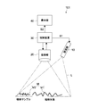
- FIG. 1 is a block diagram schematically showing a typical system configuration of a speckle blood flow imaging apparatus.
- a speckle blood flow imaging apparatus 100 shown in the figure processes a light source 1 that irradiates a subject F with laser light L as illumination light, a camera 2 that acquires a speckle image of the subject F, and the speckle image.
- An image processing unit 3 that calculates speckle contrast, a display unit 4 that can display a speckle contrast image, and a laser driver 5 that controls the output of the illumination unit 1 based on the speckle contrast.
- the speckle contrast image is an image obtained by performing signal processing on the speckle image based on speckle contrast calculation and performing image processing as an image suitable for the display unit 4. This process is combined with image processing. A method for calculating speckle contrast will be described later.
- FIG. 2 An example of a speckle contrast image obtained by imaging a blood vessel in the brain is shown in FIG. 2 in comparison with a clear vision image and an ICG image.
- A is a clear vision image
- B is an ICG image
- C is a speckle contrast image.
- the clear vision image is, for example, white light emitted from a mercury lamp, a xenon lamp, or the like, or white light formed by laser light or LED composed of red, blue, and green (which may include infrared and ultraviolet). It is an image obtained by irradiating light.
- the speckle blood flow imaging device uses the fact that the speckle image generated by scattering becomes difficult to see due to the flow (motion) of the scattering material, and thus the coherence (coherence) of the original laser light source. )is important.
- the coherence of laser light increases when the spectral width is narrow. Therefore, the speckle blood flow imaging apparatus requires a laser having a narrow spectral width.
- such a semiconductor laser has a problem that the spectrum width becomes wider or narrower when the amount of current is changed in order to adjust the light output.
- a dedicated measuring device for measuring the spectrum width is required.
- the entire system becomes large, and There was also a problem that the configuration was complicated.
- a speckle blood flow imaging apparatus using a laser light source provides a control system that can grasp the state of the light source by a simple method and stably acquire a high-precision speckle contrast image. The purpose is to do. The details will be described below.
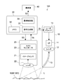
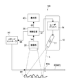
- FIG. 3 is a schematic configuration diagram illustrating the control system 101 according to the first embodiment of the present technology.
- FIG. 4 is a functional block diagram of the control system 101 shown in FIG.
- the control system 101 includes an illumination unit 10, an imaging unit 20, and a control device 30.
- the control system 101 of this embodiment further includes a display unit 40.
- the illumination unit 10 irradiates the subject M with a laser beam L used as illumination when acquiring a speckle image of the subject M.
- the illumination unit 10 includes a laser light source 11, an illumination lens 12, an optical fiber 13, and a laser driver 14.
- the illumination unit 10 may further include a temperature control unit (not shown) that keeps the laser light source 11 at a predetermined temperature.
- the laser light source 11 generates a laser beam L irradiated to the subject M.
- the laser light source 11 is composed of a laser diode (LD), for example, a Fabry-Perot type semiconductor laser.
- the wavelength of the laser light L emitted from the laser light source 11 is not particularly limited, and may be a visible light wavelength such as red, blue, or green, or may be a wavelength in the infrared or ultraviolet region. An appropriate laser wavelength that can obtain an image is employed.
- a near infrared laser light source is suitable as the laser light source 11.
- the illumination lens 12 condenses the laser light emitted from the laser light source 11 on the incident end of the optical fiber 13.
- the optical fiber 13 transmits the laser beam L incident on the incident end to the exit end, and irradiates the subject M from the exit end.
- the irradiation position and irradiation direction of the laser light L1 can be arbitrarily adjusted as compared with the case where the subject M is directly irradiated with the laser light L from the laser light source 11. Become.
- the optical fiber 13 may be omitted as necessary.
- the illumination lens 12 is configured to adjust the irradiation range of the laser light L so that the laser light L emitted from the laser light source 11 is applied to a predetermined region of the subject M.
- the laser driver 14 adjusts the output of the laser light source 11. Typically, the laser driver 14 adjusts the output of the laser light source 11 by adjusting the drive current of the laser light source 11.
- the adjustment range of the output of the laser light source 11 is appropriately set according to the type and specification of the laser light source 11 and is, for example, in the range of 200 mW to 400 mW.
- the laser driver 14 is driven based on a control signal S1 (see FIG. 4) output from the control device 30.
- the subject M includes an observation object M1 including a blood vessel such as a patient's brain and a standard sample M2 for calibration.
- an optical element made of a uniform medium having a light diffusibility that can reflect the laser light L toward the imaging unit 20 is typically used.
- the standard sample M2 is referred to when the output of the laser light source 11 is evaluated.
- a light-reflective diffuser is used as the standard sample M2, but other members such as a surgical drape may also be used as the standard sample M2, as will be described later.
- the standard sample M2 is disposed at a position where it can be irradiated with the laser light L, typically in the vicinity of the observation object M1.
- the standard sample M2 is regularly arranged in the imaging region, but may be configured to be arranged in the imaging region at an arbitrary timing as will be described later.
- the imaging unit 20 acquires an image (speckle image) of the subject M by photographing the observation object M1 and the standard sample M2 irradiated with the laser light L.
- the speckle image of the subject M includes a speckle image of the observation object M1 and a speckle image of the standard sample M2.
- the speckle image of the standard sample M2 is hereinafter also referred to as a standard speckle image.
- the imaging unit 20 includes an image sensor 21, a lens system 22, and a camera controller 23 as shown in FIG.
- the image sensor 21 images the subject M illuminated with the laser light L, and outputs it to the control device 30 as an image signal Vs (see FIG. 4).
- a CCD (Charge-Coupled Device) sensor, a CMOS (Complementary Metal-Oxide-Semiconductor) sensor, or the like is used as the image sensor that constitutes the image sensor 21.
- CMOS Complementary Metal-Oxide-Semiconductor
- the lens system 22 forms a reflection image of the laser light L from the subject M on the image sensor of the image sensor 21.
- the lens system 22 is typically composed of a plurality of optical lenses and diaphragms, and is configured to be movable in the optical axis direction via the camera controller 23.
- the camera controller 23 drives the image sensor 21 and executes image capture control from the image sensor 21 based on a control command S3 from the control device 30 (see FIG. 4).
- the camera controller 23 is configured to be able to control shooting parameters of the imaging unit 20.
- the shooting parameters related to shooting include arbitrary parameters related to shooting of the subject M.
- the shooting parameters include arbitrary parameters such as exposure time, gain of the image sensor, focal length, angle of view, F value, and the like.
- the camera controller 23 may be configured as a part of the control device 30.
- the observation object M1 and the standard sample M2 are photographed simultaneously by a single camera (image sensor 21). Therefore, the individual pixel signals constituting the image signal Vs of the subject M include a pixel signal related to the observation object M2 and a pixel signal related to the standard sample M2. As will be described later, the observation object M1 and the standard sample M2 may be photographed separately (at different times) by one camera, or may be photographed simultaneously (at the same time) by two cameras. Good.
- the control device 30 has hardware necessary for the configuration of the computer, such as a CPU, a ROM, a RAM, and an HDD.
- the control method according to the present technology is executed by the CPU loading a program according to the present technology recorded in advance in a ROM or the like into the RAM and executing the program.
- the control device 30 can be realized by an arbitrary computer such as a PC (Personal Computer).
- control device 30 is not limited, and devices such as an FPGA (Field Programmable Gate Array), an image processing IC (Integrated Circuit), and other ASIC (Application Specific Integrated Circuit) may be used.
- FPGA Field Programmable Gate Array
- image processing IC Integrated Circuit
- ASIC Application Specific Integrated Circuit
- the control device 30 controls the illumination unit 10, the imaging unit 20, and the display unit 40.
- a signal generation unit 31 and a display control unit 33 as functional blocks are configured by the CPU executing a predetermined program.
- a memory 32 is configured by the ROM of the control device 30 or the like.
- dedicated hardware such as an IC (integrated circuit) may be used to realize each block.
- the program is installed in the control device 30 via various recording media, for example. Alternatively, program installation may be executed via the Internet or the like.
- the signal generation unit 31 generates speckle data based on the image signal of the subject M photographed using the laser light L for illumination, and irradiates the laser light L based on the generated speckle data.
- a control signal S1 for controlling the output of is generated.
- the signal generation unit 31 generates speckle data from individual pixel signals (that is, standard speckle images) constituting the image of the standard sample M2, and the laser driver 14 is activated based on the generated speckle data.
- a control signal S1 to be controlled is generated.
- the speckle data includes speckle contrast, and the signal generation unit 31 generates the control signal S1 based on the speckle contrast.
- the memory 32 is composed of a frame memory capable of storing the image signal Vs input from the imaging unit 20.
- the memory 32 includes a non-volatile memory that fixedly stores calculation parameters necessary for generation of speckle contrast (speckle data) in the signal generation unit 31.
- the display control unit 33 generates a speckle contrast image of the observation object M1 or the standard sample M2 based on the speckle data of the subject M generated by the signal generation unit 31, and displays it on the display unit 40.
- the signal S2 (see FIG. 4) is output to the display unit 40.
- the display control unit 33 generates a speckle contrast image at a timing of 60 sheets (60 Hz) per second.
- the display control unit 33 is configured to display the output adjustment completion information of the laser light source 11 and error information of the laser light source 11 on the display unit 40 as will be described later.
- the display control unit 33 may be configured to be able to display the speckle image, clear vision image, ICG image, and the like of the subject M on the display unit 40 in addition to the speckle contrast image of the subject M. A plurality of these images may be selectively displayed at the same time, or may be individually switched and displayed.
- the control device 30 may be configured to be able to switch each of these illuminations in time series (field sequential). .
- the display unit 40 is not particularly limited, and may be a monitor device such as a liquid crystal display (LCD) or an organic electroluminescence display, or a viewer built in an eyepiece for an endoscope or a microscope.
- a monitor device such as a liquid crystal display (LCD) or an organic electroluminescence display, or a viewer built in an eyepiece for an endoscope or a microscope.
- FIG. 5 is an example of a speckle image captured by irradiating a model simulating the brain with laser light.
- a hollow tube that imitates a blood vessel through which fluid flows in the dotted line, and a fluid containing a scattering material that imitates blood can flow inside.
- an area indicated by a white square at the upper left indicates, for example, a unit of image processing.
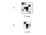
- FIG. 6 explains the calculation unit of speckle contrast.
- the signal generator 32 generates speckle contrast, for example, as follows.
- the unit of the pixel used for the calculation of speckle contrast may be 3 ⁇ 3 as shown in FIG. 6B, or another unit.
- speckles can be clearly seen and the variance of each pixel value increases, that is, the standard deviation also increases, so the value of K increases.
- the speckle is disturbed (not seen), so that the variance of each pixel value becomes small, that is, the standard deviation becomes small, so the value of K becomes small.
- the K value is small (darkens).
- FIG. 7 shows an example of a speckle contrast image. In the figure, the black lined portion indicates that there is blood flow.
- Speckle contrast can be calculated using only the vertical and horizontal size of the image across the entire screen as described above.
- the resulting image is a speckle contrast image.
- a diffuser plate is used as a standard sample. The diffusion plate is suitable for such a purpose.
- speckle images obtained by irradiating a standard sample with laser light may partially increase or decrease the speckle contrast value (K value).
- K value speckle contrast value
- Various methods can be considered for this method. For example, the average value of speckle contrast values (speckle contrast values) of the entire screen is used as the speckle contrast, or the spec of the area that is uniformly illuminated. The average value of the contrast values may be used as a representative value.
- the magnitude of speckle contrast depends on the state of the light source, the optical system, the lens aperture, the subject, etc. Especially, since the laser light source tends to vary in its oscillation spectrum, the speckle contrast obtained is also the same as that of the laser light source. Susceptible to fluctuations in the oscillation spectrum.
- FIGS. 8A and 8B show experimental results when speckle contrast is measured using three LDs of the same type.
- FIG. 8A shows an example of measurement with three LDs (# 11, # 12, # 13) of the same manufacturer
- FIG. 8B shows measurement with three LDs (# 21, # 22, # 23) of different manufacturers.
- the speckle contrast varies as the LD output changes.
- the decrease in speckle contrast occurs at random, and it can be seen that there is an individual difference even when the same type of LD is used.
- FIG. 9 shows the correspondence between the speckle image and the spectrum of the LD.
- FIG. 10 is an example showing the relationship between the LD current and the speckle contrast.
- the spectrum of the LD corresponding to the speckle image of FIG. 9A corresponds to FIG. 9C
- the spectrum of the LD corresponding to the speckle image of FIG. 9B corresponds to FIG. 9D.
- the speckle contrasts of the speckle images in FIGS. 9A and 9B correspond to (A) and (B) in FIG. When the spectrum width is narrow, the speckle contrast is high, and when the spectrum width is wide, the speckle contrast is low.
- the output of the laser light source 11 is adjusted so that a desired speckle contrast is obtained. As described above, by calibrating the output of the laser light source before performing actual image observation, it is possible to stably perform image observation with high accuracy.
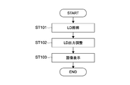
- FIG. 11 is a flowchart showing the basic operation of the control system 101.
- the control system 101 includes a laser beam L irradiation process (step 101), a laser beam L output adjustment process (step 102), and an image display process (step 103).
- the speckle contrast is evaluated based on the speckle image of the subject M photographed using the laser light L for illumination.
- the laser is adjusted.
- the output of light L is adjusted.
- the image display step the output adjustment result of the laser light L and the speckle contrast image of the subject are displayed on the display unit 40.
- FIG. 12 is a flowchart illustrating an example of a processing procedure of the control device 30.
- the control device 30 outputs a power-on command for the laser light source 11 to the laser driver 14 as the control signal S1 (step 201). Then, the drive current of the laser light L is adjusted to a set current value (for example, 300 mA), and the subject M is irradiated with the laser light L (step 202). These processes correspond to the process of step 101 in FIG.
- the control device 30 acquires a speckle image of the subject M illuminated with the laser light L via the imaging unit 20, and based on the image signal Vs, specs of the speckle image.
- Data (speckle contrast (SC) in this example) is calculated using the above-described calculation method (step 203).
- the speckle contrast is calculated based on the speckle image (standard speckle image) of the standard sample M2 (diffusion plate) among the speckle images of the subject M.
- the signal generator 32 determines whether or not the speckle contrast of the standard sample M2 is equal to or greater than a predetermined threshold (hereinafter referred to as a first threshold). Is displayed on the display unit 40 (step 208).
- the display control is executed by outputting a control signal S2 from the display control unit 33 to the display unit 40.
- the signal generation unit 32 increases or decreases the output of the laser light source 11 so that the speckle contrast is equal to or higher than the first threshold.
- S1 is generated and output to the laser driver 14 (step 205).
- the laser light source 11 can be controlled to an output that provides a high-definition observation image having a desired speckle contrast.
- the first threshold value is not particularly limited, and can be set as appropriate according to the contents of the observation object M1, and is set to, for example, 0.4 in the case of blood flow observation.
- the signal generator 32 When the speckle data is less than the first threshold, the signal generator 32 performs control to increase or decrease the output of the laser light source 11 by a predetermined amount until the speckle data becomes equal to or higher than the first threshold. Repeatedly execute (steps 203 to 206). This is because, as shown in FIGS. 8 and 10, speckle contrast may be improved by fine adjustment of the drive current value.
- the signal generation unit 32 finely adjusts the current value of the laser light source 11 to ⁇ 10 mA (290 mA) of the set current value (300 mA), and the speckle contrast of the standard speckle image at that time is greater than or equal to the first threshold value. It is determined whether or not. If the speckle contrast is equal to or higher than the first threshold, the display unit 40 displays that the adjustment of the laser output has been completed (step 208).
- the signal generation unit 32 finely adjusts the current value of the laser light source 11 to +10 mA (310 mA) of the set current value, and again, Evaluate speckle contrast. Thereafter, the signal generator 32 sets the current value of the laser light source 11 to ⁇ 20 mA (280 mA), +20 mA (320 mA), ⁇ 30 mA (270 mA) and the set current value until a speckle contrast equal to or higher than the first threshold is obtained. Sequentially change to +30 mA (330 mA).
- the adjustment range of the drive current is not limited to 10 mA, and may be set to an appropriate value such as 5 mA.
- the signal generation unit 32 when the increase or decrease in the output of the laser light source exceeds the second threshold (for example, ⁇ 30 mA), the signal generation unit 32 generates an error signal indicating an abnormality of the laser light source 11, and to that effect Is displayed on the display unit 40 (step 207). Thereby, since the presence or absence of abnormality of the laser light source 11 can be detected, it is possible to provide the user with an announcement that prompts inspection of the illumination unit 10, replacement of the laser light source 11, and the like.
- the second threshold for example, ⁇ 30 mA
- the oscillation spectrum of the laser light source 11 is controlled based on the speckle data calculated from the image signal of the subject M, the oscillation spectrum of the laser light source 11 can be controlled. Variations can be suppressed, and blood flow and the like flowing through the cerebral blood vessels can be observed with high accuracy.
- the oscillation spectrum of the laser light source 11 is calibrated using the speckle image (standard speckle image) of the standard sample M2
- the oscillation spectrum of the laser light source or its variation is highly accurate. Can be detected.
- the standard sample M2 is arranged in the same operative field (imaging region) as the observation object M1, the standard speckle image under the same illumination condition as the observation object M1 is provided. Can be obtained. Thereby, the calibration accuracy of the output of the laser light source 11 is improved.
- the calibration of the output of the laser light source 11 is performed not only before the operation but also at any timing during the operation, for example, the angle of view of the imaging unit 2. Even after adjustment, it can be carried out easily and quickly.
- the state of the laser beam can be easily grasped in real time based on the speckle contrast of the image without requiring a dedicated measuring device for measuring the spectrum width of the laser beam.
- the size and complexity of the entire system can be avoided.
- FIG. 13 is a schematic configuration diagram illustrating a control system 102 according to the second embodiment of the present technology.
- the configuration different from the first embodiment will be mainly described, and the same configuration as the first embodiment will be denoted by the same reference numeral, and the description thereof will be omitted or simplified.
- the imaging unit 20 includes a first camera 201 that captures an observation object M1 that is a subject, and a second camera 202 that captures a standard sample M2.
- the first camera 201 acquires an image (speckle image) of the observation object M1 and outputs it to the control device 30 as the first image signal Vs1.
- the second camera 202 acquires an image (standard speckle image) of the standard sample M2, and outputs it to the control device 30 as the second image signal Vs2.
- the illumination unit 10 includes a laser light source 11 that irradiates the observation object M1 with the laser light L1, and an optical fiber 15 that irradiates the standard sample M2 with the laser light L.
- the optical fiber 15 is connected to, for example, the emission end of the laser light source 11, and is constituted by a branching optical fiber that branches a part of the laser light L emitted from the laser light source 11 and irradiates the standard sample M2. Thereby, the laser beam L from the same laser light source 11 can be simultaneously irradiated onto the observation object M1 and the standard sample M2.
- the control device 30 calculates the speckle contrast based on the second image signal Vs2 output from the second camera 202, and when the value is less than the first threshold as in the first embodiment.
- a control signal S1 for controlling the output of the laser light source 11 is generated so that the speckle contrast is equal to or higher than the first threshold.
- the control device 30 generates a speckle contrast image of the observation object M1 based on the first image signal Vs1 output from the first camera 201 and displays the speckle contrast image on the display unit 40.
- a standard speckle image necessary for adjusting the output of the laser light source 11 can be obtained even when the standard sample M2 is disposed at a position relatively distant from the observation object M1.
- the illumination conditions of the laser beam L can be individually optimized for each of the observation object M1 and the standard sample M2.
- the observation object M1 and the standard sample M2 can be photographed by the separate cameras 201 and 202, the photographing conditions of the cameras 201 and 202 can be individually optimized. As a result, fine speckle images can be easily acquired for each of the observation object M1 and the standard sample M2.
- FIG. 14 is a schematic configuration diagram illustrating a control system 103 according to the third embodiment of the present technology.
- the configuration different from the first embodiment will be mainly described, and the same configuration as the first embodiment will be denoted by the same reference numeral, and the description thereof will be omitted or simplified.
- the control system 103 of this embodiment is different from that of the first embodiment in that the standard sample M2 is configured to be relatively movable with respect to the observation object M1. That is, the standard sample M2 is configured to be able to reciprocate between a retracted position indicated by a solid line in the drawing and an imaging position indicated by a two-dot chain line in the drawing.
- the retreat position is set to a position outside the imaging area of the imaging unit 20, and the imaging position is set to a position within the imaging area of the imaging unit 20, for example, a position directly above the observation object M1.
- the same effect as that of the first embodiment can be obtained.
- the standard sample M2 can be retracted to the retracted position at a time other than the adjustment process of the output of the laser light source 11, it is possible to secure a relatively wide surgical field for the observation object M1. it can.
- the standard sample M2 is held by a holding unit configured by an appropriate reciprocating mechanism such as an air cylinder or a linear motion motor, not shown.
- a holding unit configured by an appropriate reciprocating mechanism such as an air cylinder or a linear motion motor, not shown.
- the first state in which the standard sample M2 is disposed within the photographing region of the photographing unit 20 and the second state in which the standard sample M2 is disposed outside the photographing region of the photographing unit 20 are described. And can be selectively switched.
- the configuration of the holding unit is not limited to this, and may be configured by a rotation mechanism as will be described later.
- FIG. 15 is a schematic configuration diagram illustrating a control system 104 according to the fourth embodiment of the present technology.
- the configuration different from the first embodiment will be mainly described, and the same configuration as the first embodiment will be denoted by the same reference numeral, and the description thereof will be omitted or simplified.
- the control system 104 of this embodiment is different from that of the first embodiment in that the standard sample M2 is configured to be movable relative to the observation object M1.
- the control system 104 of this embodiment includes a rotary stage 60 as a holding unit that holds the standard sample M2, and a stage controller 50 that controls driving of the rotary stage 60.
- the rotation stage 60 rotates the standard sample M2 around the rotation axis 60a, so that the standard sample M2 is arranged in the imaging region of the imaging unit 20, and the standard sample M2 is captured by the imaging unit 20.
- the second state arranged outside the region is configured to be selectively switched.
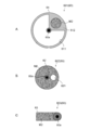
- FIG. 16A to 16C are schematic plan views showing a configuration example of the rotary stage 60.
- FIG. 16A to 16C are schematic plan views showing a configuration example of the rotary stage 60.
- a rotary stage 601 shown in FIG. 16A has a circular stage body 61 having a rotary shaft 60a at the center.
- the stage main body 61 includes an opening 611 and a holding unit 612 that holds the standard sample M2.
- the opening 611 has a fan shape, and allows the imaging of the observation object M1 by opening the imaging area of the observation object M1 by the imaging unit 20.
- the central angle of the opening 611 is not particularly limited, and may be smaller or larger than the illustrated angle (about 270 degrees), as long as the imaging region of the observation object M1 can be secured.
- the holding unit 612 is formed in a size that allows the standard sample M2 to be arranged in the imaging region at a predetermined rotational position.
- the planar shape of the standard sample M2 is not limited to the circular shape shown in the drawing, and may be any other geometric shape such as a rectangle.
- the opening 611 is formed with a larger area than the standard sample M2, but the present invention is not limited to this, and the standard sample M2 may be formed with a larger area than the opening as shown in FIG. 16B. .
- a rotary stage 602 shown in FIG. 16B has a circular stage main body 62 centered on a rotary shaft 60a and supporting the standard sample M2.
- the stage main body 62 may be composed of a standard sample M2.
- the stage main body 62 has an opening 621 that is formed in a size that can secure an imaging region of the observation object M1 by the imaging unit 20 at a predetermined rotational position.
- the opening 621 is not limited to a circle, and may be another geometric shape such as a rectangle.
- a rotary stage 603 shown in FIG. 16C has a rectangular stage body 63 that has a central axis 60a at one end and supports the standard sample M2.
- the stage main body 63 may be composed of a standard sample M2.
- the stage main body 63 is formed in an appropriate size that can be arranged in the imaging region of the imaging unit 20 at a predetermined rotational position.
- the same effect as that of the first embodiment can be obtained.
- the standard sample M2 can be retracted to the retracted position at a time other than the adjustment process of the output of the laser light source 11, it is possible to secure a relatively wide surgical field for the observation object M1. it can.
- ⁇ Fifth Embodiment> 17 and 18 are schematic configuration diagrams illustrating a control system 105 according to the fifth embodiment of the present technology.
- the configuration different from the first embodiment will be mainly described, and the same configuration as the first embodiment will be denoted by the same reference numeral, and the description thereof will be omitted or simplified.
- control system 105 is applied to a microscope for brain surgery, and a general-purpose surgical drape (cloth) capable of obtaining a standard speckle image is used as the standard sample M2.
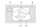
- the illumination unit 10 irradiates the patient's head with the laser beam L, and the imaging unit 20 displays an image (speckle image) of the patient's head (observation object M1) and the surrounding drape (standard sample M2). Get at the same time.
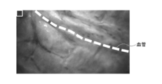
- An example of the image is schematically shown in FIG.
- M11 represents a blood vessel and M12 represents a dura mater.
- the control device 30 calculates the speckle contrast of the image from the speckle image of the drape (M2).
- a region R1 indicated by a broken line in FIG. 19 is a pixel indication region for calculating a speckle contrast value.
- the region R1 may be arbitrarily selected by the control device 30, or may be selected by a user operation.
- the control device 30 holds the speckle contrast value obtained at an arbitrary timing (for example, when the illumination unit 10 is turned on at the start or when the user instructs the speckle contrast calculation region R1).
- the obtained speckle image and the speckle contrast value are compared and there is a divergence of a predetermined value or more (for example, the difference in speckle contrast is 0.1). It is possible to display an error.
- the speckle contrast may be lowered. Therefore, at the start, a diffusion plate is used, and during the operation, the fluctuation of the speckle contrast value at an arbitrary setting location is confirmed. You may do it.
- the laser beam output is calibrated based on the speckle contrast generated using the speckle image (standard speckle image) of the standard sample M2, but instead, the standard sample is calibrated.
- the laser beam output may be calibrated without using M2.
- the output of the laser beam may be calibrated using a speckle image of the observation object M1.
- a region where the speckle contrast value is constant in the observation object M1 may be set as the representative value.
- speckle contrast is calculated as speckle data, but the present invention is not limited to this.
- the speckle data may be generated based on the difference between the maximum luminance and the minimum luminance of the pixel signal in the unit cell. Specifically, for a unit cell (for example, a 5 ⁇ 5 pixel column) constituting a speckle image, a value ((Gmax ⁇ Gmin) / (I)) obtained by dividing the difference between the minimum luminance and the maximum luminance by an average value is obtained. It may be used.
- a control signal for adjusting the output of the laser light source may be generated based on speckle data generated by such a calculation method.
- the speckle contrast of the standard sample M2 is evaluated when the output of the laser light source 11 is calibrated.
- the present technology can be used for temperature management of the laser light source 11.
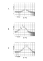
- FIGS. 20A to 20C show an example in which the spectrum width of the LD varies depending on the temperature.
- A indicates the spectral width when 25 [° C.]
- B indicates 23 [° C.]
- C indicates 27 [° C.].
- the speckle contrast obtained by irradiating the standard sample with the laser light also varies in each state.
- the state shown in A has a smaller spectral width than the states shown in B and C, so that the highest speckle contrast can be obtained.
- control device 30 It is possible to cause the control device 30 to execute the following process by utilizing the phenomenon that the spectrum width of the LD varies depending on the temperature. That is, as a normal flow, while adjusting the LD temperature, the current value of the LD is adjusted (output), the state of the LD is confirmed by calculating the speckle contrast, and the process proceeds to speckle image acquisition. For example, 60 images (in the case of 60 [Hz]) are always acquired per second, and speckle contrast calculation is performed. When a speckle contrast image is always observed, when it is normal, the temperature adjustment of the LD is always maintained at a certain temperature, for example, 25 [° C.] by a Peltier element or the like.
- the control device 30 When the temperature of the LD cannot be adjusted due to the failure of the Peltier element, or when the fan that releases heat breaks down and the control of the Peltier element becomes ineffective, this phenomenon appears as a decrease in speckle contrast. Therefore, when detecting such a decrease in contrast, the control device 30 performs an error display on the display unit 40 or executes a process of reducing the output of the illumination unit 10. Thereby, it becomes possible to prevent the LD from being heated and broken more than necessary.
- control system can be configured as an endoscope or a microscope.
- examples of the observation target include biological tissues such as biological cells, tissues, and organs.
- biological tissues such as biological cells, tissues, and organs.
- a control method and a program according to the present technology are executed by linking a computer operated by a user or the like with another computer that can communicate via a network or the like, and a control system according to the present technology is constructed. May be.
- control method and the program according to the present technology can be executed not only in a computer system configured by a single computer but also in a computer system in which a plurality of computers operate in conjunction with each other.
- the system means a set of a plurality of components (devices, modules (parts), etc.), and it does not matter whether all the components are in the same housing. Accordingly, a plurality of devices housed in separate housings and connected via a network and a single device housing a plurality of modules in one housing are all systems.
- Execution of the control method and the program according to the present technology by the computer system is different when, for example, generation of speckle data, generation of a control signal for controlling the output of the laser light source is executed by a single computer, and each process is different Including both when executed by a computer.
- the execution of each process by a predetermined computer includes causing another computer to execute a part or all of the process and acquiring the result.
- control method and program according to the present technology can also be applied to a configuration of cloud computing in which one function is shared by a plurality of devices via a network and is jointly processed.
- the speckle image obtained by irradiating the standard sample with the laser is acquired by the image sensor (imaging unit 20), but instead, a line sensor, a photo detector (PD), or the like is used. You may make it acquire the said speckle image using another optical element.
- control device 30 and the laser driver 14 are configured as separate devices, but may be configured as a common device.
- control device 30 and the imaging unit 20, or the control device 30 and the display unit 40 may also be configured by a common device.
- the brain and cerebral blood vessels have been described as examples of the observation object M1, but the present invention is not limited thereto, and other organs other than the brain such as the heart or the blood vessels or lymph glands of the scattering substance may be used.
- the present technology can be applied to any living tissue having a site with flow.
- the present technology may be applied to the evaluation of inspection devices using microchannels. For example, it becomes possible to detect the flow rate of the solvent flowing in the flow path with high accuracy.
- the fields to which the present technology can be applied are not limited.
- this technique can also take the following structures.
- Speckle data is generated based on an image signal of a subject photographed using laser light for illumination, and an output of a laser light source that irradiates the laser light is controlled based on the generated speckle data.
- a control device comprising a signal generation unit for generating a control signal.
- the subject includes an observation object and a standard sample for calibration, The signal generation unit generates the speckle data based on an image signal of the standard sample.
- the control device When the speckle data is less than a first threshold, the signal generator generates a control signal for increasing or decreasing the output of the laser light source so that the speckle data is equal to or greater than the first threshold. Generate control unit.
- the signal generation unit When the speckle data is less than the first threshold, the signal generation unit increases or decreases the output of the laser light source by a predetermined amount until the speckle data becomes equal to or higher than the first threshold.
- the control device includes speckle contrast
- the signal generation unit generates the control signal based on the speckle contrast.
- the control device has a plurality of pixel signals each including luminance information
- the speckle data includes a difference between maximum brightness and minimum brightness
- the signal generation unit generates the control signal based on a difference between the minimum luminance and the maximum luminance.
- An illumination unit having a laser light source for irradiating the observation target with laser light, and a laser driver for adjusting the output of the laser light source, A standard sample for calibration that can be arranged at a position to receive the irradiation of the laser beam;
- An imaging unit that acquires images of the observation object and the standard sample that have been irradiated with the laser beam;
- a control device having a signal generation unit that generates speckle data from individual pixel signals constituting the image of the standard sample and generates a control signal for controlling the laser driver based on the generated speckle data; Control system provided.
- the control device further includes a display control unit that displays a speckle contrast image of the observation object on the display unit.
- the control system according to (8) or (9), The standard sample is a light diffusing optical element.
- the control system according to (10), The standard sample is a diffusion plate.
- the control system according to (10), The standard sample is a surgical drape control system.
Landscapes
- Health & Medical Sciences (AREA)
- Life Sciences & Earth Sciences (AREA)
- Physics & Mathematics (AREA)
- General Health & Medical Sciences (AREA)
- Surgery (AREA)
- Engineering & Computer Science (AREA)
- Biomedical Technology (AREA)
- Heart & Thoracic Surgery (AREA)
- Medical Informatics (AREA)
- Molecular Biology (AREA)
- Pathology (AREA)
- Animal Behavior & Ethology (AREA)
- Biophysics (AREA)
- Public Health (AREA)
- Veterinary Medicine (AREA)
- Analytical Chemistry (AREA)
- Chemical & Material Sciences (AREA)
- Optics & Photonics (AREA)
- General Physics & Mathematics (AREA)
- Radiology & Medical Imaging (AREA)
- Neurology (AREA)
- Nuclear Medicine, Radiotherapy & Molecular Imaging (AREA)
- Physiology (AREA)
- Hematology (AREA)
- Cardiology (AREA)
- General Engineering & Computer Science (AREA)
- Computer Vision & Pattern Recognition (AREA)
- Ophthalmology & Optometry (AREA)
- Neurosurgery (AREA)
- Psychology (AREA)
- Investigating Or Analysing Materials By Optical Means (AREA)
- Microscoopes, Condenser (AREA)
- Measuring Pulse, Heart Rate, Blood Pressure Or Blood Flow (AREA)
Abstract
Le dispositif de commande selon un mode de réalisation de la présente invention comprend une unité de génération de signal. L'unité de génération de signal génère des données de tavelure sur la base d'un signal d'image d'un sujet photographié à l'aide d'une lumière laser pour l'éclairage, et génère un signal de commande pour commander la sortie de la lumière laser sur la base des données de tavelure ainsi générées.
Priority Applications (2)
| Application Number | Priority Date | Filing Date | Title |
|---|---|---|---|
| JP2019517479A JPWO2018207471A1 (ja) | 2017-05-09 | 2018-03-20 | 制御装置、制御システム、制御方法、及びプログラム |
| US16/609,799 US20200060557A1 (en) | 2017-05-09 | 2018-03-20 | Control apparatus, control system, control method, and program |
Applications Claiming Priority (2)
| Application Number | Priority Date | Filing Date | Title |
|---|---|---|---|
| JP2017-093013 | 2017-05-09 | ||
| JP2017093013 | 2017-05-09 |
Publications (1)
| Publication Number | Publication Date |
|---|---|
| WO2018207471A1 true WO2018207471A1 (fr) | 2018-11-15 |
Family
ID=64105456
Family Applications (1)
| Application Number | Title | Priority Date | Filing Date |
|---|---|---|---|
| PCT/JP2018/010984 Ceased WO2018207471A1 (fr) | 2017-05-09 | 2018-03-20 | Dispositif de commande, système de commande, procédé de commande et programme |
Country Status (3)
| Country | Link |
|---|---|
| US (1) | US20200060557A1 (fr) |
| JP (1) | JPWO2018207471A1 (fr) |
| WO (1) | WO2018207471A1 (fr) |
Cited By (4)
| Publication number | Priority date | Publication date | Assignee | Title |
|---|---|---|---|---|
| JP2020159814A (ja) * | 2019-03-26 | 2020-10-01 | 東芝テック株式会社 | 検出装置 |
| JP2021016483A (ja) * | 2019-07-18 | 2021-02-15 | ソフトケア有限会社 | スペックル信号調整装置、並びにこれを使用した画像化測定装置の校正方法および画像化測定装置の異常診断方法 |
| WO2022202051A1 (fr) * | 2021-03-22 | 2022-09-29 | ソニーグループ株式会社 | Système d'observation biologique, procédé d'observation biologique et dispositif d'irradiation |
| JP2023524029A (ja) * | 2020-04-30 | 2023-06-08 | シーメンス・ヘルスケア・ダイアグノスティックス・インコーポレイテッド | 装置、装置を較正する方法、および装置を較正するためのデバイス |
Families Citing this family (2)
| Publication number | Priority date | Publication date | Assignee | Title |
|---|---|---|---|---|
| US20200037896A1 (en) * | 2018-08-03 | 2020-02-06 | Guillermo Aguilar-Mendoza | Optical flow analysis method and detection device |
| CN116628955B (zh) * | 2023-05-08 | 2025-08-22 | 中国西安卫星测控中心 | 一种基于约翰逊准则的激光干扰效果仿真评估方法 |
Citations (7)
| Publication number | Priority date | Publication date | Assignee | Title |
|---|---|---|---|---|
| JPH1142242A (ja) * | 1997-03-07 | 1999-02-16 | Kaltenbach & Voigt Gmbh & Co | 歯の検査方法並びに装置 |
| JP2010532699A (ja) * | 2007-07-06 | 2010-10-14 | インダストリアル リサーチ リミテッド | レーザスペックル画像化システム及び方法 |
| JP2010243280A (ja) * | 2009-04-03 | 2010-10-28 | Topcon Corp | 光画像計測装置 |
| US20120162438A1 (en) * | 2009-09-04 | 2012-06-28 | The John Hopkins University | Multimodal laser speckle imaging |
| JP2012127937A (ja) * | 2010-11-26 | 2012-07-05 | Ricoh Co Ltd | 光学センサ及び画像形成装置 |
| US20120188354A1 (en) * | 2011-01-24 | 2012-07-26 | Elizabeth Alice Munro | System and method for optical imaging with vertical cavity surface emitting lasers |
| JP2016151524A (ja) * | 2015-02-18 | 2016-08-22 | ソニー株式会社 | スペックルイメージング装置、スペックルイメージングシステム及びスペックルイメージング方法 |
-
2018
- 2018-03-20 US US16/609,799 patent/US20200060557A1/en not_active Abandoned
- 2018-03-20 WO PCT/JP2018/010984 patent/WO2018207471A1/fr not_active Ceased
- 2018-03-20 JP JP2019517479A patent/JPWO2018207471A1/ja active Pending
Patent Citations (7)
| Publication number | Priority date | Publication date | Assignee | Title |
|---|---|---|---|---|
| JPH1142242A (ja) * | 1997-03-07 | 1999-02-16 | Kaltenbach & Voigt Gmbh & Co | 歯の検査方法並びに装置 |
| JP2010532699A (ja) * | 2007-07-06 | 2010-10-14 | インダストリアル リサーチ リミテッド | レーザスペックル画像化システム及び方法 |
| JP2010243280A (ja) * | 2009-04-03 | 2010-10-28 | Topcon Corp | 光画像計測装置 |
| US20120162438A1 (en) * | 2009-09-04 | 2012-06-28 | The John Hopkins University | Multimodal laser speckle imaging |
| JP2012127937A (ja) * | 2010-11-26 | 2012-07-05 | Ricoh Co Ltd | 光学センサ及び画像形成装置 |
| US20120188354A1 (en) * | 2011-01-24 | 2012-07-26 | Elizabeth Alice Munro | System and method for optical imaging with vertical cavity surface emitting lasers |
| JP2016151524A (ja) * | 2015-02-18 | 2016-08-22 | ソニー株式会社 | スペックルイメージング装置、スペックルイメージングシステム及びスペックルイメージング方法 |
Cited By (8)
| Publication number | Priority date | Publication date | Assignee | Title |
|---|---|---|---|---|
| JP2020159814A (ja) * | 2019-03-26 | 2020-10-01 | 東芝テック株式会社 | 検出装置 |
| JP7229828B2 (ja) | 2019-03-26 | 2023-02-28 | 東芝テック株式会社 | 検出装置 |
| JP2021016483A (ja) * | 2019-07-18 | 2021-02-15 | ソフトケア有限会社 | スペックル信号調整装置、並びにこれを使用した画像化測定装置の校正方法および画像化測定装置の異常診断方法 |
| JP7266293B2 (ja) | 2019-07-18 | 2023-04-28 | ソフトケア有限会社 | スペックル信号調整装置、並びにこれを使用した画像化測定装置の校正方法および画像化測定装置の異常診断方法 |
| JP2023524029A (ja) * | 2020-04-30 | 2023-06-08 | シーメンス・ヘルスケア・ダイアグノスティックス・インコーポレイテッド | 装置、装置を較正する方法、および装置を較正するためのデバイス |
| JP7438403B2 (ja) | 2020-04-30 | 2024-02-26 | シーメンス・ヘルスケア・ダイアグノスティックス・インコーポレイテッド | 装置、装置を較正する方法、および装置を較正するためのデバイス |
| US12022584B2 (en) | 2020-04-30 | 2024-06-25 | Siemens Healthcare Diagnostics Inc. | Apparatus, method for calibrating an apparatus and device therefor |
| WO2022202051A1 (fr) * | 2021-03-22 | 2022-09-29 | ソニーグループ株式会社 | Système d'observation biologique, procédé d'observation biologique et dispositif d'irradiation |
Also Published As
| Publication number | Publication date |
|---|---|
| JPWO2018207471A1 (ja) | 2020-05-14 |
| US20200060557A1 (en) | 2020-02-27 |
Similar Documents
| Publication | Publication Date | Title |
|---|---|---|
| JPWO2018207471A1 (ja) | 制御装置、制御システム、制御方法、及びプログラム | |
| US8100531B2 (en) | Ophthalmoscope including an electronic shutter | |
| CN101926640B (zh) | 活体人眼视网膜动态成像仪 | |
| JP2010133969A5 (fr) | ||
| WO2020013325A1 (fr) | Dispositif de génération d'images et procédé de génération d'images | |
| US20220133140A1 (en) | Light source apparatus, medical observation system, adjustment apparatus, illumination method, adjustment method, and program | |
| JP2008295971A (ja) | 眼底カメラ | |
| CN108670172A (zh) | 基于测光反馈的荧光导航系统及其术中荧光导航调整方法 | |
| JP2013252185A (ja) | 内視鏡及び内視鏡装置 | |
| WO2017163542A1 (fr) | Dispositif d'analyse d'image et procédé d'analyse d'image | |
| US20200015677A1 (en) | Ophthalmic imaging apparatuses and method for the same | |
| CN106264476B (zh) | 舌象检测设备 | |
| US20150257640A1 (en) | Eye image and video capture system and associated methods | |
| US10433721B2 (en) | Ophthalmic apparatus and control method for the same | |
| CN116171126A (zh) | 用于设定和控制眼科设备的照明场的参数的方法和设备 | |
| CN107767347A (zh) | 一种电子内窥镜图像增强方法、装置及系统 | |
| KR101959394B1 (ko) | 다중-노출 레이저 스펙클 영상 수집 장치 | |
| JP5008540B2 (ja) | 眼科機器 | |
| JP2014200621A (ja) | 眼科用観察装置及びその使用方法 | |
| JP6535701B2 (ja) | 撮像装置 | |
| JPWO2018198908A1 (ja) | 毛髪観察方法、位相差顕微鏡システム及びプレパラート | |
| JP2012120764A (ja) | 内視鏡システム、光学装置、および波長可変素子の透過光の波長帯域のずれ補正方法 | |
| US20170340203A1 (en) | Imaging apparatus and control method for the same | |
| US20240382096A1 (en) | Medical information processing apparatus, medical observation system, and medical information processing method | |
| US20250254405A1 (en) | Endoscope having simultaneous multi-modal imaging |
Legal Events
| Date | Code | Title | Description |
|---|---|---|---|
| 121 | Ep: the epo has been informed by wipo that ep was designated in this application |
Ref document number: 18799312 Country of ref document: EP Kind code of ref document: A1 |
|
| ENP | Entry into the national phase |
Ref document number: 2019517479 Country of ref document: JP Kind code of ref document: A |
|
| NENP | Non-entry into the national phase |
Ref country code: DE |
|
| 122 | Ep: pct application non-entry in european phase |
Ref document number: 18799312 Country of ref document: EP Kind code of ref document: A1 |