WO2018212360A1 - 車両 - Google Patents
車両 Download PDFInfo
- Publication number
- WO2018212360A1 WO2018212360A1 PCT/JP2018/019500 JP2018019500W WO2018212360A1 WO 2018212360 A1 WO2018212360 A1 WO 2018212360A1 JP 2018019500 W JP2018019500 W JP 2018019500W WO 2018212360 A1 WO2018212360 A1 WO 2018212360A1
- Authority
- WO
- WIPO (PCT)
- Prior art keywords
- steering
- vehicle
- vehicle body
- damper
- torque
- Prior art date
- Legal status (The legal status is an assumption and is not a legal conclusion. Google has not performed a legal analysis and makes no representation as to the accuracy of the status listed.)
- Ceased
Links
Images









Classifications
-
- B—PERFORMING OPERATIONS; TRANSPORTING
- B62—LAND VEHICLES FOR TRAVELLING OTHERWISE THAN ON RAILS
- B62D—MOTOR VEHICLES; TRAILERS
- B62D5/00—Power-assisted or power-driven steering
- B62D5/06—Power-assisted or power-driven steering fluid, i.e. using a pressurised fluid for most or all the force required for steering a vehicle
-
- B—PERFORMING OPERATIONS; TRANSPORTING
- B62—LAND VEHICLES FOR TRAVELLING OTHERWISE THAN ON RAILS
- B62K—CYCLES; CYCLE FRAMES; CYCLE STEERING DEVICES; RIDER-OPERATED TERMINAL CONTROLS SPECIALLY ADAPTED FOR CYCLES; CYCLE AXLE SUSPENSIONS; CYCLE SIDECARS, FORECARS, OR THE LIKE
- B62K5/00—Cycles with handlebars, equipped with three or more main road wheels
- B62K5/02—Tricycles
- B62K5/027—Motorcycles with three wheels
-
- B—PERFORMING OPERATIONS; TRANSPORTING
- B60—VEHICLES IN GENERAL
- B60G—VEHICLE SUSPENSION ARRANGEMENTS
- B60G21/00—Interconnection systems for two or more resiliently-suspended wheels, e.g. for stabilising a vehicle body with respect to acceleration, deceleration or centrifugal forces
- B60G21/02—Interconnection systems for two or more resiliently-suspended wheels, e.g. for stabilising a vehicle body with respect to acceleration, deceleration or centrifugal forces permanently interconnected
- B60G21/04—Interconnection systems for two or more resiliently-suspended wheels, e.g. for stabilising a vehicle body with respect to acceleration, deceleration or centrifugal forces permanently interconnected mechanically
- B60G21/05—Interconnection systems for two or more resiliently-suspended wheels, e.g. for stabilising a vehicle body with respect to acceleration, deceleration or centrifugal forces permanently interconnected mechanically between wheels on the same axle but on different sides of the vehicle, i.e. the left and right wheel suspensions being interconnected
-
- B—PERFORMING OPERATIONS; TRANSPORTING
- B60—VEHICLES IN GENERAL
- B60G—VEHICLE SUSPENSION ARRANGEMENTS
- B60G3/00—Resilient suspensions for a single wheel
- B60G3/18—Resilient suspensions for a single wheel with two or more pivoted arms, e.g. parallelogram
- B60G3/20—Resilient suspensions for a single wheel with two or more pivoted arms, e.g. parallelogram all arms being rigid
-
- B—PERFORMING OPERATIONS; TRANSPORTING
- B62—LAND VEHICLES FOR TRAVELLING OTHERWISE THAN ON RAILS
- B62D—MOTOR VEHICLES; TRAILERS
- B62D1/00—Steering controls, i.e. means for initiating a change of direction of the vehicle
- B62D1/02—Steering controls, i.e. means for initiating a change of direction of the vehicle vehicle-mounted
- B62D1/04—Hand wheels
-
- B—PERFORMING OPERATIONS; TRANSPORTING
- B62—LAND VEHICLES FOR TRAVELLING OTHERWISE THAN ON RAILS
- B62D—MOTOR VEHICLES; TRAILERS
- B62D7/00—Steering linkage; Stub axles or their mountings
- B62D7/16—Arrangement of linkage connections
-
- B—PERFORMING OPERATIONS; TRANSPORTING
- B62—LAND VEHICLES FOR TRAVELLING OTHERWISE THAN ON RAILS
- B62K—CYCLES; CYCLE FRAMES; CYCLE STEERING DEVICES; RIDER-OPERATED TERMINAL CONTROLS SPECIALLY ADAPTED FOR CYCLES; CYCLE AXLE SUSPENSIONS; CYCLE SIDECARS, FORECARS, OR THE LIKE
- B62K5/00—Cycles with handlebars, equipped with three or more main road wheels
- B62K5/02—Tricycles
- B62K5/05—Tricycles characterised by a single rear wheel
-
- B—PERFORMING OPERATIONS; TRANSPORTING
- B62—LAND VEHICLES FOR TRAVELLING OTHERWISE THAN ON RAILS
- B62K—CYCLES; CYCLE FRAMES; CYCLE STEERING DEVICES; RIDER-OPERATED TERMINAL CONTROLS SPECIALLY ADAPTED FOR CYCLES; CYCLE AXLE SUSPENSIONS; CYCLE SIDECARS, FORECARS, OR THE LIKE
- B62K5/00—Cycles with handlebars, equipped with three or more main road wheels
- B62K5/08—Cycles with handlebars, equipped with three or more main road wheels with steering devices acting on two or more wheels
-
- B—PERFORMING OPERATIONS; TRANSPORTING
- B62—LAND VEHICLES FOR TRAVELLING OTHERWISE THAN ON RAILS
- B62K—CYCLES; CYCLE FRAMES; CYCLE STEERING DEVICES; RIDER-OPERATED TERMINAL CONTROLS SPECIALLY ADAPTED FOR CYCLES; CYCLE AXLE SUSPENSIONS; CYCLE SIDECARS, FORECARS, OR THE LIKE
- B62K5/00—Cycles with handlebars, equipped with three or more main road wheels
- B62K5/10—Cycles with handlebars, equipped with three or more main road wheels with means for inwardly inclining the vehicle body on bends
-
- G—PHYSICS
- G01—MEASURING; TESTING
- G01C—MEASURING DISTANCES, LEVELS OR BEARINGS; SURVEYING; NAVIGATION; GYROSCOPIC INSTRUMENTS; PHOTOGRAMMETRY OR VIDEOGRAMMETRY
- G01C9/00—Measuring inclination, e.g. by clinometers, by levels
- G01C9/02—Details
-
- G—PHYSICS
- G01—MEASURING; TESTING
- G01P—MEASURING LINEAR OR ANGULAR SPEED, ACCELERATION, DECELERATION, OR SHOCK; INDICATING PRESENCE, ABSENCE, OR DIRECTION, OF MOVEMENT
- G01P15/00—Measuring acceleration; Measuring deceleration; Measuring shock, i.e. sudden change of acceleration
- G01P15/14—Measuring acceleration; Measuring deceleration; Measuring shock, i.e. sudden change of acceleration by making use of gyroscopes
-
- G—PHYSICS
- G01—MEASURING; TESTING
- G01P—MEASURING LINEAR OR ANGULAR SPEED, ACCELERATION, DECELERATION, OR SHOCK; INDICATING PRESENCE, ABSENCE, OR DIRECTION, OF MOVEMENT
- G01P15/00—Measuring acceleration; Measuring deceleration; Measuring shock, i.e. sudden change of acceleration
- G01P15/16—Measuring acceleration; Measuring deceleration; Measuring shock, i.e. sudden change of acceleration by evaluating the time-derivative of a measured speed signal
- G01P15/165—Measuring acceleration; Measuring deceleration; Measuring shock, i.e. sudden change of acceleration by evaluating the time-derivative of a measured speed signal for measuring angular accelerations
-
- G—PHYSICS
- G01—MEASURING; TESTING
- G01P—MEASURING LINEAR OR ANGULAR SPEED, ACCELERATION, DECELERATION, OR SHOCK; INDICATING PRESENCE, ABSENCE, OR DIRECTION, OF MOVEMENT
- G01P3/00—Measuring linear or angular speed; Measuring differences of linear or angular speeds
- G01P3/42—Devices characterised by the use of electric or magnetic means
- G01P3/44—Devices characterised by the use of electric or magnetic means for measuring angular speed
-
- B—PERFORMING OPERATIONS; TRANSPORTING
- B60—VEHICLES IN GENERAL
- B60G—VEHICLE SUSPENSION ARRANGEMENTS
- B60G2300/00—Indexing codes relating to the type of vehicle
- B60G2300/45—Rolling frame vehicles
-
- B—PERFORMING OPERATIONS; TRANSPORTING
- B62—LAND VEHICLES FOR TRAVELLING OTHERWISE THAN ON RAILS
- B62D—MOTOR VEHICLES; TRAILERS
- B62D1/00—Steering controls, i.e. means for initiating a change of direction of the vehicle
- B62D1/02—Steering controls, i.e. means for initiating a change of direction of the vehicle vehicle-mounted
-
- B—PERFORMING OPERATIONS; TRANSPORTING
- B62—LAND VEHICLES FOR TRAVELLING OTHERWISE THAN ON RAILS
- B62D—MOTOR VEHICLES; TRAILERS
- B62D9/00—Steering deflectable wheels not otherwise provided for
- B62D9/02—Steering deflectable wheels not otherwise provided for combined with means for inwardly inclining vehicle body on bends
Definitions
- the present invention relates to a vehicle including a vehicle body provided with two or more wheels including steering wheels.
- Patent Document 1 Japanese Patent Publication No. 2014-524864 discloses that the vehicle 100 turns. In doing so, a three-wheeled vehicle 100 is disclosed having a front wheel 106 that is inclined at approximately the same angle as the chassis 102. Special table 2014-524864
- a vehicle according to the present invention includes a vehicle body provided with two or more wheels including steering wheels for steering, and an inclination angle detection for detecting an inclination angle of the vehicle body around a roll axis. And a torque applying unit that applies a steering torque to the steered wheel in accordance with an inclination angular velocity or an inclination angular acceleration of the vehicle body obtained from the inclination angle.
- the vehicle according to the present invention is characterized in that the torque applying unit adjusts a steering angle direction and / or a steering operation speed of the steered wheel according to an inclination angular velocity of the vehicle body.
- the vehicle according to the present invention is characterized in that the torque applying section applies a steering torque in the same direction as the direction of the inclination angular velocity of the vehicle body.
- the torque application unit applies a steering torque in the same direction as the direction of the inclination angular velocity when the inclination angular velocity of the vehicle body is slower than a predetermined value, and the inclination angular velocity of the vehicle body is When it is equal to or greater than a predetermined value, a steering torque is applied in a direction opposite to the direction of the inclination angular velocity.
- the vehicle according to the present invention is characterized in that an elastic member that expands and contracts in accordance with the inclination of the vehicle body is used for the torque applying portion.
- the inclination angle detection unit is a first expansion / contraction member that expands / contracts according to the inclination angle of the vehicle body, and the torque application unit interlocks with the first expansion / contraction member, It has the 2nd expansion-contraction member which provides a steering torque with respect to the said steering wheel, It is characterized by the above-mentioned.
- the vehicle according to the present invention is characterized in that the first elastic member and the second elastic member are the same member.
- the vehicle according to the present invention includes a pair of suspension rods that house a pair of suspension arms that suspend the pair of steering wheels, a pair of horizontal links that form parallel links with the pair of suspension rods, A tie rod for aligning a steering angle, and the torque applying unit includes a damper having one end connected to the vehicle body via the tie rod and a damper link and the other end connected to the vehicle body. To do.
- the vehicle according to the present invention includes a pair of suspension rods that house a pair of suspension arms that suspend the pair of steering wheels, a pair of horizontal links that form parallel links with the pair of suspension rods, and a pair of the steering wheels.
- the vehicle according to the present invention is characterized in that a characteristic of resistance generated according to a moving speed of the piston of the first damper is different from a characteristic of resistance generated according to the moving speed of the piston of the second damper.
- the vehicle according to the present invention is characterized in that an input member for inputting a turning direction and a steering member for steering the steering wheel are mechanically connected in a semi-connected state.
- the vehicle according to the present invention is characterized in that the input member for inputting the turning direction and the steering member for steering the steering wheel are mechanically completely separated.
- the vehicle according to the present invention includes a control unit that issues a control command to the torque applying unit, and the control unit controls a steering angle direction and / or a steering operation of the steered wheel according to a tilt angular velocity of the vehicle body.
- a control command is issued to the torque applying unit so as to adjust the speed.
- the torque applying unit when the actual inclination angle is away from the target inclination angle, the torque applying unit performs the adjustment, and the actual inclination angle is approaching the target inclination angle. Is characterized in that the adjustment is not performed or weakened.
- the vehicle according to the present invention includes a torque applying unit that applies a steering torque to the steered wheels in accordance with the tilt angular velocity or the tilt angular acceleration of the vehicle body. According to such a vehicle according to the present invention.
- the problem is that the wheel is delayed following the lean of the car body and the response of turning is deteriorated, and the inertial force according to the angular velocity of the car body tilt angle acts on the driver, hindering the driving operation. It becomes possible to solve one or both of the problems of becoming.
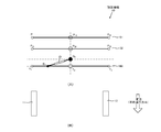
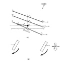
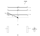
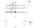
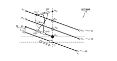
- FIG. 1 is a diagram showing an outline of a vehicle 1 according to an embodiment of the present invention. It is a figure which extracts and shows the turning mechanism 10 of the vehicle 1 which concerns on embodiment of this invention. It is a figure showing typically turning mechanism 10 of vehicles 1 concerning a 1st embodiment of the present invention. It is a figure showing typically turning mechanism 10 of vehicles 1 concerning a 1st embodiment of the present invention. It is a figure showing typically turning mechanism 10 of vehicles 1 concerning a 1st embodiment of the present invention. It is a figure showing typically turning mechanism 10 of vehicles 1 concerning a 1st embodiment of the present invention. It is a figure which shows typically the turning mechanism 10 of the vehicle 1 which concerns on 2nd Embodiment of this invention. It is a figure which shows typically the turning mechanism 10 of the vehicle 1 which concerns on 2nd Embodiment of this invention.
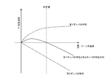
- FIG. 5 is a diagram for explaining a characteristic formed by a sum of a characteristic of a first damper 110 and a characteristic of a second damper 120. It is a figure which shows typically the turning mechanism 10 of the vehicle 1 which concerns on 7th Embodiment of this invention.
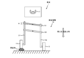
- FIG. 2 is a diagram illustrating a problem related to a vehicle 1.
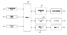
- FIG. It is a figure which shows the block structure which implement
- FIG. 1 is a diagram showing an outline of a vehicle 1 according to an embodiment of the present invention.
- the vehicle 1 is rotationally driven by two front wheels (a right front wheel 11 and a left front wheel 12) having both a lean mechanism for leaning (inclining) the vehicle body 3 and a steering mechanism, and a motor.
- the vehicle 1 according to the present invention is not limited to this, and the concept of the present invention is a vehicle provided with two or more wheels. It is possible to apply to.
- a control unit (not shown) of the vehicle 1 controls the lean operation, or the driver itself performs the lean operation of the vehicle 1, and the vehicle 1 assists this.
- the lean operation of the vehicle 1 includes all lean mechanisms such as those performed only by the driver himself.
- the case where the wheel having the lean mechanism and the wheels to which the steering torque is applied are the front right wheel 11 and the left front wheel 12 are described. Even in the case where the front wheel and the wheel having the lean mechanism are rear wheels, or the wheel to which the steering torque is applied is the rear wheel and the wheel having the lean mechanism is the front wheel. It is included in the category.
- An input member for inputting the turning direction of the vehicle 1 to the vehicle 1 (for example, a handle, a joystick, etc.) and a steering member for two front wheels (right front wheel 11 and left front wheel 12) as steering wheels.
- the input member and the steering member of the two front wheels (the right front wheel 11 and the left front wheel 12) that are the steering wheels are mechanically loosely connected (for example: Both of which are connected by a spring or the like).
- An example of the input member is an input shaft such as a handle shaft that is rotated by a driver's operation in order to turn the vehicle.
- An example of a steering member is a steering shaft that rotates as the steering wheel steers.
- the input member and the steering member are mechanically loosely connected means that the input member and the steering member are fastening forces that allow the steering angle of the steered wheels to follow the turning direction due to the inclination of the vehicle body. And it says that it is connected with the fastening force of the grade which enables torque transmission with respect to an input member from a steering member.
- mechanically loosely connected is mechanically connected in a semi-connected state.
- the two front wheels (the right front wheel 11 and the left front wheel 12) of the vehicle 1 are provided with predetermined trails, and the steering mechanism of the front wheels (the right front wheel 11 and the left front wheel 12) is accompanied by the lean operation of the vehicle body 3. Even when it does not function, it is configured to be able to turn following the lean operation of the vehicle body 3.
- the vehicle body 3 in the vehicle 1 is provided with a seat 5 on which a driver can sit when boarding.
- the driver sits on the seat 5, operates a device (not shown) for inputting a turning direction, It is assumed that an input device (not shown) is operated.
- a lean mechanism that leans the vehicle body 3 with a height difference between the right front wheel 11 and the left front wheel 12, and a steering mechanism that steers the right front wheel 11 and the left front wheel 12 itself.
- a turning mechanism 10 having a mechanism is also provided.
- the turning mechanism 10 is configured to perform the lean operation and the steering operation of the two wheels.
- the turning mechanism 10 performs the lean operation and the steering operation of only one wheel. It can also be configured.
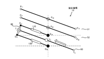
- the turning mechanism 10 includes a right suspension arm 31 and a left suspension arm 32 that respectively suspend the right front wheel 11 and the left front wheel 12.
- the right front wheel 11 is attached to the right suspension arm 31 via the right front wheel axle 41
- the left front wheel 12 is attached to the left suspension arm 32 via the left front wheel axle 42.
- the left front wheel 12 rotates with respect to the right suspension arm 31 and the left suspension arm 32 so that the vehicle 1 can travel.
- the right front wheel 11 and the left front wheel 12 are rotatable with respect to the right suspension arm 31 and the left suspension arm 32, thereby giving a predetermined steering angle to the right front wheel 11 and the left front wheel 12. Be able to.
- the right suspension arm 31 and the left suspension arm 32 are accommodated in the right suspension rod 21 and the left suspension rod 22 so as to be suspended from the right suspension rod 21 and the left suspension rod 22, respectively.
- the right suspension rod 21 and the left suspension rod 22 form a parallel link with the first horizontal link 51 and the second horizontal link 52 that extend in the horizontal direction.
- the center of rotation of the parallel link is indicated as P 11 , P 12 , P 21 , P 22 as shown in the figure.
- a central tube 25 fixed to the vehicle body 3 is provided between the right suspension rod 21 and the left suspension rod 22.
- the first horizontal link 51 is rotatable at P 10 with respect to the central tube 25, and the second horizontal link 52 is rotatable at P 20 with respect to the central tube 25.
- a central rod 15 is rotatably accommodated in the inner tube portion of the central tube 25. Further, a center rod extension 17 is provided from the bottom of the center rod 15 toward the front of the vehicle 1, and the steering angles of the right front wheel 11 and the left front wheel 12 are set to the center rod extension 17.
- the tie rods 60 to be aligned are attached so as to be rotatable at T 0 . Further, the tie rod 60 is attached to the knuckle arm of the right front wheel 11 at T 1 (not shown) is attached to the knuckle arm of the left front wheel 12 (not shown) at T 2.
- a damper 70 that functions as a torque applying unit that applies torque.
- a damper 70 which is a telescopic member, is used as a mechanical element constituting the torque application unit.
- the mechanical element is a mechanical element such as a spring, or an electric drive.
- a machine element or the like may be used. That is, the expansion / contraction member may be a member that exhibits an effect (expansion / contraction occurs) only when there is a relative speed between one element and the other element.
- the mechanical elements of the lean mechanism including the damper 70 and the like also function as an inclination angle detection unit in the present invention.
- a cylinder side mounting portion 72 extending from the cylinder 71 of the damper 70 is rotatably attached to the vehicle body 3. It shows the attachment point of the cylinder-side mounting portion 72 as D 0. Further, the piston rod side mounting portion 76 extending from the piston rod 75 is rotatably attached to the damper link 80. Showing the attachment points of the piston rod-side mounting portion 76 as D 1.
- Damper link 80 is a member having a rigidity that is attached to one end of the tie rod 60, when the tie rod 60 is horizontal and is designed to D 1 is disposed directly above the T 1 of the tie rod 60.
- the damper link 80 is rotatable with respect to D 1 on the damper 70 side.
- the angle formed by the straight line D 1 T 1 and the straight line T 1 T O (or the straight line T 1 T 2 ) is always kept at a right angle. Further, the distance between D 1 on the damper 70 side and T 1 of the tie rod 60 is always constant.
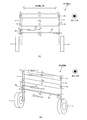
- FIG. 2 is an extracted view of the turning mechanism 10 of the vehicle 1 according to the embodiment of the present invention.
- 2 shows the turning mechanism 10 as viewed from the front of the vehicle 1.
- FIG. 2A shows the state of the turning mechanism 10 when the vehicle 1 goes straight, and
- FIG. The state of the turning mechanism 10 when turning rightward is shown.
- the inclination angle ⁇ is also defined as an inclination angle around the roll axis of the vehicle body of the vehicle 1.
- T 1 and T 1 on the tie rod 60 side are displaced to the left, and the right front wheel 11 and the left front wheel 12 connected via the tie rod 60 advance by leaning of the vehicle body 3 as shown in FIG.
- the vehicle is steered so as to travel in the same direction as
- the damper 70 attached to the tie rod 60 causes the damper 70 to generate torque for steering the right front wheel 11 and the left front wheel 12 as the D 1 pushes in the damper 70.
- the position of D 1 on the damper 70 side can be appropriately adjusted by changing the characteristics of the damper 70, for example.
- the steering operation of the right front wheel 11 and the left front wheel 12 can be adjusted by the damper 70 functioning as a torque applying unit that applies a steering torque.
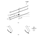
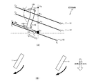
- FIG. 3A schematically shows a turning mechanism 10 corresponding to FIG. 2A
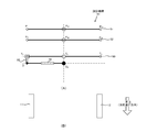
- FIG. 4A schematically shows a turning mechanism 10 corresponding to FIG. 2B
- FIG. 3B is a top view of the steering of the right front wheel 11 and the left front wheel 12 when the turning mechanism 10 is in the state of FIG.
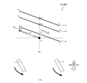
- the turning mechanism 10 according to the present invention is expressed by the method shown in FIGS. 3 and 4.
- FIG. 4 shows a case where the turning mechanism 10 has taken a lean operation for turning rightward, but at this time, the amount of resistance that D 1 of the damper link 80 resists the force pushing the damper 70 is included. Steering is performed while the steering torque is applied to the right front wheel 11 and the left front wheel 12.
- FIG. 5 shows a case where the turning mechanism 10 takes a lean operation for turning leftward. At this time, steering is performed while the steering torque including the amount that D 1 of the damper link 80 resists the force pulling the damper 70 is applied to the front wheel 11 and the left front wheel 12.
- this embodiment includes torque according to the inclination angular velocity (d ⁇ / dt). It can be seen that the steering torque can be applied to the right front wheel 11 and the left front wheel 12 that are the steering wheels.
- the steering direction of the steered wheels is steered so that the right front wheel 11 and the left front wheel 12 are in the same direction as the travel direction (operation direction) of the vehicle body 3 lean. Therefore, a configuration for solving (Problem 1) is provided.
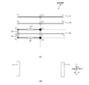
- 6 and 7 are views schematically showing the turning mechanism 10 of the vehicle 1 according to the second embodiment of the present invention.
- FIG. 6 is a schematic diagram of the turning mechanism 10 when the vehicle 1 goes straight
- FIG. 7 is a schematic view of the turning mechanism 10 when the vehicle body 3 is tilted to the right side so that the vehicle 1 turns rightward. Show.
- the turning mechanism 10 of the vehicle 1 according to the second embodiment of the present invention is different from that of the first embodiment in that the configuration related to the damper 70 is provided above the tie rod 60 in the first embodiment.
- the configuration related to the damper 70 is provided below the tie rod 60.
- the steering torque including the amount that the D 1 of the damper link 80 resists the force pulling the damper 70 is applied to the front wheels 11 and left.
- Steering is performed while being applied to the front wheels 12.
- the tie rod 60 attached to the damper link 80 is displaced in the right direction, and a steering angle that travels in the direction opposite to the direction traveled by the lean of the vehicle body 3 is given to the right front wheel 11 and the left front wheel 12. The It is possible to reproduce the state when the reverse handle is turned.
- the steering direction of the steered wheels is steered so that the right front wheel 11 and the left front wheel 12 are in a direction opposite to the direction (operation direction) of traveling by the lean of the vehicle body 3. Therefore, a configuration for solving (Problem 2) is provided.
- the steering torque that can be adjusted by the torque applying unit related to the damper 70 is the steering angle direction and / or the steering operation speed. You can see from the comparison.
- 8 and 9 are views schematically showing the turning mechanism 10 of the vehicle 1 according to the third embodiment of the present invention.
- FIG. 8 is a schematic diagram of the turning mechanism 10 when the vehicle 1 goes straight
- FIG. 9 is a schematic view of the turning mechanism 10 when the vehicle body 3 is tilted to the right side so that the vehicle 1 turns right. Show.
- the turning mechanism 10 of the vehicle 1 according to the third embodiment of the present invention is different from that of the first embodiment in that the configuration related to the damper 70 is a tie rod 60 via a damper link 80 in the first embodiment.
- the configuration related to the damper 70 is directly connected and connected to the tie rod 60.
- the steering torque including the amount that the D 1 of the damper link 80 resists the force pulling the damper 70 is applied to the front wheels 11 and left.
- Steering is performed while being applied to the front wheels 12.
- the tie rod 60 attached to the damper link 80 is displaced in the right direction, and a steering angle that travels in the same direction as that traveled by the lean of the vehicle body 3 is given to the right front wheel 11 and the left front wheel 12.
- the steering direction of the steered wheels is steered so that the right front wheel 11 and the left front wheel 12 are in the same direction as the travel direction (operation direction) of the vehicle body 3 lean. Therefore, a configuration for solving (Problem 1) is provided.
- 10 and 11 are views schematically showing a turning mechanism 10 of the vehicle 1 according to the fourth embodiment of the present invention.
- the turning mechanism 10 of the vehicle 1 according to the fourth embodiment of the present invention is different from that of the first embodiment in that the configuration related to the damper 70 is a tie rod 60 via the damper link 80 in the first embodiment.
- the configuration related to the damper 70 and the tie rod 60 are provided so as to cross each other.
- the steering torque including the amount that the D 1 of the damper link 80 resists the force pulling the damper 70 is applied to the front wheel 11, the left Steering is performed while being applied to the front wheels 12.
- the tie rod 60 attached to the damper link 80 is displaced in the right direction, and a steering angle that travels in the direction opposite to the direction traveled by the lean of the vehicle body 3 is given to the right front wheel 11 and the left front wheel 12. The It is possible to reproduce the state when the reverse handle is turned.
- the steering direction of the steered wheels is steered so that the right front wheel 11 and the left front wheel 12 are in a direction opposite to the direction (operation direction) of traveling by the lean of the vehicle body 3. Therefore, a configuration for solving (Problem 2) is provided.
- FIG. 12 is a diagram schematically showing the turning mechanism 10 of the vehicle 1 according to the fifth embodiment of the present invention.
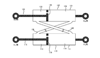
- FIG. 13 is a view for explaining the connection between the first damper 110 and the second damper 120 in the turning mechanism 10 of the vehicle 1 according to the fifth embodiment of the present invention.
- dampers the first damper 110 and the second damper 120.
- the first damper 110 is attached to the tie rod 60 as illustrated.
- the damper link 80 is not used.
- the second damper 120 is attached to the first horizontal link 51 as shown in the figure, for example.
- the first damper 110 has a configuration in which a cylinder 111 is filled with a viscous fluid such as oil, and a piston 118 provided with a through hole moves in the viscous fluid.
- the piston 118 separates the cylinder 111 into a first chamber 113 and a second chamber 114.
- a damping force as a damper is generated by the resistance of the viscous fluid when the piston 118 moves.
- the second damper 120 is configured such that the cylinder 121 is filled with a viscous fluid such as oil, and the piston 128 provided with a through hole moves in the viscous fluid.
- the piston 128 isolates the cylinder 121 into a third chamber 123 and a fourth chamber 124.
- a damping force as a damper is generated by the resistance of the viscous fluid when the piston 128 moves.
- the two dampers as described above are used, and the first chamber 113 of the first damper 110 and the third chamber 123 of the second damper 120 are connected by the first flow pipe 130.
- the second chamber 114 of the first damper 110 and the fourth chamber 124 of the second damper 120 are connected by the second flow pipe 140 so that the viscous fluid can be exchanged between the two dampers. ing.
- the steering direction of the steered wheels is steered so that the right front wheel 11 and the left front wheel 12 are in the same direction as the travel direction (operation direction) of the vehicle body 3 lean. Therefore, a configuration for solving (Problem 1) is provided.
- the first damper 110 and the second damper 120 when the first damper 110 and the second damper 120 are connected, the first chamber 113 of the first damper 110 and the fourth chamber 124 of the second damper 120 are connected to the first flow pipe. 130, the second chamber 114 of the first damper 110 and the third chamber 123 of the second damper 120 are connected by the second flow pipe 140, and the viscous fluid can be exchanged between the two dampers. As a result, a steering torque that is in the direction opposite to the direction (operation direction) that travels due to leaning of the vehicle body 3 is applied to the right front wheel 11 and the left front wheel 12.
- the right front wheel 11 and the left front wheel 12 are steered so as to be in a direction opposite to the direction (operation direction) of traveling by the lean of the vehicle body 3, and (Problem 2)
- a configuration for solving the problem can be provided.
- 16 and 17 are views schematically showing the turning mechanism 10 of the vehicle 1 according to the sixth embodiment of the present invention.
- FIG. 16 shows a schematic diagram of the turning mechanism 10 when the vehicle 1 goes straight
- FIG. 17 shows a schematic diagram of the turning mechanism 10 when the vehicle body 3 tilts to the right side so that the vehicle 1 turns rightward. Show.
- the configuration related to the first damper 110 is provided above the tie rod 60, and the configuration related to the second damper 120 is provided below the tie rod 60. It is the composition which was made.
- a damper link 80 that maintains both the distance between D 11 and T 1 and the distance between D 21 and T 1 is attached.
- the upper portion of the damper link 80 is attached between D 11 on the first damper 110 side and T 1 on the tie rod 60 side.
- D 21 on the second damper 120 side and T 1 on the tie rod 60 side are The lower part of the damper link 80 is also attached between the two.
- the characteristic of resistance generated according to the piston moving speed of the first damper 110 and the characteristic of resistance generated according to the piston moving speed of the second damper 120 are set to be different.
- properties that make the sum of characteristics and properties of the second damper 120 of the first damper 110, by acting on the T 1 of the tie rod 60 side, the right front wheel 11 steering torque, is configured to impart to the left front wheel 12 ing.
- FIG. 18 is a diagram for explaining a characteristic composed of the sum of the characteristic of the first damper 110 and the characteristic of the second damper 120, and the solid line indicates the sum of the characteristics of the two dampers.
- the horizontal axis represents the angular velocity of the inclination angle of the vehicle body 3.
- the solid line in FIG. 18 takes a positive value when the inclination angular velocity of the vehicle body 3 is slower than a predetermined value, and takes a negative value when the inclination angular velocity of the vehicle body 3 is greater than or equal to a predetermined value. Yes. That is, the direction of the steering torque applied to the right front wheel 11 and the left front wheel 12 can be changed according to the value of the inclination angular velocity of the vehicle body 3.
- the same direction as the traveling direction due to the inclination of the vehicle body 3 is used.
- the traveling direction is determined by the inclination of the vehicle body 3
- the right front wheel 11 and the left front wheel 12 are set to be steered so as to travel in the reverse direction.
- the right front wheel 11 and the left front wheel 12 are in the same direction as the traveling direction (operation direction) due to leaning of the vehicle body 3. While the steering direction of the steered wheel is steered and the wheel is delayed in following the lean of the vehicle body 3, the response of turning is deteriorated (Problem 1), while at the same time, the vehicle 1
- the steering direction of the steered wheels is steered so that the right front wheel 11 and the left front wheel 12 are in the direction opposite to the direction (operation direction) of traveling by the lean of the vehicle body 3. It is possible to solve (Problem 2) that the inertial force according to the angular velocity acts on the driver and hinders the driving operation.
- FIG. 19 is a diagram schematically showing the turning mechanism 10 of the vehicle 1 according to the seventh embodiment of the present invention.
- FIG. 20 is a view for explaining the connection between the first damper 110 and the second damper 120 in the turning mechanism 10 of the vehicle 1 according to the seventh embodiment of the present invention.
- dampers the first damper 110 and the second damper 120
- the first damper 110 is attached to the tie rod 60 as illustrated.
- the second damper 120 is attached to the first horizontal link 51 as shown in the figure, for example.
- the first damper 110 and the second damper 120 are connected as shown in FIG. That is, when connecting the first damper 110 and the second damper 120, the first chamber 113 of the first damper 110 and the fourth chamber 124 of the second damper 120 are connected by the first flow pipe 130, and the first damper is connected.
- the second chamber 114 of 110 and the third chamber 123 of the second damper 120 are connected by the second flow pipe 140 so that the viscous fluid can be exchanged between the two dampers.
- a characteristic composed of the sum of the characteristics of the first damper 110 and the second damper 120 is applied to T 1 on the tie rod 60 side, as in the sixth embodiment.
- the steering torque can be applied to the right front wheel 11 and the left front wheel 12.
- the sum of the characteristics of the two dampers indicates that the inclination angular velocity of the vehicle body 3 is predetermined.
- a positive value is taken when the vehicle is slower than the value, a negative value is taken when the tilt angular velocity of the vehicle body 3 is equal to or greater than a predetermined value, and steering is applied to the right front wheel 11 and the left front wheel 12 according to the value of the tilt angular velocity of the vehicle body 3. It is possible to change the direction of the torque.
- the vehicle travels in the same direction as the traveling direction due to the inclination of the vehicle body 3.
- the right front wheel 11 and the left front wheel 12 are set to be steered and the angular velocity of the vehicle body 3 is equal to or greater than a predetermined value, the right front wheel 11. Set so that the left front wheel 12 is steered.
- the steering torque applied to the right front wheel 11 and the left front wheel 12 is adjusted according to the inclination angular velocity (d ⁇ / dt). in addition to be made according to the d [theta] / dt), it can also be performed according to the inclination angular acceleration (d 2 ⁇ / dt 2) .
- FIG. 21 is a diagram for explaining the outline of the control pattern of the vehicle 1 according to the present invention.
- the control pattern of the embodiment described so far will be referred to as pattern (I).
- the steering torque in the “reverse direction” is suitable as control for preventing the driving operation of the driver from being hindered by the influence of lean of the vehicle body 3.
- the steering torque in the “reverse direction” is the pattern (II)
- the lateral G is not generated in the driver's body. This is suitable as a control that provides a comfortable ride.
- the steering torque in the “same direction” is suitable as control for realizing the vehicle behavior desired by the driver when the vehicle 1 starts to move or immediately before the vehicle 1 stops.
- Pattern (III) and pattern (IV) determine the steering direction of the steered wheels based on the inclination angular acceleration (d 2 ⁇ / dt 2 ).
- the steering torque is “same direction” in the pattern (III), it is suitable as control for preventing the follow-up of the vehicle body 3 to the lean from being delayed and improving the turning response of the vehicle 1. Further, the steering torque in the “reverse direction” is suitable as control for preventing the driving operation of the driver from being hindered by the influence of lean of the vehicle body 3.
- the steering torque in the “reverse direction” is the pattern (IV)
- the lateral G is not generated in the driver's body. This is suitable as a control that provides a comfortable ride.
- the steering torque in the “same direction” is suitable as control for realizing the vehicle behavior desired by the driver when the vehicle 1 starts to move or immediately before the vehicle 1 stops.
- the steering torque characteristics (direction and magnitude) of the steered wheels are changed according to the tilt angular velocity (d ⁇ / dt) and the tilt angular acceleration (d 2 ⁇ / dt 2 ).
- d ⁇ / dt tilt angular velocity
- d 2 ⁇ / dt 2 tilt angular acceleration
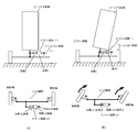
- FIG. 22 is a view for explaining the relationship between the handle 7 as an input member and the turning mechanism 10.
- FIG. 22 is a diagram schematically showing the vehicle 1 from the front.
- FIG. 22 illustrates the state of the turning mechanism 10 and the handle 7 for indicating the direction thereof from the front.
- the handle 7 is intentionally operated by a driver (not shown).
- FIG. 22A shows the operation of the driver intended to go straight and the state of the turning mechanism 10 at that time.
- FIG. 22B shows the state of the turning mechanism 10 when the driver turns the steering wheel 7 to the right with the intention of turning right (the drawing shows the vehicle 1 as viewed from the front). Since the handle 7 is cut to the left side, it is illustrated.
- the vehicle body tilts to the right side at an inclination angle ⁇ according to the turning angle of the handle 7, and the right front wheel 11 and the left front wheel 12 to which steering torque is applied rotate to the right side. To do.
- FIG. 23 shows a state in which the right front wheel 11 has got on an obstacle, for example, even though the driver is operating the handle 7 to go straight ahead.
- the turning mechanism 10 has a posture similar to the state when turning right, and as a result, there is a problem that a steering torque in the “right direction” is generated.
- the input state of the driver from the handle 7 in the vehicle 1 and the operation of the turning mechanism 10 are all performed electrically.
- the adjustment of the steering torque is realized by an electric mechanism including a sensor and an actuator.
- FIG. 24 is a diagram showing a block configuration for electrically realizing the control of the vehicle 1 according to the present invention.
- the components that are not necessary for the control of the present invention are not shown.
- the vehicle ECU 300 cooperates and operates with each component connected to the vehicle ECU 100 shown in the figure. Further, the vehicle ECU 300 executes various control processes in the vehicle 10 of the present invention based on programs and data stored and held in storage means such as a ROM in the vehicle ECU 100.
- the rotational drive device ECU 301 that controls the rear wheel rotational drive device 213 based on the command value output from the vehicle ECU 300 and the lean value based on the command value output from the vehicle ECU 100.
- a lean motor ECU 302 that controls a motor 225 (not shown) and a steering motor ECU 303 that controls a steering motor 265 based on a command value output from the vehicle ECU 100 are provided.
- the rear wheel rotation drive device 213 drives the rear wheel 13 to rotate
- the lean motor 225 is a motor for setting the vehicle body inclination angle ⁇ (the inclination angle ⁇ of the first horizontal link 51) as a command value.
- the steering motor 265 is a motor that applies a steering torque based on the command value to the steered wheels (the right front wheel 11 and the left front wheel 12).
- the steering motor 265 functions as a steering actuator.
- the input member such as the handle 7 is operated by the driver to turn the vehicle.
- the input member operation angle sensor 323 detects a cutting angle of the input member, and the operation angle data of the handle 7 detected by the input member operation angle sensor 323 is input to the vehicle ECU 100.
- the input member operation angle sensor 323 includes, for example, an encoder.
- the lean motor 225 includes an inclination angle sensor 325 that detects a change in the inclination angle ⁇ of the first horizontal link 51.
- the tilt angle sensor 325 is a rotation angle sensor that detects the rotation angle of the rotation shaft with respect to the body in the lean motor 225, and includes, for example, a resolver, an encoder, and the like.
- the inclination angle ⁇ detected by the inclination angle sensor 325 is input to the vehicle ECU 100.
- the vehicle body of the vehicle 1 is provided with a gyro sensor 326. According to such a gyro sensor 326, at least the direction of gravitational acceleration can be grasped on the vehicle ECU 100 side.
- control of the vehicle 1 according to the present invention (control for changing the steering torque characteristics (direction and magnitude) of the steered wheels according to the tilt angular velocity and the tilt angular acceleration) can be electrically realized. It becomes possible.
- the vehicle ECU 100 determines that the right front wheel 11 and the left in the turning mechanism 10 are based on information obtained from the input member operation angle sensor 323, the tilt angle sensor 325, and the gyro sensor 326.
- the adjustment operation of the steering torque applied to the front wheels 12, that is, the control operation of the lean motor 225 and the steering motor 265 is determined.
- the vehicle ECU 100 steers the right front wheel 11 and the left front wheel 12 in accordance with the time change of the tilt angle ⁇ of the vehicle body, that is, the direction of the tilt angular velocity (d ⁇ / dt).
- the steering angle direction at is determined.
- FIG. 25 is a diagram showing the relationship between the tilt angular velocity (d ⁇ / dt) and the steering angle direction of the right front wheel 11 and the left front wheel 12 in the vehicle 1.
- FIG. 25 is a diagram showing the relationship between the tilt angular velocity (d ⁇ / dt) and the steering angle direction of the right front wheel 11 and the left front wheel 12 in the vehicle 1.
- the direction of the inclination angular velocity (d ⁇ / dt) and the steering direction of the steered wheels (the right front wheel 11 and the left front wheel 12) are set to the same direction. It is a feature. That is, with respect to the relationship between the direction of the tilt angular velocity (d ⁇ / dt) and the steering torque, as shown in FIG. 25, control is performed so that the first quadrant and the third quadrant are always entered.
- the turning mechanism 10 is not in the right turning posture as shown in FIG. 23, and the posture of the turning mechanism 10 is determined based on the control value by the input member operation angle sensor 323 based on the turning angle of the handle 7 to the last. Therefore, for example, the tilting movement of the vehicle body such as the obstacle as described above is suppressed, and the running is stabilized.
- the vehicle 1 when the vehicle 1 is controlled with respect to the vehicle 1 by the electric mechanism as described above, the vehicle 1 can perform a stable running against an obstacle or the like.
- the mechanism 10 When the mechanism 10 converges to the target tilt angle, there is a problem that a feeling of rocking that is not intended by the driver occurs.
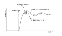
- FIG. 27 is a diagram illustrating control based on the relationship between the target tilt angle value and the actual tilt angle in the turning mechanism 10.
- the horizontal axis represents the time axis
- the vertical axis represents the tilt angle ⁇ in the turning mechanism 10.
- the dotted line indicates the target value of the inclination angle ⁇ with respect to the handle 7 being cut by the driver.
- the solid line indicates the behavior of the actual inclination angle acquired from the inclination angle sensor 325.
- FIG. 28 is a diagram schematically showing a turning mechanism 10 of a vehicle 1 according to another embodiment of the present invention.
- the expansion / contraction member that expands and contracts according to the inclination is a mechanism that directly applies the steering torque to the steering wheel, but the turning mechanism in the vehicle 1 according to the present invention.
- the point which has two expansion-contraction members of (2)) is different.
- the turning mechanism 10 includes a piston device (1) that receives a force from a leaning element such as the vehicle body 3, and includes a piston device (2) that transmits a force to the link mechanism in relation to the steered wheels.
- a leaning element such as the vehicle body 3
- the piston device (2) that transmits a force to the link mechanism in relation to the steered wheels.
- the oil chambers of the piston devices are connected.
- FIG. 28A shows the vehicle 1 that goes straight
- FIG. 28B shows the vehicle 1 that turns right.
- FIG. 28 (B) when the vehicle body in the vehicle is tilted, the oil chamber x of the piston device (1) is compressed, and the pumped oil is compressed into the cylinder of the piston device (2) (the oil chamber on the right side of the drawing). ).
- the piston of the piston device (2) moves to the left in the figure, and the steering wheel is steered by the link mechanism connected to the piston.
- piston device (1) and the piston device (2) can be regarded as having the same function as a telescopic member such as a damper.
- the vehicle according to the present invention has the torque applying unit that applies the steering torque to the steered wheels according to the inclination angular velocity or the inclination angular acceleration of the vehicle body. According to this, the problem that the wheel follows the lean of the vehicle body is delayed, and the response of turning deteriorates, and the inertial force according to the angular velocity of the inclination angle of the vehicle body acts on the driver, and the driving operation It is possible to solve either or both of the problems of obstructing the problem.
- the direction of the inclination angular velocity (d ⁇ / dt) and the steering direction of the steered wheels (the right front wheel 11 and the left front wheel 12) have been made the same direction.
- the steering torque may be applied in the direction opposite to the inclination angular velocity.
- the present invention relates to a miniaturized vehicle that has recently attracted attention from the viewpoint of energy problems.
- the wheel when the vehicle body leans, the wheel has a steering angle that follows the lean of the vehicle body, and when the vehicle is configured to turn, the steering angle of the wheel follows the lean of the vehicle body.
- the response to turning is deteriorated due to the phenomenon that the vehicle is delayed, or the lean speed of the vehicle body is very high, the inertia corresponding to the angular velocity of the vehicle body tilt angle
- force acts on the driver and hinders driving.
- the vehicle according to the present invention has a torque applying unit that applies a steering torque to the steered wheels in accordance with the inclination angular velocity or the inclination angular acceleration of the vehicle body.
- a torque applying unit that applies a steering torque to the steered wheels in accordance with the inclination angular velocity or the inclination angular acceleration of the vehicle body.
- piston rod 118 Piston 120 ... Second damper 121 ... Cylinder 123 ... 3rd chamber 124 ... 4th chamber 125 ... piston rod 128 ... piston 130 ... first flow pipe 140 ... second flow pipe 213 ... rear wheel rotation drive device 225 ... lean Motor 265 ... steering motor 300 ... vehicle ECU 301 ... Rotary drive unit ECU 302 ... Lean motor ECU 303 ... Steering motor ECU 323 ... Input member operation angle sensor 325 ... Tilt angle sensor 326 ... Gyro sensor
Landscapes
- Engineering & Computer Science (AREA)
- Mechanical Engineering (AREA)
- Physics & Mathematics (AREA)
- General Physics & Mathematics (AREA)
- Chemical & Material Sciences (AREA)
- Combustion & Propulsion (AREA)
- Transportation (AREA)
- Radar, Positioning & Navigation (AREA)
- Remote Sensing (AREA)
- Automatic Cycles, And Cycles In General (AREA)
- Vehicle Body Suspensions (AREA)
- Steering-Linkage Mechanisms And Four-Wheel Steering (AREA)
Abstract
Description
特許文献1(特表2014-524864号公報)には、車両100が旋回しているときに、シャーシ102とほぼ同じ角度で傾くフロント・ホイール106を有する三輪車両100が開示されている。
3・・・車体
5・・・座席
7・・・ハンドル
10・・・旋回機構
11・・・右前輪
12・・・左前輪
13・・・後輪
15・・・中央棹
17・・・中央棹延出部
21・・・右懸架棹
22・・・左懸架棹
25・・・中央管
31・・・右懸架腕
32・・・左懸架腕
41・・・右前輪車軸
42・・・左前輪車軸
51・・・第1水平リンク
52・・・第2水平リンク
60・・・タイロッド
70・・・ダンパ
71・・・シリンダ
72・・・シリンダ側取付部
75・・・ピストンロッド
76・・・ピストンロッド側取付部
80・・・ダンパリンク
110・・・第1ダンパ
111・・・シリンダ
113・・・第1室
114・・・第2室
115・・・ピストンロッド
118・・・ピストン
120・・・第2ダンパ
121・・・シリンダ
123・・・第3室
124・・・第4室
125・・・ピストンロッド
128・・・ピストン
130・・・第1流通管
140・・・第2流通管
213・・・後輪回転駆動装置
225・・・リーンモータ
265・・・操舵モータ
300・・・車両ECU
301・・・回転駆動装置ECU
302・・・リーンモータECU
303・・・操舵モータECU
323・・・入力部材操作角センサ
325・・・傾斜角センサ
326・・・ジャイロセンサ
Claims (14)
- 操舵を行う操舵輪が含まれる2つ以上の車輪が設けられた車体と、
前記車体のロール軸まわりの傾斜角を検出する傾斜角検出部と、
前記傾斜角より求めた前記車体の傾斜角速度又は傾斜角加速度に応じて、前記操舵輪に対して操舵トルクを付与するトルク付与部と、
を有することを特徴とする車両。 - 前記トルク付与部は、前記車体の傾斜角速度に応じて、前記操舵輪の舵角方向及び/又は操舵動作速度を調整することを特徴とする請求項2に記載の車両。
- 前記トルク付与部は、前記車体の傾斜角速度の方向と、同方向に操舵トルクを付与することを特徴とする請求項1又は請求項2に記載の車両。
- 前記トルク付与部は、
前記車体の傾斜角速度が所定値より遅い場合には、該傾斜角速度の方向と同方向に操舵トルクを付与し、
前記車体の傾斜角速度が所定値以上である場合には、該傾斜角速度の方向と逆方向に操舵トルクを付与することを特徴とする請求項3に記載の車両。 - 前記トルク付与部には、前記車体の傾斜に応じて伸縮する伸縮部材が用いられることを特徴とする請求項1乃至請求項4に記載の車両。
- 前記傾斜角検出部は、車体の傾斜角に応じて伸縮する第1の伸縮部材とされ、
前記トルク付与部は、該第1の伸縮部材に連動して、前記操舵輪に対して操舵トルクを付与する第2の伸縮部材を有することを特徴とする請求項5に記載の車両。 - 前記第1の伸縮部材と前記第2の伸縮部材は同じ部材であることを特徴とする請求項6に記載の車両。
- 一対の前記操舵輪を懸架する一対の懸架腕を収容する一対の懸架棹と、
前記一対の懸架棹と平行リンクをなす一対の水平リンクと、
前記操舵輪の操舵角を揃えるタイロッドと、を有し、
前記トルク付与部には、
前記タイロッドとダンパリンクを介して一端が接続されると共に、他端が前記車体に接続されるダンパが含まれることを特徴とする請求項1に記載の車両。 - 一対の前記操舵輪を懸架する一対の懸架腕を収容する一対の懸架棹と、
前記一対の懸架棹と平行リンクをなす一対の水平リンクと、
一対の前記操舵輪の操舵角を揃えるタイロッドと、を有し、
前記トルク付与部には、
前記タイロッドとダンパリンクを介して一端が接続されると共に、他端が前記車体に接続される第1ダンパと、
前記水平リンクと一端が接続されると共に、他端が前記車体に接続される第2ダンパと、
前記第1ダンパ中の流体と、前記第2ダンパ中の流体とを流通させる一対の流通管と、
が含まれることを特徴とする請求項1に記載の車両。 - 前記第1ダンパのピストンの移動速度に応じて生じる抵抗の特性と、
前記第2ダンパのピストンの移動速度に応じて生じる抵抗の特性と、が異なることを特徴とする請求項9に記載の車両。 - 旋回方向を入力する入力部材と、
前記操舵輪を操舵する操舵部材と、
が機械的に半接続状態で繋がれていることを特徴とする請求項1乃至請求項10のいずれか1項に記載の車両。 - 旋回方向を入力する入力部材と、
前記操舵輪を操舵する操舵部材と、
が機械的に完全に分離していることを特徴とする請求項1乃至請求項10のいずれか1項に記載の車両。 - 前記トルク付与部に対する制御指令を発する制御部を有し、
前記制御部は、前記車体の傾斜角速度に応じて、前記操舵輪の舵角方向及び/又は操舵動作速度を調整するように前記トルク付与部に対して制御指令を発することを特徴とする請求項1に記載の車両。 - 前記トルク付与部は、
目標傾斜角から実際の傾斜角が遠ざかっている場合には、前記の調整を行い、
目標傾斜角に実際の傾斜角が近づいている場合には、前記の調整を行わない、あるいは、弱めることを特徴とする請求項13に記載の車両。
Priority Applications (4)
| Application Number | Priority Date | Filing Date | Title |
|---|---|---|---|
| CN201880032875.6A CN110650887B (zh) | 2017-05-19 | 2018-05-21 | 车辆 |
| EP18802317.0A EP3628578B1 (en) | 2017-05-19 | 2018-05-21 | Vehicle |
| US16/615,056 US11472474B2 (en) | 2017-05-19 | 2018-05-21 | Vehicle |
| JP2019518908A JP7227566B2 (ja) | 2017-05-19 | 2018-05-21 | 車両 |
Applications Claiming Priority (2)
| Application Number | Priority Date | Filing Date | Title |
|---|---|---|---|
| JP2017100275 | 2017-05-19 | ||
| JP2017-100275 | 2017-05-19 |
Publications (1)
| Publication Number | Publication Date |
|---|---|
| WO2018212360A1 true WO2018212360A1 (ja) | 2018-11-22 |
Family
ID=64273934
Family Applications (1)
| Application Number | Title | Priority Date | Filing Date |
|---|---|---|---|
| PCT/JP2018/019500 Ceased WO2018212360A1 (ja) | 2017-05-19 | 2018-05-21 | 車両 |
Country Status (5)
| Country | Link |
|---|---|
| US (1) | US11472474B2 (ja) |
| EP (1) | EP3628578B1 (ja) |
| JP (1) | JP7227566B2 (ja) |
| CN (1) | CN110650887B (ja) |
| WO (1) | WO2018212360A1 (ja) |
Cited By (5)
| Publication number | Priority date | Publication date | Assignee | Title |
|---|---|---|---|---|
| JP2020164136A (ja) * | 2019-03-29 | 2020-10-08 | 株式会社エクォス・リサーチ | 車両 |
| WO2021132705A1 (ja) * | 2019-12-27 | 2021-07-01 | 株式会社エクォス・リサーチ | 車両 |
| WO2021132706A1 (ja) * | 2019-12-27 | 2021-07-01 | 株式会社エクォス・リサーチ | 車両 |
| KR20220068548A (ko) * | 2020-11-19 | 2022-05-26 | 현대자동차주식회사 | 독립 현가 시스템 |
| KR20220068550A (ko) * | 2020-11-19 | 2022-05-26 | 현대자동차주식회사 | 독립 현가 시스템 |
Families Citing this family (2)
| Publication number | Priority date | Publication date | Assignee | Title |
|---|---|---|---|---|
| US12017629B2 (en) * | 2019-09-19 | 2024-06-25 | Steering Solutions Ip Holding Corporation | Vehicle wheel steer control system and method |
| CN111409748B (zh) * | 2020-03-23 | 2021-08-17 | 苏州盱酋汽车科技有限公司 | 倒三轮车自动侧倾控制方法 |
Citations (6)
| Publication number | Priority date | Publication date | Assignee | Title |
|---|---|---|---|---|
| WO2005075278A1 (en) | 2004-02-06 | 2005-08-18 | Phillip Ronald James | Tilting vehicle |
| JP2009083578A (ja) * | 2007-09-28 | 2009-04-23 | Honda Motor Co Ltd | ステアリング補助システム及びステアリング補助方法 |
| JP2011073624A (ja) * | 2009-09-30 | 2011-04-14 | Honda Motor Co Ltd | 自動二輪車の操舵装置 |
| JP2013112238A (ja) * | 2011-11-30 | 2013-06-10 | Equos Research Co Ltd | 車両 |
| JP2013208974A (ja) * | 2012-03-30 | 2013-10-10 | Kyb Co Ltd | 懸架装置 |
| JP2014524864A (ja) | 2011-07-07 | 2014-09-25 | アンドリュー ゲール、デイビッド | 車両 |
Family Cites Families (12)
| Publication number | Priority date | Publication date | Assignee | Title |
|---|---|---|---|---|
| BRPI0600397A (pt) * | 2005-02-24 | 2006-10-24 | Honda Motor Co Ltd | sistema de direcionamento acionado por energia elétrica para veìculo quadriciclo do tipo bugre |
| CA2610615C (en) | 2005-05-31 | 2014-02-04 | Brinks Westmaas B.V. | Self-balancing vehicle |
| WO2011059456A1 (en) * | 2009-11-16 | 2011-05-19 | Bombardier Recreational Products Inc. | Leaning vehicle with tilting front wheels and suspension therefor |
| RU2505432C2 (ru) * | 2009-08-18 | 2014-01-27 | Тойота Дзидося Кабусики Кайся | Система управления транспортного средства |
| JP2012166637A (ja) | 2011-02-14 | 2012-09-06 | Equos Research Co Ltd | 車両 |
| DE102012205520A1 (de) | 2012-04-04 | 2013-10-10 | Robert Bosch Gmbh | Verfahren zur Lenkmomentreduzierung bei Kurvenfahrten eines Zweirads |
| JP6572586B2 (ja) | 2015-03-27 | 2019-09-11 | スズキ株式会社 | 電動二輪車の走行制御装置およびその走行制御方法 |
| JP6450267B2 (ja) * | 2015-06-23 | 2019-01-09 | 本田技研工業株式会社 | 移動体 |
| WO2017090666A1 (ja) | 2015-11-24 | 2017-06-01 | ヤマハ発動機株式会社 | リーン車両 |
| JP6557841B2 (ja) * | 2016-08-29 | 2019-08-14 | 株式会社エクォス・リサーチ | 車両 |
| JP2020075518A (ja) | 2017-03-14 | 2020-05-21 | ヤマハ発動機株式会社 | 前二輪逆操舵リーン車両 |
| JP7327300B2 (ja) * | 2020-07-02 | 2023-08-16 | トヨタ自動車株式会社 | スタビライザの制御装置 |
-
2018
- 2018-05-21 JP JP2019518908A patent/JP7227566B2/ja active Active
- 2018-05-21 WO PCT/JP2018/019500 patent/WO2018212360A1/ja not_active Ceased
- 2018-05-21 CN CN201880032875.6A patent/CN110650887B/zh active Active
- 2018-05-21 EP EP18802317.0A patent/EP3628578B1/en active Active
- 2018-05-21 US US16/615,056 patent/US11472474B2/en active Active
Patent Citations (6)
| Publication number | Priority date | Publication date | Assignee | Title |
|---|---|---|---|---|
| WO2005075278A1 (en) | 2004-02-06 | 2005-08-18 | Phillip Ronald James | Tilting vehicle |
| JP2009083578A (ja) * | 2007-09-28 | 2009-04-23 | Honda Motor Co Ltd | ステアリング補助システム及びステアリング補助方法 |
| JP2011073624A (ja) * | 2009-09-30 | 2011-04-14 | Honda Motor Co Ltd | 自動二輪車の操舵装置 |
| JP2014524864A (ja) | 2011-07-07 | 2014-09-25 | アンドリュー ゲール、デイビッド | 車両 |
| JP2013112238A (ja) * | 2011-11-30 | 2013-06-10 | Equos Research Co Ltd | 車両 |
| JP2013208974A (ja) * | 2012-03-30 | 2013-10-10 | Kyb Co Ltd | 懸架装置 |
Cited By (12)
| Publication number | Priority date | Publication date | Assignee | Title |
|---|---|---|---|---|
| JP2020164136A (ja) * | 2019-03-29 | 2020-10-08 | 株式会社エクォス・リサーチ | 車両 |
| JP7193780B2 (ja) | 2019-03-29 | 2022-12-21 | 株式会社アイシン | 車両 |
| WO2021132705A1 (ja) * | 2019-12-27 | 2021-07-01 | 株式会社エクォス・リサーチ | 車両 |
| WO2021132706A1 (ja) * | 2019-12-27 | 2021-07-01 | 株式会社エクォス・リサーチ | 車両 |
| JPWO2021132705A1 (ja) * | 2019-12-27 | 2021-07-01 | ||
| JPWO2021132706A1 (ja) * | 2019-12-27 | 2021-07-01 | ||
| JP7290175B2 (ja) | 2019-12-27 | 2023-06-13 | 株式会社アイシン | 車両 |
| JP7328628B2 (ja) | 2019-12-27 | 2023-08-17 | 株式会社アイシン | 車両 |
| KR20220068548A (ko) * | 2020-11-19 | 2022-05-26 | 현대자동차주식회사 | 독립 현가 시스템 |
| KR20220068550A (ko) * | 2020-11-19 | 2022-05-26 | 현대자동차주식회사 | 독립 현가 시스템 |
| KR102895278B1 (ko) | 2020-11-19 | 2025-12-03 | 현대자동차주식회사 | 독립 현가 시스템 |
| KR102895428B1 (ko) | 2020-11-19 | 2025-12-03 | 현대자동차주식회사 | 독립 현가 시스템 |
Also Published As
| Publication number | Publication date |
|---|---|
| US20200108861A1 (en) | 2020-04-09 |
| CN110650887B (zh) | 2022-01-11 |
| JPWO2018212360A1 (ja) | 2020-03-19 |
| US11472474B2 (en) | 2022-10-18 |
| JP7227566B2 (ja) | 2023-02-22 |
| EP3628578A4 (en) | 2021-03-10 |
| CN110650887A (zh) | 2020-01-03 |
| EP3628578B1 (en) | 2022-05-11 |
| EP3628578A1 (en) | 2020-04-01 |
Similar Documents
| Publication | Publication Date | Title |
|---|---|---|
| JP7227566B2 (ja) | 車両 | |
| US11014600B2 (en) | Leaning vehicle | |
| US11173979B2 (en) | Leaning vehicle | |
| US11014422B2 (en) | Leaning vehicle | |
| JP2020075557A (ja) | 減衰力可変ダンパの制御装置 | |
| WO2018168943A1 (ja) | 前二輪逆操舵リーン車両 | |
| EP1885593A2 (en) | Self-balancing vehicle | |
| JP2025522405A (ja) | フライホイールおよびステアリングによる車両のダイナミクス強化方法 | |
| JP3696466B2 (ja) | 車両用操舵装置 | |
| JP2010228621A (ja) | ステアリングダンパ装置 | |
| JP5151307B2 (ja) | サスペンション | |
| JP2009132378A (ja) | 車両及び制御装置 | |
| WO2023145321A1 (ja) | 傾斜車両 | |
| WO2023120572A1 (ja) | 傾斜車両 | |
| JP5476909B2 (ja) | 操舵装置 | |
| JP4238569B2 (ja) | パワーステアリング装置 | |
| JP7770279B2 (ja) | 移動体 | |
| JPS6185276A (ja) | 自動車の操向制御装置 | |
| WO2023145320A1 (ja) | 傾斜車両 | |
| JP2024046319A (ja) | 移動体 | |
| WO2026100114A1 (ja) | サスペンション制御装置 | |
| JP2016130035A (ja) | 電動パワーステアリング装置 | |
| JP2009090972A (ja) | 制御装置 |
Legal Events
| Date | Code | Title | Description |
|---|---|---|---|
| 121 | Ep: the epo has been informed by wipo that ep was designated in this application |
Ref document number: 18802317 Country of ref document: EP Kind code of ref document: A1 |
|
| ENP | Entry into the national phase |
Ref document number: 2019518908 Country of ref document: JP Kind code of ref document: A |
|
| NENP | Non-entry into the national phase |
Ref country code: DE |
|
| WWE | Wipo information: entry into national phase |
Ref document number: 2018802317 Country of ref document: EP |
|
| ENP | Entry into the national phase |
Ref document number: 2018802317 Country of ref document: EP Effective date: 20191219 |