WO2018216176A1 - 頭部装着型表示装置 - Google Patents
頭部装着型表示装置 Download PDFInfo
- Publication number
- WO2018216176A1 WO2018216176A1 PCT/JP2017/019590 JP2017019590W WO2018216176A1 WO 2018216176 A1 WO2018216176 A1 WO 2018216176A1 JP 2017019590 W JP2017019590 W JP 2017019590W WO 2018216176 A1 WO2018216176 A1 WO 2018216176A1
- Authority
- WO
- WIPO (PCT)
- Prior art keywords
- head
- display device
- mounted display
- axis
- visor
- Prior art date
- Legal status (The legal status is an assumption and is not a legal conclusion. Google has not performed a legal analysis and makes no representation as to the accuracy of the status listed.)
- Ceased
Links
Images





Classifications
-
- G—PHYSICS
- G02—OPTICS
- G02B—OPTICAL ELEMENTS, SYSTEMS OR APPARATUS
- G02B27/00—Optical systems or apparatus not provided for by any of the groups G02B1/00 - G02B26/00, G02B30/00
- G02B27/01—Head-up displays
- G02B27/017—Head mounted
-
- G—PHYSICS
- G02—OPTICS
- G02B—OPTICAL ELEMENTS, SYSTEMS OR APPARATUS
- G02B27/00—Optical systems or apparatus not provided for by any of the groups G02B1/00 - G02B26/00, G02B30/00
- G02B27/01—Head-up displays
- G02B27/017—Head mounted
- G02B27/0172—Head mounted characterised by optical features
-
- G—PHYSICS
- G02—OPTICS
- G02B—OPTICAL ELEMENTS, SYSTEMS OR APPARATUS
- G02B27/00—Optical systems or apparatus not provided for by any of the groups G02B1/00 - G02B26/00, G02B30/00
- G02B27/01—Head-up displays
- G02B27/017—Head mounted
- G02B27/0176—Head mounted characterised by mechanical features
-
- G—PHYSICS
- G02—OPTICS
- G02B—OPTICAL ELEMENTS, SYSTEMS OR APPARATUS
- G02B27/00—Optical systems or apparatus not provided for by any of the groups G02B1/00 - G02B26/00, G02B30/00
- G02B27/02—Viewing or reading apparatus
-
- H—ELECTRICITY
- H04—ELECTRIC COMMUNICATION TECHNIQUE
- H04N—PICTORIAL COMMUNICATION, e.g. TELEVISION
- H04N5/00—Details of television systems
- H04N5/64—Constructional details of receivers, e.g. cabinets or dust covers
-
- H—ELECTRICITY
- H04—ELECTRIC COMMUNICATION TECHNIQUE
- H04N—PICTORIAL COMMUNICATION, e.g. TELEVISION
- H04N5/00—Details of television systems
- H04N5/74—Projection arrangements for image reproduction, e.g. using eidophor
-
- H—ELECTRICITY
- H04—ELECTRIC COMMUNICATION TECHNIQUE
- H04N—PICTORIAL COMMUNICATION, e.g. TELEVISION
- H04N9/00—Details of colour television systems
- H04N9/12—Picture reproducers
- H04N9/31—Projection devices for colour picture display, e.g. using electronic spatial light modulators [ESLM]
-
- G—PHYSICS
- G02—OPTICS
- G02B—OPTICAL ELEMENTS, SYSTEMS OR APPARATUS
- G02B27/00—Optical systems or apparatus not provided for by any of the groups G02B1/00 - G02B26/00, G02B30/00
- G02B27/01—Head-up displays
- G02B27/0101—Head-up displays characterised by optical features
- G02B2027/013—Head-up displays characterised by optical features comprising a combiner of particular shape, e.g. curvature
-
- G—PHYSICS
- G02—OPTICS
- G02B—OPTICAL ELEMENTS, SYSTEMS OR APPARATUS
- G02B27/00—Optical systems or apparatus not provided for by any of the groups G02B1/00 - G02B26/00, G02B30/00
- G02B27/01—Head-up displays
- G02B27/0149—Head-up displays characterised by mechanical features
- G02B2027/0154—Head-up displays characterised by mechanical features with movable elements
Definitions
- the present invention relates to a display device that displays image information or the like as a virtual image in front of the user's eyes, and more particularly to a head-mounted display device that is used by the user wearing the head.
- HMD helmet-mounted display
- the HMD projects the image displayed on a display device such as a cathode ray tube (CRT) or liquid crystal display (LCD) onto the visor (shield) provided on the helmet worn by the operator on the head and reflects it back to the operator.
- a display image with a virtual image is formed in front of the driver's eyes.
- helmets for aircraft usually have a spherical visor shape.
- the spherical shape is the easiest to process when making a visor with high dimensional accuracy, that is, distortion as small as possible, and the spherical shape ensures high strength against large external forces due to acceleration. This is presumed to be due to reasons such as being easy. Therefore, in an aircraft HMD, an optical system is configured to reflect display light in a spherical visor.
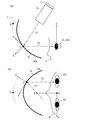
- FIG. 8 is a schematic configuration diagram of an optical system including a visor in a conventional HMD, in which (a) is a schematic longitudinal sectional view and (b) is a schematic transverse sectional view.
- the spherical visor 100 having a circular cross-sectional shape covers the user H's head, and slides up and down on a helmet (not shown) whose front side of the user H is open. It is installed as possible.
- the inner surface of the visor 100 facing the user H is a reflecting surface 100a.
- the reflecting surface 100a is formed with a coating layer that reflects part of the display light and transmits part of the light coming from the outside. ing.
- Display light emitted from the image display unit 101 that forms a display image is projected onto a predetermined area of the reflecting surface 100 a of the visor 100 by the projection optical system 102. Then, the reflected light reaches the eyes EL and ER of the user H. Further, part of light from the outside world that has passed through the visor 100 also reaches the eyes EL and ER of the user H. As a result, a virtual image based on the display image is formed in front of the eyes of the user H so as to be superimposed on the scene of the outside world (see Patent Document 1).
- the projection optical system 102 normally collimates the display light emitted from the image display unit 110 and projects it onto the reflection surface of the visor 100.
- the optical axis of the luminous flux of the display light is indicated by a one-dot chain line.
- the reflective surface 100 a of the visor 100 having a circular cross-section is circular with respect to an axis (Z axis) extending horizontally in front of the line of sight of the user H.
- the upper side of each is arranged in a state inclined to the outside.
- the generation of astigmatism is unavoidable, and the display light passing through a position deviating from the optical axis, that is, the farther from the center of the display image, the greater the influence of aberration and the image becomes blurred.
- the aberration increases when the field of view of the display image is expanded, there is a problem that it is difficult to expand the field of view of the display image in the HMD having such a conventional configuration.
- Patent Document 2 discloses an HMD that displays a virtual image by projecting a display image onto the inner surface (reflection surface) of a shield of a motorcycle helmet.
- the shape of the shield must be the same as that of a conventional motorcycle helmet (aspherical shape whose vertical curvature is extremely small compared to the horizontal curvature, that is, the curvature is gentle).
- virtual image display is enabled by devising the configuration of the optical system that irradiates the shield with display light.
- it is difficult to expand the field of view, and it is disadvantageous for reducing the size and weight.
- an HMD for an aircraft often displays information that is extremely important for a user to operate, and thus high visibility is required for a display image with a wide field of view. It is difficult for the above-described conventional HMD to meet such a demand.
- the present invention has been made to solve these problems, and its main purpose is to reduce astigmatism in a head-mounted display device that projects a display image on a visor placed in front of the user's eyes.
- the present invention made to solve the above problems includes a helmet that a user wears on the head, and a curved visor that is attached to the helmet and bulges outwardly and is placed in front of the user's eyes.
- a display unit that forms a display image, and a projection optical system that projects display light including the display image by the display unit as information onto a reflection working surface of the visor, and is an external scene viewed through the visor
- the center position between the left and right eyes of the user facing the front in the horizontal direction is the origin O
- the axis looking forward from the origin O as viewed from the user is the Z axis
- the direction perpendicular to the Z axis is upward from the user Is defined as the Y axis
- the axis orthogonal to both the Z axis and the Y axis is defined as the X axis
- An axis formed by the Z ′ axis and a plane including the optical axis of the outgoing light beam traveling toward the eye is defined as the Y ′ axis, and an axis orthogonal to both the Y ′ axis and the Z ′ axis is defined as the X ′ axis.
- the shape of the reflective working surface of the visor is characterized in that the curvature in the Y′-Z ′ plane is an aspherical shape smaller than the curvature in the X′-Z ′ plane shadow plane.
- the shape of the reflective working surface of the visor is such that the curvature in the Y′-Z ′ plane is X′-Z corresponding to the difference in optical power due to the difference in the incident angle of the display light with respect to the reflective working surface. 'It is good to have an aspherical shape smaller than the curvature in the plane.
- the reflective action surface of the visor is spherical, whereas in the head-mounted display device according to the present invention, the reflective action surface of the visor is in the Y′-Z ′ plane.
- the aspherical shape has a smaller curvature than the curvature in the X′-Z ′ plane shadow.
- the shape of the visor needs to be the same as that of a commercially available helmet. For this reason, it is not necessary to make the curvature in the vertical direction extremely smaller than the curvature in the horizontal direction, so that the difference in optical power between the vertical direction and the horizontal direction on the reflecting surface is small.
- the Y′-Z ′ plane on the reflecting surface so as to cancel out a relatively small difference in optical power due to a difference in incident angle of display light.
- the curvature in the inner and X′-Z ′ planes can be adjusted respectively.
- the optical power in the vertical direction and the horizontal direction in the optical path until the display light reaches the user's eyes can be roughly aligned, and the astigmatism that occurs when the reflecting surface is spherical. Aberration can be reduced.
- an intermediate image is formed inside the projection optical system or on the optical path between the projection optical system and the reflecting surface in both the vertical direction and the horizontal direction.
- the light that has been squeezed once hits the reflection action surface and is reflected to reach the user's eyes. Therefore, it is possible to realize a wide observation field in both the vertical direction and the horizontal direction.
- the luminous flux of the display light is narrowed in the optical path between the projection optical system or between the projection optical system and the reflecting surface, the user's head and face inside the helmet worn by the user It is easy to avoid interference with the light beam.
- positioning of the optical component which comprises a projection optical system becomes large, there also exists an advantage that the optical design of a display part or a projection optical system becomes easy.
- the reflective action surface of the visor can be formed in various shapes as long as it is aspherical.
- the reflective action surface of the visor has a free-form surface shape, and has a configuration that is plane-symmetric with respect to the Y ′ axis corresponding to both eyes of the user, can do.
- the reflective action surface of the visor may have an aspherical shape that is rotationally symmetric with respect to a vertex located on the ZY plane. .
- the reflective action surface of the visor is a toroidal having different curvatures in the Y′-Z ′ plane and the X′-Z ′ plane. It is good also as a structure which is a surface shape.
- the head-mounted display device according to the present invention when used as an HMD for an aircraft in particular, not only the visibility of the display image but also elements such as high wearability, ease of movement, and small burden on the body are included. It needs to be taken into consideration.
- the inclination angle of the reflecting surface at the intersection O ′ is 10 ° or more, and the Y′-Z ′ plane of the reflecting surface and X′-Z ′.
- the radius of curvature in the plane is preferably in the range of 50 to 500 mm, and the thickness of the visor is preferably in the range of 0.1 to 10 mm.
- the visor may be configured such that a surface layer made of a material different from the base material of the visor is formed on the inner surface or the outer surface.
- a surface layer made of a material different from that of the visor base material is formed on a surface different from the reflective action surface, and the surface is preferably a surface that reduces reflection.
- the helmet to which the visor is attached has a curved shape.
- the projection optical system since the user's face faces the front of the visor, the projection optical system must irradiate the visor with display light from an oblique direction avoiding the user's head and face, which causes asymmetric blur. An added blurred image is formed. Usually, optical correction of this blurred image is required.
- the projection optical system may include at least one reflecting mirror, and the reflecting action surface of the reflecting mirror may have an aspheric shape.
- the reflecting surface of the reflecting mirror may be a concave surface.
- the reflecting mirror may be a back reflecting mirror, and may have a refractive action in addition to the reflecting action.
- the surface having the refractive action is preferably an aspherical shape.
- the projection optical system includes at least one lens having a bending action on both surfaces, and at least one surface of the lens has an aspheric shape. can do.
- the lens preferably has a refractive index nd of 1.58 or more.
- nd refractive index 1.58 or more.
- the display unit may be configured to display two or more colors. According to this configuration, for example, it is possible to convey information more accurately to the user by using different colors for displaying general information and displaying urgent information.
- the principal ray that is the center of the visual field of the display light emitted from the display unit is emitted at an angle in a non-orthogonal direction with respect to the display surface of the display unit. It can be set as the structure by which a display part and the said projection optical system are arrange
- the principal ray that becomes the center of the visual field of the display light emitted from the display unit is emitted from a position off the center of the display surface of the display unit. It is good also as a structure by which a part and the said projection optical system are arrange
- the display unit can have various configurations.
- the display unit includes a transmissive display element, and a backlight illumination unit that irradiates the display element with illumination light from the back side. It can be.
- the display unit includes a reflective display element, an illumination unit that emits illumination light, and the illumination light on the display surface side of the display element. And a reflection type optical system that guides the light reflected and reflected by the display surface.
- the display unit may include a self-luminous display element such as an organic EL display. According to this configuration, since an illumination unit that illuminates the display element is not necessary, the configuration of the display unit is simplified, which is advantageous for downsizing and weight reduction.
- the display unit may include a small projector and a small screen.
- the display unit includes a transmissive display element, and a backlight illumination unit that irradiates the display element with illumination light from the back side and at least a part thereof is a small projector. it can.
- the display unit and the projection optical system are provided in a pair of left and right corresponding to both eyes of the user, and a part of the optical elements constituting the left and right projection optical systems Can be configured to be commonly used for both eyes.
- the number of optical elements to be used can be reduced and the cost can be reduced.
- the head-mounted display device it is possible to reduce astigmatism generated on the reflective action surface of the visor and to observe a display image with a wide field of view. Further, high visibility can be realized for both the display image which is a virtual image and the scene of the outside world. Furthermore, since the degree of freedom such as the arrangement of the projection optical system that projects the display image onto the visor increases, the apparatus can be reduced in size and weight.
- FIG. 1 It is a schematic block diagram of the optical system containing the visor in HMD which is one Example of this invention, (a) is a schematic longitudinal cross-sectional view, (b) is a schematic cross-sectional view.
- the perspective view which shows the schematic optical path of the display light in HMD of a present Example.
- It is a schematic block diagram of the optical system containing the visor in the conventional HMD (a) is a schematic longitudinal cross-
- FIG. 1 is a schematic configuration diagram of an optical system including an HMD visor of the present embodiment, in which (a) is a schematic longitudinal sectional view and (b) is a schematic transverse sectional view.
- FIGS. 2 and 3 are diagrams showing the configuration of the optical system in more detail in FIGS. 1 (a) and 1 (b), respectively.
- FIG. 4 is a perspective view showing a schematic optical path of display light. In FIG. 4, the description of the visor and the like is omitted.
- the HMD 1 of the present embodiment is typically used by a pilot operating an aircraft wearing the head. While this HMD1 covers the head of the user H, it can rotate around an axis parallel to the X axis, which will be described later, and slide up and down on a helmet (not shown) whose front face is open.
- An attached visor 10 an image display unit 11 that forms a display image based on image data input from an image processing unit (not shown), and a projection that projects display light including the display image as information onto a predetermined area of the visor 10
- an optical system 12 As shown in FIG. 3, the image display unit 11 and the projection optical system 12 are provided in a pair of left and right corresponding to the pair of eyes (left eye EL, right eye ER) of the user H.
- the display unit and projection optical system for the right eye ER are denoted by reference numerals 11R and 12R, and the display unit and projection optical system for the left eye EL are denoted by reference numerals 11L and 12L.
- the visor 10 has a reflective surface 10a formed on the surface on the user H side, and the reflective surface 10a is a coating layer that reflects part of the display light and transmits part of the light coming from the outside. .
- This coating layer is made of a material different from the base material of the visor 10 itself.
- the base material of the visor 10 is polycarbonate
- the coating layer forming the reflective surface 10a is SiO, SiO 2 , Al 2 O 3 , MgO, Ta 2. It consists of one type or a combination of a plurality of types such as O 5 and TiO 2 .
- the thickness of the visor 10 varies depending on the type of the base material, but is generally in the range of 0.1 to 10 mm.
- the display light including the display image formed by the image display units 11L and 11R is emitted from the projection optical systems 12L and 12R and projected onto the reflection surface 10a of the visor 10, and the reflected light is the left eye EL of the user H. And the right eye ER is reached. Further, part of the light from the outside world that has passed through the visor 10 also reaches the eyes EL and ER of the user H. As a result, a virtual image of the display image is formed in front of the user's H so as to be superimposed on the external scene.
- the overall configuration of such a basic optical system is the same as the conventional one.
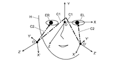
- the X axis, the Y axis, and the Z axis, and the X ′ axis, the Y ′ axis, and the Z ′ axis are defined as follows.
- an intermediate position between the left eye EL and the right eye ER of the user H is set as an origin O, and an axis forward from the origin O when viewed from the user H is a Z axis.
- An axis that is upward when viewed from the user H in the direction orthogonal to the Z axis is the Y axis
- an axis that is left outward from the user H is the X axis It is determined.
- the intersection point between the optical axis C1 of the light beam emitted from the projection optical system 12 (12L, 12R) and reaching the visor 10 and the reflection surface 10a of the visor 10 is an intersection point O ′, and the visor 10 at the intersection point O ′.
- the axis that is in the normal direction and viewed outward from the user H is the Z ′ axis, the direction orthogonal to the Z ′ axis and the optical axis C 1 of the light beam before being reflected by the visor 10 and the light beam after being reflected.
- An axis such that the optical axis C2 is on the Y′-Z ′ plane is defined as the Y ′ axis, and an axis orthogonal to both the Y ′ axis and the Z ′ axis is defined as the X ′ axis. Since the intersection point O ′ exists corresponding to the left eye EL and the right eye ER, as shown in FIG. 4, the X ′ axis, the Y ′ axis, and the Z ′ axis also exist on the left and right sides, respectively.
- the reflective surface 100a of the visor 100 is spherical, whereas in the HMD of this embodiment, the reflective surface 10a of the visor 10 is rotationally symmetric expressed by the following equation (1). It has an aspherical shape (axisymmetric aspherical shape), and its apex U exists on the YZ plane. Since it has an aspherical shape, the curvature in the Y′-axis direction and the curvature in the X′-axis direction at the intersection O ′ are different. As will be described later, the former is smaller than the latter (that is, the curvature in the Y′-axis direction). The radius is set larger than the radius of curvature in the X′-axis direction).
- the visor 10 is attached to a helmet (not shown) so as to be rotatable around the X axis.
- a helmet not shown
- the reflective surface 10 a is inclined so that the upper side thereof falls forward in front of the eyes of the user H. It is in a state.
- the inclination angle at the intersection point O ′ (the angle between the tangent plane of the reflecting surface 10a and the plane upright at the intersection point O ′) is 10 ° or more.
- the image display unit 11 includes a transmissive display element 112 such as a transmissive color liquid crystal display element and a backlight illumination unit 111, and light emitted from the backlight illumination unit 111 is transmitted through the transmissive display element.
- a transmissive display element 112 such as a transmissive color liquid crystal display element and a backlight illumination unit 111
- light emitted from the backlight illumination unit 111 is transmitted through the transmissive display element.
- an image formed on the display surface of the transmissive display element 112 is emitted as display light. This is completely symmetrical (that is, plane symmetry with respect to the YZ plane).
- the projection optical system 12 includes a plurality of lenses 121, a back surface reflection type mirror 122 having a concave reflection surface, and a flat plate mirror 123.
- the lens 121 and the back reflection mirror 122 are provided independently on the left and right, whereas the flat mirror 123 is arranged so as to cross the YZ plane perpendicularly.
- the left and right projection optical systems 12L and 12R are shared.
- the display light emitted from the image display unit 11 passes through a lens (two lenses are used in FIG. 2, but the number is not limited) and reaches the back surface reflection type mirror 122, but is incident on the back surface reflection type mirror 122. After being refracted by the side refracting surface 122a, it reaches the reflecting surface 122b and is reflected while being condensed by the reflecting surface 122b. The reflected light is reflected again by the mirror 123 and travels toward the reflective surface 10a of the visor 10. However, since the reflected light is collected by the reflective surface 122b of the back surface reflection type mirror 122, the reflected light is reflected between the mirror 123 and the reflective surface 10a. An intermediate image is once formed on the optical path. In FIG.
- the image plane on which the intermediate image is formed is indicated by the symbol Q.
- an intermediate image is formed both in the vertical direction (that is, in the plane parallel to the YZ plane) and in the horizontal direction (in the plane parallel to the XZ plane).
- the intermediate image may be formed inside the projection optical system 12 including the mirror 123, not on the optical path between the mirror 123 and the reflecting surface 10a.
- the optical axis of the display light emitted from the image display unit 11 and incident on the lens 121 of the projection optical system 12 is the transmission type display element 112 of the image display unit 11. It is not orthogonal to the display surface. That is, a configuration of a non-coaxial optical system is adopted. For this reason, a display image with asymmetric blur is formed. Therefore, the blur of the display image as described above is corrected by making the refractive surface 122a and the reflecting surface 122b of the back surface reflection type mirror 122 or at least one of the lenses 121 aspherical.
- the display light emitted from the projection optical system 12 strictly speaking, the display light that gradually spreads from the image plane Q of the intermediate image hits the reflection surface 10 a of the visor 10 and is condensed on the concave surface. Reflected. At this time, the incident angle of the optical axis of the incident light in the Y′-Z ′ plane is not the same as the incident angle of the optical axis of the incident light in the X′-Z ′ plane. If it is spherical, a difference occurs in the optical power in both planes, causing astigmatism.
- the curvature in the Y′-Z ′ plane is more than the curvature in the X′-Z ′ plane by the amount corresponding to the difference in the incident angle of the optical axis of the incident light.
- the optical power in both planes is made almost the same. In practice, this difference in curvature is slight.
- both the radii of curvature are in the range of 50 to 500 mm.
- the shape of the reflective surface 10a of the visor 10 is an aspherical shape, it is not limited to the rotationally symmetric aspherical shape having the point U as a vertex as described above.
- a toroidal surface shape defined by the following equation (2) may be used.
- it may be a free-form surface shape that is defined by the following equation (3) and is plane-symmetric with respect to the Y ′ axis corresponding to both eyes EL and ER.
- the configurations of the image display unit 11 and the projection optical system 12 can be changed as appropriate.
- 5 to 7 are schematic diagrams showing examples of different configurations of the display unit.
- the image display unit 11A shown in FIG. 5 includes an illumination unit 11A1, a reflective display element 11A2 such as a reflective color liquid crystal display element, and a reflective optical element 11A3 including a beam splitter.
- the light emitted from the illumination unit 11A1 is reflected by the reflective optical element 11A3 and travels toward the reflective display element 11A2. Then, the image information formed on the display surface when it is reflected by the display surface of the reflective display element 11A2 is received and emitted as display light through the reflective display element 11A3 to the outside.
- a self-luminous display element 11B1 such as an organic EL display.
- the display element 11B1 itself emits light and emits display light, it is not necessary to separately provide an illumination unit.
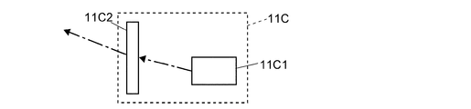
- the image display unit 11C shown in FIG. 7 includes a small projector 11C1 and a small screen 11C2.
- the display light emitted from the small projector 11C1 is projected onto the small screen 11C2, and an enlarged display image is formed on the small screen 11C2.
- the display image on the small screen 11C2 is emitted as display light as it is.
- a monochrome display element is used as the display element 112
- a color projector or a small projector that emits light of two or more colors is used for the backlight illumination unit 111.
- a display image of two or more colors can be formed.
- HMD Helmet mount display
- SYMBOLS 10 ... Visor 10a ... Reflective action surface 10a ... Reflective surface 11, 11A, 11B, 11C, 11L, 11R ... Image display part 111 ... Backlight illumination part 112 ... Transmission type display element 12, 12L, 12R ... Projection optical system 121 ... Lens 122 ... Back-reflecting mirror 122a ... Refraction surface 122b ... Reflecting surface 123 ... Flat mirror C1 ... Optical axis C2 of incident light beam ... Optical axis EL of outgoing light beam ... Left eye ER ... Right eye H ... User
Landscapes
- Physics & Mathematics (AREA)
- General Physics & Mathematics (AREA)
- Optics & Photonics (AREA)
- Engineering & Computer Science (AREA)
- Multimedia (AREA)
- Signal Processing (AREA)
- Testing, Inspecting, Measuring Of Stereoscopic Televisions And Televisions (AREA)
Abstract
Description
断面が円形の一部を切り取った形状である球形状のバイザ100は、使用者Hの頭部を被う一方、使用者Hの顔面前方が開放された形状である図示しないヘルメットに上下にスライド可能な状態で取り付けられている。バイザ100は使用者Hに向いた内面が反射面100aであり、該反射面100aには、表示光の一部を反射するとともに、外界から到来する光の一部を透過する被覆層が形成されている。
水平前方を向いた使用者の左右両眼の間の中央の位置を原点O、使用者から見て原点Oから前方に向かう軸をZ軸、Z軸に対し直交し使用者から見て上方向に向かう軸をY軸、Z軸及びY軸に共に直交する軸をX軸として定義するとともに、前記バイザの反射作用面への入射光線の光軸と該反射作用面との交点をO’、該反射作用面における前記交点O’での法線をZ’軸、該Z’軸に直交し、且つ、前記入射光線の光軸と該入射光線に対し前記反射作用面で反射して使用者の眼に向かって進行する出射光線の光軸とが含まれる平面をZ’軸とでなす軸をY’軸、Y’軸及びZ’軸に共に直交する軸をX’軸、として定義したとき、
前記投射光学系の内部、又は該投射光学系と前記反射作用面との間の光路上において中間像が形成され、
前記バイザは、前記ヘルメットに対しX軸に平行な軸を中心に回転可能であり、上方へスライドすることで使用者が前記ヘルメットを着脱することを可能とする一方、当該バイザの使用時には使用者の眼前でその反射作用面の上側が外方に倒れるように傾斜した状態に保持され、
該バイザの反射作用面の形状は、Y’-Z’平面内の曲率がX’-Z’平面影面内の曲率よりも小さな非球面形状であることを特徴としている。
本発明に係る頭部装着型表示装置の一実施態様として、前記バイザの反射作用面は自由曲面形状であり、使用者の両眼にそれぞれ対応したY’軸に対し面対称形状である構成とすることができる。
これにより、バイザ自体の基材の種類や厚さに依らずに、適切な反射及び外光の透過を実現可能な反射作用面を形成することができる。
これにより、バイザ自体の基材の種類や厚さに依らずに、反射を低減しゴースト像を抑制可能な反射低減面を形成することができる。
なお、この構成において、前記レンズは屈折率ndが1.58以上であるものとするとよい。
このように屈折率が高いレンズを用いることにより、光学的パワーが増加し、レンズ枚数を少なくすることができ、重量、サイズ、コスト等を低減することができる。
この構成によれば、例えば、一般的な情報の表示と緊急を要する情報の表示とを異なる色として、より的確に情報を使用者に伝えることができる。
例えば本発明に係る頭部装着型表示装置の一実施態様として、前記表示部は、透過型の表示素子、及び、該表示素子に背面側から照明光を照射するバックライト照明部、を含む構成とすることができる。
図1は本実施例のHMDのバイザを含む光学系の概略構成図であり、(a)は概略縦断面図、(b)は概略横断面図である。また、図2及び図3はそれぞれ図1(a)及び(b)において、光学系の構成をより詳細に示した図である。また、図4は表示光の概略光路を示す斜視図である。図4ではバイザ等の記載を省略している。
図1、図4中に示すように、使用者Hの左眼EL及び右眼ERの中間の位置を原点Oとし、使用者Hから見てその原点Oから前方へ向かう軸をZ軸、該Z軸に直交する方向で使用者Hから見て上方向となる軸をY軸、Y軸及びZ軸の両方に直交する軸で使用者Hから見て左外方となる軸をX軸、と定める。また、投射光学系12(12L、12R)から出射してバイザ10に到達するまでの光線の光軸C1とバイザ10の反射面10aとの交点を交点O’、その交点O’におけるバイザ10の法線方向で使用者Hから見て外方向に向かう軸をZ’軸、該Z’軸に直交する方向であってバイザ10で反射する前の光線の光軸C1と反射したあとの光線の光軸C2とが共にY’-Z’平面上に存在するような軸をY’軸、Y’軸及びZ’軸の両方に直交する軸をX’軸と定める。なお、交点O’は左眼EL、右眼ERに対応してそれぞれ存在するから、図4に示すように、X’軸、Y’軸、Z’軸も左右それぞれ存在する。

バイザ10は図示しないヘルメットに対してX軸周りに回転可能に取り付けられている。図1(a)及び図2に示すように、バイザ10が完全におろされた状態(つまりは使用状態)では、使用者Hの眼前において反射面10aはその上部側が前方に倒れるように傾斜した状態となっている。交点O’におけるその傾斜角(交点O’における反射面10aの接平面と直立する平面とのなす角度)は10°以上である。


図5~図7はそれぞれ、表示部について異なる構成の例を示す概略図である。
10…バイザ
10a…反射作用面
10a…反射面
11、11A、11B、11C、11L、11R…画像表示部
111…バックライト照明部
112…透過型表示素子
12、12L、12R…投射光学系
121…レンズ
122…裏面反射型ミラー
122a…屈折面
122b…反射面
123…平板状ミラー
C1…入射光束の光軸
C2…出射光束の光軸
EL…左眼
ER…右眼
H…使用者
Claims (22)
- 使用者が頭部に装着するヘルメットと、該ヘルメットに取り付けられ、使用者の眼前に配置される外方に膨出した曲面状のバイザと、表示画像を形成する表示部と、該表示部による表示画像を情報として含む表示光を前記バイザの反射作用面に投影する投射光学系と、を具備し、前記バイザを通して視認される外界の光景に前記表示画像による虚像を形成する頭部装着型表示装置であって、
水平前方を向いた使用者の左右両眼の間の中央の位置を原点O、使用者から見て原点Oから前方に向かう軸をZ軸、Z軸に対し直交し使用者から見て上方向に向かう軸をY軸、Z軸及びY軸に共に直交する軸をX軸として定義するとともに、前記バイザの反射作用面への入射光線の光軸と該反射作用面との交点をO’、該反射作用面における前記交点O’での法線をZ’軸、該Z’軸に直交し、且つ、前記入射光線の光軸と該入射光線に対し前記反射作用面で反射して使用者の眼に向かって進行する出射光線の光軸とが含まれる平面をZ’軸とでなす軸をY’軸、Y’軸及びZ’軸に共に直交する軸をX’軸、として定義したとき、
前記投射光学系の内部、又は該投射光学系と前記反射作用面との間の光路上において中間像が形成され、
前記バイザは、前記ヘルメットに対しX軸に平行な軸を中心に回転可能であり、上方へスライドすることで使用者が前記ヘルメットを着脱することを可能とする一方、当該バイザの使用時には使用者の眼前でその反射作用面の上側が外方に倒れるように傾斜した状態に保持され、
該バイザの反射作用面の形状は、Y’-Z’平面内の曲率がX’-Z’平面影面内の曲率よりも小さな非球面形状であることを特徴とする頭部装着型表示装置。 - 請求項1に記載の頭部装着型表示装置であって、
前記バイザの反射作用面の形状は、該反射作用面に対する表示光の入射角の相違による光学的パワーの差異に相当する分だけY’-Z’平面内の曲率がX’-Z’平面内の曲率よりも小さな非球面形状であることを特徴とする頭部装着型表示装置。 - 請求項1に記載の頭部装着型表示装置であって、
前記バイザの反射作用面は自由曲面形状であり、使用者の両眼にそれぞれ対応したY’軸に対し面対称形状であることを特徴とする頭部装着型表示装置。 - 請求項1に記載の頭部装着型表示装置であって、
前記バイザの反射作用面は、Z-Y平面上に位置する頂点に対し回転対称である非球面形状であることを特徴とする頭部装着型表示装置。 - 請求項1に記載の頭部装着型表示装置であって、
前記バイザの反射作用面は、Y’-Z’平面内とX’-Z’平面内とで曲率が互いに相違するトロイダル面形状であることを特徴とする頭部装着型表示装置。 - 請求項1に記載の頭部装着型表示装置であって、
交点O’における前記反射作用面の傾斜角は10°以上であり、該反射作用面のY’-Z’平面内とX’-Z’平面内とでの曲率半径は共に50~500mmの範囲内であり、該バイザの厚さは0.1~10mmの範囲内であることを特徴とする頭部装着型表示装置。 - 請求項6に記載の頭部装着型表示装置であって、
前記バイザは、その内面又は外面に該バイザの基材と異なる材料による表面層が形成されていることを特徴とする頭部装着型表示装置。 - 請求項1に記載の頭部装着型表示装置であって、
前記投射光学系は少なくとも1枚の反射鏡を含み、該反射鏡の反射作用面は非球面形状であることを特徴とする頭部装着型表示装置。 - 請求項8に記載の頭部装着型表示装置であって、
前記反射鏡の反射作用面は凹面であることを特徴とする頭部装着型表示装置。 - 請求項9に記載の頭部装着型表示装置であって、
前記反射鏡は裏面反射鏡であり、反射作用に加えて屈折作用も有することを特徴とする頭部装着型表示装置。 - 請求項10に記載の頭部装着型表示装置であって、
前記屈折作用を有する面は非球面形状であることを特徴とする頭部装着型表示装置。 - 請求項1に記載の頭部装着型表示装置であって、
前記投射光学系は両面に屈性作用を有するレンズを少なくとも1枚含み、該レンズの少なくとも一面は非球面形状であることを特徴とする頭部装着型表示装置。 - 請求項12に記載の頭部装着型表示装置であって、
前記レンズは屈折率ndが1.58以上であることを特徴とする頭部装着型表示装置。 - 請求項1に記載の頭部装着型表示装置であって、
前記表示部は二色以上の表示を行うものであることを特徴とする頭部装着型表示装置。 - 請求項1に記載の頭部装着型表示装置であって、
前記表示部から出射される表示光の視野中心となる主光線は、該表示部の表示面に対し非直交方向の角度で出射するように該表示部及び前記投射光学系が配置されていることを特徴とする頭部装着型表示装置。 - 請求項1に記載の頭部装着型表示装置であって、
前記表示部から出射される表示光の視野中心となる主光線は、該表示部の表示面の中心を外れた位置から出射するように該表示部及び前記投射光学系が配置されていることを特徴とする頭部装着型表示装置。 - 請求項1に記載の頭部装着型表示装置であって、
前記表示部は、透過型の表示素子、及び、該表示素子に背面側から照明光を照射するバックライト照明部、を含んで構成されていることを特徴とする頭部装着型表示装置。 - 請求項1に記載の頭部装着型表示装置であって、
前記表示部は、反射型の表示素子、照明光を出射する照明部、及び、前記照明光を前記表示素子の表示面側に照射するとともに該表示面で反射した光を案内する反射型光学系と、を含んで構成されていることを特徴とする頭部装着型表示装置。 - 請求項1に記載の頭部装着型表示装置であって、
前記表示部は、自発光型の表示素子を含むことを特徴とする頭部装着型表示装置。 - 請求項1に記載の頭部装着型表示装置であって、
前記表示部は、小型プロジェクタ及び小型スクリーンを含むことを特徴とする頭部装着型表示装置。 - 請求項14に記載の頭部装着型表示装置であって、
前記表示部は、透過型の表示素子、及び、該表示素子に背面側から照明光を照射するものであって少なくとも一部が小型プロジェクタであるバックライト照明部、を含むことを特徴とする頭部装着型表示装置。 - 請求項1に記載の頭部装着型表示装置であって、
前記表示部及び前記投射光学系は使用者の両眼に対応して左右一対設けられ、該左右の投射光学系を構成する光学素子の一部は両眼に共通に利用されていることを特徴とする頭部装着型表示装置。
Priority Applications (5)
| Application Number | Priority Date | Filing Date | Title |
|---|---|---|---|
| JP2019519909A JP6841326B2 (ja) | 2017-05-25 | 2017-05-25 | 頭部装着型表示装置 |
| US16/615,533 US20200186759A1 (en) | 2017-05-25 | 2017-05-25 | Head mounted display device |
| PCT/JP2017/019590 WO2018216176A1 (ja) | 2017-05-25 | 2017-05-25 | 頭部装着型表示装置 |
| EP17911344.4A EP3633435B1 (en) | 2017-05-25 | 2017-05-25 | Head-mounted display device |
| TW107109498A TWI681211B (zh) | 2017-05-25 | 2018-03-20 | 頭戴式顯示裝置 |
Applications Claiming Priority (1)
| Application Number | Priority Date | Filing Date | Title |
|---|---|---|---|
| PCT/JP2017/019590 WO2018216176A1 (ja) | 2017-05-25 | 2017-05-25 | 頭部装着型表示装置 |
Publications (1)
| Publication Number | Publication Date |
|---|---|
| WO2018216176A1 true WO2018216176A1 (ja) | 2018-11-29 |
Family
ID=64396440
Family Applications (1)
| Application Number | Title | Priority Date | Filing Date |
|---|---|---|---|
| PCT/JP2017/019590 Ceased WO2018216176A1 (ja) | 2017-05-25 | 2017-05-25 | 頭部装着型表示装置 |
Country Status (5)
| Country | Link |
|---|---|
| US (1) | US20200186759A1 (ja) |
| EP (1) | EP3633435B1 (ja) |
| JP (1) | JP6841326B2 (ja) |
| TW (1) | TWI681211B (ja) |
| WO (1) | WO2018216176A1 (ja) |
Families Citing this family (1)
| Publication number | Priority date | Publication date | Assignee | Title |
|---|---|---|---|---|
| US11119570B1 (en) * | 2020-10-29 | 2021-09-14 | XRSpace CO., LTD. | Method and system of modifying position of cursor |
Citations (7)
| Publication number | Priority date | Publication date | Assignee | Title |
|---|---|---|---|---|
| JPS61501946A (ja) * | 1984-04-16 | 1986-09-04 | ヒユ−ズ・エアクラフト・カンパニ− | ホログラフィックヘルメットに装着した両眼用ディスプレイ |
| JPH07218859A (ja) * | 1994-02-07 | 1995-08-18 | Olympus Optical Co Ltd | 映像表示装置 |
| US5722091A (en) * | 1994-11-04 | 1998-03-03 | Intertechnique | Protective equipment for the pilot of a military aircraft, and a method of personalizing the equipment |
| JP2002542409A (ja) * | 1999-04-16 | 2002-12-10 | タレス アヴィオニックス エス.アー. | ヘルメット用バイザー |
| JP2010019874A (ja) | 2008-07-08 | 2010-01-28 | Shimadzu Corp | 表示装置 |
| JP2013178422A (ja) * | 2012-02-29 | 2013-09-09 | Nippon Seiki Co Ltd | ヘッドアップディスプレイ装置 |
| JP2015154420A (ja) | 2014-02-18 | 2015-08-24 | 株式会社島津製作所 | 表示装置 |
Family Cites Families (12)
| Publication number | Priority date | Publication date | Assignee | Title |
|---|---|---|---|---|
| US5035474A (en) * | 1984-04-16 | 1991-07-30 | Hughes Aircraft Company | Biocular holographic helmet mounted display |
| US4897715A (en) * | 1988-10-31 | 1990-01-30 | General Electric Company | Helmet display |
| GB9213603D0 (en) * | 1992-06-26 | 1992-10-07 | Marconi Gec Ltd | Helmet mounted display systems |
| US5309169A (en) * | 1993-02-01 | 1994-05-03 | Honeywell Inc. | Visor display with fiber optic faceplate correction |
| TWI294528B (en) * | 2002-11-19 | 2008-03-11 | Headplay Barbados Inc | System and method for channeling images within a head mounted display |
| JPWO2010061835A1 (ja) * | 2008-11-26 | 2012-04-26 | コニカミノルタオプト株式会社 | 映像表示装置およびヘッドマウントディスプレイ |
| ES2929791T3 (es) * | 2009-04-29 | 2022-12-01 | Bae Systems Plc | Visualizador montado en la cabeza |
| JP6464708B2 (ja) * | 2014-12-08 | 2019-02-06 | セイコーエプソン株式会社 | 画像表示装置 |
| US9977245B2 (en) * | 2015-02-27 | 2018-05-22 | LAFORGE Optical, Inc. | Augmented reality eyewear |
| GB201508006D0 (en) * | 2015-05-11 | 2015-06-24 | The Technology Partnership Plc | Optical system for a display with an off axis projector |
| US20180067317A1 (en) * | 2016-09-06 | 2018-03-08 | Allomind, Inc. | Head mounted display with reduced thickness using a single axis optical system |
| IL248845B (en) * | 2016-11-08 | 2018-03-29 | Elbit Systems Ltd | Fault-tolerant display |
-
2017
- 2017-05-25 JP JP2019519909A patent/JP6841326B2/ja active Active
- 2017-05-25 WO PCT/JP2017/019590 patent/WO2018216176A1/ja not_active Ceased
- 2017-05-25 EP EP17911344.4A patent/EP3633435B1/en active Active
- 2017-05-25 US US16/615,533 patent/US20200186759A1/en not_active Abandoned
-
2018
- 2018-03-20 TW TW107109498A patent/TWI681211B/zh not_active IP Right Cessation
Patent Citations (7)
| Publication number | Priority date | Publication date | Assignee | Title |
|---|---|---|---|---|
| JPS61501946A (ja) * | 1984-04-16 | 1986-09-04 | ヒユ−ズ・エアクラフト・カンパニ− | ホログラフィックヘルメットに装着した両眼用ディスプレイ |
| JPH07218859A (ja) * | 1994-02-07 | 1995-08-18 | Olympus Optical Co Ltd | 映像表示装置 |
| US5722091A (en) * | 1994-11-04 | 1998-03-03 | Intertechnique | Protective equipment for the pilot of a military aircraft, and a method of personalizing the equipment |
| JP2002542409A (ja) * | 1999-04-16 | 2002-12-10 | タレス アヴィオニックス エス.アー. | ヘルメット用バイザー |
| JP2010019874A (ja) | 2008-07-08 | 2010-01-28 | Shimadzu Corp | 表示装置 |
| JP2013178422A (ja) * | 2012-02-29 | 2013-09-09 | Nippon Seiki Co Ltd | ヘッドアップディスプレイ装置 |
| JP2015154420A (ja) | 2014-02-18 | 2015-08-24 | 株式会社島津製作所 | 表示装置 |
Non-Patent Citations (1)
| Title |
|---|
| See also references of EP3633435A4 |
Also Published As
| Publication number | Publication date |
|---|---|
| TWI681211B (zh) | 2020-01-01 |
| US20200186759A1 (en) | 2020-06-11 |
| EP3633435A1 (en) | 2020-04-08 |
| JP6841326B2 (ja) | 2021-03-10 |
| JPWO2018216176A1 (ja) | 2020-01-09 |
| TW201901242A (zh) | 2019-01-01 |
| EP3633435A4 (en) | 2020-07-08 |
| EP3633435B1 (en) | 2022-12-21 |
Similar Documents
| Publication | Publication Date | Title |
|---|---|---|
| JP5290092B2 (ja) | 眼鏡型画像表示装置 | |
| JP6065630B2 (ja) | 虚像表示装置 | |
| JP6065631B2 (ja) | 虚像表示装置 | |
| JP6369017B2 (ja) | 虚像表示装置 | |
| JP6641987B2 (ja) | 虚像表示装置 | |
| JP6221732B2 (ja) | 虚像表示装置 | |
| JP6111635B2 (ja) | 虚像表示装置 | |
| JP6595619B2 (ja) | シースルーヘッドウェアラブルディスプレイのための効率的な薄い湾曲したアイピース | |
| JP6221731B2 (ja) | 虚像表示装置 | |
| WO2019082540A1 (ja) | 頭部装着型表示装置 | |
| JP6111636B2 (ja) | 虚像表示装置 | |
| JP5290091B2 (ja) | 眼鏡型画像表示装置 | |
| WO2015033534A1 (en) | Virtual image display apparatus | |
| JP6020113B2 (ja) | 虚像表示装置 | |
| JP6697455B2 (ja) | 交差光学系を含む頭部装着ビューイングシステム | |
| JP6819221B2 (ja) | 虚像表示装置 | |
| CN106707531A (zh) | 一种显示装置及穿戴式设备 | |
| US11099395B2 (en) | Virtual image display device | |
| TWI681211B (zh) | 頭戴式顯示裝置 | |
| JP6417657B2 (ja) | 虚像表示装置 | |
| JP2019179083A (ja) | 画像表示装置 | |
| JP6955388B2 (ja) | 画像表示装置 | |
| CN121666548A (zh) | 光学系统和显示装置 | |
| JP2018169501A (ja) | 観察光学系および画像観察装置 |
Legal Events
| Date | Code | Title | Description |
|---|---|---|---|
| 121 | Ep: the epo has been informed by wipo that ep was designated in this application |
Ref document number: 17911344 Country of ref document: EP Kind code of ref document: A1 |
|
| ENP | Entry into the national phase |
Ref document number: 2019519909 Country of ref document: JP Kind code of ref document: A |
|
| NENP | Non-entry into the national phase |
Ref country code: DE |
|
| WWE | Wipo information: entry into national phase |
Ref document number: 2017911344 Country of ref document: EP |
|
| ENP | Entry into the national phase |
Ref document number: 2017911344 Country of ref document: EP Effective date: 20200102 |