WO2018225172A1 - 自走式掃除機 - Google Patents
自走式掃除機 Download PDFInfo
- Publication number
- WO2018225172A1 WO2018225172A1 PCT/JP2017/021101 JP2017021101W WO2018225172A1 WO 2018225172 A1 WO2018225172 A1 WO 2018225172A1 JP 2017021101 W JP2017021101 W JP 2017021101W WO 2018225172 A1 WO2018225172 A1 WO 2018225172A1
- Authority
- WO
- WIPO (PCT)
- Prior art keywords
- unit
- self
- cleaner
- propelled
- detection
- Prior art date
- Legal status (The legal status is an assumption and is not a legal conclusion. Google has not performed a legal analysis and makes no representation as to the accuracy of the status listed.)
- Ceased
Links
Images







Classifications
-
- A—HUMAN NECESSITIES
- A47—FURNITURE; DOMESTIC ARTICLES OR APPLIANCES; COFFEE MILLS; SPICE MILLS; SUCTION CLEANERS IN GENERAL
- A47L—DOMESTIC WASHING OR CLEANING; SUCTION CLEANERS IN GENERAL
- A47L9/00—Details or accessories of suction cleaners, e.g. mechanical means for controlling the suction or for effecting pulsating action; Storing devices specially adapted to suction cleaners or parts thereof; Carrying-vehicles specially adapted for suction cleaners
- A47L9/28—Installation of the electric equipment, e.g. adaptation or attachment to the suction cleaner; Controlling suction cleaners by electric means
- A47L9/2805—Parameters or conditions being sensed
-
- A—HUMAN NECESSITIES
- A47—FURNITURE; DOMESTIC ARTICLES OR APPLIANCES; COFFEE MILLS; SPICE MILLS; SUCTION CLEANERS IN GENERAL
- A47L—DOMESTIC WASHING OR CLEANING; SUCTION CLEANERS IN GENERAL
- A47L11/00—Machines for cleaning floors, carpets, furniture, walls, or wall coverings
- A47L11/40—Parts or details of machines not provided for in groups A47L11/02 - A47L11/38, or not restricted to one of these groups, e.g. handles, arrangements of switches, skirts, buffers, levers
- A47L11/4061—Steering means; Means for avoiding obstacles; Details related to the place where the driver is accommodated
-
- A—HUMAN NECESSITIES
- A47—FURNITURE; DOMESTIC ARTICLES OR APPLIANCES; COFFEE MILLS; SPICE MILLS; SUCTION CLEANERS IN GENERAL
- A47L—DOMESTIC WASHING OR CLEANING; SUCTION CLEANERS IN GENERAL
- A47L11/00—Machines for cleaning floors, carpets, furniture, walls, or wall coverings
- A47L11/40—Parts or details of machines not provided for in groups A47L11/02 - A47L11/38, or not restricted to one of these groups, e.g. handles, arrangements of switches, skirts, buffers, levers
- A47L11/4011—Regulation of the cleaning machine by electric means; Control systems and remote control systems therefor
-
- A—HUMAN NECESSITIES
- A47—FURNITURE; DOMESTIC ARTICLES OR APPLIANCES; COFFEE MILLS; SPICE MILLS; SUCTION CLEANERS IN GENERAL
- A47L—DOMESTIC WASHING OR CLEANING; SUCTION CLEANERS IN GENERAL
- A47L11/00—Machines for cleaning floors, carpets, furniture, walls, or wall coverings
- A47L11/40—Parts or details of machines not provided for in groups A47L11/02 - A47L11/38, or not restricted to one of these groups, e.g. handles, arrangements of switches, skirts, buffers, levers
- A47L11/4063—Driving means; Transmission means therefor
- A47L11/4066—Propulsion of the whole machine
-
- A—HUMAN NECESSITIES
- A47—FURNITURE; DOMESTIC ARTICLES OR APPLIANCES; COFFEE MILLS; SPICE MILLS; SUCTION CLEANERS IN GENERAL
- A47L—DOMESTIC WASHING OR CLEANING; SUCTION CLEANERS IN GENERAL
- A47L9/00—Details or accessories of suction cleaners, e.g. mechanical means for controlling the suction or for effecting pulsating action; Storing devices specially adapted to suction cleaners or parts thereof; Carrying-vehicles specially adapted for suction cleaners
- A47L9/009—Carrying-vehicles; Arrangements of trollies or wheels; Means for avoiding mechanical obstacles
-
- A—HUMAN NECESSITIES
- A47—FURNITURE; DOMESTIC ARTICLES OR APPLIANCES; COFFEE MILLS; SPICE MILLS; SUCTION CLEANERS IN GENERAL
- A47L—DOMESTIC WASHING OR CLEANING; SUCTION CLEANERS IN GENERAL
- A47L9/00—Details or accessories of suction cleaners, e.g. mechanical means for controlling the suction or for effecting pulsating action; Storing devices specially adapted to suction cleaners or parts thereof; Carrying-vehicles specially adapted for suction cleaners
- A47L9/28—Installation of the electric equipment, e.g. adaptation or attachment to the suction cleaner; Controlling suction cleaners by electric means
-
- A—HUMAN NECESSITIES
- A47—FURNITURE; DOMESTIC ARTICLES OR APPLIANCES; COFFEE MILLS; SPICE MILLS; SUCTION CLEANERS IN GENERAL
- A47L—DOMESTIC WASHING OR CLEANING; SUCTION CLEANERS IN GENERAL
- A47L9/00—Details or accessories of suction cleaners, e.g. mechanical means for controlling the suction or for effecting pulsating action; Storing devices specially adapted to suction cleaners or parts thereof; Carrying-vehicles specially adapted for suction cleaners
- A47L9/28—Installation of the electric equipment, e.g. adaptation or attachment to the suction cleaner; Controlling suction cleaners by electric means
- A47L9/2805—Parameters or conditions being sensed
- A47L9/2826—Parameters or conditions being sensed the condition of the floor
-
- A—HUMAN NECESSITIES
- A47—FURNITURE; DOMESTIC ARTICLES OR APPLIANCES; COFFEE MILLS; SPICE MILLS; SUCTION CLEANERS IN GENERAL
- A47L—DOMESTIC WASHING OR CLEANING; SUCTION CLEANERS IN GENERAL
- A47L9/00—Details or accessories of suction cleaners, e.g. mechanical means for controlling the suction or for effecting pulsating action; Storing devices specially adapted to suction cleaners or parts thereof; Carrying-vehicles specially adapted for suction cleaners
- A47L9/28—Installation of the electric equipment, e.g. adaptation or attachment to the suction cleaner; Controlling suction cleaners by electric means
- A47L9/2836—Installation of the electric equipment, e.g. adaptation or attachment to the suction cleaner; Controlling suction cleaners by electric means characterised by the parts which are controlled
- A47L9/2852—Elements for displacement of the vacuum cleaner or the accessories therefor, e.g. wheels, casters or nozzles
-
- A—HUMAN NECESSITIES
- A47—FURNITURE; DOMESTIC ARTICLES OR APPLIANCES; COFFEE MILLS; SPICE MILLS; SUCTION CLEANERS IN GENERAL
- A47L—DOMESTIC WASHING OR CLEANING; SUCTION CLEANERS IN GENERAL
- A47L9/00—Details or accessories of suction cleaners, e.g. mechanical means for controlling the suction or for effecting pulsating action; Storing devices specially adapted to suction cleaners or parts thereof; Carrying-vehicles specially adapted for suction cleaners
- A47L9/28—Installation of the electric equipment, e.g. adaptation or attachment to the suction cleaner; Controlling suction cleaners by electric means
- A47L9/2857—User input or output elements for control, e.g. buttons, switches or displays
-
- A—HUMAN NECESSITIES
- A47—FURNITURE; DOMESTIC ARTICLES OR APPLIANCES; COFFEE MILLS; SPICE MILLS; SUCTION CLEANERS IN GENERAL
- A47L—DOMESTIC WASHING OR CLEANING; SUCTION CLEANERS IN GENERAL
- A47L2201/00—Robotic cleaning machines, i.e. with automatic control of the travelling movement or the cleaning operation
- A47L2201/04—Automatic control of the travelling movement; Automatic obstacle detection
Definitions
- the present invention relates to a self-propelled cleaner.
- the traveling means includes a pair of left and right wheels and two motors that drive the wheels in the forward direction and the reverse direction, and causes the cleaner body to travel in the front-rear direction and to rotate in any direction.
- the suction means includes a duct and a blower communicated with the suction port, and a rotating brush provided at the suction port, and is configured to suck dust and the like scraped up by the rotating brush from the suction port.
- Such a general self-propelled cleaner is programmed to clean while self-propelled according to a preset travel map. Further, when it is detected by a contact sensor that an obstacle such as a wall or furniture has been touched, the traveling direction is changed to avoid the obstacle and then the route of the traveling map is returned.
- An object of the present invention is to provide a self-propelled cleaner capable of efficiently performing an obstacle avoidance operation and shortening a cleaning time.
- the self-propelled cleaner of the present invention is a self-propelled cleaner that can be cleaned while traveling along the floor surface, and has a cleaner body having wheels for self-propelling, and a travel drive that drives the wheels.
- a lifting / lowering unit that moves up and down the periphery detecting unit for detecting the periphery of the cleaner body, a projecting position above the cleaner body, and a housing position inside the cleaner body.
- the lift control unit drives the lift drive unit to raise and lower the periphery detection unit. It is characterized by making it.
- the periphery detection unit at the protruding position above the vacuum cleaner body can detect the periphery so that a wide range of obstacles can be detected. Accordingly, the travel control unit can control the travel drive unit to avoid obstacles. Therefore, the avoidance operation can be performed before contacting the obstacle, and the avoidance direction can be selected while recognizing the presence or absence of the obstacle in the avoidance direction, so that the avoidance operation is efficiently performed and the cleaning time is shortened. can do.
- the elevation control unit drives the elevation drive unit to raise and lower the periphery detection unit, so that the surrounding detection range can be changed, and obstacles can be detected more efficiently. Further, if the periphery detection unit is lowered, the periphery detection unit protruding upward does not get in the way and cleaning can be performed without narrowing the cleaning area.
- the elevating control unit lowers the periphery detecting unit to a position avoiding the obstacle when the periphery detecting unit detects an obstacle above the main body of the cleaner.
- the obstacle when an obstacle above the cleaner body is detected and it is determined that the surrounding detection unit is likely to come into contact with the obstacle, the obstacle is detected by lowering the surrounding detection unit. You can get under the obstacles.
- a detected portion is provided inside the cleaner body, and the measurement value of the periphery detecting portion is calibrated by causing the periphery detecting portion in the housing position to detect the detected portion. Is preferred.
- the cleaner body may be provided with an opening that opens in a predetermined direction, and the periphery detection unit at the housing position may detect the predetermined direction of the cleaner body through the opening. preferable.
- the periphery detection unit in the storage position detects through the opening of the cleaner body, so that an obstacle in a predetermined direction can be detected even if the periphery detection unit is stored in the cleaner body. And avoidance operation can be performed.
- the elevating control unit transmits a message to the user by an elevating operation for elevating the periphery detecting unit.
- the state of the vacuum cleaner can be transmitted in an easy-to-understand manner by transmitting a message to the user by the raising / lowering operation of the periphery detection unit, and as a user-friendly information transmission means (user interface)
- a peripheral detection unit can be used.
- an external force detection unit that detects an external force acting on the periphery detection unit is further provided, and the operation of the cleaner body is switched based on detection of the external force by the external force detection unit.
- the external force detection unit detects an external force acting on the peripheral detection unit, and uses the peripheral detection unit as a switch or an operation button by switching the operation of the cleaner body based on the detection. Can do.
- an inclination driving unit that changes the inclination angle of the vacuum cleaner body with respect to the floor surface by moving the wheel up and down.
- the detection range by the peripheral detection unit can be changed according to the inclination angle by changing the inclination angle with respect to the floor surface of the cleaner body by moving the wheel up and down by the inclination driving unit.
- the vacuum cleaner body is tilted so that the periphery detection unit is facing forward and downward, it becomes easier to detect nearby obstacles on the front floor surface, and the vacuum cleaner body is mounted so that the periphery detection unit faces upward and forward. By tilting, it becomes easy to detect an obstacle above and the detection accuracy of the obstacle can be improved.
- the perspective view of the self-propelled cleaner concerning a 1st embodiment of the present invention.
- Sectional drawing which shows the state which the periphery detection part protruded in the said self-propelled cleaner
- Sectional drawing which shows the state which accommodated the periphery detection part in the said self-propelled cleaner.
- Functional block diagram showing a schematic configuration of the self-propelled cleaner (A), (B) is a perspective view which shows operation
- Sectional drawing which is a self-propelled cleaner which concerns on 2nd Embodiment of this invention, and shows the state from which the periphery detection part protruded Sectional drawing which shows the state which accommodated the periphery detection part in the said self-propelled cleaner.
- Functional block diagram showing a schematic configuration of the self-propelled cleaner (A), (B) is a perspective view which shows operation
- (A), (B) is sectional drawing which shows other operation
- FIG. 1 is a perspective view of the self-propelled cleaner according to the first embodiment of the present invention.
- the self-propelled cleaner 1 is a cleaning robot that cleans the floor surface F while traveling along the floor surface F, and includes a cleaner main body 2 having wheels 111 for self-propelling, And a sensor unit 3 having an LRF (Laser Range Finder) 20 which is a periphery detection unit for detecting the periphery of the cleaner body 2.
- LRF Laser Range Finder
- the cleaner body 2 includes an overall cylindrical body 10, a travel drive unit 11 that drives a pair of wheels 111 for self-running, a control unit 12 that drives and controls the travel drive unit 11, and the cleaner body 2.
- a main body operation unit 13 for operation and a suction unit 14 provided on the lower surface of the body 10 for sucking dust and dust on the floor surface F are provided.
- the body 10 has a disk-shaped upper surface 101 and a cylindrical side surface 102, and a chassis (not shown) is provided on the inner bottom surface.
- the sensor unit 3 includes an LRF 20, a cylindrical body 21 having an overall cylindrical shape and an upper surface portion, a lift driving unit 22 that moves the cylindrical body 21 up and down relative to the cleaner body 2, and the LRF 20 that rotates inside the cylindrical body 21.
- the LRF 20 is a laser distance meter that measures the distance by irradiating laser light such as an infrared laser, and calculates the distance to the obstacle from the time until the irradiated laser light hits the obstacle and is reflected back. It is.
- the cylindrical body 21 is provided with a window portion 211 that continuously transmits laser light and reflected light emitted from the LRF 20 in the circumferential direction.
- the body 10 is provided with a guide cylinder 103 that opens to the upper surface 101 and can accommodate the sensor unit 3, and a guide groove 104 that guides the cylinder 21 up and down is formed on the inner surface of the guide cylinder 103.
- an opening 105 is formed on the side surface 102 of the body 10 to transmit the laser light and reflected light emitted from the LRF 20.
- the opening 105 is provided in a predetermined range along the circumferential direction of the side surface 102 on the front side of the cleaner body 2 and is irradiated by the LRF 20 when the sensor unit 3 is accommodated in the cleaner body 2. Laser light and reflected light are transmitted, and the front side of the cleaner body 2 can be detected through the opening 105.
- the travel drive unit 11 includes a pair of left and right wheels 111 and a motor 112 that independently drives the pair of wheels 111 to rotate.
- An auxiliary wheel 113 is provided at the front of the body 10.
- the main body operation unit 13 is provided with a power ON / OFF button, a cleaning mode selection button, a stop button, a charge button, and the like.
- a duct, a blower, a dust collection chamber and an exhaust port are connected to the suction portion 14 so that the sucked dust and the like are collected by a filter of the dust collection chamber and the sucked air is exhausted from the exhaust port. It has become.
- FIGS. 2 and 3 are cross-sectional views of the vacuum cleaner, respectively.
- FIG. 2 is a cross-sectional view illustrating a state in which the periphery detection unit is protruded
- FIG. 3 is a cross-sectional view illustrating a state in which the periphery detection unit is accommodated.
- the sensor unit 3 includes a protruding position (FIG. 2) that protrudes above the cleaner body 2, and an accommodation position (FIG. 3) that is accommodated in the guide tube 103 of the cleaner body 2. , And can be moved up and down.
- a support plate 212 is provided at the bottom of the cylindrical body 21, and a plurality of protrusions 213 that are guided by the guide grooves 104 of the guide tube 103 are formed around the support plate 212. Therefore, the sensor unit 3 can move up and down along a vertical axis Z orthogonal to the upper surface 101 of the body 10 and cannot rotate in the rotation direction R along a plane parallel to the upper surface 101 of the body 10. It is supported by.
- the elevating drive unit 22 that elevates the sensor unit 3 is fixed to the body 10, an elevating motor 221 that is fixed inside the cylinder body 21, a plurality of elevating gears 222 that reduce the rotational speed of the output shaft of the elevating motor 221, and the body 10. And a rack 223 that meshes with the final gear of the elevating gear 222.
- the elevating drive unit 22 is configured to elevate the sensor unit 3 along the rack 223 by decelerating the rotation of the elevating motor 221 with the elevating gear 222 and transmitting it to the rack 223.
- the rotation drive unit 23 is connected to the rotation motor 231 fixed to the support plate 212 of the cylinder 21, the rotation gear 232 meshed with the output shaft of the rotation motor 231, and the rotation gear 232 so as to be perpendicular to the inside of the cylinder 21.
- a rotating body 233 rotatable around the axis Z, and the LRF 20 is fixed to the rotating body 233.
- the rotation drive unit 23 is configured to rotate the LRF 20 along the rotation direction R by transmitting the rotation of the rotation motor 231 from the rotation gear 232 to the rotating body 233.
- the upper sensor 24 is a distance sensor such as an ultrasonic sensor.
- the upper sensor 24 irradiates ultrasonic waves upward from the upper surface of the cylindrical body 21, and the obstacle from the time until the irradiated ultrasonic waves are reflected by the obstacle and returned. It functions as an upward detection means for calculating the distance to
- the upper sensor 24 is controlled to be turned ON / OFF by a command from the control unit 12 and detects an obstacle above the sensor unit 3 when turned ON. Specifically, the detection is turned off when the sensor unit 3 is at the uppermost projecting position, and the detection is turned on when the sensor unit 3 is lowered by a certain height from the uppermost projecting position and at the storage position.
- FIG. 4 is a functional block diagram showing a schematic configuration of the self-propelled cleaner.
- the control unit 12 of the cleaner body 2 processes detection signals from the travel control unit 121 that controls the travel drive unit 11, the suction control unit 122 that controls the suction unit 14, the LRF 20 and the upper sensor 24, and A detection calculation unit 123 that calculates the distance to the obstacle, and a detection control unit 124 as an elevation control unit that drives and controls the elevation drive unit 22 and the rotation drive unit 23 are provided.
- FIGS. 5 (A) and 5 (B) are perspective views showing the operation of the self-propelled cleaner
- FIG. 6 shows the operation in a state where the periphery detection unit protrudes
- FIG. 7 houses the periphery detection unit. It is sectional drawing which shows operation
- the operation of the self-propelled cleaner 1 will be described with reference to FIGS.
- the travel control unit 121 of the control unit 12 controls driving of the travel drive unit 11 according to a preset travel program, and rotates the wheels 111 by the motor 112.
- the suction control unit 122 controls the suction unit 14 to start the suction operation.
- the detection control unit 124 drives the elevating motor 221 of the elevating drive unit 22 to raise the sensor unit 3 to the projecting position (projecting uppermost position) and drives the rotation motor 231 of the rotation driving unit 23. Then, the rotating body 233 and the LRF 20 are rotated. Further, during traveling, the detection control unit 124 drives the lifting motor 221 of the lifting drive unit 22 to appropriately lift the sensor unit 3 within the range of the protruding position.
- the self-propelled cleaner 1 is self-propelled by the traveling drive unit 11 while detecting the presence or absence of the surrounding obstacle and the distance to the obstacle by the LRF 20 of the sensor unit 3 raised to the protruding position.
- the floor surface F is cleaned by the suction part 14.
- the detection calculation unit 123 processes the detection signal transmitted from the LRF 20 and calculates the distance to the surrounding obstacle.
- the lift motor 221 is a stepping motor whose rotation angle is controlled by the detection control unit 124, and the detection calculation unit 123 calculates the height position of the sensor unit 3 from the rotation angle of the lift motor 221.
- the rotation motor 231 is a stepping motor whose rotation angle is controlled by the detection control unit 124, and the detection calculation unit 123 calculates the rotation positions of the rotating body 233 and the LRF 20 from the rotation angle of the rotation motor 231.
- the rotation driving unit 23 rotates the rotating body 233 about the vertical axis Z by the rotation motor 231 and about the vacuum cleaner body 2 by the LRF 20. Obstacles are detected all around. That is, the detection calculation unit 123 performs a calculation based on the height position and the rotation position of the LRF 20 and the distance to the obstacle, thereby determining the position of the obstacle around the cleaner body 2 in a three-dimensional manner. Can be recognized.
- the detection control unit 124 drives the lifting motor 221 of the lifting drive unit 22. Then, the sensor unit 3 is lowered.
- the detection calculation unit 123 is configured to have a height of the bottom surface S1 of the obstacle S. Can be recognized. Therefore, the detection calculation unit 123 determines whether or not the gap between the bottom surface S1 of the obstacle S and the floor surface F can travel.
- the detection calculation unit 123 can travel while the sensor unit 3 is in the protruding position, can the vehicle travel if the sensor unit 3 is lowered to the storage position, or can the sensor unit 3 be stored in the storage position. It is judged whether it is impossible to run even if it is lowered. If it is determined that the vehicle cannot travel, it gives up entering the obstacle S, moves to the nearest travel route according to the travel program, and continues cleaning. When it is determined that the vehicle can run while the sensor unit 3 is in the protruding position, the self-propelled cleaner 1 enters under the obstacle S and continues cleaning as shown in FIG. .
- the control unit 12 activates the upper sensor 24 to start detection, and the detection calculation unit 123 is transmitted from the upper sensor 24.
- the detection signal is processed to calculate the distance to the bottom surface S1 of the obstacle S.
- the detection control unit 124 turns on the lifting motor 221 of the lifting drive unit 22. Driven to raise the sensor unit 3 to the protruding position, the control unit 12 stops the upper sensor 24 and continues cleaning.
- the detection control unit 124 lowers the sensor unit 3 to the accommodation position.
- the LRF 20 can detect a predetermined range on the front side of the cleaner body 2 through the opening 105 of the body 10 as shown in FIG.
- the width of the opening 105 is set so that the detection range of the LRF 20 is approximately 90 °.
- the rotation driving unit 23 rotates the rotating body 233 by a rotation motor 231 by a range of approximately 90 ° on the front side, and detects an obstacle on the front side of the cleaner body 2 by the LRF 20.
- the travel control unit 121 drives the travel drive unit 11 in the forward direction. Then, it enters the gap between the bottom surface S1 and the floor surface F of the obstacle S and continues cleaning.
- the control unit 12 activates the upper sensor 24 to detect the bottom surface S1 of the obstacle S. Thereafter, when the bottom sensor S1 is no longer detected by the upper sensor 24, the detection control unit 124 drives the lifting motor 221 of the lifting drive unit 22 to raise the sensor unit 3 to the protruding position.
- the travel control unit 121 when an obstacle is detected in the front side of the cleaner body 2 after entering the gap between the bottom surface S1 and the floor surface F of the obstacle S with the sensor unit 3 in the storage position, the travel control unit 121 is Then, the traveling drive unit 11 is driven to rotate or reverse the self-propelled cleaner 1 to avoid obstacles and return to the traveling route according to the traveling program.
- the detection control unit 124 drives the lifting motor 221 of the lifting drive unit 22 to raise the sensor unit 3 to the protruding position, Restart cleaning according to the driving program.
- the travel control unit 121 stops the travel drive unit 11 and the suction control unit 122 stops the operation of the suction unit 14. Further, the detection control unit 124 drives the lift motor 221 of the lift drive unit 22 to lower the sensor unit 3 to the accommodation position, and stops the rotation motor 231 of the rotation drive unit 23.
- the control unit 12 is self-propelled.
- the vacuum cleaner 1 is set in a standby state.
- the control unit 12 performs calibration (calibration) with respect to the detection distance, height position, and rotation position of the LRF 20.
- a slit 106 is formed in a part of the guide tube 103 of the cleaner body 2, and a wall 107 as a detected portion is provided in the body 10 corresponding to the slit 106. It has been.
- the wall 107 is provided at a known distance L from the LRF 20 and is configured to reflect the laser light irradiated from the LRF 20 through the slit 106.
- the LRF 20 detects the distance based on the reflected light from the wall 107, and the detection calculation unit 123 calculates the difference between the detected distance and the known distance L.
- the detection calculation unit 123 outputs a detection distance in which the deviation amount is corrected in the subsequent detection.
- the surface of the wall 107 is provided with a pattern for changing the intensity of reflected light in the vertical direction (direction along the vertical axis Z) and the horizontal direction (direction along the rotation direction R).
- These patterns are absolute patterns capable of detecting absolute positions in the vertical direction and the horizontal direction, and the LRF 20 receives the reflected light to which each pattern is applied, so that the detection calculation unit 123 can detect the vertical position of the LRF 20. Calculate absolute direction and horizontal position. Therefore, when there is a deviation between the calculated absolute position of the LRF 20, the height position of the lift drive unit 22 by the lift motor 221, and the rotation position of the rotary drive unit 23 by the rotary motor 231, the detection calculation unit 123. Outputs a height position and a rotational position in which the shift amount is corrected in the subsequent detection.
- a wide range of obstacles can be detected by the LRF 20 in the protruding position above the upper surface 101 of the cleaner body 2 detecting the surroundings, and traveling control is performed according to the presence or absence and position of the obstacles.
- the part 121 can control the traveling drive part 11 to avoid an obstacle. Therefore, the avoidance operation can be performed before contacting the obstacle, and the avoidance direction can be selected while recognizing the presence or absence of the obstacle in the avoidance direction, so that the avoidance operation is efficiently performed and the cleaning time is shortened. can do.
- the detection control unit 123 drives the elevating drive unit 22 to raise and lower the LRF 20, the surrounding detection range can be changed, and an obstacle can be detected more efficiently. Further, if the LRF 20 is lowered to the accommodation position, the sensor unit 3 protruding upward can be cleaned without narrowing the cleaning area without being in the way.
- the detection accuracy of the LRF 20 can be satisfactorily maintained by causing the LRF 20 in the housing position to detect the wall 107 and calibrating the detection distance of the LRF 20 based on the result. Furthermore, the absolute position of the LRF 20 in the vertical direction and the horizontal direction is calculated based on the reflected light from the wall 107, and the height position and the rotational position of the LRF 20 are calibrated based on the result, thereby detecting the obstacle detection accuracy by the LRF 20. Can be improved.
- the LRF 20 in the housing position detects a predetermined area on the front side through the opening 105 of the cleaner body 2, the front obstacle can be detected even if the LRF 20 is housed in the cleaner body 2. It is possible to perform cleaning while performing the avoidance operation.
- the sensor unit 3 When the obstacle above the sensor unit 3 is detected by the upper sensor 24, the sensor unit 3 is lowered to avoid the obstacle, and then the sensor unit 3 is raised again to collide with the obstacle.
- the sensor unit 3 can be raised to the projecting uppermost position, and cleaning can be carried out while detecting a wide range of obstacles.
- FIG. 8 and 9 are cross-sectional views of the self-propelled cleaner according to the second embodiment of the present invention, FIG. 8 shows a state in which the periphery detection unit protrudes, and FIG. 9 houses the periphery detection unit. It is sectional drawing which shows a state.
- FIG. 10 is a functional block diagram showing a schematic configuration of the self-propelled cleaner.
- the self-propelled cleaner 1 of the present embodiment is different from the first embodiment in the configuration of a lift drive unit 22 that lifts and lowers the sensor unit 3 and a rotation drive unit 23 that rotates the LRF 20.
- the self-propelled cleaner 1 of the present embodiment includes the inclination driving unit 15 in the cleaner body 2, the external force detection unit 25 in the sensor unit 3, and the control unit 12 includes the power control unit 125 and the inclination control unit The point provided with 126 is different from the first embodiment.
- the cleaner body 2 is provided with an inclination drive unit 15 that changes the inclination angle of the cleaner body 2 with respect to the floor F by moving the wheels 111 up and down.
- the inclination drive unit 15 includes an arm 151 whose one end is rotatably supported by the cleaner body 2 and whose other end is connected to the motor 112 of the travel drive unit 11, and an actuator 152 that drives the arm 151 in the vertical direction.
- the inclination control unit 126 moves the wheel 111 up and down via the arm 151 by driving the actuator 152 to extend and contract, and changes the inclination angle of the cleaner body 2.
- the elevating drive unit 22 includes a linear motion motor 224 fixed to the bottom of the vacuum cleaner body 2 and a flange 226 fixed to the upper end of the output shaft 225 of the linear motion motor 224, and above the flange 226.
- a support plate 212 of the cylindrical body 21 is rotatably mounted.
- the elevating drive unit 22 is configured to elevate and lower the sensor unit 3 by expanding and contracting the linear motion motor 224.
- the linear motor 224 is provided with an external force detector 25 that detects an external force acting on the sensor unit 3 from the outside. When an external force that pushes down the sensor unit 3 from above acts on the linear motor 224 via the output shaft 225, the external force detection unit 25 detects the external force and transmits a detection signal to the control unit 12.
- the rotation drive unit 23 includes a rotation motor 234 fixed to the support plate 212 of the cylindrical body 21, and an output shaft of the rotation motor 234 is coupled to the flange 226.
- the LRF 20 is fixed to the cylindrical body 21 and the support plate 212 of the sensor unit 3.
- the rotation drive unit 23 rotates the rotation motor 234 to rotate the support plate 212, the cylindrical body 21, and the LRF 20 with respect to the flange 226.
- a plurality of steel balls 214 are rotatably provided on the lower outer peripheral surface of the cylindrical body 21, and when the cylindrical body 21 moves up and down and rotates in the guide cylinder 103 of the body 10, the plurality of steel balls 214 are guided by the guide cylinder 103. By rolling along the inner surface of this, it functions as a ball bearing that smoothly guides the sensor unit 3 with respect to the guide tube 103.
- FIG. 11 is a perspective view showing the operation of the self-propelled cleaner of the present embodiment.
- the sensor unit 3 also functions as a power button of the self-propelled cleaner 1.
- FIG. 11A when the self-propelled cleaner 1 is in a standby state and the sensor unit 3 is in the storage position, when the user pushes the sensor unit 3 downward, The external force detector 25 detects the pressing force.
- the control unit 12 receives the detection signal from the external force detection unit 25, the power supply control unit 125 turns on the power and activates the self-propelled cleaner 1.
- the external force detection unit 25 detects the push-down force, and the power source
- the controller 125 turns off the power and puts the self-propelled cleaner 1 into a standby state.
- the external force detection unit 25 also functions as an upper detection unit that detects an obstacle above the sensor unit 3 in the same manner as the upper sensor 24 in the first embodiment. That is, as shown in FIG. 5 of the first embodiment, when the self-propelled cleaner 1 enters the gap between the bottom surface S1 and the floor surface F of the obstacle S and performs cleaning, detection control is performed at an appropriate timing.
- the unit 123 drives the lift drive unit 22 to raise the sensor unit 3.
- the external force detection unit 25 detects the external force acting from the bottom surface S1, thereby recognizing that there is the obstacle S above, and the detection control unit 123 is the sensor unit. 3 is lowered.
- the detection control unit 123 raises the sensor unit 3 to the uppermost position of the protrusion.
- FIG. 12 is a perspective view showing another operation of the self-propelled cleaner of the present embodiment.
- the sensor unit 3 also functions as a transmission means for transmitting a message to the user by its lifting / lowering operation.
- the detection control unit 123 drives the elevation drive unit 22 to raise or lower the sensor unit 3, or the detection control unit 123 rotates.
- the driving unit 23 By driving the driving unit 23 to rotate the sensor unit 3 or rotating the sensor unit 3 while moving up and down, the state of the self-propelled cleaner 1 is transmitted to the user.
- the state of the self-propelled cleaner 1 for example, the charge of the battery has decreased, the dust collected in the dust collection chamber has reached a predetermined capacity, or the replacement time of the filter of the dust collection chamber has come.
- information such as that the cleaning according to the traveling program has been completed, and that the cleaning according to the traveling program could not be performed due to an obstacle.
- emotion expressions such as emotions of the self-propelled cleaner 1 as a cleaning robot may be transmitted to the user by the operation of the sensor unit 3.
- a raising / lowering operation of the sensor unit 3 a plurality of states can be expressed by a combination of the number of times of raising / lowering, the raising / lowering speed, the number of reciprocations of rotation, and the rotation speed.
- FIG. 13 is a cross-sectional view showing still another operation of the self-propelled cleaner according to the present embodiment.
- the tilt driving unit 15 extends the actuator 152, thereby lowering the wheel 111 via the arm 151 and raising the rear part of the cleaner body 2 to tilt it forward.
- the entire self-propelled cleaner 1 is set to have a forward-tilting angle, so that the detection range of the LRF 20 is the front side of the floor F on the front side (the side close to the self-propelled cleaner 1).
- the rear side is the far side and the upper side.
- the tilt drive unit 15 contracts the actuator 152, thereby raising the wheel 111 via the arm 151 and lowering the rear part of the cleaner body 2 to tilt it forward.
- the entire self-propelled cleaner 1 has an upwardly inclined angle, so that the detection range of the LRF 20 is on the far side of the floor surface F on the front side and on the near side on the rear side.
- the detection range by the LRF 20 can be changed by changing the inclination angle of the self-propelled cleaner 1 as a whole. Therefore, in the state where cleaning according to the traveling program is performed as in the first embodiment, in addition to raising and lowering the sensor unit 3, the inclination angle of the entire self-propelled cleaner 1 is changed. By detecting the periphery while the LRF 20 rotates, the detection range of the surrounding obstacle can be expanded three-dimensionally.
- the sensor unit 3 can function as a power button of the self-propelled cleaner 1, and an obstacle located above is detected.
- the sensor unit 3 can also function as an upward detection means.
- the state of the self-propelled cleaner 1 can be transmitted in an easy-to-understand manner, and user-friendly information transmission means (user interface ),
- the sensor unit 3 can be used.
- the detection range by the LRF 20 can be expanded three-dimensionally, and the detection accuracy of surrounding obstacles can be improved. it can.
- the present invention is not limited to the above-described embodiment, and modifications, improvements, and the like within a scope in which the object of the present invention can be achieved are included in the present invention.
- the LRF 20 is used as the periphery detection unit, but the periphery detection unit is not limited to the LRF (Laser Range Finder) 20, and any detection means can be used.
- the detection means for example, an ultrasonic sensor, an optical sensor, an electromagnetic sensor, or an imaging means such as a CCD camera may be used.
- an imaging unit an image processing unit or the like may be provided in the control unit so that surrounding obstacles are detected by image analysis.
- the LRF 20 is rotated by being driven by the rotation driving unit 23 in the sensor unit 3.
- the LRF 20 is rotated together with the sensor unit 3 by the rotation driving unit 23.
- the periphery detection unit is not limited to the rotating one. That is, the periphery detection unit may be configured with a plurality of sensors capable of detecting different directions, and the rotation drive unit can be omitted with such a configuration.
- the opening part 105 of the cleaner body 2 was provided in the front side, the opening part should just be provided in the arbitrary positions of the cleaner body.
- the elevating drive unit 22 includes the elevating motor 221, the elevating gear 222, and the rack 223.
- the elevating drive unit 22 includes the direct acting motor 224.
- the configuration of the elevating drive unit is not limited to the above-described embodiment, and various drive mechanisms can be used.
- the rotation drive unit that rotates the periphery detection unit and the tilt drive unit that moves the wheel up and down are not limited to the configuration of the above embodiment, and various drive mechanisms can be used.
- the upper sensor 24 detects an obstacle above the sensor unit 3, and in the second embodiment, the external force detector 25 detects an upper obstacle,
- the upper detection means is not essential and can be omitted. When the upper detection means is omitted, an upper obstacle may be detected using the periphery detection unit, or the periphery detection unit may be moved up and down without detecting the upper obstacle.
- the sensor unit 3 is caused to function as a power button of the self-propelled cleaner 1 by detecting an operation from a user who pushes down the sensor unit 3 with the external force detection unit 25.
- the present invention can be suitably used for a self-propelled cleaner that can efficiently perform an obstacle avoidance operation and reduce the cleaning time.
Landscapes
- Engineering & Computer Science (AREA)
- Mechanical Engineering (AREA)
- Electric Vacuum Cleaner (AREA)
- Control Of Position, Course, Altitude, Or Attitude Of Moving Bodies (AREA)
- Electric Suction Cleaners (AREA)
Abstract
【課題】障害物の回避動作を効率よく行い清掃時間を短縮することができる自走式掃除機を提供。 【解決手段】自走式掃除機1は、掃除機本体2の周辺を検知するためのLRF(Laser Range Finder)20と、掃除機本体2よりも上方の突出位置と掃除機本体2内部の収容位置とに亘ってLRF20を昇降させる昇降駆動部22と、を備え、昇降駆動部22を駆動してLRF20を昇降させる。
Description
本発明は、自走式掃除機に関する。
従来、床面を清掃するための自走式掃除機(掃除ロボット)として、掃除機本体を走行させるための走行手段と、吸込口から掃除機本体内の集塵室に塵等を吸い込む吸込手段と、を備えたものが知られている(特許文献1等参照)。走行手段は、左右一対の車輪と、各車輪を正転方向と逆転方向に駆動する2台のモータと、を備え、掃除機本体を前後方向に走行させるとともに任意の方向に転回させるようになっている。吸込手段は、吸込口に連通されたダクトおよび送風機と、吸込口に設けられた回転ブラシと、を備え、回転ブラシによって掻き上げた塵等を吸込口から吸い込むように構成されている。
このような一般的な自走式掃除機は、予め設定された走行マップに従って自走しつつ清掃するようにプログラミングされている。また、壁や家具などの障害物に接触したことを接触センサによって検知した場合には、走行方向を変更して障害物を避けた後に走行マップのルートに復帰するようになっている。
しかしながら、従来の自走式掃除機では、障害物に接触したことを接触センサによって検知することから、接触するまでは障害物の存在を認識することができない。さらに、障害物を回避する際にも、繰り返し障害物に接触しながら試行錯誤的に回避動作を行うため、走行マップのルートに復帰するまでに時間がかかってしまうという問題がある。
本発明の目的は、障害物の回避動作を効率よく行い清掃時間を短縮することができる自走式掃除機を提供することである。
本発明の自走式掃除機は、床面に沿って走行しつつ清掃可能な自走式掃除機であって、自走するための車輪を有する掃除機本体と、前記車輪を駆動する走行駆動部と、前記掃除機本体の周辺を検知するための周辺検知部と、前記掃除機本体よりも上方の突出位置と該掃除機本体内部の収容位置とに亘って前記周辺検知部を昇降させる昇降駆動部と、前記走行駆動部を制御する走行制御部と、前記昇降駆動部を制御する昇降制御部と、を備え、前記昇降制御部が前記昇降駆動部を駆動して前記周辺検知部を昇降させることを特徴とする。
このような本発明によれば、掃除機本体よりも上方の突出位置にある周辺検知部が周辺を検知することで、広い範囲の障害物を検知することができ、障害物の有無や位置に応じて走行制御部が走行駆動部を制御して障害物を回避することができる。従って、障害物に接触する前に回避動作を行うことができるとともに、回避する方向の障害物の有無も認識しつつ回避方向を選択することができるので、回避動作を効率よく行い清掃時間を短縮することができる。
また、昇降制御部が昇降駆動部を駆動して周辺検知部を昇降させることで、周辺の検出範囲を変更することができ、より効率的に障害物を検出することができる。また、周辺検知部を下降させれば、上方に突出した周辺検知部が邪魔になることがなく清掃エリアを狭めずに清掃することができる。
本発明では、前記昇降制御部は、前記周辺検知部が前記掃除機本体よりも上方の障害物を検知した場合に、その障害物を避ける位置まで前記周辺検知部を下降させることが好ましい。
このような構成によれば、掃除機本体よりも上方にある障害物を検知し、その障害物に周辺検知部が接触しそうだと判断した場合には、周辺検知部を下降させることで障害物を避けて、障害物の下に入り込んでいくことができる。
本発明では、前記掃除機本体の内部には、被検知部が設けられ、前記収容位置にある前記周辺検知部に前記被検知部を検知させることで該周辺検知部の測定値を校正することが好ましい。
このような構成によれば、収容位置にある周辺検知部に被検知部を検知させ、その結果によって周辺検知部の測定値を校正することで、周辺検知部の検出精度を良好に維持することができる。
本発明では、前記掃除機本体には、所定方向に向かって開口した開口部が設けられ、前記収容位置にある前記周辺検知部が前記開口部を通して前記掃除機本体の所定方向を検知することが好ましい。
このような構成によれば、収容位置にある周辺検知部が掃除機本体の開口部を通して検知することで、周辺検知部が掃除機本体に収容されていても所定方向の障害物を検知することができ、回避動作を行うことができる。
本発明では、前記昇降制御部は、前記周辺検知部を昇降させる昇降動作によって使用者にメッセージを伝達することが好ましい。
このような構成によれば、周辺検知部の昇降動作によって使用者にメッセージを伝達することで、掃除機の状態を分かりやすく伝達することができるとともに、ユーザーフレンドリーな情報伝達手段(ユーザーインターフェース)として周辺検知部を利用することができる。
本発明では、前記周辺検知部に外部から作用する外力を検知する外力検知部をさらに備え、前記外力検知部による外力の検知に基づいて前記掃除機本体の動作を切り替えることが好ましい。
このような構成によれば、外力検知部によって周辺検知部に作用する外力を検知し、その検知に基づいて掃除機本体の動作を切り替えることで、周辺検知部をスイッチや操作ボタンとして利用することができる。
本発明では、前記車輪を上下させることで前記掃除機本体の床面に対する傾斜角度を変更する傾斜駆動部をさらに備えることが好ましい。
このような構成によれば、傾斜駆動部によって車輪を上下させて掃除機本体の床面に対する傾斜角度を変更することで、傾斜角度に応じて周辺検知部による検出範囲を変更することができる。例えば、周辺検知部が前方下向きとなるように掃除機本体を傾斜させれば、前方の床面における近傍の障害物を検出しやすくなり、周辺検知部が前方上向きとなるように掃除機本体を傾斜させれば、上方の障害物を検出しやすくなり、障害物の検出精度を向上させることができる。
〔第1実施形態〕
以下、本発明の第1実施形態を図1~図7に基づいて説明する。
図1は、本発明の第1実施形態に係る自走式掃除機の斜視図である。
自走式掃除機1は、図1に示すように、床面Fに沿って走行しつつ床面Fを清掃する掃除ロボットであって、自走するための車輪111を有する掃除機本体2と、掃除機本体2の周辺を検知するための周辺検知部であるLRF(Laser Range Finder)20を有するセンサ部3と、を備える。
以下、本発明の第1実施形態を図1~図7に基づいて説明する。
図1は、本発明の第1実施形態に係る自走式掃除機の斜視図である。
自走式掃除機1は、図1に示すように、床面Fに沿って走行しつつ床面Fを清掃する掃除ロボットであって、自走するための車輪111を有する掃除機本体2と、掃除機本体2の周辺を検知するための周辺検知部であるLRF(Laser Range Finder)20を有するセンサ部3と、を備える。
掃除機本体2は、全体円筒状のボディ10と、自走するための一対の車輪111を駆動する走行駆動部11と、走行駆動部11を駆動制御する制御部12と、掃除機本体2を操作するための本体操作部13と、ボディ10の下面に設けられて床面F上の塵やほこりを吸い込むための吸込み部14と、を備える。ボディ10は、円板状の上面101と、円筒状の側面102と、を有し、内部底面には、図示しないシャーシが設けられている。
センサ部3は、LRF20と、全体円筒状で上面部を有した筒体21と、筒体21を掃除機本体2に対して昇降させる昇降駆動部22と、筒体21の内部でLRF20を回転させる回転駆動部23と、センサ部3の上方の障害物を検知する上方センサ24と、を備える。LRF20は、赤外線レーザー等のレーザー光を照射して距離を測定するレーザー距離計であって、照射したレーザー光が障害物に当たり、反射して戻るまでの時間から障害物との距離を算出するものである。筒体21には、LRF20が照射するレーザー光および反射光を透過させる窓部211が周方向に連続して設けられている。
ボディ10には、上面101に開口してセンサ部3を収容可能なガイド筒103が設けられ、ガイド筒103の内面には、筒体21を上下に案内するガイド溝104が形成されている。また、ボディ10の側面102には、LRF20が照射するレーザー光および反射光を透過させる開口部105が形成されている。この開口部105は、掃除機本体2の前方側であって側面102の周方向に沿った所定の範囲に設けられており、掃除機本体2にセンサ部3を収容した際にLRF20が照射するレーザー光および反射光を透過させ、開口部105を通して掃除機本体2の前方側を検知可能としている。
走行駆動部11は、左右一対の車輪111と、一対の車輪111を各々独立して回転駆動するモータ112と、を備えている。また、ボディ10の前部には、補助輪113が設けられている。本体操作部13には、電源ON/OFFボタンや、掃除モード選択ボタン、停止ボタン、充電ボタン等が設けられている。吸込み部14には、図示しないダクト、送風機、集塵室および排気口が接続されており、吸い込んだ塵等を集塵室のフィルタで集塵するとともに、吸い込んだ空気を排気口から排気するようになっている。
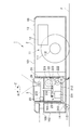
図2、3は、それぞれ電気掃除機の断面図であり、図2は、周辺検知部が突出した状態を示し、図3は、周辺検知部を収容した状態を示す断面図ある。
図2、3に示すように、センサ部3は、掃除機本体2の上方に突出した突出位置(図2)と、掃除機本体2のガイド筒103に収容された収容位置(図3)と、に亘って昇降可能に設けられている。ここで、突出位置としては、LRF20が掃除機本体2の上面101からわずかに突出した突出最下位置から、センサ部3がガイド筒103に対して最も上昇可能な突出最上位置まで、の高さ範囲を意味する。
図2、3に示すように、センサ部3は、掃除機本体2の上方に突出した突出位置(図2)と、掃除機本体2のガイド筒103に収容された収容位置(図3)と、に亘って昇降可能に設けられている。ここで、突出位置としては、LRF20が掃除機本体2の上面101からわずかに突出した突出最下位置から、センサ部3がガイド筒103に対して最も上昇可能な突出最上位置まで、の高さ範囲を意味する。
筒体21の底部には、支持板212が設けられ、この支持板212の周囲には、ガイド筒103のガイド溝104に案内される複数の突起213が形成されている。従って、センサ部3は、ボディ10の上面101と直交する垂直軸Zに沿って昇降自在、かつ、ボディ10の上面101と平行な面内に沿った回転方向Rに回転不能に、ガイド筒103に支持されている。
センサ部3を昇降させる昇降駆動部22は、筒体21の内部に固定される昇降モータ221と、昇降モータ221の出力軸の回転数を減速させる複数の昇降ギア222と、ボディ10に固定されて昇降ギア222の最終ギアに噛合するラック223と、を備える。この昇降駆動部22は、昇降モータ221の回転を昇降ギア222で減速させてラック223に伝達することで、ラック223に沿ってセンサ部3を昇降させるように構成されている。
回転駆動部23は、筒体21の支持板212に固定される回転モータ231と、回転モータ231の出力軸に噛合する回転ギア232と、回転ギア232に連結されて筒体21の内部で垂直軸Z回りに回転可能な回転体233と、を備え、回転体233にLRF20が固定されている。この回転駆動部23は、回転モータ231の回転を回転ギア232から回転体233に伝達することで、回転方向Rに沿ってLRF20を回転させるように構成されている。
上方センサ24は、超音波センサ等の距離センサであって、筒体21の上面から上方に向かって超音波を照射し、照射した超音波が障害物に当たって反射して戻るまでの時間から障害物との距離を算出する上方検知手段として機能する。この上方センサ24は、制御部12の指令によって検知のON/OFFが制御され、ONされることでセンサ部3の上方の障害物を検知する。具体的には、センサ部3が突出最上位置にある場合に検知がOFFにされ、センサ部3が突出最上位置から一定高さだけ下降された場合と収容位置にある場合に検知がONにされる。
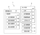
図4は、自走式掃除機の概略構成を示す機能ブロック図である。
掃除機本体2の制御部12は、走行駆動部11を制御する走行制御部121と、吸込み部14を制御する吸込制御部122と、LRF20および上方センサ24からの検出信号を処理して周辺の障害物までの距離を演算する検出演算部123と、昇降駆動部22および回転駆動部23を駆動制御する昇降制御部としての検出制御部124と、を備える。
掃除機本体2の制御部12は、走行駆動部11を制御する走行制御部121と、吸込み部14を制御する吸込制御部122と、LRF20および上方センサ24からの検出信号を処理して周辺の障害物までの距離を演算する検出演算部123と、昇降駆動部22および回転駆動部23を駆動制御する昇降制御部としての検出制御部124と、を備える。
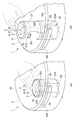
図5(A),(B)は、自走式掃除機の動作を示す斜視図であり、図6は、周辺検知部が突出した状態の動作を示し、図7は、周辺検知部を収容した状態の動作を示す断面図である。
以下、図5~7も参照しつつ自走式掃除機1の動作について説明する。自走式掃除機1の電源がONされると、制御部12の走行制御部121は、予め設定された走行プログラムに応じて走行駆動部11を駆動制御し、モータ112によって車輪111を回転させて掃除機本体2を自走させる。掃除機本体2の走行に伴って、吸込制御部122は、吸込み部14を制御して吸込み動作を開始させる。
以下、図5~7も参照しつつ自走式掃除機1の動作について説明する。自走式掃除機1の電源がONされると、制御部12の走行制御部121は、予め設定された走行プログラムに応じて走行駆動部11を駆動制御し、モータ112によって車輪111を回転させて掃除機本体2を自走させる。掃除機本体2の走行に伴って、吸込制御部122は、吸込み部14を制御して吸込み動作を開始させる。
清掃を開始すると同時に、検出制御部124は、昇降駆動部22の昇降モータ221を駆動してセンサ部3を突出位置(突出最上位置)まで上昇させるとともに、回転駆動部23の回転モータ231を駆動して回転体233およびLRF20を回転させる。また、走行中において、検出制御部124は、昇降駆動部22の昇降モータ221を駆動してセンサ部3を突出位置の範囲で適宜に昇降させる。このように自走式掃除機1は、突出位置に上昇させたセンサ部3のLRF20によって、周辺の障害物の有無および障害物までの距離を検出しながら、走行駆動部11によって自走しつつ吸込み部14によって床面Fの清掃を実施する。
検出演算部123は、LRF20から送信される検出信号を処理して周辺の障害物までの距離を算出する。昇降モータ221は、検出制御部124によって回転角が制御されるステッピングモータであり、検出演算部123は、昇降モータ221の回転角からセンサ部3の高さ位置を算出する。回転モータ231は、検出制御部124によって回転角が制御されるステッピングモータであり、検出演算部123は、回転モータ231の回転角から回転体233およびLRF20の回転位置を算出する。
図6に示すように、センサ部3が突出位置にある場合、回転駆動部23は、回転モータ231によって回転体233を垂直軸Z回りに略360°回転させ、LRF20によって掃除機本体2の略全周に亘って障害物を検出する。すなわち、検出演算部123は、LRF20の高さ位置および回転位置と、障害物までの距離と、に基づく演算を実行することによって、掃除機本体2の周辺にある障害物の位置を三次元的に認識することができる。
具体的には、図5(A)に示すように、走行方向の前方にソファやテーブルのような障害物Sを検出した場合、検出制御部124は、昇降駆動部22の昇降モータ221を駆動させてセンサ部3を下降させる。検出した障害物Sの底面S1と床面Fとに隙間がある場合、センサ部3の下降に伴って障害物Sが検出されなくなり、検出演算部123は、障害物Sの底面S1の高さを認識することができる。そこで、検出演算部123は、障害物Sの底面S1と床面Fとの隙間が走行可能か否かを判断する。
検出演算部123は、隙間の高さに基づき、センサ部3が突出位置にある状態のままで走行可能か、センサ部3を収容位置まで下降させれば走行可能か、センサ部3を収容位置まで下降させても走行不能か、を判断する。走行不能と判断した場合には、障害物Sの下に入り込むことを諦め、走行プログラムに応じた最寄りの走行ルートに移動し清掃を継続する。センサ部3が突出位置にある状態のままで走行可能と判断した場合には、図5(B)に示すように、自走式掃除機1は障害物Sの下に入り込んで清掃を継続する。
このようにセンサ部3を下降させて障害物Sの下に入り込む際には、制御部12は、上方センサ24を起動して検知を開始させ、検出演算部123は、上方センサ24から送信される検出信号を処理して障害物Sの底面S1までの距離を算出する。障害物Sの底面S1と床面Fとの隙間から自走式掃除機1が抜け出し、上方センサ24によって底面S1が検知されなくなったら、検出制御部124は、昇降駆動部22の昇降モータ221を駆動してセンサ部3を突出位置まで上昇させ、制御部12は、上方センサ24を停止させるとともに清掃を継続する。
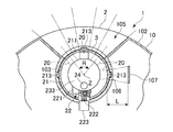
一方、センサ部3を収容位置まで下降させれば走行可能と判断した場合、検出制御部124は、センサ部3を収容位置まで下降させる。センサ部3が収容位置にある場合、LRF20は、図7に示すように、ボディ10の開口部105を通して掃除機本体2の前方側の所定範囲を検知できるようになっている。開口部105の幅寸法としては、例えば、LRF20の検知範囲が略90°になるように設定されている。また、回転駆動部23は、回転モータ231によって回転体233を前方側の略90°の範囲だけ回転させ、LRF20によって掃除機本体2の前方側の障害物を検出する。
センサ部3を収容位置まで下降させたら、LRF20によって掃除機本体2の前方側を検知し、前方側に障害物が検出されない場合、走行制御部121は、走行駆動部11を前進方向に駆動し、障害物Sの底面S1と床面Fとの隙間に入り込んで清掃を継続する。隙間に入り込む際には、制御部12は、上方センサ24を起動して障害物Sの底面S1を検知させる。その後、上方センサ24によって底面S1が検知されなくなったら、検出制御部124は、昇降駆動部22の昇降モータ221を駆動してセンサ部3を突出位置まで上昇させる。
また、センサ部3が収容位置にある状態で障害物Sの底面S1と床面Fとの隙間に入り込んでから掃除機本体2の前方側に障害物が検出された場合、走行制御部121は、走行駆動部11を駆動して自走式掃除機1を転回させるか後進させ、障害物を回避してから走行プログラムに応じた走行ルートに復帰させる。走行ルートに復帰するとともに、上方センサ24による上方の障害物がないことを確認したら、検出制御部124は、昇降駆動部22の昇降モータ221を駆動してセンサ部3を突出位置まで上昇させ、走行プログラムに応じた清掃を再開する。
以上のようにして所定の走行プログラムが終了すると、走行制御部121が走行駆動部11を停止させるとともに、吸込制御部122が吸込み部14の動作を停止させる。さらに、検出制御部124は、昇降駆動部22の昇降モータ221を駆動してセンサ部3を収容位置まで下降させるとともに、回転駆動部23の回転モータ231を停止させ、制御部12は、自走式掃除機1を待機状態とする。
自走式掃除機1の待機状態において、制御部12は、LRF20の検出距離、高さ位置および回転位置に関してキャリブレーション(校正)を実施する。図7に示すように、掃除機本体2のガイド筒103の一部には、スリット106が形成され、ボディ10の内部には、スリット106に対応して被検知部としての壁部107が設けられている。壁部107は、LRF20から既知の距離Lだけ離れて設けられ、LRF20からスリット106を通して照射されたレーザー光を反射するように構成されている。従って、壁部107からの反射光に基づいてLRF20が距離を検出し、その検出距離と既知の距離Lとの差を検出演算部123が算出する。検出距離にずれがあった場合には、検出演算部123は、以降の検出においてずれ量を補正した検出距離を出力する。
また、壁部107の表面には、鉛直方向(垂直軸Zに沿った方向)と水平方向(回転方向Rに沿った方向)に関し、それぞれ反射光の強さを変化させるパターンが設けられている。これらのパターンは、鉛直方向および水平方向の各方向について絶対位置を検出可能なアブソリュートパターンであり、各パターンが付与された反射光をLRF20が受光することで、検出演算部123は、LRF20の鉛直方向および水平方向の絶対位置を算出する。従って、算出したLRF20の絶対位置と、昇降駆動部22の昇降モータ221による高さ位置、および回転駆動部23の回転モータ231よる回転位置と、にずれがあった場合には、検出演算部123は、以降の検出においてずれ量を補正した高さ位置および回転位置を出力する。
このような本実施形態によれば、以下の作用・効果を奏することができる。
(1)掃除機本体2の上面101よりも上方の突出位置にあるLRF20が周辺を検知することで、広い範囲の障害物を検知することができ、障害物の有無や位置に応じて走行制御部121が走行駆動部11を制御して障害物を回避することができる。従って、障害物に接触する前に回避動作を行うことができるとともに、回避する方向の障害物の有無も認識しつつ回避方向を選択することができるので、回避動作を効率よく行い清掃時間を短縮することができる。
(1)掃除機本体2の上面101よりも上方の突出位置にあるLRF20が周辺を検知することで、広い範囲の障害物を検知することができ、障害物の有無や位置に応じて走行制御部121が走行駆動部11を制御して障害物を回避することができる。従って、障害物に接触する前に回避動作を行うことができるとともに、回避する方向の障害物の有無も認識しつつ回避方向を選択することができるので、回避動作を効率よく行い清掃時間を短縮することができる。
(2)検出制御部123が昇降駆動部22を駆動してLRF20を昇降させることで、周辺の検出範囲を変更することができ、より効率的に障害物を検出することができる。また、LRF20を収容位置まで下降させれば、上方に突出したセンサ部3が邪魔になることがなく清掃エリアを狭めずに清掃することができる。
(3)掃除機本体2よりも上方にある障害物を検知し、その障害物にセンサ部3が接触しそうだと判断した場合には、センサ部3を下降させることで障害物を避けて、障害物の下に入り込んでいくことができる。
(4)収容位置にあるLRF20に壁部107を検知させ、その結果によってLRF20の検出距離を校正することで、LRF20の検出精度を良好に維持することができる。さらに、壁部107からの反射光に基づいてLRF20の鉛直方向および水平方向の絶対位置を算出し、その結果によってLRF20の高さ位置および回転位置を校正することで、LRF20による障害物の検出精度を向上させることができる。
(5)収容位置にあるLRF20が掃除機本体2の開口部105を通して前方側の所定領域を検知することで、LRF20が掃除機本体2に収容されていても前方の障害物を検知することができ、回避動作を行いつつ清掃を実施することができる。
(6)上方センサ24によってセンサ部3の上方の障害物を検知することで、センサ部3を下降させて障害物を回避した後に再びセンサ部3を上昇させる際に、障害物に衝突することなくセンサ部3を突出最上位置まで上昇させることができ、広い範囲の障害物を検知しつつ清掃を実施することができる。
〔第2実施形態〕
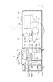
図8、9は、本発明の第2実施形態に係る自走式掃除機の断面図であり、図8は、周辺検知部が突出した状態を示し、図9は、周辺検知部を収容した状態を示す断面図ある。図10は、自走式掃除機の概略構成を示す機能ブロック図である。
本実施形態の自走式掃除機1は、前記第1実施形態と比較して、センサ部3を昇降させる昇降駆動部22、LRF20を回転させる回転駆動部23の構成が相違する。また、本実施形態の自走式掃除機1は、掃除機本体2に傾斜駆動部15を備えるとともに、センサ部3に外力検知部25を備え、制御部12が電源制御部125および傾斜制御部126を備える点が第1実施形態と相違する。
図8、9は、本発明の第2実施形態に係る自走式掃除機の断面図であり、図8は、周辺検知部が突出した状態を示し、図9は、周辺検知部を収容した状態を示す断面図ある。図10は、自走式掃除機の概略構成を示す機能ブロック図である。
本実施形態の自走式掃除機1は、前記第1実施形態と比較して、センサ部3を昇降させる昇降駆動部22、LRF20を回転させる回転駆動部23の構成が相違する。また、本実施形態の自走式掃除機1は、掃除機本体2に傾斜駆動部15を備えるとともに、センサ部3に外力検知部25を備え、制御部12が電源制御部125および傾斜制御部126を備える点が第1実施形態と相違する。
図8~10に示すように、掃除機本体2には、車輪111を上下させることで掃除機本体2の床面Fに対する傾斜角度を変更する傾斜駆動部15が設けられている。傾斜駆動部15は、掃除機本体2に一端側が回動自在に支持されるとともに他端側が走行駆動部11のモータ112に連結されたアーム151と、アーム151を上下方向に駆動するアクチュエータ152と、を備える。傾斜制御部126は、アクチュエータ152を伸縮駆動することで、アーム151を介して車輪111を上下させ、掃除機本体2の傾斜角度を変更する。
昇降駆動部22は、掃除機本体2の底部に固定された直動モータ224と、この直動モータ224の出力軸225の上端部に固定されたフランジ226と、を備え、フランジ226の上側に筒体21の支持板212が回転自在に載置されている。この昇降駆動部22は、直動モータ224を伸縮させることで、センサ部3を昇降させるように構成されている。また、直動モータ224には、センサ部3に外部から作用する外力を検知する外力検知部25が設けられている。外力検知部25は、センサ部3を上方から押し下げる外力が出力軸225を介して直動モータ224に作用した際に、その外力を検知し、検知信号を制御部12に送信する。
回転駆動部23は、筒体21の支持板212に固定された回転モータ234を備え、この回転モータ234の出力軸がフランジ226に連結されている。また、本実施形態において、LRF20は、センサ部3の筒体21および支持板212に固定されている。この回転駆動部23は、回転モータ234を回転させることで、フランジ226に対して支持板212、筒体21およびLRF20を回転させる。筒体21の下部外周面には、複数の鋼球214が回転自在に設けられ、ボディ10のガイド筒103内で筒体21が昇降、回転する際に、複数の鋼球214がガイド筒103の内面に沿って転動することで、ガイド筒103に対してセンサ部3を円滑に案内するボールベアリングとして機能するようになっている。
図11は、本実施形態の自走式掃除機の動作を示す斜視図である。
本実施形態の自走式掃除機1において、センサ部3は、自走式掃除機1の電源ボタンとしても機能する。具体的には、図11(A)に示すように、自走式掃除機1が待機状態であってセンサ部3が収容位置にある場合に、使用者がセンサ部3を下方に押し下げると、その押し下げ力を外力検知部25が検知する。外力検知部25からの検知信号を制御部12が受信すると、電源制御部125は、電源をONして自走式掃除機1を起動する。一方、自走式掃除機1の動作中であってセンサ部3が突出位置にある場合に、使用者がセンサ部3を下方に押し下げると、その押し下げ力を外力検知部25が検知し、電源制御部125は、電源をOFFして自走式掃除機1を待機状態とする。
本実施形態の自走式掃除機1において、センサ部3は、自走式掃除機1の電源ボタンとしても機能する。具体的には、図11(A)に示すように、自走式掃除機1が待機状態であってセンサ部3が収容位置にある場合に、使用者がセンサ部3を下方に押し下げると、その押し下げ力を外力検知部25が検知する。外力検知部25からの検知信号を制御部12が受信すると、電源制御部125は、電源をONして自走式掃除機1を起動する。一方、自走式掃除機1の動作中であってセンサ部3が突出位置にある場合に、使用者がセンサ部3を下方に押し下げると、その押し下げ力を外力検知部25が検知し、電源制御部125は、電源をOFFして自走式掃除機1を待機状態とする。
また、外力検知部25は、第1実施形態における上方センサ24と同様に、センサ部3の上方にある障害物を検知する上方検知手段としても機能する。すなわち、第1実施形態の図5に示すように、障害物Sの底面S1と床面Fとの隙間に自走式掃除機1が入り込んで清掃を実施する際に、適宜なタイミングで検出制御部123が昇降駆動部22を駆動してセンサ部3を上昇させる。センサ部3が障害物Sの底面S1に接触すると、底面S1から作用する外力を外力検知部25が検知することで、上方に障害物Sがあることが認識され、検出制御部123はセンサ部3を下降させる。一方、センサ部3を上昇させて障害物Sに接触しなければ、検出制御部123は突出最上位置までセンサ部3を上昇させる。
図12は、本実施形態の自走式掃除機の他の動作を示す斜視図である。
本実施形態の自走式掃除機1において、センサ部3は、その昇降動作によって使用者にメッセージを伝達する伝達手段しても機能する。具体的には、図12に示すように、センサ部3が突出位置にある場合に、検出制御部123が昇降駆動部22を駆動してセンサ部3を昇降させるか、検出制御部123が回転駆動部23を駆動してセンサ部3を回転させるか、あるいはセンサ部3を昇降させつつ回転させることで、自走式掃除機1の状態などを使用者に伝達する。
本実施形態の自走式掃除機1において、センサ部3は、その昇降動作によって使用者にメッセージを伝達する伝達手段しても機能する。具体的には、図12に示すように、センサ部3が突出位置にある場合に、検出制御部123が昇降駆動部22を駆動してセンサ部3を昇降させるか、検出制御部123が回転駆動部23を駆動してセンサ部3を回転させるか、あるいはセンサ部3を昇降させつつ回転させることで、自走式掃除機1の状態などを使用者に伝達する。
ここで、自走式掃除機1の状態としては、例えば、バッテリの充電が低下したことや、集塵室に集めた塵が所定容量に達したこと、集塵室のフィルタの交換時期がきたこと、走行プログラムに応じた清掃が完了したこと、障害物のために走行プログラムに応じた清掃ができなかったこと、など各種の情報がある。また、掃除ロボットとしての自走式掃除機1の喜怒哀楽などの感情表現をセンサ部3の動作によって使用者に伝達してもよい。このようなセンサ部3の昇降動作としては、昇降回数や昇降速度、回転の往復回数や回転速度の組み合わせによって複数の状態を表現することが可能である。
図13は、本実施形態の自走式掃除機のさらに他の動作を示す断面図である。
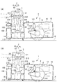
図13(A)に示すように、傾斜駆動部15がアクチュエータ152を伸ばすことで、アーム151を介して車輪111を下降させ、掃除機本体2の後部を上昇させて前下がりに傾斜させる。このように自走式掃除機1全体が前下がりの傾斜角度とされることで、LRF20の検知範囲としては、前方側においては床面Fの手前側(自走式掃除機1に近い側)となり、後方側においては遠方側かつ上方となる。
図13(A)に示すように、傾斜駆動部15がアクチュエータ152を伸ばすことで、アーム151を介して車輪111を下降させ、掃除機本体2の後部を上昇させて前下がりに傾斜させる。このように自走式掃除機1全体が前下がりの傾斜角度とされることで、LRF20の検知範囲としては、前方側においては床面Fの手前側(自走式掃除機1に近い側)となり、後方側においては遠方側かつ上方となる。
図13(B)に示すように、傾斜駆動部15がアクチュエータ152を縮めることで、アーム151を介して車輪111を上昇させ、掃除機本体2の後部を下降させて前上がりに傾斜させる。このように自走式掃除機1全体が前上がりの傾斜角度とされることで、LRF20の検知範囲としては、前方側においては床面Fの遠方側となり、後方側においては手前側となる。
このように本実施形態では、自走式掃除機1全体の傾斜角度を変更することで、LRF20による検知範囲を変更することができる。従って、第1実施形態と同様に走行プログラムに従った清掃を実施している清掃中において、センサ部3を昇降させることに加えて、自走式掃除機1全体の傾斜角度を変更した状態でLRF20が回転しつつ周辺を検知することで、周辺の障害物の検知範囲を三次元的に広げることができるようになっている。
このような本実施形態によれば、前記(1)~(5)の効果に加え以下の作用・効果を奏することができる。
(7)外力検知部25によってセンサ部3に作用する外力を検知することで、センサ部3を自走式掃除機1の電源ボタンとして機能させることができるとともに、上方にある障害物を検知する上方検知手段としてもセンサ部3を機能させることができる。
(7)外力検知部25によってセンサ部3に作用する外力を検知することで、センサ部3を自走式掃除機1の電源ボタンとして機能させることができるとともに、上方にある障害物を検知する上方検知手段としてもセンサ部3を機能させることができる。
(8)センサ部3の昇降動作および回転動作によって使用者にメッセージを伝達することで、自走式掃除機1の状態を分かりやすく伝達することができるとともに、ユーザーフレンドリーな情報伝達手段(ユーザーインターフェース)としてセンサ部3を利用することができる。
(9)傾斜駆動部15によって自走式掃除機1全体の傾斜角度を変更することで、LRF20による検知範囲を三次元的に広げることができ、周辺の障害物の検出精度を向上させることができる。
〔実施形態の変形〕
なお、本発明は、前記実施形態に限定されるものではなく、本発明の目的を達成できる範囲での変形、改良等は本発明に含まれるものである。
例えば、前記実施形態では、周辺検知部としてLRF20を用いたが、周辺検知部は、LRF(Laser Range Finder)20に限らず、任意の検知手段が利用可能である。検知手段としては、例えば、超音波センサや光センサ、電磁式センサでもよいし、CCDカメラ等の撮像手段であってもよい。撮像手段を用いる場合には、制御部に画像処理手段等を設けて画像解析によって周辺の障害物を検知するように構成すればよい。
なお、本発明は、前記実施形態に限定されるものではなく、本発明の目的を達成できる範囲での変形、改良等は本発明に含まれるものである。
例えば、前記実施形態では、周辺検知部としてLRF20を用いたが、周辺検知部は、LRF(Laser Range Finder)20に限らず、任意の検知手段が利用可能である。検知手段としては、例えば、超音波センサや光センサ、電磁式センサでもよいし、CCDカメラ等の撮像手段であってもよい。撮像手段を用いる場合には、制御部に画像処理手段等を設けて画像解析によって周辺の障害物を検知するように構成すればよい。
前記第1実施形態では、センサ部3において回転駆動部23に駆動されてLRF20が回転し、前記第2実施形態では、回転駆動部23によってセンサ部3とともにLRF20が回転する構成であったが、周辺検知部は回転するものに限られない。すなわち、周辺検知部は、互いに異なる方向を検知可能が複数のセンサで構成されていてもよく、このような構成とすれば、回転駆動部を省略することができる。また、前記実施形態では、掃除機本体2の開口部105が前方側に設けられていたが、開口部は掃除機本体の任意の位置に設けられていればよい。
また、前記第1実施形態では、昇降駆動部22が昇降モータ221、昇降ギア222、ラック223を備え、前記第2実施形態では、昇降駆動部22が直動モータ224を備えて構成されていたが、昇降駆動部の構成は前記実施形態に限定されるものではなく、各種の駆動機構が利用可能である。また、周辺検知部を回転させる回転駆動部や、車輪を上下させる傾斜駆動部としても、前記実施形態の構成に限定されず、各種の駆動機構が利用可能である。
前記第1実施形態では、上方センサ24によってセンサ部3の上方の障害物を検知し、前記第2実施形態では、外力検知部25によって上方の障害物を検知する構成としたが、このような上方検知手段は必須ではなく省略することができる。上方検知手段を省略した場合には、周辺検知部を用いて上方の障害物を検知してもよいし、上方の障害物を検知することなく周辺検知部を昇降させてもよい。
前記第2実施形態では、外力検知部25によってセンサ部3を押し下げる使用者からの操作を検知することで、センサ部3を自走式掃除機1の電源ボタンとして機能させたが、センサ部3の押し下げ操作は電源のON/OFFに限らず、自走式掃除機1の一時停止/再開に利用してもよいし、清掃モードの切り替えに利用してもよく、任意の操作を実行させるための操作部として機能させることができる。
以上のように、本発明は、障害物の回避動作を効率よく行い清掃時間を短縮することができる自走式掃除機に好適に利用できる。
1 自走式掃除機
2 掃除機本体
3 センサ部
10 ボディ
11 走行駆動部
12 制御部
15 傾斜駆動部
20 LRF(周辺検知部)
22 昇降駆動部
23 回転駆動部
25 外力検知部
105 開口部
107 壁部(被検出部)
111 車輪
121 走行制御部
124 検出制御部(昇降制御部)
F 床面
2 掃除機本体
3 センサ部
10 ボディ
11 走行駆動部
12 制御部
15 傾斜駆動部
20 LRF(周辺検知部)
22 昇降駆動部
23 回転駆動部
25 外力検知部
105 開口部
107 壁部(被検出部)
111 車輪
121 走行制御部
124 検出制御部(昇降制御部)
F 床面
Claims (7)
- 床面に沿って走行しつつ清掃可能な自走式掃除機であって、
自走するための車輪を有する掃除機本体と、
前記車輪を駆動する走行駆動部と、
前記掃除機本体の周辺を検知するための周辺検知部と、
前記掃除機本体よりも上方の突出位置と該掃除機本体内部の収容位置とに亘って前記周辺検知部を昇降させる昇降駆動部と、
前記走行駆動部を制御する走行制御部と、
前記昇降駆動部を制御する昇降制御部と、を備え、
前記昇降制御部が前記昇降駆動部を駆動して前記周辺検知部を昇降させることを特徴とする自走式掃除機。 - 請求項1に記載された自走式掃除機において、
前記昇降制御部は、前記周辺検知部が前記掃除機本体よりも上方の障害物を検知した場合に、その障害物を避ける位置まで前記周辺検知部を下降させることを特徴とする自走式掃除機。 - 請求項1または請求項2に記載された自走式掃除機において、
前記掃除機本体の内部には、被検知部が設けられ、
前記収容位置にある前記周辺検知部に前記被検知部を検知させることで該周辺検知部の測定値を校正することを特徴とする自走式掃除機。 - 請求項1から請求項3のいずれかに記載された自走式掃除機において、
前記掃除機本体には、所定方向に向かって開口した開口部が設けられ、
前記収容位置にある前記周辺検知部が前記開口部を通して前記掃除機本体の所定方向を検知することを特徴とする自走式掃除機。 - 請求項1から請求項4のいずれかに記載された自走式掃除機において、
前記昇降制御部は、前記周辺検知部を昇降させる昇降動作によって使用者にメッセージを伝達することを特徴とする自走式掃除機。 - 請求項1から請求項5のいずれかに記載された自走式掃除機において、
前記周辺検知部に外部から作用する外力を検知する外力検知部をさらに備え、
前記外力検知部による外力の検知に基づいて前記掃除機本体の動作を切り替えることを特徴とする自走式掃除機。 - 請求項1から請求項6のいずれかに記載された自走式掃除機において、
前記車輪を上下させることで前記掃除機本体の床面に対する傾斜角度を変更する傾斜駆動部をさらに備えることを特徴とする自走式掃除機。
Priority Applications (5)
| Application Number | Priority Date | Filing Date | Title |
|---|---|---|---|
| CN201780089322.XA CN110520027B (zh) | 2017-06-07 | 2017-06-07 | 自走式扫除机 |
| PCT/JP2017/021101 WO2018225172A1 (ja) | 2017-06-07 | 2017-06-07 | 自走式掃除機 |
| EP17912390.6A EP3636127A4 (en) | 2017-06-07 | 2017-06-07 | SELF-PROPELLED VACUUM CLEANER |
| JP2019523258A JPWO2018225172A1 (ja) | 2017-06-07 | 2017-06-07 | 自走式掃除機 |
| US16/617,139 US20210137342A1 (en) | 2017-06-07 | 2017-06-07 | Self-propelled vacuum cleaner |
Applications Claiming Priority (1)
| Application Number | Priority Date | Filing Date | Title |
|---|---|---|---|
| PCT/JP2017/021101 WO2018225172A1 (ja) | 2017-06-07 | 2017-06-07 | 自走式掃除機 |
Publications (1)
| Publication Number | Publication Date |
|---|---|
| WO2018225172A1 true WO2018225172A1 (ja) | 2018-12-13 |
Family
ID=64566567
Family Applications (1)
| Application Number | Title | Priority Date | Filing Date |
|---|---|---|---|
| PCT/JP2017/021101 Ceased WO2018225172A1 (ja) | 2017-06-07 | 2017-06-07 | 自走式掃除機 |
Country Status (5)
| Country | Link |
|---|---|
| US (1) | US20210137342A1 (ja) |
| EP (1) | EP3636127A4 (ja) |
| JP (1) | JPWO2018225172A1 (ja) |
| CN (1) | CN110520027B (ja) |
| WO (1) | WO2018225172A1 (ja) |
Cited By (4)
| Publication number | Priority date | Publication date | Assignee | Title |
|---|---|---|---|---|
| WO2020246776A1 (en) | 2019-06-04 | 2020-12-10 | Samsung Electronics Co., Ltd. | Robot cleaner |
| JP2021122395A (ja) * | 2020-02-03 | 2021-08-30 | 株式会社マキタ | 検出装置及びロボット集塵機 |
| DE102021206645A1 (de) | 2021-06-28 | 2022-12-29 | BSH Hausgeräte GmbH | Mobiles Bodenreinigungsgerät sowie Verfahren zum Betreiben desselben |
| EP3949818A4 (en) * | 2019-03-26 | 2023-04-05 | LG Electronics Inc. | ROBOT CLEANER |
Families Citing this family (7)
| Publication number | Priority date | Publication date | Assignee | Title |
|---|---|---|---|---|
| JP7369592B2 (ja) * | 2019-10-30 | 2023-10-26 | 株式会社マキタ | 検出装置及びロボット集塵機 |
| CN112515544B (zh) * | 2020-09-11 | 2025-07-11 | 深圳银星智能集团股份有限公司 | 智能机器人 |
| CN112882472A (zh) * | 2021-01-25 | 2021-06-01 | 追创科技(苏州)有限公司 | 自主移动设备 |
| DE102021202514B4 (de) | 2021-03-15 | 2023-03-02 | BSH Hausgeräte GmbH | Mobiles, selbstfahrendes Gerät |
| KR20230122878A (ko) * | 2022-02-15 | 2023-08-22 | 삼성전자주식회사 | 로봇청소기 |
| CN118303790B (zh) * | 2024-06-07 | 2024-10-29 | 追觅创新科技(苏州)有限公司 | 清洁设备的控制方法、清洁设备、系统及存储介质 |
| CN120000111A (zh) * | 2025-01-27 | 2025-05-16 | 北京石头创新科技有限公司 | 升降控制方法、系统、电子设备及存储介质 |
Citations (7)
| Publication number | Priority date | Publication date | Assignee | Title |
|---|---|---|---|---|
| JPS55146042U (ja) * | 1979-04-06 | 1980-10-20 | ||
| JPH07191142A (ja) * | 1993-12-27 | 1995-07-28 | Astecs Kk | 全方位距離検出装置 |
| JPH07260483A (ja) * | 1994-03-23 | 1995-10-13 | Fujita Corp | 移動体の位置・方向測定方法及びその装置 |
| JP2004223703A (ja) * | 2003-01-23 | 2004-08-12 | Lg Electronics Inc | 掃除用ロボットの位置情報認識装置及び掃除用ロボット本体 |
| JP2006155274A (ja) * | 2004-11-30 | 2006-06-15 | Hitachi Home & Life Solutions Inc | 自走式掃除機 |
| JP2012045383A (ja) * | 2010-08-23 | 2012-03-08 | Vorwerk & Co Interholding Gmbh | 自走式装置 |
| JP2016135303A (ja) | 2016-03-24 | 2016-07-28 | シャープ株式会社 | 自走式掃除機 |
Family Cites Families (9)
| Publication number | Priority date | Publication date | Assignee | Title |
|---|---|---|---|---|
| JP3225092B2 (ja) * | 1992-06-30 | 2001-11-05 | 富士重工業株式会社 | 自走機械 |
| JPH10315888A (ja) * | 1997-05-21 | 1998-12-02 | Fuji Heavy Ind Ltd | 車両用上方障害物警報装置 |
| JP2002310697A (ja) * | 2001-04-11 | 2002-10-23 | Denso Corp | 車両用高さ制限警告装置 |
| JP2005211365A (ja) * | 2004-01-30 | 2005-08-11 | Funai Electric Co Ltd | 自律走行ロボットクリーナー |
| KR101524797B1 (ko) * | 2008-10-17 | 2015-06-02 | 삼성전자주식회사 | 휠 어셈블리 |
| JP2014176509A (ja) * | 2013-03-14 | 2014-09-25 | Toshiba Corp | 電気掃除機 |
| DE102014110265A1 (de) * | 2014-07-22 | 2016-01-28 | Vorwerk & Co. Interholding Gmbh | Verfahren zur Reinigung oder Bearbeitung eines Raumes mittels eines selbsttätig verfahrbaren Gerätes |
| CN204950819U (zh) * | 2015-04-15 | 2016-01-13 | 小米科技有限责任公司 | 一种自动除尘装置 |
| CN205697560U (zh) * | 2016-03-30 | 2016-11-23 | 杭州寇古科技有限公司 | 一种智能扫地机器人 |
-
2017
- 2017-06-07 EP EP17912390.6A patent/EP3636127A4/en not_active Withdrawn
- 2017-06-07 WO PCT/JP2017/021101 patent/WO2018225172A1/ja not_active Ceased
- 2017-06-07 JP JP2019523258A patent/JPWO2018225172A1/ja active Pending
- 2017-06-07 US US16/617,139 patent/US20210137342A1/en not_active Abandoned
- 2017-06-07 CN CN201780089322.XA patent/CN110520027B/zh not_active Expired - Fee Related
Patent Citations (7)
| Publication number | Priority date | Publication date | Assignee | Title |
|---|---|---|---|---|
| JPS55146042U (ja) * | 1979-04-06 | 1980-10-20 | ||
| JPH07191142A (ja) * | 1993-12-27 | 1995-07-28 | Astecs Kk | 全方位距離検出装置 |
| JPH07260483A (ja) * | 1994-03-23 | 1995-10-13 | Fujita Corp | 移動体の位置・方向測定方法及びその装置 |
| JP2004223703A (ja) * | 2003-01-23 | 2004-08-12 | Lg Electronics Inc | 掃除用ロボットの位置情報認識装置及び掃除用ロボット本体 |
| JP2006155274A (ja) * | 2004-11-30 | 2006-06-15 | Hitachi Home & Life Solutions Inc | 自走式掃除機 |
| JP2012045383A (ja) * | 2010-08-23 | 2012-03-08 | Vorwerk & Co Interholding Gmbh | 自走式装置 |
| JP2016135303A (ja) | 2016-03-24 | 2016-07-28 | シャープ株式会社 | 自走式掃除機 |
Non-Patent Citations (1)
| Title |
|---|
| See also references of EP3636127A4 * |
Cited By (9)
| Publication number | Priority date | Publication date | Assignee | Title |
|---|---|---|---|---|
| EP3949818A4 (en) * | 2019-03-26 | 2023-04-05 | LG Electronics Inc. | ROBOT CLEANER |
| WO2020246776A1 (en) | 2019-06-04 | 2020-12-10 | Samsung Electronics Co., Ltd. | Robot cleaner |
| CN113710137A (zh) * | 2019-06-04 | 2021-11-26 | 三星电子株式会社 | 机器人清洁器 |
| EP3962338A4 (en) * | 2019-06-04 | 2022-11-30 | Samsung Electronics Co., Ltd. | ROBOT CLEANER |
| US11659971B2 (en) | 2019-06-04 | 2023-05-30 | Samsung Electronics Co., Ltd. | Robot cleaner |
| JP2021122395A (ja) * | 2020-02-03 | 2021-08-30 | 株式会社マキタ | 検出装置及びロボット集塵機 |
| JP7430540B2 (ja) | 2020-02-03 | 2024-02-13 | 株式会社マキタ | 検出装置及びロボット集塵機 |
| DE102021206645A1 (de) | 2021-06-28 | 2022-12-29 | BSH Hausgeräte GmbH | Mobiles Bodenreinigungsgerät sowie Verfahren zum Betreiben desselben |
| DE102021206645B4 (de) | 2021-06-28 | 2023-04-27 | BSH Hausgeräte GmbH | Mobiles Bodenreinigungsgerät sowie Verfahren zum Betreiben desselben |
Also Published As
| Publication number | Publication date |
|---|---|
| EP3636127A4 (en) | 2021-01-27 |
| JPWO2018225172A1 (ja) | 2019-11-07 |
| CN110520027A (zh) | 2019-11-29 |
| EP3636127A1 (en) | 2020-04-15 |
| CN110520027B (zh) | 2021-05-07 |
| US20210137342A1 (en) | 2021-05-13 |
Similar Documents
| Publication | Publication Date | Title |
|---|---|---|
| JPWO2018225172A1 (ja) | 自走式掃除機 | |
| JP7023530B2 (ja) | 自走式掃除機 | |
| AU2013203861B2 (en) | Method of controlling automatic cleaner | |
| JP4181477B2 (ja) | 自走式掃除機 | |
| KR101840149B1 (ko) | 자율주행체 및 전기청소기 | |
| JP6888847B2 (ja) | 自走式掃除機 | |
| KR102281346B1 (ko) | 로봇 청소기 및 그 제어방법 | |
| KR20170000071A (ko) | 진공 청소기 및 그의 제어방법 | |
| US20200405115A1 (en) | Self-propelled vacuum cleaner | |
| CN111107774A (zh) | 自走式扫除机 | |
| KR101469333B1 (ko) | 자동 청소기 | |
| CN113613536A (zh) | 机器人清扫器 | |
| JPWO2018123321A1 (ja) | 自律走行型掃除機 | |
| JP2017064064A (ja) | 電気掃除機 | |
| JP2021010761A (ja) | 自走式掃除機 | |
| TW201737853A (zh) | 自主行走型清掃機 | |
| JP2005211499A (ja) | 自走式掃除機 | |
| JP2021007051A (ja) | 自走式掃除機 | |
| JP2019141313A (ja) | 自走式掃除機 | |
| HK40011698A (en) | Self-propelled vacuum cleaner | |
| HK40011698B (zh) | 自走式扫除机 | |
| JP2005218578A (ja) | 自走式掃除機 | |
| CN113219961A (zh) | 自走式移动体、判断程序和判断方法 | |
| EP4248828A1 (en) | Robot cleaner | |
| JP2019111007A (ja) | 自走式掃除機 |
Legal Events
| Date | Code | Title | Description |
|---|---|---|---|
| 121 | Ep: the epo has been informed by wipo that ep was designated in this application |
Ref document number: 17912390 Country of ref document: EP Kind code of ref document: A1 |
|
| ENP | Entry into the national phase |
Ref document number: 2019523258 Country of ref document: JP Kind code of ref document: A |
|
| NENP | Non-entry into the national phase |
Ref country code: DE |
|
| ENP | Entry into the national phase |
Ref document number: 2017912390 Country of ref document: EP Effective date: 20200107 |