WO2018225221A1 - 熱源システム - Google Patents
熱源システム Download PDFInfo
- Publication number
- WO2018225221A1 WO2018225221A1 PCT/JP2017/021342 JP2017021342W WO2018225221A1 WO 2018225221 A1 WO2018225221 A1 WO 2018225221A1 JP 2017021342 W JP2017021342 W JP 2017021342W WO 2018225221 A1 WO2018225221 A1 WO 2018225221A1
- Authority
- WO
- WIPO (PCT)
- Prior art keywords
- water
- heat source
- load
- pump
- header pipe
- Prior art date
- Legal status (The legal status is an assumption and is not a legal conclusion. Google has not performed a legal analysis and makes no representation as to the accuracy of the status listed.)
- Ceased
Links
Images





Classifications
-
- F—MECHANICAL ENGINEERING; LIGHTING; HEATING; WEAPONS; BLASTING
- F24—HEATING; RANGES; VENTILATING
- F24F—AIR-CONDITIONING; AIR-HUMIDIFICATION; VENTILATION; USE OF AIR CURRENTS FOR SCREENING
- F24F11/00—Control or safety arrangements
- F24F11/30—Control or safety arrangements for purposes related to the operation of the system, e.g. for safety or monitoring
- F24F11/46—Improving electric energy efficiency or saving
-
- F—MECHANICAL ENGINEERING; LIGHTING; HEATING; WEAPONS; BLASTING
- F25—REFRIGERATION OR COOLING; COMBINED HEATING AND REFRIGERATION SYSTEMS; HEAT PUMP SYSTEMS; MANUFACTURE OR STORAGE OF ICE; LIQUEFACTION SOLIDIFICATION OF GASES
- F25B—REFRIGERATION MACHINES, PLANTS OR SYSTEMS; COMBINED HEATING AND REFRIGERATION SYSTEMS; HEAT PUMP SYSTEMS
- F25B13/00—Compression machines, plants or systems, with reversible cycle
-
- F—MECHANICAL ENGINEERING; LIGHTING; HEATING; WEAPONS; BLASTING
- F24—HEATING; RANGES; VENTILATING
- F24D—DOMESTIC- OR SPACE-HEATING SYSTEMS, e.g. CENTRAL HEATING SYSTEMS; DOMESTIC HOT-WATER SUPPLY SYSTEMS; ELEMENTS OR COMPONENTS THEREFOR
- F24D3/00—Hot-water central heating systems
- F24D3/18—Hot-water central heating systems using heat pumps
-
- F—MECHANICAL ENGINEERING; LIGHTING; HEATING; WEAPONS; BLASTING
- F24—HEATING; RANGES; VENTILATING
- F24F—AIR-CONDITIONING; AIR-HUMIDIFICATION; VENTILATION; USE OF AIR CURRENTS FOR SCREENING
- F24F11/00—Control or safety arrangements
- F24F11/70—Control systems characterised by their outputs; Constructional details thereof
- F24F11/80—Control systems characterised by their outputs; Constructional details thereof for controlling the temperature of the supplied air
- F24F11/83—Control systems characterised by their outputs; Constructional details thereof for controlling the temperature of the supplied air by controlling the supply of heat-exchange fluids to heat-exchangers
- F24F11/84—Control systems characterised by their outputs; Constructional details thereof for controlling the temperature of the supplied air by controlling the supply of heat-exchange fluids to heat-exchangers using valves
-
- F—MECHANICAL ENGINEERING; LIGHTING; HEATING; WEAPONS; BLASTING
- F24—HEATING; RANGES; VENTILATING
- F24F—AIR-CONDITIONING; AIR-HUMIDIFICATION; VENTILATION; USE OF AIR CURRENTS FOR SCREENING
- F24F11/00—Control or safety arrangements
- F24F11/70—Control systems characterised by their outputs; Constructional details thereof
- F24F11/80—Control systems characterised by their outputs; Constructional details thereof for controlling the temperature of the supplied air
- F24F11/83—Control systems characterised by their outputs; Constructional details thereof for controlling the temperature of the supplied air by controlling the supply of heat-exchange fluids to heat-exchangers
- F24F11/85—Control systems characterised by their outputs; Constructional details thereof for controlling the temperature of the supplied air by controlling the supply of heat-exchange fluids to heat-exchangers using variable-flow pumps
-
- F—MECHANICAL ENGINEERING; LIGHTING; HEATING; WEAPONS; BLASTING
- F25—REFRIGERATION OR COOLING; COMBINED HEATING AND REFRIGERATION SYSTEMS; HEAT PUMP SYSTEMS; MANUFACTURE OR STORAGE OF ICE; LIQUEFACTION SOLIDIFICATION OF GASES
- F25B—REFRIGERATION MACHINES, PLANTS OR SYSTEMS; COMBINED HEATING AND REFRIGERATION SYSTEMS; HEAT PUMP SYSTEMS
- F25B29/00—Combined heating and refrigeration systems, e.g. operating alternately or simultaneously
- F25B29/003—Combined heating and refrigeration systems, e.g. operating alternately or simultaneously of the compression type system
-
- F—MECHANICAL ENGINEERING; LIGHTING; HEATING; WEAPONS; BLASTING
- F24—HEATING; RANGES; VENTILATING
- F24F—AIR-CONDITIONING; AIR-HUMIDIFICATION; VENTILATION; USE OF AIR CURRENTS FOR SCREENING
- F24F2140/00—Control inputs relating to system states
- F24F2140/10—Pressure
- F24F2140/12—Heat-exchange fluid pressure
-
- F—MECHANICAL ENGINEERING; LIGHTING; HEATING; WEAPONS; BLASTING
- F24—HEATING; RANGES; VENTILATING
- F24F—AIR-CONDITIONING; AIR-HUMIDIFICATION; VENTILATION; USE OF AIR CURRENTS FOR SCREENING
- F24F2221/00—Details or features not otherwise provided for
- F24F2221/54—Heating and cooling, simultaneously or alternatively
-
- F—MECHANICAL ENGINEERING; LIGHTING; HEATING; WEAPONS; BLASTING
- F24—HEATING; RANGES; VENTILATING
- F24F—AIR-CONDITIONING; AIR-HUMIDIFICATION; VENTILATION; USE OF AIR CURRENTS FOR SCREENING
- F24F5/00—Air-conditioning systems or apparatus not covered by F24F1/00 or F24F3/00, e.g. using solar heat or combined with household units such as an oven or water heater
-
- F—MECHANICAL ENGINEERING; LIGHTING; HEATING; WEAPONS; BLASTING
- F25—REFRIGERATION OR COOLING; COMBINED HEATING AND REFRIGERATION SYSTEMS; HEAT PUMP SYSTEMS; MANUFACTURE OR STORAGE OF ICE; LIQUEFACTION SOLIDIFICATION OF GASES
- F25B—REFRIGERATION MACHINES, PLANTS OR SYSTEMS; COMBINED HEATING AND REFRIGERATION SYSTEMS; HEAT PUMP SYSTEMS
- F25B1/00—Compression machines, plants or systems with non-reversible cycle
-
- F—MECHANICAL ENGINEERING; LIGHTING; HEATING; WEAPONS; BLASTING
- F25—REFRIGERATION OR COOLING; COMBINED HEATING AND REFRIGERATION SYSTEMS; HEAT PUMP SYSTEMS; MANUFACTURE OR STORAGE OF ICE; LIQUEFACTION SOLIDIFICATION OF GASES
- F25B—REFRIGERATION MACHINES, PLANTS OR SYSTEMS; COMBINED HEATING AND REFRIGERATION SYSTEMS; HEAT PUMP SYSTEMS
- F25B2313/00—Compression machines, plants or systems with reversible cycle not otherwise provided for
- F25B2313/003—Indoor unit with water as a heat sink or heat source
-
- F—MECHANICAL ENGINEERING; LIGHTING; HEATING; WEAPONS; BLASTING
- F25—REFRIGERATION OR COOLING; COMBINED HEATING AND REFRIGERATION SYSTEMS; HEAT PUMP SYSTEMS; MANUFACTURE OR STORAGE OF ICE; LIQUEFACTION SOLIDIFICATION OF GASES
- F25B—REFRIGERATION MACHINES, PLANTS OR SYSTEMS; COMBINED HEATING AND REFRIGERATION SYSTEMS; HEAT PUMP SYSTEMS
- F25B2313/00—Compression machines, plants or systems with reversible cycle not otherwise provided for
- F25B2313/023—Compression machines, plants or systems with reversible cycle not otherwise provided for using multiple indoor units
- F25B2313/0231—Compression machines, plants or systems with reversible cycle not otherwise provided for using multiple indoor units with simultaneous cooling and heating
-
- F—MECHANICAL ENGINEERING; LIGHTING; HEATING; WEAPONS; BLASTING
- F25—REFRIGERATION OR COOLING; COMBINED HEATING AND REFRIGERATION SYSTEMS; HEAT PUMP SYSTEMS; MANUFACTURE OR STORAGE OF ICE; LIQUEFACTION SOLIDIFICATION OF GASES
- F25B—REFRIGERATION MACHINES, PLANTS OR SYSTEMS; COMBINED HEATING AND REFRIGERATION SYSTEMS; HEAT PUMP SYSTEMS
- F25B2313/00—Compression machines, plants or systems with reversible cycle not otherwise provided for
- F25B2313/027—Compression machines, plants or systems with reversible cycle not otherwise provided for characterised by the reversing means
- F25B2313/02741—Compression machines, plants or systems with reversible cycle not otherwise provided for characterised by the reversing means using one four-way valve
-
- F—MECHANICAL ENGINEERING; LIGHTING; HEATING; WEAPONS; BLASTING
- F25—REFRIGERATION OR COOLING; COMBINED HEATING AND REFRIGERATION SYSTEMS; HEAT PUMP SYSTEMS; MANUFACTURE OR STORAGE OF ICE; LIQUEFACTION SOLIDIFICATION OF GASES
- F25B—REFRIGERATION MACHINES, PLANTS OR SYSTEMS; COMBINED HEATING AND REFRIGERATION SYSTEMS; HEAT PUMP SYSTEMS
- F25B2313/00—Compression machines, plants or systems with reversible cycle not otherwise provided for
- F25B2313/031—Sensor arrangements
- F25B2313/0312—Pressure sensors near the indoor heat exchanger
-
- F—MECHANICAL ENGINEERING; LIGHTING; HEATING; WEAPONS; BLASTING
- F25—REFRIGERATION OR COOLING; COMBINED HEATING AND REFRIGERATION SYSTEMS; HEAT PUMP SYSTEMS; MANUFACTURE OR STORAGE OF ICE; LIQUEFACTION SOLIDIFICATION OF GASES
- F25B—REFRIGERATION MACHINES, PLANTS OR SYSTEMS; COMBINED HEATING AND REFRIGERATION SYSTEMS; HEAT PUMP SYSTEMS
- F25B2313/00—Compression machines, plants or systems with reversible cycle not otherwise provided for
- F25B2313/031—Sensor arrangements
- F25B2313/0314—Temperature sensors near the indoor heat exchanger
-
- F—MECHANICAL ENGINEERING; LIGHTING; HEATING; WEAPONS; BLASTING
- F25—REFRIGERATION OR COOLING; COMBINED HEATING AND REFRIGERATION SYSTEMS; HEAT PUMP SYSTEMS; MANUFACTURE OR STORAGE OF ICE; LIQUEFACTION SOLIDIFICATION OF GASES
- F25B—REFRIGERATION MACHINES, PLANTS OR SYSTEMS; COMBINED HEATING AND REFRIGERATION SYSTEMS; HEAT PUMP SYSTEMS
- F25B2339/00—Details of evaporators; Details of condensers
- F25B2339/04—Details of condensers
- F25B2339/047—Water-cooled condensers
-
- F—MECHANICAL ENGINEERING; LIGHTING; HEATING; WEAPONS; BLASTING
- F25—REFRIGERATION OR COOLING; COMBINED HEATING AND REFRIGERATION SYSTEMS; HEAT PUMP SYSTEMS; MANUFACTURE OR STORAGE OF ICE; LIQUEFACTION SOLIDIFICATION OF GASES
- F25B—REFRIGERATION MACHINES, PLANTS OR SYSTEMS; COMBINED HEATING AND REFRIGERATION SYSTEMS; HEAT PUMP SYSTEMS
- F25B2400/00—Component parts or details not otherwise provided for in this subclass
- F25B2400/06—Several compression cycles arranged in parallel
-
- F—MECHANICAL ENGINEERING; LIGHTING; HEATING; WEAPONS; BLASTING
- F25—REFRIGERATION OR COOLING; COMBINED HEATING AND REFRIGERATION SYSTEMS; HEAT PUMP SYSTEMS; MANUFACTURE OR STORAGE OF ICE; LIQUEFACTION SOLIDIFICATION OF GASES
- F25B—REFRIGERATION MACHINES, PLANTS OR SYSTEMS; COMBINED HEATING AND REFRIGERATION SYSTEMS; HEAT PUMP SYSTEMS
- F25B2600/00—Control issues
- F25B2600/02—Compressor control
- F25B2600/025—Compressor control by controlling speed
- F25B2600/0253—Compressor control by controlling speed with variable speed
-
- F—MECHANICAL ENGINEERING; LIGHTING; HEATING; WEAPONS; BLASTING
- F25—REFRIGERATION OR COOLING; COMBINED HEATING AND REFRIGERATION SYSTEMS; HEAT PUMP SYSTEMS; MANUFACTURE OR STORAGE OF ICE; LIQUEFACTION SOLIDIFICATION OF GASES
- F25B—REFRIGERATION MACHINES, PLANTS OR SYSTEMS; COMBINED HEATING AND REFRIGERATION SYSTEMS; HEAT PUMP SYSTEMS
- F25B2700/00—Sensing or detecting of parameters; Sensors therefor
- F25B2700/21—Temperatures
- F25B2700/2116—Temperatures of a condenser
- F25B2700/21161—Temperatures of a condenser of the fluid heated by the condenser
-
- F—MECHANICAL ENGINEERING; LIGHTING; HEATING; WEAPONS; BLASTING
- F25—REFRIGERATION OR COOLING; COMBINED HEATING AND REFRIGERATION SYSTEMS; HEAT PUMP SYSTEMS; MANUFACTURE OR STORAGE OF ICE; LIQUEFACTION SOLIDIFICATION OF GASES
- F25B—REFRIGERATION MACHINES, PLANTS OR SYSTEMS; COMBINED HEATING AND REFRIGERATION SYSTEMS; HEAT PUMP SYSTEMS
- F25B2700/00—Sensing or detecting of parameters; Sensors therefor
- F25B2700/21—Temperatures
- F25B2700/2117—Temperatures of an evaporator
- F25B2700/21171—Temperatures of an evaporator of the fluid cooled by the evaporator
- F25B2700/21173—Temperatures of an evaporator of the fluid cooled by the evaporator at the outlet
-
- F—MECHANICAL ENGINEERING; LIGHTING; HEATING; WEAPONS; BLASTING
- F25—REFRIGERATION OR COOLING; COMBINED HEATING AND REFRIGERATION SYSTEMS; HEAT PUMP SYSTEMS; MANUFACTURE OR STORAGE OF ICE; LIQUEFACTION SOLIDIFICATION OF GASES
- F25B—REFRIGERATION MACHINES, PLANTS OR SYSTEMS; COMBINED HEATING AND REFRIGERATION SYSTEMS; HEAT PUMP SYSTEMS
- F25B49/00—Arrangement or mounting of control or safety devices
- F25B49/02—Arrangement or mounting of control or safety devices for compression type machines, plants or systems
-
- Y—GENERAL TAGGING OF NEW TECHNOLOGICAL DEVELOPMENTS; GENERAL TAGGING OF CROSS-SECTIONAL TECHNOLOGIES SPANNING OVER SEVERAL SECTIONS OF THE IPC; TECHNICAL SUBJECTS COVERED BY FORMER USPC CROSS-REFERENCE ART COLLECTIONS [XRACs] AND DIGESTS
- Y02—TECHNOLOGIES OR APPLICATIONS FOR MITIGATION OR ADAPTATION AGAINST CLIMATE CHANGE
- Y02B—CLIMATE CHANGE MITIGATION TECHNOLOGIES RELATED TO BUILDINGS, e.g. HOUSING, HOUSE APPLIANCES OR RELATED END-USER APPLICATIONS
- Y02B30/00—Energy efficient heating, ventilation or air conditioning [HVAC]
- Y02B30/12—Hot water central heating systems using heat pumps
-
- Y—GENERAL TAGGING OF NEW TECHNOLOGICAL DEVELOPMENTS; GENERAL TAGGING OF CROSS-SECTIONAL TECHNOLOGIES SPANNING OVER SEVERAL SECTIONS OF THE IPC; TECHNICAL SUBJECTS COVERED BY FORMER USPC CROSS-REFERENCE ART COLLECTIONS [XRACs] AND DIGESTS
- Y02—TECHNOLOGIES OR APPLICATIONS FOR MITIGATION OR ADAPTATION AGAINST CLIMATE CHANGE
- Y02B—CLIMATE CHANGE MITIGATION TECHNOLOGIES RELATED TO BUILDINGS, e.g. HOUSING, HOUSE APPLIANCES OR RELATED END-USER APPLICATIONS
- Y02B30/00—Energy efficient heating, ventilation or air conditioning [HVAC]
- Y02B30/70—Efficient control or regulation technologies, e.g. for control of refrigerant flow, motor or heating
Definitions
- the present invention relates to a heat source system that generates cold water and hot water by cooling and heating water that circulates in a refrigerant circuit.
- the air-cooled heat pump chiller that cools and heats water to produce cold water and hot water has a single pump system with a pump on the heat source side and a pump on the outgoing header pipe as well as the heat source side. There is a dual pump system.
- Patent Document 1 An example of a dual pump system is disclosed in Patent Document 1.
- Patent Document 1 as an example of a method for determining the number of heat source units to be operated, the flow rate of water supplied from the incoming header to the load and the flow rate of water returning from the load to the return water header are measured. The method of increasing / decreasing according to the difference is described. Further, Patent Document 1 discloses that a pressure sensor is provided in the outgoing primary header, and the number of heat source devices is controlled using the measured value of the pressure sensor. Furthermore, in Patent Document 1, in order to adjust the water pressure difference between the outgoing water side and the returning water side, the opening degree of the bypass valve is controlled using the measured value of the pressure sensor provided in the outgoing water primary header. Is disclosed.
- the present invention has been made to solve the above-described problems, and provides a heat source system capable of suppressing the installation cost of the system and finely adjusting the water pressure difference between the outgoing water side and the return water side. .
- the heat source system is connected to a plurality of heat source units having a refrigerant circuit including a water heat exchanger, a load and the plurality of water heat exchangers with water pipes, and flows from the plurality of water heat exchangers.
- An outgoing header pipe that joins and supplies water to the load, and is connected to the load and the plurality of water heat exchangers through a water pipe, and diverts water flowing from the load to the plurality of water heat exchangers.
- a return water header pipe a plurality of pumps for supplying water to the plurality of water heat exchangers, provided in a water pipe connecting the plurality of water heat exchangers and the return water header pipe; and the outgoing header pipe
- a bypass pipe connecting the return water header pipe, a bypass valve provided in the bypass pipe, a pressure of water supplied from the outgoing header pipe to the load, and the load to the return header pipe
- a differential pressure gauge to measure the water pressure difference with the pressure of the returning water
- the number control means for determining the number of heat source units to be determined, and whether or not the operating frequency of the pump connected to the heat source unit determined by the number control means is the lowest frequency of the rated frequency, as a result of the determination, Water pressure control means for controlling one of the operating frequency of the pump and the opening of the bypass valve so that the water pressure difference falls within a target range.
- the present invention as a means for adjusting the water pressure difference between the outgoing water side and the return water side, not only can the pump operating frequency and the opening of the bypass valve be selected, but the number of heat source machines to be operated can be selected. Since it is determined from the amount of heat required, it is not necessary to provide an extra sensor. As a result, the installation cost of the system can be suppressed and the water pressure difference between the outgoing water side and the return water side can be finely adjusted.
- FIG. 1 is a schematic diagram illustrating a configuration example of the heat source system according to the first embodiment of the present invention.
- a case of a single pump system in which a pump is provided on the heat source machine side will be described.
- the heat source system 100 shown in FIG. 1 includes the refrigeration cycle apparatus 1, a forward water header pipe 22, a return water header pipe 20, and a tank 33.
- the refrigeration cycle apparatus 1 is an example of an air-cooled heat pump chiller.
- the refrigeration cycle apparatus 1 has a plurality of heat source units 10a to 10c. Each of the heat source units 10a to 10c is connected to a load via the outgoing water header pipe 22 and the return water header pipe 20.
- Each of the heat source devices 10a to 10c is connected to the outgoing header pipe 22 via each of the water pipes 55a to 55c.
- Each of the heat source devices 10a to 10c is connected to the return water header pipe 20 via the water pipes 54a to 54c.
- the water pipe 54a is provided with a pump 21a for sending water from the return header pipe 23 to the heat source unit 10a.
- the water pipe 54b is provided with a pump 21b for sending water from the return water header pipe 23 to the heat source unit 10b.
- the water pipe 54c is provided with a pump 21c that sends water from the return header pipe 23 to the heat source unit 10c.
- the return water header pipe 20 has a return water header pipe 23 connected to the heat source units 10a to 10c and a return water header pipe 25 connected to a load.
- the return water header pipe 23 and the return water header pipe 25 are connected by a water pipe 51.
- a tank 33 for storing water is connected to the return water header pipe 23 through a water pipe 53.
- the tank 33 is an open tank.
- the outgoing header pipe 22 joins the water flowing in from the water pipes 55a to 55c and supplies it to the load.
- the return water header pipe 23 diverts the water flowing from the load to the water pipes 54a to 54c.
- the load is two fan coil units 60 in the configuration example shown in FIG.
- the fan coil unit 60 is provided in a water pipe 52 that connects the incoming header pipe 22 and the return header pipe 25.
- the fan coil unit 60 includes a heat exchanger 61, a fan 62, and an on-off valve 63.
- the on-off valve 63 is a two-way valve. The water flowing into the fan coil unit 60 from the incoming water header pipe 22 through the water pipe 52 exchanges heat with the air in the heat exchanger 61 and then returns to the return header pipe 25 through the water pipe 52. Return to.
- the return water header pipe 23 and the outgoing header pipe 22 are connected by a bypass pipe 31.
- the bypass pipe 31 is provided with a bypass valve 32 that adjusts a differential pressure between the water pressure of the return header pipe 23 and the water pressure of the outgoing header pipe 22.
- the bypass valve 32 has an open state and a closed state. In the open state, the bypass valve 32 can change the size of the opening within the range of the maximum opening and the minimum opening.
- a differential pressure gauge 34 is provided in parallel with the bypass pipe 31 between the return header pipe 23 and the outgoing header pipe 22. The differential pressure gauge 34 measures the water pressure difference between the water supplied to the load from the incoming header pipe 22 and the water returning from the load to the return water header pipe 20.
- the refrigeration cycle apparatus 1 includes three heat source units 10a to 10c.
- the number of heat source units may be two or more, and is not limited to three.
- the load is the fan coil unit 60.
- the load is not limited to the fan coil unit 60.
- the load may be an air handling unit.
- the number of loads is not limited to two.
- the pumps 21a to 21c may be provided on the downstream side of the heat source devices 10a to 10c on the basis of the direction in which the water circulating in the water pipe flows, and the positions of the pumps 21a to 21c are not limited to those shown in FIG. .
- Each of the pumps 21a to 21c may be provided in each of the heat source devices 10a to 10c.
- the differential pressure gauge 34 is provided between the return header pipe 23 and the outgoing header pipe 22, but the position of the differential pressure gauge 34 is not limited to the case shown in FIG.
- the position of the differential pressure gauge 34 is shown in FIG. 1 as long as the differential pressure gauge 34 can measure the water pressure difference between the water supplied to the load from the outgoing header pipe 22 and the water returning from the load to the return header pipe 20. The position may not be.
- FIG. 1 shows the configuration when the return water header pipe 20 has the return water header pipes 23 and 25, the return water header pipe 25 may not be provided.
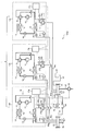
- FIG. 2 is a circuit diagram showing a configuration example of the heat source system shown in FIG.
- FIG. 2 shows a case where each of the pumps 21a to 21c shown in FIG. 1 is provided in each of the heat source devices 10a to 10c. Since the heat source units 10a to 10c have the same configuration, the configuration of the heat source unit 10a will be mainly described in detail here, and the description of the heat source units 10b and 10c will be omitted.
- the heat source device 10a includes a compressor 11, a four-way valve 16, an air heat exchanger 12, a fan 13, an expansion valve 14, a water heat exchanger 15, and a control device 17a.
- the refrigerant circuit 18 includes a compressor 11, a four-way valve 16, an air heat exchanger 12, and an expansion valve 14.
- the water heat exchanger 15 is connected to the refrigerant circuit 18.
- one of the two connection ports is connected to the suction port of the compressor 11 and the other is connected to the discharge port of the compressor 11.
- one connection port is connected to the other connection port via the air heat exchanger 12, the expansion valve 14, and the water heat exchanger 15.
- Compressor 11 compresses and discharges refrigerant to be sucked.
- the air heat exchanger 12 performs heat exchange between air and the refrigerant.
- the four-way valve 16 switches the refrigerant flow path.
- the fan 13 supplies outside air to the air heat exchanger 12.
- the expansion valve 14 adjusts the pressure of the refrigerant to expand the refrigerant.
- the water heat exchanger 15 sends the water supplied from the return water header pipe 23 to the outgoing header pipe 22 after exchanging heat with the refrigerant.
- Water pipes 55 a and 54 a are connected to the water heat exchanger 15.
- the water heat exchanger 15 is connected to the pump 21a through a water pipe 54a.
- the pump 21a is provided with an inverter circuit 24a for controlling the operating frequency.
- the pump 21a operates in a range where the operation frequency is the rated frequency.
- the maximum value is referred to as the maximum frequency
- the minimum value is referred to as the minimum frequency.
- An outlet pressure sensor 41a that measures the water pressure and a temperature sensor 43a that measures the temperature of the water are provided in the water pipe 55a on the water outlet side of the water heat exchanger 15.
- An inlet pressure sensor 42a for measuring the water pressure is provided in the water pipe 54a on the water inlet side of the water heat exchanger 15.
- FIG. 3 is a diagram illustrating a configuration example of each control device provided in the plurality of heat source units illustrated in FIG. 2.
- each of the control devices 17a to 17c includes a memory 71 that stores a program, and a CPU (Central Processing Unit) 72 that executes processing according to the program.
- a CPU Central Processing Unit
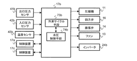
- FIG. 4 is a functional block diagram showing a configuration example of a control device provided in one heat source machine among the plurality of heat source machines shown in FIG.
- FIG. 4 is a functional block diagram illustrating a configuration example of the control device 17a provided in the heat source device 10a.
- the control device 17a is connected to the compressor 11, the four-way valve 16, the expansion valve 14, and the fan 13 through signal lines.
- the control device 17a is connected to the outlet pressure sensor 41a, the inlet pressure sensor 42a, the temperature sensor 43a, the bypass valve 32, the differential pressure gauge 34, and the inverter circuit 24a via signal lines.
- the control device 17a is connected to the control device 17b provided in the heat source device 10b and the control device 17c provided in the heat source device 10c through signal lines.
- the control device 17a includes refrigeration cycle means 73a, water pressure control means 74a, and number control means 75.
- the refrigeration cycle means 73a, the water pressure control means 74a, and the number control means 75 are configured in the control device 17a.
- the memory 71 of the control device 17 a stores information on the target range of the water pressure difference between the return water header pipe 23 and the outgoing water header pipe 22.
- the target range is an allowable range with respect to the water pressure difference on the basis of the determined target value.
- the memory 71 stores information indicating the relationship between the water pressure difference before and after the water heat exchanger 15, the flow rate of the pump 21a, and the operating frequency.
- the control device 17a transmits information on the operation state to the control devices 17b and 17c when an instruction for any one of the cooling operation and the heating operation is input.
- the control device 17a receives information on the operating frequency of the compressor 11 from the control devices 17b and 17c.
- the control device 17a receives the measured values of the temperature sensors 43b and 43c from the control devices 17b and 17c at a constant cycle.
- the control device 17a receives the measured values of the outlet pressure sensors 41b and 41c and the measured values of the inlet pressure sensors 42b and 42c from the control devices 17b and 17c at regular intervals.
- the number control means 75 estimates the amount of heat generated by each refrigerant circuit 18 of the heat source units 10a to 10c from the operating frequency of each compressor 11 of the heat source units 10a to 10c.
- the number control means 75 determines the number of heat source devices to be operated among the heat source devices 10a to 10c from the estimated heat amount and the heat amount necessary for the load.
- the number control means 75 determines the flow rate required for the pump connected to the heat source machine to be operated from the measured values of the temperature sensors 43a to 43c, the outlet pressure sensors 41a to 41c, and the inlet pressure sensors 42a to 42c. calculate. Then, the number control means 75 transmits the operation instruction information including the operation instruction of the heat source apparatus, the operation instruction of the pump, and the information of the target flow rate of the pump to the control device provided in the heat source apparatus to be operated. .
- the refrigeration cycle means 73 a controls the refrigeration cycle in the refrigerant circuit 18.
- the refrigeration cycle means 73a receives an operation instruction from the number control means 75, the refrigeration cycle means 73a switches the flow path of the four-way valve 16 corresponding to the operation state including the cooling operation and the heating operation.
- the refrigeration cycle means 73a controls the operating frequency of the compressor 11 and the fan 13 and the opening degree of the expansion valve 14 so that the water temperature measured by the temperature sensor 43a matches the target temperature.
- the water pressure control means 74a When the water pressure control means 74a receives the operation instruction of the pump 21a from the number control means 75, the water pressure control means 74a obtains the water pressure difference from the measured values of the outlet pressure sensor 41a and the inlet pressure sensor 42a. The water pressure control means 74a calculates the flow rate from the obtained water pressure difference, and controls the operating frequency of the pump 21a via the inverter circuit 24a so that the calculated flow rate becomes the target flow rate.
- the water pressure control means 74a controls the operation frequency of the pump connected to the heat source machine to be operated and the opening degree of the bypass valve 32 so that the water pressure difference acquired from the differential pressure gauge 34 falls within the target range.
- the water pressure control means 74a determines whether or not the operating frequency of the pump being operated is the lowest frequency when performing water pressure control of the bypass pipe 31. As a result of the determination, when the pump operating frequency is not the lowest frequency, the water pressure control means 74a controls the opening degree of the bypass valve 32 to finely adjust the water pressure difference of the bypass pipe 31. As a result of the determination, when the operation frequency of the pump is the lowest frequency, the water pressure control means 74a determines whether or not the opening degree of the bypass valve 32 is the minimum opening degree.
- the water pressure control means 74a controls the operating frequency of the pump to finely adjust the water pressure difference of the bypass pipe 31.
- the water pressure control means 74a controls the opening degree of the bypass valve 32 to thereby reduce the water pressure difference of the bypass pipe 31. Fine tune.
- FIG. 5 is a functional block diagram illustrating a configuration example of a control device provided in a heat source device different from the heat source device provided with the control device illustrated in FIG. 4. Since the control devices 17b and 17c have the same configuration, the configuration of the control device 17b will be described here.
- the control device 17b is connected to the compressor 11, the four-way valve 16, the expansion valve 14, and the fan 13 through signal lines.
- the control device 17a is connected to the outlet pressure sensor 41b, the inlet pressure sensor 42b, the temperature sensor 43b, and the inverter circuit 24b via signal lines.
- the control device 17b is connected to the control devices 17a and 17c through signal lines.
- Control device 17b has refrigeration cycle means 73b and water pressure control means 74b.
- the refrigeration cycle means 73b and the water pressure control means 74b are configured in the control device 17b.
- the memory 71 of the control device 17b stores information indicating the relationship between the water pressure difference before and after the water heat exchanger 15 and the flow rate and operating frequency of the pump 21b.
- the control device 17b transmits the measured value of the temperature sensor 43b to the control device 17a at a constant cycle.
- the control device 17b transmits the measured values of the outlet pressure sensor 41b and the inlet pressure sensor 42b to the control device 17a at a constant cycle.
- the control device 17b transmits information on the operating frequency of the compressor 11 to the control device 17a.
- the refrigeration cycle means 73b controls the refrigeration cycle of the refrigerant circuit 18 in the same manner as the refrigeration cycle means 73a when receiving an operation instruction for the heat source device 10b from the control device 17a.
- the water pressure control means 74b receives an operation instruction of the pump 21b from the control device 17a
- the water pressure control means 74b obtains a water pressure difference from the measured values of the outlet pressure sensor 41b and the inlet pressure sensor 42b.
- the water pressure control means 74b calculates the flow rate from the obtained water pressure difference, and controls the operating frequency of the pump 21b via the inverter circuit 24b so that the calculated flow rate becomes the target flow rate.
- control devices 17a to 17c are provided in the heat source devices 10a to 10c, respectively.
- one control device may be provided.
- the control device 17a may have the functions of the control devices 17b and 17c.
- FIG. 6 is a flowchart showing an operation procedure of the heat source system according to Embodiment 1 of the present invention.
- the control device 17a determines the number of heat source devices to be operated among the heat source devices 10a to 10c based on the amount of heat necessary for the load. Specifically, the control device 17a estimates the amount of heat that can be generated by each refrigerant circuit 18 of the heat source devices 10a to 10c from the operating frequency of each compressor 11. Then, the control device 17a determines the number of heat source devices to be operated among the heat source devices 10a to 10c from the estimated heat amount and the heat amount necessary for the load. Then, the control device 17a operates a pump connected to the operating heat source machine among the pumps 21a to 21c.
- the control device 17a controls the operating frequency of the compressor 11 so that the measured value of the temperature sensor 43a becomes the target temperature. After determining the number of operating heat source units, the control device 17a determines the number of operating heat source units when the estimated amount of heat is less than the amount of heat necessary for the load based on the measured value obtained from the temperature sensor 43a. May increase.
- the control device 17a determines whether or not the operation frequency of the pump 21a is the lowest frequency as follows (step S102).
- the control device 17a calculates the water pressure difference from the measured values of the outlet pressure sensor 41a and the inlet pressure sensor 42a, and calculates the water flow rate of the heat source device 10a alone from the calculated water pressure difference. Subsequently, the control device 17a determines whether or not the calculated water flow rate is the lower limit value of the flow rate range of the heat source device 10a. When the water flow rate is the lower limit value of the flow rate range of the heat source device 10a, the control device 17a determines that the operation frequency of the pump 21a is the lowest frequency.
- control device 17a may determine whether or not the water flow rate is the lower limit value of the flow rate range of the heat source device 10a based on the characteristics of the pump 21a. As a result of the determination, when the water flow rate is the lower limit value of the flow rate range of the heat source device 10a, the control device 17a determines that the frequency of the pump 21a is the lowest frequency. In this case, the memory 71 of the control device 17a stores the flow rate range of the water flowing through the water heat exchangers 15 of the heat source units 10a to 10c and the characteristics of the pumps 21a to 21c.
- step S102 the control device 17a selects either the operating frequency of the pump 21a or the opening degree of the bypass valve 32 as means for finely adjusting the water pressure difference between the outgoing water side and the returning water side. To do.
- step S103 determines whether or not the opening degree of the bypass valve 32 is the minimum opening degree. As a result of the determination in step S103, when the opening degree of the bypass valve 32 is the minimum opening degree, the control device 17a maintains the opening degree of the bypass valve 32 at the minimum opening degree, and the value of the differential pressure gauge 34 enters the target range. In this manner, the frequency of the pump 21a is controlled (step S104).
- the control device 17a finely adjusts the water pressure difference of the bypass pipe 31 using the operating frequency of the pump 21a.
- the opening degree of the bypass valve 32 has a higher sensitivity than the operating frequency of the pump with respect to the water pressure difference between the outgoing water side and the return water side.
- the opening degree of the bypass valve 32 is the minimum opening degree and the operating frequency of the pump 21a is the lowest frequency, the balance between the water pressure on the outgoing water side and the water pressure on the return water side is almost maintained. it is conceivable that. In this state, in order to prevent the balance from being disturbed as much as possible, an operating frequency of the pump 21a having a sensitivity smaller than the opening degree of the bypass valve 32 is selected as a means for adjusting the water pressure difference.
- step S106 the control device 17a maintains the operation frequency of the pump 21a and sets the bypass valve 32 so that the value of the differential pressure gauge 34 falls within the target range. Control is performed (step S106).
- the control device 17a controls the opening degree of the bypass valve 32 that is highly sensitive to the water pressure difference between the outgoing water side and the return water side, thereby making the water pressure difference smoother. Can be adjusted.
- step S106 when the control device 17a adjusts the water pressure difference between the outgoing water side and the return water side with the operating frequency of the pump, the operating frequency of the pump may increase. In this case, the flow rate of water flowing through the load increases.
- step S106 by selecting the opening degree of the bypass valve 32 as a means for adjusting the water pressure difference, an increase in the operating frequency of the pump can be suppressed and an increase in power consumption can be suppressed.
- step S103 when the opening degree of the bypass valve 32 is not the minimum opening degree, the control device 17a maintains the operation frequency of the pump 21a at the lowest frequency so that the value of the differential pressure gauge 34 falls within the target range. Then, the opening degree of the bypass valve 32 is controlled (step S105).
- the operating frequency of the pump is the lowest frequency, the flow rate of water supplied to the load is small, and when the controller 17a adjusts the opening degree of the bypass valve 32, the water pressure difference between the outgoing water side and the return water side is It is thought that it will change greatly. However, even if the control device 17a attempts to control the operation frequency of the pump, the flow rate of water cannot be reduced.
- step S105 the bypass valve 32 having room for fine adjustment in the direction of decreasing the water pressure difference is selected as a means for adjusting the water pressure difference between the outgoing water side and the return water side.
- the number of necessary heat source units is determined from the amount of heat generated by the heat source units 10a to 10c and the necessary amount of heat, and the operating frequency of the pump connected to the operating heat source unit is rated. It is determined whether or not it is the lowest frequency. Then, as a result of the determination, the heat source system 100 controls either the operating frequency of the pump or the opening of the bypass valve 32 so that the water pressure difference between the outgoing water side and the return water side falls within the target range. .
- the pump operating frequency is used as a means for adjusting the water pressure difference between the outgoing water side and the return water side according to the determination result of whether or not the operating frequency of the pump is the lowest frequency.
- One of the opening degrees of the bypass valve 32 is selected. As a result, it is possible to finely adjust the water pressure difference between the outgoing water side and the return water side.
- the heat source system 100 maintains the pump operating frequency when the pump operating frequency is not the lowest frequency, and the water pressure difference between the outgoing water side and the return water side falls within the target range.
- the opening degree of the bypass valve 32 is controlled.
- the heat source system 100 controls the opening degree of the bypass valve 32 that is highly sensitive to the water pressure difference between the outgoing water side and the return water side, thereby smoothing the water pressure difference more smoothly. Can be adjusted. Further, by selecting the opening degree of the bypass valve 32 as the means for adjusting the water pressure difference, it is possible to suppress an increase in the operating frequency of the pump and an increase in power consumption.
- the heat source system 100 When the pump operating frequency is the lowest frequency and the opening degree of the bypass valve 32 is the minimum opening degree, the heat source system 100 is used so that the water pressure difference between the outgoing water side and the return water side is within the target range. Control the operating frequency of the pump to enter. In this case, a state where the balance between the water pressure on the outgoing water side and the water pressure on the return water side is almost maintained is maintained, and the balance can be prevented from being disturbed as much as possible.
- the heat source system 100 maintains the operating frequency of the pump at the lowest frequency,
- the opening degree of the bypass valve 32 is controlled so that the water pressure difference falls within the target range.
- the opening degree of the bypass valve 32 does not reach the minimum opening degree, there is room for fine adjustment of the opening degree of the bypass valve 32. Therefore, as a means for adjusting the water pressure difference between the outgoing water side and the return water side, it is possible to select the bypass valve 32 that has room for fine adjustment to reduce the water pressure difference.
- Embodiment 2 a water switch connected to a load is provided with a flow switch.
- FIG. 7 is a circuit diagram showing a configuration example of the heat source system according to the second embodiment of the present invention. In the second embodiment, detailed description of the same configuration as that of the first embodiment is omitted.
- the flow switch 35 is provided in the water pipe 52 connected to the return water header pipe 23 as compared with the configuration shown in FIG. .
- the flow switch 35 is connected to the control device 17a by a signal line.
- the flow switch 35 outputs a detection signal indicating whether or not water is flowing through the water pipe 52.
- the flow switch 35 When water is flowing through the water pipe 52, the flow switch 35 outputs an off signal detection signal to the control device 17a.
- the flow switch 35 When water does not flow through the water pipe 52, the flow switch 35 outputs an ON signal detection signal to the control device 17a.
- the number control means 75 stops the operation of the compressor 11 of the heat source devices 10a to 10c.
- the number control means 75 operates one of the pumps 21a to 21c and stops the other pumps. At that time, the number control means 75 may set the operation frequency of the pump to be operated to the lowest frequency.
- the water pressure control means 74a controls the opening degree of the bypass valve 32 so that the water pressure difference measured by the differential pressure gauge 34 falls within the target range.
- FIG. 8 is a flowchart showing an operation procedure of the heat source system according to Embodiment 2 of the present invention. Steps S101 to S106 shown in FIG. 8 are the same as the processing described with reference to FIG.
- the control device 17a determines whether the detection signal acquired from the flow switch 35 is in an on state or an off state at a constant cycle (step S201). As a result of the determination, if the detection signal is in the off state, the control device 17a proceeds to step S101. On the other hand, if the result of determination in step S201 is that the detection signal is on, the control device 17a stops the operation of the compressor 11 of the heat source devices 10a to 10c, and turns on one of the pumps 21a to 21c. The other pump is stopped by operating (step S202). Subsequently, the control device 17a sets the operating frequency of one operating pump to the lowest frequency. Further, the control device 17a controls the opening degree of the bypass valve 32 so that the water pressure difference measured by the differential pressure gauge 34 falls within the target range (step S203).
- the heat source units 10a to 10c are stopped, the pump is operated in one unit, and the water pipe The water is circulated between the load and the heat source units 10a to 10c via the.
- the compressors 11 of the heat source units 10a to 10c are stopped, so that power consumption is suppressed.
- Embodiment 3 FIG. In the third embodiment, the position where the differential pressure gauge 34 is provided is different from that in the first embodiment.
- FIG. 9 is a circuit diagram showing a configuration example of the heat source system according to the third embodiment of the present invention. In the third embodiment, detailed description of the same configuration as that of the first embodiment is omitted.
- the distance from the heat source units 10a to 10c among the plurality of fan coil units 60a and 60b is farthest from the configuration shown in FIG.
- a differential pressure gauge 34 is provided in the fan coil unit 60b.
- the distance of the fan coil unit 60b is larger than the distance of the fan coil unit 60a. .
- the differential pressure gauge 34 is connected in parallel to the fan coil unit 60b.
- the differential pressure gauge 34 measures the water pressure difference between the outgoing header pipe 22 side of the heat exchanger 61 and the return water header pipe 23 side of the on-off valve 63.
- the operation of the heat source system 100b according to the third embodiment is the same as the operation described with reference to FIG. 6 in the first embodiment, and thus detailed description thereof is omitted.
- the load that is the farthest from the heat source devices 10a to 10c has a slower flow of supplied water than the other loads. Therefore, at the load farthest from the heat source devices 10a to 10c, the water pressure difference between the outgoing header side and the return water header side becomes the smallest.
- the differential pressure gauge 34 is provided in a load farthest from the heat source devices 10a to 10c among a plurality of loads. Then, the heat source system 100b adjusts the water pressure difference between the outgoing water side and the return water side so that the measured value of the differential pressure gauge 34 falls within the target range.
- the water pressure difference between the outgoing water side and the return water side enters the target range, and a sufficient amount of water is supplied. Furthermore, a sufficient amount of water is supplied to a load that is closer to the load farthest from the heat source devices 10a to 10c.
- Embodiment 4 FIG.
- the fourth embodiment is a combination of the second embodiment and the third embodiment.
- FIG. 10 is a circuit diagram showing a configuration example of a heat source system according to Embodiment 4 of the present invention.
- FIG. 10 detailed description of the same configuration as in the first to third embodiments is omitted.
- the flow switch 35 is provided in the water pipe 52 connected to the return water header pipe 23 as compared with the configuration shown in FIG. Further, in the heat source system 100c of the fourth embodiment, compared to the configuration shown in FIG. 1, among the plurality of fan coil units 60a and 60b, the fan coil unit 60b that is the farthest away from the heat source units 10a to 10c is used. A differential pressure gauge 34 is provided.
- the operation of the heat source system 100c according to the fourth embodiment is the same as the operation described with reference to FIG. 8 in the second embodiment, and thus detailed description thereof is omitted.
- the heat source devices 10a to 10c are stopped and The pump is operated to circulate water. According to the fourth embodiment, not only the same effects as those of the first embodiment but also the respective effects of the second and third embodiments can be obtained.
- Refrigeration cycle device 10a-10c heat source machine, 11 compressor, 12 air heat exchanger, 13 fan, 14 expansion valve, 15 water heat exchanger, 16 four-way valve, 17a-17c control device, 18 refrigerant circuit, 20 return Water header pipe, 21a-21c pump, 22 outgoing header pipe, 23 return water header pipe, 24a-24c inverter circuit, 25 return water header pipe, 31 bypass pipe, 32 bypass valve, 33 tank, 34 differential pressure gauge, 35 flow Switch, 41a-41c outlet pressure sensor, 42a-42c inlet pressure sensor, 43a-43c temperature sensor, 51-53, 54a-54c, 55a-55c water piping, 60, 60a, 60b fan coil unit, 61 heat exchanger, 62 fan, 63 on-off valve, 71 memory, 72 CPU 73a, 73b refrigeration cycle means, 74a, 74b pressure control means, 75 volume control means, 100,100a ⁇ 100c heat source system.
Landscapes
- Engineering & Computer Science (AREA)
- Mechanical Engineering (AREA)
- General Engineering & Computer Science (AREA)
- Chemical & Material Sciences (AREA)
- Combustion & Propulsion (AREA)
- Physics & Mathematics (AREA)
- Thermal Sciences (AREA)
- Life Sciences & Earth Sciences (AREA)
- Sustainable Development (AREA)
- Air Conditioning Control Device (AREA)
- Other Air-Conditioning Systems (AREA)
Abstract
熱源システムは、水熱交換器を含む冷媒回路を有する複数の熱源機と、複数の水熱交換器から流入する水を合流して負荷に供給する往水ヘッダ管と、負荷から流入する水を複数の水熱交換器に分流する還水ヘッダ管と、複数の水熱交換器に水を送り出す複数のポンプと、往水ヘッダ管と還水ヘッダ管とを接続するバイパス配管と、バイパス配管に設けられたバイパス弁と、負荷に供給される水の圧力と負荷から戻る水の圧力との水圧差を測定する差圧計と、複数の熱源機および複数のポンプを制御する制御装置とを有し、制御装置は、複数の冷媒回路が生成する熱量と必要な熱量とから、複数の熱源機のうち、運転する熱源機の台数を決定し、運転する熱源機に接続されるポンプの運転周波数が最低周波数であるか否かを判定し、判定の結果、水圧差が目標範囲に入るように、ポンプの運転周波数およびバイパス弁の開度のうち、いずれか一方を制御するものである。
Description
本発明は、冷媒回路を循環する冷媒が水を冷却および加熱することで冷水および温水を生成する熱源システムに関する。
水を冷却および加熱して冷水および温水を製造する空冷式ヒートポンプチラーには、熱源機側にポンプが設けられた単式ポンプシステムと、熱源機側だけでなく、往水ヘッダ管にもポンプが設けられた複式ポンプシステムがある。
複式ポンプシステムの一例が特許文献1に開示されている。特許文献1には、運転する熱源機の台数を決定する方法の一例として、往水ヘッダから負荷に供給する水の流量と負荷から還水ヘッダに戻る水の流量とを計測し、これらの流量の差に応じて増減する方法が記載されている。また、特許文献1には、往水1次ヘッダに圧力センサを設け、圧力センサの測定値を用いて、熱源機の台数制御を行うことが開示されている。さらに、特許文献1には、往水側と還水側との水圧差の調節するために、往水1次ヘッダに設けられた圧力センサの測定値を用いて、バイパス弁の開度を制御することが開示されている。
特許文献1に開示された熱源制御システムでは、システムを設置する際に、往水1次ヘッダに圧力センサを現地で取り付ける工事が必要になる。その結果、作業者が圧力センサを往水1次ヘッダに取り付けるための作業スペースが必要になるだけでなく、圧力センサの取り付け作業の分だけシステムの設置費用が高くなってしまう。この問題は、圧力センサの代わりに、負荷に供給する水の流量計と負荷から還水ヘッダに戻る水の流量計とを取り付ける場合にも、起こり得る。
本発明は、上記のような課題を解決するためになされたもので、システムの設置費用を抑制し、往水側と還水側との水圧差を微調節できる熱源システムを提供するものである。
本発明に係る熱源システムは、水熱交換器を含む冷媒回路を有する複数の熱源機と、負荷および複数の前記水熱交換器と水配管で接続され、該複数の水熱交換器から流入する水を合流して該負荷に供給する往水ヘッダ管と、前記負荷および前記複数の水熱交換器と水配管で接続され、該負荷から流入する水を該複数の水熱交換器に分流する還水ヘッダ管と、前記複数の水熱交換器と前記還水ヘッダ管とを接続する水配管に設けられ、前記複数の水熱交換器に水を送り出す複数のポンプと、前記往水ヘッダ管と前記還水ヘッダ管とを接続するバイパス配管と、前記バイパス配管に設けられたバイパス弁と、前記往水ヘッダ管から前記負荷に供給される水の圧力と該負荷から前記還水ヘッダ管に戻る水の圧力との水圧差を測定する差圧計と、前記複数の熱源機および前記複数のポンプを制御する制御装置と、を有し、前記制御装置は、前記複数の冷媒回路が生成する熱量と必要な熱量とから、前記複数の熱源機のうち、運転する熱源機の台数を決定する台数制御手段と、前記台数制御手段が決定した熱源機に接続される前記ポンプの運転周波数が定格周波数の最低周波数であるか否かを判定し、判定の結果、前記水圧差が目標範囲に入るように、該ポンプの運転周波数および前記バイパス弁の開度のうち、いずれか一方を制御する水圧制御手段と、を有するものである。
本発明によれば、往水側と還水側との水圧差の調節手段として、ポンプの運転周波数およびバイパス弁の開度のうち、いずれかを選択できるだけでなく、運転する熱源機の台数が必要な熱量から決定されるため、余分なセンサを設ける必要がない。その結果、システムの設置費用を抑制し、往水側と還水側との水圧差を微調節できる。
実施の形態1.
本実施の形態1の熱源システムの構成を説明する。図1は、本発明の実施の形態1にかかる熱源システムの一構成例を示す模式図である。本実施の形態1では、熱源機側にポンプが設けられた単式ポンプシステムの場合で説明する。
本実施の形態1の熱源システムの構成を説明する。図1は、本発明の実施の形態1にかかる熱源システムの一構成例を示す模式図である。本実施の形態1では、熱源機側にポンプが設けられた単式ポンプシステムの場合で説明する。
図1に示す熱源システム100は、冷凍サイクル装置1と、往水ヘッダ管22と、還水ヘッダ管20と、タンク33とを有する。冷凍サイクル装置1は、空冷式ヒートポンプチラーの一例である。冷凍サイクル装置1は、複数の熱源機10a~10cを有する。熱源機10a~10cのそれぞれは往水ヘッダ管22および還水ヘッダ管20を介して負荷と接続されている。
熱源機10a~10cのそれぞれは、水配管55a~55cのそれぞれを介して、往水ヘッダ管22と接続されている。また、熱源機10a~10cのそれぞれは、水配管54a~54cを介しで、還水ヘッダ管20と接続されている。水配管54aには、水を還水ヘッダ管23から熱源機10aに送り出すポンプ21aが設けられている。水配管54bには、水を還水ヘッダ管23から熱源機10bに送り出すポンプ21bが設けられている。水配管54cには、水を還水ヘッダ管23から熱源機10cに送り出すポンプ21cが設けられている。
還水ヘッダ管20は、熱源機10a~10cと接続される還水ヘッダ管23と、負荷と接続される還水ヘッダ管25とを有する。還水ヘッダ管23および還水ヘッダ管25は水配管51で接続されている。還水ヘッダ管23には、水を溜めるタンク33が水配管53を介して接続されている。タンク33は開放型タンクである。往水ヘッダ管22は、水配管55a~55cから流入する水を合流して負荷に供給する。還水ヘッダ管23は、負荷から流入する水を水配管54a~54cに分流する。
負荷は、図1に示す構成例では、2台のファンコイルユニット60である。ファンコイルユニット60は、往水ヘッダ管22と還水ヘッダ管25とを接続する水配管52に設けられている。ファンコイルユニット60は、熱交換器61、ファン62および開閉弁63を有する。開閉弁63は2方弁である。往水ヘッダ管22から水配管52を介してファンコイルユニット60に流入した水は、熱交換器61において空気との間で熱交換を行った後、水配管52を介して還水ヘッダ管25に戻る。
還水ヘッダ管23と往水ヘッダ管22とはバイパス配管31で接続されている。バイパス配管31には、還水ヘッダ管23の水圧と往水ヘッダ管22の水圧との差圧を調整するバイパス弁32が設けられている。バイパス弁32は、開状態と閉状態とを有する。開状態の場合、バイパス弁32は、最大開度と最小開度の範囲で、開度の大きさを変えることができる。還水ヘッダ管23および往水ヘッダ管22の間には、バイパス配管31と並列に差圧計34が設けられている。差圧計34は、往水ヘッダ管22から負荷に供給される水と負荷から還水ヘッダ管20に戻る水との水圧差を測定する。
なお、本実施の形態1では、冷凍サイクル装置1が3台の熱源機10a~10cを有する場合で説明するが、熱源機の台数は2台以上であればよく、3台に限らない。また、本実施の形態1では、負荷がファンコイルユニット60の場合で説明するが、負荷はファンコイルユニット60に限らない。負荷はエアハンドリングユニットであってもよい。負荷の数は2つの場合に限らない。ポンプ21a~21cは、水配管を循環する水が流れる方向を基準として、熱源機10a~10cの下流側に設けられていればよく、ポンプ21a~21cの位置は図1に示す場合に限らない。ポンプ21a~21cのそれぞれは熱源機10a~10cのそれぞれに設けられていてもよい。
さらに、図1では、差圧計34は、還水ヘッダ管23と往水ヘッダ管22との間に設けられているが、差圧計34の位置は図1に示す場合に限らない。差圧計34が往水ヘッダ管22から負荷に供給される水と負荷から還水ヘッダ管20に戻る水との水圧差を計測できる位置であれば、差圧計34の位置は、図1に示した位置でなくてもよい。図1は、還水ヘッダ管20が還水ヘッダ管23および25を有する場合の構成を示しているが、還水ヘッダ管25が設けられていなくてもよい。
次に、図1に示した熱源機10a~10cの構成を詳しく説明する。図2は、図1に示した熱源システムの一構成例を示す回路図である。図2は、図1に示したポンプ21a~21cのそれぞれが熱源機10a~10cのそれぞれに設けられている場合を示す。熱源機10a~10cは同様な構成のため、ここでは、主に熱源機10aの構成を詳細に説明し、熱源機10bおよび10cの説明を省略する。
熱源機10aは、圧縮機11と、四方弁16と、空気熱交換器12と、ファン13と、膨張弁14と、水熱交換器15と、制御装置17aとを有する。冷媒回路18は、圧縮機11、四方弁16、空気熱交換器12、および膨張弁14を有する。水熱交換器15は冷媒回路18と接続されている。四方弁16に設けられた4つの接続口のうち、2つの接続口の一方が圧縮機11の吸入口に接続され、他方が圧縮機11の吐出口に接続されている。残りの2つの接続口のうち、一方の接続口が空気熱交換器12、膨張弁14および水熱交換器15を介して、他方の接続口に接続されている。
圧縮機11は、吸入する冷媒を圧縮して吐出する。空気熱交換器12は、空気と冷媒との間で熱交換を行う。四方弁16は、冷媒の流路を切り替える。ファン13は、外気を空気熱交換器12に供給する。膨張弁14は、冷媒の圧力を調節し、冷媒を膨張させる。水熱交換器15は、還水ヘッダ管23から供給される水を冷媒との間で熱交換した後に往水ヘッダ管22に送出する。
水熱交換器15には、水配管55aおよび54aが接続されている。水熱交換器15は、水配管54aを介してポンプ21aと接続されている。ポンプ21aには、運転周波数を制御するインバータ回路24aが設けられている。ポンプ21aは、運転周波数が定格周波数の範囲で運転する。以下では、定格周波数の範囲において、最大値を最大周波数と称し、最小値を最低周波数と称する。水熱交換器15の水の出口側の水配管55aに、水圧を測定する出口圧力センサ41aと、水の温度を測定する温度センサ43aとが設けられている。水熱交換器15の水の入口側の水配管54aに、水圧を測定する入口圧力センサ42aが設けられている。
図3は、図2に示した複数の熱源機に設けられた各制御装置の一構成例を示す図である。図3に示すように、制御装置17a~17cは、プログラムを記憶するメモリ71と、プログラムにしたがって処理を実行するCPU(Central Processing Unit)72とを有する。
図4は、図2に示した複数の熱源機のうちの1つの熱源機に設けられた制御装置の一構成例を示す機能ブロック図である。図4は、熱源機10aに設けられた制御装置17aの構成例を示す機能ブロック図である。
制御装置17aは、圧縮機11、四方弁16、膨張弁14およびファン13と信号線で接続されている。また、制御装置17aは、出口圧力センサ41a、入口圧力センサ42a、温度センサ43a、バイパス弁32、差圧計34およびインバータ回路24aと、信号線を介して接続されている。制御装置17aは、熱源機10bに設けられた制御装置17bおよび熱源機10cに設けられた制御装置17cと信号線で接続されている。
制御装置17aは、冷凍サイクル手段73aと、水圧制御手段74aと、台数制御手段75とを有する。CPU72がプログラムにしたがって処理を実行することで、冷凍サイクル手段73a、水圧制御手段74aおよび台数制御手段75が制御装置17aに構成される。制御装置17aのメモリ71は、還水ヘッダ管23と往水ヘッダ管22との水圧差の目標範囲の情報を記憶している。目標範囲は、水圧差に関して、決められた目標値を基準として、許容される範囲である。メモリ71は、水熱交換器15の前後の水圧差と、ポンプ21aの流量および運転周波数との関係を示す情報を記憶している。
制御装置17aは、冷房運転および暖房運転のうち、いずれかの運転状態の指示が入力されると、運転状態の情報を制御装置17bおよび17cに送信する。制御装置17aは、圧縮機11の運転周波数の情報を制御装置17bおよび17cから受信する。制御装置17aは、温度センサ43bおよび43cの測定値を制御装置17bおよび17cから、一定の周期で受信する。制御装置17aは、出口圧力センサ41bおよび41cの測定値と、入口圧力センサ42bおよび42cの測定値とを制御装置17bおよび17cから、一定間毎に受信する。
台数制御手段75は、熱源機10a~10cの各圧縮機11の運転周波数から、熱源機10a~10cの各冷媒回路18が生成する熱量を推算する。台数制御手段75は、推算した熱量と負荷に必要な熱量とから、熱源機10a~10cのうち、運転対象の熱源機の台数を決定する。また、台数制御手段75は、温度センサ43a~43c、出口圧力センサ41a~41cおよび入口圧力センサ42a~42cの各センサの測定値から、運転対象の熱源機に接続されたポンプに必要な流量を算出する。そして、台数制御手段75は、運転対象の熱源機に設けられた制御装置に対して、熱源機の運転指示と、ポンプの運転指示およびポンプの目標流量の情報とを含む運転指示情報を送信する。
冷凍サイクル手段73aは、冷媒回路18における冷凍サイクルを制御する。冷凍サイクル手段73aは、台数制御手段75から運転の指示を受け付けると、冷房運転および暖房運転を含む運転状態に対応して、四方弁16の流路を切り替える。冷凍サイクル手段73aは、温度センサ43aが測定する水温が目標温度に一致するように、圧縮機11およびファン13の運転周波数と、膨張弁14の開度とを制御する。
水圧制御手段74aは、台数制御手段75からポンプ21aの運転の指示を受け付けると、出口圧力センサ41aおよび入口圧力センサ42aの測定値から水圧差を求める。水圧制御手段74aは、求めた水圧差から流量を算出し、算出した流量が目標流量になるように、インバータ回路24aを介してポンプ21aの運転周波数を制御する。
また、水圧制御手段74aは、差圧計34から取得する水圧差が目標範囲に入るように、運転対象の熱源機に接続されるポンプの運転周波数とバイパス弁32の開度とを制御する。水圧制御手段74aは、バイパス配管31の水圧制御を行う際、運転中のポンプの運転周波数が最低周波数であるか否かを判定する。判定の結果、ポンプの運転周波数が最低周波数でない場合、水圧制御手段74aは、バイパス弁32の開度を制御して、バイパス配管31の水圧差を微調節する。判定の結果、ポンプの運転周波数が最低周波数である場合、水圧制御手段74aは、バイパス弁32の開度が最小開度であるか否かを判定する。
ポンプの運転周波数が最低周波数であり、かつバイパス弁32の開度が最小開度である場合、水圧制御手段74aは、ポンプの運転周波数を制御して、バイパス配管31の水圧差を微調節する。一方、ポンプの運転周波数が最低周波数であるが、バイパス弁32の開度が最小開度でない場合、水圧制御手段74aは、バイパス弁32の開度を制御して、バイパス配管31の水圧差を微調節する。
続いて、制御装置17bおよび制御装置17cの構成を説明する。図5は、図4に示した制御装置が設けられた熱源機とは別の熱源機に設けられた制御装置の一構成例を示す機能ブロック図である。制御装置17bおよび17cは同様な構成であるため、ここでは、制御装置17bの構成を説明する。
制御装置17bは、圧縮機11、四方弁16、膨張弁14およびファン13と信号線で接続されている。また、制御装置17aは、出口圧力センサ41b、入口圧力センサ42b、温度センサ43bおよびインバータ回路24bと、信号線を介して接続されている。制御装置17bは、制御装置17aおよび17cと信号線で接続されている。
制御装置17bは、冷凍サイクル手段73bと、水圧制御手段74bとを有する。CPU72がプログラムにしたがって処理を実行することで、冷凍サイクル手段73bおよび水圧制御手段74bが制御装置17bに構成される。制御装置17bのメモリ71は、水熱交換器15の前後の水圧差と、ポンプ21bの流量および運転周波数との関係を示す情報を記憶している。制御装置17bは、温度センサ43bの測定値を制御装置17aに、一定の周期で送信する。制御装置17bは、出口圧力センサ41bおよび入口圧力センサ42bの測定値を制御装置17aに、一定の周期で送信する。制御装置17bは、圧縮機11の運転周波数の情報を制御装置17aに送信する。
冷凍サイクル手段73bは、熱源機10bの運転指示を制御装置17aから受け付けると、冷凍サイクル手段73aと同様に、冷媒回路18の冷凍サイクルを制御する。水圧制御手段74bは、制御装置17aからポンプ21bの運転の指示を受け付けると、出口圧力センサ41bおよび入口圧力センサ42bの測定値から水圧差を求める。水圧制御手段74bは、求めた水圧差から流量を算出し、算出した流量が目標流量になるように、インバータ回路24bを介してポンプ21bの運転周波数を制御する。
なお、本実施の形態1では、熱源機10a~10cのそれぞれに制御装置17a~17cのそれぞれが設けられている場合で説明したが、制御装置が1台であってもよい。この場合、制御装置17aは、制御装置17bおよび17cの機能を備えていてもよい。
次に、本実施の形態1の熱源システム100の動作を説明する。図6は、本発明の実施の形態1における熱源システムの動作手順を示すフローチャートである。ステップS101において、制御装置17aは、熱源機10a~10cのうち、運転する熱源機の台数を、負荷に必要な熱量を基に決定する。具体的には、制御装置17aは、熱源機10a~10cの各冷媒回路18が生成できる熱量を各圧縮機11の運転周波数から推算する。そして、制御装置17aは、推算した熱量と負荷に必要な熱量とから、熱源機10a~10cのうち、運転する熱源機の台数を決定する。そして、制御装置17aは、ポンプ21a~21cのうち、運転する熱源機に接続されたポンプを運転させる。
以下では、運転対象の熱源機が熱源機10aである場合で説明する。制御装置17aは、温度センサ43aの測定値が目標温度になるように、圧縮機11の運転周波数を制御する。制御装置17aは、熱源機の運転台数を決定した後、温度センサ43aから取得する測定値を基に、推算した熱量が負荷に必要な熱量に満たないと判断した場合、熱源機の運転台数を増やしてもよい。
次に、制御装置17aは、次のようにして、ポンプ21aの運転周波数が最低周波数か否かを判定する(ステップS102)。制御装置17aは、出口圧力センサ41aおよび入口圧力センサ42aの測定値から水圧差を算出し、算出した水圧差から熱源機10a単体の水流量を算出する。続いて、制御装置17aは、算出した水流量が熱源機10aの流量範囲の下限値であるか否かを判定する。水流量が熱源機10aの流量範囲の下限値である場合、制御装置17aは、ポンプ21aの運転周波数が最低周波数であると判定する。
また、制御装置17aは、ポンプ21aの特性を基に、水流量が熱源機10aの流量範囲の下限値であるか否かを判定してもよい。判定の結果、水流量が熱源機10aの流量範囲の下限値である場合、制御装置17aは、ポンプ21aの周波数が最低周波数であると判定する。この場合、制御装置17aのメモリ71は、熱源機10a~10cの各水熱交換器15に流れる水の流量範囲と、ポンプ21a~21cの特性とを記憶している。
ここで、ステップS102において、制御装置17aが、ポンプ21aの運転周波数が最低周波数か否かを判定する理由を説明する。ポンプ21aの運転周波数が最低周波数である場合、負荷に供給される水の流量が少ない状態と考えられる。この場合、バイパス配管31の水圧差を微調節する際、往水側の水圧と還水側の水圧とのバランスが大きく乱れないようにする必要がある。ステップS102において、制御装置17aは、判定の結果、往水側と還水側との水圧差を微調節する手段として、ポンプ21aの運転周波数およびバイパス弁32の開度のうち、いずれかを選択する。
ステップS102の判定の結果、ポンプ21aの運転周波数が最低周波数である場合、制御装置17aは、バイパス弁32の開度が最小開度であるか否かを判定する(ステップS103)。ステップS103の判定の結果、バイパス弁32の開度が最小開度である場合、制御装置17aは、バイパス弁32の開度を最小開度に維持し、差圧計34の値が目標範囲に入るようにポンプ21aの周波数を制御する(ステップS104)。
バイパス弁32の開度が最小開度であり、かつポンプ21aの運転周波数が最低周波数である場合に、制御装置17aがポンプ21aの運転周波数を用いて、バイパス配管31の水圧差を微調節する理由を説明する。往水側と還水側との水圧差に対して、バイパス弁32の開度は、ポンプの運転周波数と比べて、感度が大きい。バイパス弁32の開度が最小開度であり、かつポンプ21aの運転周波数が最低周波数である場合、往水側の水圧と還水側の水圧とのバランスがほとんど保たれた状態になっていると考えられる。この状態では、できるだけバランスを乱さないようにするために、水圧差の調節手段として、バイパス弁32の開度よりも感度の小さい、ポンプ21aの運転周波数が選択される。
一方、ステップS102の判定の結果、ポンプ21aの運転周波数が最低周波数でない場合、制御装置17aは、ポンプ21aの運転周波数を維持し、差圧計34の値が目標範囲に入るようにバイパス弁32を制御する(ステップS106)。ポンプ21aの運転周波数が最低周波数でない場合、負荷に供給される水の流量が少ない状態ではないと考えられる。ある程度の流量が確保された状態では、制御装置17aが、往水側と還水側との水圧差に対して感度の大きいバイパス弁32の開度を制御することで、水圧差をよりスムーズに調節できる。ステップS106で、制御装置17aが往水側と還水側との水圧差をポンプの運転周波数で調節すると、ポンプの運転周波数が増加してしまう場合がある。この場合、負荷に流れる水の流量が増えてしまうことになる。ステップS106において、水圧差の調節手段として、バイパス弁32の開度が選択されることで、ポンプの運転周波数の増加が抑制され、消費電力が増えてしまうことを抑制できる。
また、ステップS103の判定の結果、バイパス弁32の開度が最小開度でない場合、制御装置17aは、ポンプ21aの運転周波数を最低周波数に維持し、差圧計34の値が目標範囲に入るようにバイパス弁32の開度を制御する(ステップS105)。ポンプの運転周波数が最低周波数の場合、負荷に供給される水の流量が少ない状態であり、制御装置17aがバイパス弁32の開度を調節すると、往水側と還水側との水圧差が大きく変化してしまうことが考えられる。しかし、制御装置17aがポンプの運転周波数を制御しようとしても、水の流量を下げることはできない。これに対して、バイパス弁32の開度が最小開度に至っていないので、バイパス弁32の開度を微調節できる余地がある。そのため、ステップS105では、往水側と還水側との水圧差の調節手段として、水圧差を下げる方に微調節する余地があるバイパス弁32が選択される。
本実施の形態1の熱源システム100は、熱源機10a~10cが生成する熱量と必要な熱量とから必要な熱源機の台数を決定し、運転する熱源機に接続されるポンプの運転周波数が定格周波数の最低周波数であるか否かを判定する。そして、熱源システム100は、判定の結果、往水側と還水側との水圧差が目標範囲に入るように、ポンプの運転周波数およびバイパス弁32の開度のうち、いずれか一方を制御する。
本実施の形態1によれば、運転する熱源機の台数が必要な熱量から決定されるため、余分なセンサを設ける必要がない。そのため、熱源システム100の設置時に、作業者が圧力センサまたは流量計を取り付ける工事が不要となり、その作業のための作業スペースも不要となる。また、圧力センサまたは流量計の取り付け作業の分だけ設置費用を削減できるだけでなく、設置工事を短縮化できる。その結果、システムの設置費用を抑制できる。また、本実施の形態1によれば、ポンプの運転周波数が最低周波数であるか否かの判定の結果にしたがって、往水側と還水側との水圧差の調節手段として、ポンプの運転周波数およびバイパス弁32の開度のうち、いずれかが選択される。その結果、往水側と還水側との水圧差の微調節を行うことができる。
バイパス配管31の水圧差の調節を、ポンプの運転周波数を一定にして、バイパス弁32の開度の制御だけで行うことも考えられる。この場合、バイパス弁32の開度を調節しただけで、往水側と還水側の水圧のバランスが大きく乱れてしまう場合がある。
これに対して、本実施の形態1の熱源システム100は、ポンプの運転周波数が最低周波数でない場合、ポンプの運転周波数を維持し、往水側と還水側との水圧差が目標範囲に入るように、バイパス弁32の開度を制御する。ある程度の流量が確保された状態では、熱源システム100が、往水側と還水側との水圧差に対して感度の大きいバイパス弁32の開度を制御することで、水圧差をよりスムーズに調節できる。また、水圧差の調節手段として、バイパス弁32の開度が選択されることで、ポンプの運転周波数の増加が抑制され、消費電力が増えてしまうことを抑制できる。
また、ポンプの運転周波数が最低周波数であり、かつバイパス弁32の開度が最小開度である場合、熱源システム100は、用いて、往水側と還水側との水圧差が目標範囲に入るように、ポンプの運転周波数を制御する。この場合、往水側の水圧と還水側の水圧とのバランスがほとんど保たれた状態が維持され、できるだけバランスを乱さないようにすることができる。
さらに、ポンプの運転周波数が最低周波数であるが、バイパス弁32の開度が最小開度でない場合、熱源システム100は、ポンプの運転周波数を最低周波数に維持し、往水側と還水側との水圧差が目標範囲に入るようにバイパス弁32の開度を制御する。この場合、バイパス弁32の開度が最小開度に至っていないので、バイパス弁32の開度を微調節できる余地がある。そのため、往水側と還水側との水圧差の調節手段として、水圧差を下げる方に微調節する余地のあるバイパス弁32を選択することができる。
実施の形態2.
本実施の形態2は、負荷に接続された水配管にフロースイッチが設けられたものである。
本実施の形態2は、負荷に接続された水配管にフロースイッチが設けられたものである。
本実施の形態2の熱源システムの構成を説明する。図7は、本発明の実施の形態2にかかる熱源システムの一構成例を示す回路図である。本実施の形態2では、実施の形態1と同様な構成についての詳細な説明を省略する。
図7に示すように、本実施の形態2の熱源システム100aには、図2に示した構成と比べると、還水ヘッダ管23に接続された水配管52にフロースイッチ35が設けられている。フロースイッチ35は、制御装置17aと信号線で接続されている。フロースイッチ35は、水配管52に水が流れているか否かを示す検知信号を出力する。水配管52に水が流れている場合、フロースイッチ35は、オフ信号の検知信号を制御装置17aに出力する。水配管52に水が流れていない場合、フロースイッチ35は、オン信号の検知信号を制御装置17aに出力する。
制御装置17aがフロースイッチ35からオン信号を受信した場合、台数制御手段75は、熱源機10a~10cの圧縮機11の運転を停止する。そして、台数制御手段75は、ポンプ21a~21cのうち、1台のポンプを運転して他のポンプを停止させる。その際、台数制御手段75は、運転対象のポンプの運転周波数を最低周波数に設定してもよい。また、制御装置17aがフロースイッチ35からオン信号を受信した場合、水圧制御手段74aは、差圧計34が測定する水圧差が目標範囲に入るようにバイパス弁32の開度を制御する。
次に、本実施の形態2の熱源システム100aの動作を説明する。図8は、本発明の実施の形態2における熱源システムの動作手順を示すフローチャートである。図8に示すステップS101~S106は図6を参照して説明した処理と同様なため、その詳細な説明を省略する。
制御装置17aは、フロースイッチ35から取得する検知信号がオン状態かオフ状態かを一定の周期で判定する(ステップS201)。判定の結果、検知信号がオフ状態である場合、制御装置17aはステップS101に進む。一方、ステップS201の判定の結果、検知信号がオン状態である場合、制御装置17aは、熱源機10a~10cの圧縮機11の運転を停止し、ポンプ21a~21cのうち、1台のポンプを運転して他のポンプを停止させる(ステップS202)。続いて、制御装置17aは、運転している1台のポンプの運転周波数を最低周波数に設定する。また、制御装置17aは、差圧計34が測定する水圧差が目標範囲に入るようにバイパス弁32の開度を制御する(ステップS203)。
本実施の形態2の熱源システム100aは、実施の形態1で説明した構成において、負荷に水が流れていない場合、熱源機10a~10cを停止し、1台にポンプを運転して、水配管を介して負荷と熱源機10a~10cとの間に水を循環させるものである。本実施の形態2によれば、負荷側に水が流れなくなると、熱源機10a~10cの各圧縮機11が停止するため、消費電力が抑制される。
実施の形態3.
本実施の形態3は、差圧計34が設けられる位置が実施の形態1の場合と異なるものである。
本実施の形態3は、差圧計34が設けられる位置が実施の形態1の場合と異なるものである。
本実施の形態3の熱源システムの構成を説明する。図9は、本発明の実施の形態3にかかる熱源システムの一構成例を示す回路図である。本実施の形態3では、実施の形態1と同様な構成についての詳細な説明を省略する。
図9に示すように、本実施の形態3の熱源システム100bでは、図1に示した構成と比べると、複数のファンコイルユニット60aおよび60bのうち、熱源機10a~10cから最も距離が離れたファンコイルユニット60bに差圧計34が設けられている。図9に示す構成例では、ファンコイルユニット60bおよびファンコイルユニット60aと熱源機10a~10cとの間の距離を比較すると、ファンコイルユニット60bの距離の方がファンコイルユニット60aの距離よりも大きい。
差圧計34は、ファンコイルユニット60bに並列に接続されている。差圧計34は、熱交換器61の往水ヘッダ管22側と開閉弁63の還水ヘッダ管23側との水圧差を測定する。
なお、本実施の形態3の熱源システム100bの動作は、実施の形態1において図6を参照して説明した動作と同様になるため、その詳細な説明を省略する。
複数の負荷のうち、熱源機10a~10cから最も距離が遠い負荷では、他の負荷に比べて、供給される水の流れが遅くなる。そのため、熱源機10a~10cから最も距離が遠い負荷において、往水ヘッダ側と還水ヘッダ側との水圧差が最も小さくなる。本実施の形態3の熱源システム100bは、複数の負荷のうち、熱源機10a~10cから最も距離が遠い負荷に差圧計34が設けられている。そして、熱源システム100bは、差圧計34の測定値が目標範囲に入るように、往水側と還水側との水圧差を調節する。そのため、熱源機10a~10cから最も距離が遠い負荷において、往水側と還水側との水圧差が目標範囲に入り、十分な流量の水が供給される。さらに、熱源機10a~10cからの距離が最も遠い負荷よりも近い負荷にも、十分な流量の水が供給されることになる。
実施の形態4.
本実施の形態4は、実施の形態2と実施の形態3とを組み合わせたものである。
本実施の形態4は、実施の形態2と実施の形態3とを組み合わせたものである。
本実施の形態4の熱源システムの構成を説明する。図10は、本発明の実施の形態4にかかる熱源システムの一構成例を示す回路図である。本実施の形態4では、実施の形態1~3と同様な構成についての詳細な説明を省略する。
図10に示すように、本実施の形態4の熱源システム100cでは、図2に示した構成と比べると、還水ヘッダ管23に接続された水配管52にフロースイッチ35が設けられている。また、本実施の形態4の熱源システム100cでは、図1に示した構成と比べると、複数のファンコイルユニット60aおよび60bのうち、熱源機10a~10cから最も距離が離れたファンコイルユニット60bに差圧計34が設けられている。
なお、本実施の形態4の熱源システム100cの動作は、実施の形態2において図8を参照して説明した動作と同様になるため、その詳細な説明を省略する。
本実施の形態4の熱源システム100cは、熱源機10a~10cから最も距離が遠い負荷に差圧計34が設けられ、負荷側に水が流れない場合、熱源機10a~10cを停止し、1台にポンプを運転して水を循環させるものである。本実施の形態4によれば、実施の形態1と同様な効果だけでなく、実施の形態2および3のそれぞれの効果を得ることができる。
1 冷凍サイクル装置、10a~10c 熱源機、11 圧縮機、12 空気熱交換器、13 ファン、14 膨張弁、15 水熱交換器、16 四方弁、17a~17c 制御装置、18 冷媒回路、20 還水ヘッダ管、21a~21c ポンプ、22 往水ヘッダ管、23 還水ヘッダ管、24a~24c インバータ回路、25 還水ヘッダ管、31 バイパス配管、32 バイパス弁、33 タンク、34 差圧計、35 フロースイッチ、41a~41c 出口圧力センサ、42a~42c 入口圧力センサ、43a~43c 温度センサ、51~53、54a~54c、55a~55c 水配管、60、60a、60b ファンコイルユニット、61 熱交換器、62 ファン、63 開閉弁、71 メモリ、72 CPU、73a、73b 冷凍サイクル手段、74a、74b 水圧制御手段、75 台数制御手段、100、100a~100c 熱源システム。
Claims (4)
- 水熱交換器を含む冷媒回路を有する複数の熱源機と、
負荷および複数の前記水熱交換器と水配管で接続され、該複数の水熱交換器から流入する水を合流して該負荷に供給する往水ヘッダ管と、
前記負荷および前記複数の水熱交換器と水配管で接続され、該負荷から流入する水を該複数の水熱交換器に分流する還水ヘッダ管と、
前記複数の水熱交換器と前記還水ヘッダ管とを接続する水配管に設けられ、前記複数の水熱交換器に水を送り出す複数のポンプと、
前記往水ヘッダ管と前記還水ヘッダ管とを接続するバイパス配管と、
前記バイパス配管に設けられたバイパス弁と、
前記往水ヘッダ管から前記負荷に供給される水の圧力と該負荷から前記還水ヘッダ管に戻る水の圧力との水圧差を測定する差圧計と、
前記複数の熱源機および前記複数のポンプを制御する制御装置と、を有し、
前記制御装置は、
前記複数の冷媒回路が生成する熱量と必要な熱量とから、前記複数の熱源機のうち、運転する熱源機の台数を決定する台数制御手段と、
前記台数制御手段が決定した熱源機に接続される前記ポンプの運転周波数が定格周波数の最低周波数であるか否かを判定し、判定の結果、前記水圧差が目標範囲に入るように、該ポンプの運転周波数および前記バイパス弁の開度のうち、いずれか一方を制御する水圧制御手段と、を有する、熱源システム。 - 前記水圧制御手段は、
前記判定の結果、前記ポンプの運転周波数が前記最低周波数でない場合、前記バイパス弁の開度を制御し、前記判定の結果、前記ポンプの運転周波数が前記最低周波数である場合、前記バイパス弁の開度が最小開度であるか否かを判定し、該バイパス弁の開度が最小開度である場合、前記ポンプの運転周波数を制御し、該バイパス弁の開度が最小開度でない場合、該バイパス弁の開度を制御する、請求項1に記載の熱源システム。 - 前記制御装置は、前記負荷に水が流れているか否かを示す検知信号を出力するフロースイッチと接続され、
前記検知信号が前記負荷に水が流れていないことを示している場合、
前記台数制御手段は、前記複数の熱源機の運転を停止し、前記複数のポンプのうち、1台のポンプを運転して他のポンプを停止し、
前記水圧制御手段は、前記水圧差が前記目標範囲に入るように前記バイパス弁の開度を制御する、請求項1または2に記載の熱源システム。 - 前記往水ヘッダ管および前記還水ヘッダ管に複数の前記負荷が並列に接続され、
前記差圧計は、
前記複数の負荷のうち、前記複数の熱源機から最も遠い距離にある負荷と並列に接続されている、請求項1~3のいずれか1項に記載の熱源システム。
Priority Applications (4)
| Application Number | Priority Date | Filing Date | Title |
|---|---|---|---|
| JP2019523297A JP6723450B2 (ja) | 2017-06-08 | 2017-06-08 | 熱源システム |
| PCT/JP2017/021342 WO2018225221A1 (ja) | 2017-06-08 | 2017-06-08 | 熱源システム |
| US16/494,488 US11187439B2 (en) | 2017-06-08 | 2017-06-08 | Heat source system |
| EP17913091.9A EP3637006B1 (en) | 2017-06-08 | 2017-06-08 | Heat source system |
Applications Claiming Priority (1)
| Application Number | Priority Date | Filing Date | Title |
|---|---|---|---|
| PCT/JP2017/021342 WO2018225221A1 (ja) | 2017-06-08 | 2017-06-08 | 熱源システム |
Publications (1)
| Publication Number | Publication Date |
|---|---|
| WO2018225221A1 true WO2018225221A1 (ja) | 2018-12-13 |
Family
ID=64565799
Family Applications (1)
| Application Number | Title | Priority Date | Filing Date |
|---|---|---|---|
| PCT/JP2017/021342 Ceased WO2018225221A1 (ja) | 2017-06-08 | 2017-06-08 | 熱源システム |
Country Status (4)
| Country | Link |
|---|---|
| US (1) | US11187439B2 (ja) |
| EP (1) | EP3637006B1 (ja) |
| JP (1) | JP6723450B2 (ja) |
| WO (1) | WO2018225221A1 (ja) |
Cited By (5)
| Publication number | Priority date | Publication date | Assignee | Title |
|---|---|---|---|---|
| CN111795480A (zh) * | 2019-04-08 | 2020-10-20 | 开利公司 | 热循环系统和用于热循环系统的控制方法 |
| CN113405151A (zh) * | 2021-06-04 | 2021-09-17 | 青岛海信日立空调系统有限公司 | 一种用于地暖空调的线控器 |
| CN114198832A (zh) * | 2021-12-21 | 2022-03-18 | 宁波奥克斯电气股份有限公司 | 一种空调系统、恒流节能控制方法及变流节能控制方法 |
| WO2023084698A1 (ja) | 2021-11-11 | 2023-05-19 | 三菱電機株式会社 | 空気調和システム |
| JPWO2023195125A1 (ja) * | 2022-04-07 | 2023-10-12 |
Families Citing this family (7)
| Publication number | Priority date | Publication date | Assignee | Title |
|---|---|---|---|---|
| EP3954352B1 (en) | 2013-03-15 | 2024-08-21 | Hayward Industries, Inc. | Modular pool/spa control system |
| US11720085B2 (en) * | 2016-01-22 | 2023-08-08 | Hayward Industries, Inc. | Systems and methods for providing network connectivity and remote monitoring, optimization, and control of pool/spa equipment |
| CN110160230B (zh) * | 2019-05-27 | 2021-12-28 | 上海美控智慧建筑有限公司 | 中央空调、空调水系统及其控制方法和控制装置 |
| CN111256202B (zh) * | 2020-01-19 | 2021-10-26 | 深圳市奥宇节能技术股份有限公司 | 一种集中供热系统热源热侧变频循环泵群控方法 |
| CN111854119B (zh) * | 2020-07-21 | 2021-09-14 | 珠海格力电器股份有限公司 | 冷水机组负荷输出无极调节控制方法及冷水机组 |
| CN113749480B (zh) * | 2021-08-12 | 2022-09-09 | 珠海格力电器股份有限公司 | 制冷设备的控制方法、装置、控制器和制冷设备 |
| CN114636186B (zh) * | 2022-04-17 | 2023-05-26 | 台州半城暖通科技有限公司 | 一种分集水器旁通控制方法 |
Citations (8)
| Publication number | Priority date | Publication date | Assignee | Title |
|---|---|---|---|---|
| JP2001241735A (ja) * | 2000-02-24 | 2001-09-07 | Matsushita Electric Works Ltd | 空気調和システムおよびその制御方法 |
| JP2002098358A (ja) * | 2000-09-26 | 2002-04-05 | Dai-Dan Co Ltd | 一次ポンプ方式熱源変流量システム |
| JP2004278884A (ja) * | 2003-03-14 | 2004-10-07 | Mitsubishi Jisho Sekkei Inc | 制御装置 |
| JP2005127586A (ja) * | 2003-10-23 | 2005-05-19 | Yamatake Corp | 1次ポンプ方式熱源変流量制御システムおよび1次ポンプ最低流量確保方法 |
| JP2005299980A (ja) * | 2004-04-08 | 2005-10-27 | Yamatake Corp | 送水制御装置およびその方法 |
| JP2006170547A (ja) * | 2004-12-17 | 2006-06-29 | Nippon Engineering Kk | 空調システムの制御方法及び制御装置及び空調システム |
| JP2010190438A (ja) * | 2009-02-16 | 2010-09-02 | Shin Nippon Air Technol Co Ltd | 1ポンプ方式熱源設備の運転制御方法 |
| JP2011153809A (ja) | 2010-01-28 | 2011-08-11 | Arefu Net:Kk | 熱源制御システムおよび熱源制御方法 |
Family Cites Families (4)
| Publication number | Priority date | Publication date | Assignee | Title |
|---|---|---|---|---|
| JP4123513B2 (ja) * | 2003-10-22 | 2008-07-23 | 株式会社デンソー | 燃料噴射弁 |
| JP5836156B2 (ja) * | 2012-02-28 | 2015-12-24 | 三菱重工業株式会社 | 熱源システム及びその熱媒流量制御方法 |
| JP6119141B2 (ja) * | 2012-08-07 | 2017-04-26 | ダイキン工業株式会社 | 空調システム |
| JP6422590B2 (ja) * | 2015-10-19 | 2018-11-14 | 三菱電機株式会社 | 熱源システム |
-
2017
- 2017-06-08 WO PCT/JP2017/021342 patent/WO2018225221A1/ja not_active Ceased
- 2017-06-08 EP EP17913091.9A patent/EP3637006B1/en active Active
- 2017-06-08 JP JP2019523297A patent/JP6723450B2/ja active Active
- 2017-06-08 US US16/494,488 patent/US11187439B2/en not_active Expired - Fee Related
Patent Citations (8)
| Publication number | Priority date | Publication date | Assignee | Title |
|---|---|---|---|---|
| JP2001241735A (ja) * | 2000-02-24 | 2001-09-07 | Matsushita Electric Works Ltd | 空気調和システムおよびその制御方法 |
| JP2002098358A (ja) * | 2000-09-26 | 2002-04-05 | Dai-Dan Co Ltd | 一次ポンプ方式熱源変流量システム |
| JP2004278884A (ja) * | 2003-03-14 | 2004-10-07 | Mitsubishi Jisho Sekkei Inc | 制御装置 |
| JP2005127586A (ja) * | 2003-10-23 | 2005-05-19 | Yamatake Corp | 1次ポンプ方式熱源変流量制御システムおよび1次ポンプ最低流量確保方法 |
| JP2005299980A (ja) * | 2004-04-08 | 2005-10-27 | Yamatake Corp | 送水制御装置およびその方法 |
| JP2006170547A (ja) * | 2004-12-17 | 2006-06-29 | Nippon Engineering Kk | 空調システムの制御方法及び制御装置及び空調システム |
| JP2010190438A (ja) * | 2009-02-16 | 2010-09-02 | Shin Nippon Air Technol Co Ltd | 1ポンプ方式熱源設備の運転制御方法 |
| JP2011153809A (ja) | 2010-01-28 | 2011-08-11 | Arefu Net:Kk | 熱源制御システムおよび熱源制御方法 |
Non-Patent Citations (1)
| Title |
|---|
| See also references of EP3637006A4 |
Cited By (8)
| Publication number | Priority date | Publication date | Assignee | Title |
|---|---|---|---|---|
| CN111795480A (zh) * | 2019-04-08 | 2020-10-20 | 开利公司 | 热循环系统和用于热循环系统的控制方法 |
| CN111795480B (zh) * | 2019-04-08 | 2023-08-22 | 开利公司 | 热循环系统和用于热循环系统的控制方法 |
| CN113405151A (zh) * | 2021-06-04 | 2021-09-17 | 青岛海信日立空调系统有限公司 | 一种用于地暖空调的线控器 |
| WO2023084698A1 (ja) | 2021-11-11 | 2023-05-19 | 三菱電機株式会社 | 空気調和システム |
| CN114198832A (zh) * | 2021-12-21 | 2022-03-18 | 宁波奥克斯电气股份有限公司 | 一种空调系统、恒流节能控制方法及变流节能控制方法 |
| JPWO2023195125A1 (ja) * | 2022-04-07 | 2023-10-12 | ||
| WO2023195125A1 (ja) * | 2022-04-07 | 2023-10-12 | 三菱電機株式会社 | 冷凍サイクルシステム |
| JP7630716B2 (ja) | 2022-04-07 | 2025-02-17 | 三菱電機株式会社 | 冷凍サイクルシステム |
Also Published As
| Publication number | Publication date |
|---|---|
| EP3637006A4 (en) | 2020-06-03 |
| EP3637006B1 (en) | 2024-01-03 |
| US11187439B2 (en) | 2021-11-30 |
| EP3637006A1 (en) | 2020-04-15 |
| JPWO2018225221A1 (ja) | 2019-12-26 |
| US20200096238A1 (en) | 2020-03-26 |
| JP6723450B2 (ja) | 2020-07-15 |
Similar Documents
| Publication | Publication Date | Title |
|---|---|---|
| WO2018225221A1 (ja) | 熱源システム | |
| US9644876B2 (en) | Refrigeration cycle apparatus | |
| CN102207324B (zh) | 空调机 | |
| CN104006441B (zh) | 流体回路系统 | |
| US20180017271A1 (en) | Multi-online system | |
| CN103154626B (zh) | 热源装置 | |
| CN107709887B (zh) | 空气调节装置以及运行控制装置 | |
| JP6785886B2 (ja) | 冷凍サイクル装置 | |
| JP6123289B2 (ja) | 空気調和システム | |
| US10077930B2 (en) | Air-conditioning apparatus and air-conditioning system | |
| JP6422590B2 (ja) | 熱源システム | |
| GB2555064A (en) | Refrigeration system | |
| JP2013160478A (ja) | 空気調和装置 | |
| WO2020110289A1 (ja) | 制御装置及び空気調和装置 | |
| JP3550336B2 (ja) | 冷暖房システム | |
| JP6603627B2 (ja) | 空調システム及び運転制御方法 | |
| JP2015068633A (ja) | 冷媒分流ユニット及びこれを用いた空気調和機 | |
| JP7398864B2 (ja) | 空調システム | |
| JP2009109059A (ja) | 空気調和装置 | |
| JP2018132218A (ja) | 空気調和装置 | |
| JP2013204890A (ja) | 空調制御システムおよび空調制御方法 | |
| WO2022123689A1 (ja) | 中継機、および空気調和装置 |
Legal Events
| Date | Code | Title | Description |
|---|---|---|---|
| ENP | Entry into the national phase |
Ref document number: 2019523297 Country of ref document: JP Kind code of ref document: A |
|
| NENP | Non-entry into the national phase |
Ref country code: DE |
|
| 121 | Ep: the epo has been informed by wipo that ep was designated in this application |
Ref document number: 17913091 Country of ref document: EP Kind code of ref document: A1 |
|
| ENP | Entry into the national phase |
Ref document number: 2017913091 Country of ref document: EP Effective date: 20200108 |