WO2018225221A1 - Système de source de chaleur - Google Patents
Système de source de chaleur Download PDFInfo
- Publication number
- WO2018225221A1 WO2018225221A1 PCT/JP2017/021342 JP2017021342W WO2018225221A1 WO 2018225221 A1 WO2018225221 A1 WO 2018225221A1 JP 2017021342 W JP2017021342 W JP 2017021342W WO 2018225221 A1 WO2018225221 A1 WO 2018225221A1
- Authority
- WO
- WIPO (PCT)
- Prior art keywords
- water
- heat source
- load
- pump
- header pipe
- Prior art date
- Legal status (The legal status is an assumption and is not a legal conclusion. Google has not performed a legal analysis and makes no representation as to the accuracy of the status listed.)
- Ceased
Links
Images





Classifications
-
- F—MECHANICAL ENGINEERING; LIGHTING; HEATING; WEAPONS; BLASTING
- F24—HEATING; RANGES; VENTILATING
- F24F—AIR-CONDITIONING; AIR-HUMIDIFICATION; VENTILATION; USE OF AIR CURRENTS FOR SCREENING
- F24F11/00—Control or safety arrangements
- F24F11/30—Control or safety arrangements for purposes related to the operation of the system, e.g. for safety or monitoring
- F24F11/46—Improving electric energy efficiency or saving
-
- F—MECHANICAL ENGINEERING; LIGHTING; HEATING; WEAPONS; BLASTING
- F25—REFRIGERATION OR COOLING; COMBINED HEATING AND REFRIGERATION SYSTEMS; HEAT PUMP SYSTEMS; MANUFACTURE OR STORAGE OF ICE; LIQUEFACTION SOLIDIFICATION OF GASES
- F25B—REFRIGERATION MACHINES, PLANTS OR SYSTEMS; COMBINED HEATING AND REFRIGERATION SYSTEMS; HEAT PUMP SYSTEMS
- F25B13/00—Compression machines, plants or systems, with reversible cycle
-
- F—MECHANICAL ENGINEERING; LIGHTING; HEATING; WEAPONS; BLASTING
- F24—HEATING; RANGES; VENTILATING
- F24D—DOMESTIC- OR SPACE-HEATING SYSTEMS, e.g. CENTRAL HEATING SYSTEMS; DOMESTIC HOT-WATER SUPPLY SYSTEMS; ELEMENTS OR COMPONENTS THEREFOR
- F24D3/00—Hot-water central heating systems
- F24D3/18—Hot-water central heating systems using heat pumps
-
- F—MECHANICAL ENGINEERING; LIGHTING; HEATING; WEAPONS; BLASTING
- F24—HEATING; RANGES; VENTILATING
- F24F—AIR-CONDITIONING; AIR-HUMIDIFICATION; VENTILATION; USE OF AIR CURRENTS FOR SCREENING
- F24F11/00—Control or safety arrangements
- F24F11/70—Control systems characterised by their outputs; Constructional details thereof
- F24F11/80—Control systems characterised by their outputs; Constructional details thereof for controlling the temperature of the supplied air
- F24F11/83—Control systems characterised by their outputs; Constructional details thereof for controlling the temperature of the supplied air by controlling the supply of heat-exchange fluids to heat-exchangers
- F24F11/84—Control systems characterised by their outputs; Constructional details thereof for controlling the temperature of the supplied air by controlling the supply of heat-exchange fluids to heat-exchangers using valves
-
- F—MECHANICAL ENGINEERING; LIGHTING; HEATING; WEAPONS; BLASTING
- F24—HEATING; RANGES; VENTILATING
- F24F—AIR-CONDITIONING; AIR-HUMIDIFICATION; VENTILATION; USE OF AIR CURRENTS FOR SCREENING
- F24F11/00—Control or safety arrangements
- F24F11/70—Control systems characterised by their outputs; Constructional details thereof
- F24F11/80—Control systems characterised by their outputs; Constructional details thereof for controlling the temperature of the supplied air
- F24F11/83—Control systems characterised by their outputs; Constructional details thereof for controlling the temperature of the supplied air by controlling the supply of heat-exchange fluids to heat-exchangers
- F24F11/85—Control systems characterised by their outputs; Constructional details thereof for controlling the temperature of the supplied air by controlling the supply of heat-exchange fluids to heat-exchangers using variable-flow pumps
-
- F—MECHANICAL ENGINEERING; LIGHTING; HEATING; WEAPONS; BLASTING
- F25—REFRIGERATION OR COOLING; COMBINED HEATING AND REFRIGERATION SYSTEMS; HEAT PUMP SYSTEMS; MANUFACTURE OR STORAGE OF ICE; LIQUEFACTION SOLIDIFICATION OF GASES
- F25B—REFRIGERATION MACHINES, PLANTS OR SYSTEMS; COMBINED HEATING AND REFRIGERATION SYSTEMS; HEAT PUMP SYSTEMS
- F25B29/00—Combined heating and refrigeration systems, e.g. operating alternately or simultaneously
- F25B29/003—Combined heating and refrigeration systems, e.g. operating alternately or simultaneously of the compression type system
-
- F—MECHANICAL ENGINEERING; LIGHTING; HEATING; WEAPONS; BLASTING
- F24—HEATING; RANGES; VENTILATING
- F24F—AIR-CONDITIONING; AIR-HUMIDIFICATION; VENTILATION; USE OF AIR CURRENTS FOR SCREENING
- F24F2140/00—Control inputs relating to system states
- F24F2140/10—Pressure
- F24F2140/12—Heat-exchange fluid pressure
-
- F—MECHANICAL ENGINEERING; LIGHTING; HEATING; WEAPONS; BLASTING
- F24—HEATING; RANGES; VENTILATING
- F24F—AIR-CONDITIONING; AIR-HUMIDIFICATION; VENTILATION; USE OF AIR CURRENTS FOR SCREENING
- F24F2221/00—Details or features not otherwise provided for
- F24F2221/54—Heating and cooling, simultaneously or alternatively
-
- F—MECHANICAL ENGINEERING; LIGHTING; HEATING; WEAPONS; BLASTING
- F24—HEATING; RANGES; VENTILATING
- F24F—AIR-CONDITIONING; AIR-HUMIDIFICATION; VENTILATION; USE OF AIR CURRENTS FOR SCREENING
- F24F5/00—Air-conditioning systems or apparatus not covered by F24F1/00 or F24F3/00, e.g. using solar heat or combined with household units such as an oven or water heater
-
- F—MECHANICAL ENGINEERING; LIGHTING; HEATING; WEAPONS; BLASTING
- F25—REFRIGERATION OR COOLING; COMBINED HEATING AND REFRIGERATION SYSTEMS; HEAT PUMP SYSTEMS; MANUFACTURE OR STORAGE OF ICE; LIQUEFACTION SOLIDIFICATION OF GASES
- F25B—REFRIGERATION MACHINES, PLANTS OR SYSTEMS; COMBINED HEATING AND REFRIGERATION SYSTEMS; HEAT PUMP SYSTEMS
- F25B1/00—Compression machines, plants or systems with non-reversible cycle
-
- F—MECHANICAL ENGINEERING; LIGHTING; HEATING; WEAPONS; BLASTING
- F25—REFRIGERATION OR COOLING; COMBINED HEATING AND REFRIGERATION SYSTEMS; HEAT PUMP SYSTEMS; MANUFACTURE OR STORAGE OF ICE; LIQUEFACTION SOLIDIFICATION OF GASES
- F25B—REFRIGERATION MACHINES, PLANTS OR SYSTEMS; COMBINED HEATING AND REFRIGERATION SYSTEMS; HEAT PUMP SYSTEMS
- F25B2313/00—Compression machines, plants or systems with reversible cycle not otherwise provided for
- F25B2313/003—Indoor unit with water as a heat sink or heat source
-
- F—MECHANICAL ENGINEERING; LIGHTING; HEATING; WEAPONS; BLASTING
- F25—REFRIGERATION OR COOLING; COMBINED HEATING AND REFRIGERATION SYSTEMS; HEAT PUMP SYSTEMS; MANUFACTURE OR STORAGE OF ICE; LIQUEFACTION SOLIDIFICATION OF GASES
- F25B—REFRIGERATION MACHINES, PLANTS OR SYSTEMS; COMBINED HEATING AND REFRIGERATION SYSTEMS; HEAT PUMP SYSTEMS
- F25B2313/00—Compression machines, plants or systems with reversible cycle not otherwise provided for
- F25B2313/023—Compression machines, plants or systems with reversible cycle not otherwise provided for using multiple indoor units
- F25B2313/0231—Compression machines, plants or systems with reversible cycle not otherwise provided for using multiple indoor units with simultaneous cooling and heating
-
- F—MECHANICAL ENGINEERING; LIGHTING; HEATING; WEAPONS; BLASTING
- F25—REFRIGERATION OR COOLING; COMBINED HEATING AND REFRIGERATION SYSTEMS; HEAT PUMP SYSTEMS; MANUFACTURE OR STORAGE OF ICE; LIQUEFACTION SOLIDIFICATION OF GASES
- F25B—REFRIGERATION MACHINES, PLANTS OR SYSTEMS; COMBINED HEATING AND REFRIGERATION SYSTEMS; HEAT PUMP SYSTEMS
- F25B2313/00—Compression machines, plants or systems with reversible cycle not otherwise provided for
- F25B2313/027—Compression machines, plants or systems with reversible cycle not otherwise provided for characterised by the reversing means
- F25B2313/02741—Compression machines, plants or systems with reversible cycle not otherwise provided for characterised by the reversing means using one four-way valve
-
- F—MECHANICAL ENGINEERING; LIGHTING; HEATING; WEAPONS; BLASTING
- F25—REFRIGERATION OR COOLING; COMBINED HEATING AND REFRIGERATION SYSTEMS; HEAT PUMP SYSTEMS; MANUFACTURE OR STORAGE OF ICE; LIQUEFACTION SOLIDIFICATION OF GASES
- F25B—REFRIGERATION MACHINES, PLANTS OR SYSTEMS; COMBINED HEATING AND REFRIGERATION SYSTEMS; HEAT PUMP SYSTEMS
- F25B2313/00—Compression machines, plants or systems with reversible cycle not otherwise provided for
- F25B2313/031—Sensor arrangements
- F25B2313/0312—Pressure sensors near the indoor heat exchanger
-
- F—MECHANICAL ENGINEERING; LIGHTING; HEATING; WEAPONS; BLASTING
- F25—REFRIGERATION OR COOLING; COMBINED HEATING AND REFRIGERATION SYSTEMS; HEAT PUMP SYSTEMS; MANUFACTURE OR STORAGE OF ICE; LIQUEFACTION SOLIDIFICATION OF GASES
- F25B—REFRIGERATION MACHINES, PLANTS OR SYSTEMS; COMBINED HEATING AND REFRIGERATION SYSTEMS; HEAT PUMP SYSTEMS
- F25B2313/00—Compression machines, plants or systems with reversible cycle not otherwise provided for
- F25B2313/031—Sensor arrangements
- F25B2313/0314—Temperature sensors near the indoor heat exchanger
-
- F—MECHANICAL ENGINEERING; LIGHTING; HEATING; WEAPONS; BLASTING
- F25—REFRIGERATION OR COOLING; COMBINED HEATING AND REFRIGERATION SYSTEMS; HEAT PUMP SYSTEMS; MANUFACTURE OR STORAGE OF ICE; LIQUEFACTION SOLIDIFICATION OF GASES
- F25B—REFRIGERATION MACHINES, PLANTS OR SYSTEMS; COMBINED HEATING AND REFRIGERATION SYSTEMS; HEAT PUMP SYSTEMS
- F25B2339/00—Details of evaporators; Details of condensers
- F25B2339/04—Details of condensers
- F25B2339/047—Water-cooled condensers
-
- F—MECHANICAL ENGINEERING; LIGHTING; HEATING; WEAPONS; BLASTING
- F25—REFRIGERATION OR COOLING; COMBINED HEATING AND REFRIGERATION SYSTEMS; HEAT PUMP SYSTEMS; MANUFACTURE OR STORAGE OF ICE; LIQUEFACTION SOLIDIFICATION OF GASES
- F25B—REFRIGERATION MACHINES, PLANTS OR SYSTEMS; COMBINED HEATING AND REFRIGERATION SYSTEMS; HEAT PUMP SYSTEMS
- F25B2400/00—Component parts or details not otherwise provided for in this subclass
- F25B2400/06—Several compression cycles arranged in parallel
-
- F—MECHANICAL ENGINEERING; LIGHTING; HEATING; WEAPONS; BLASTING
- F25—REFRIGERATION OR COOLING; COMBINED HEATING AND REFRIGERATION SYSTEMS; HEAT PUMP SYSTEMS; MANUFACTURE OR STORAGE OF ICE; LIQUEFACTION SOLIDIFICATION OF GASES
- F25B—REFRIGERATION MACHINES, PLANTS OR SYSTEMS; COMBINED HEATING AND REFRIGERATION SYSTEMS; HEAT PUMP SYSTEMS
- F25B2600/00—Control issues
- F25B2600/02—Compressor control
- F25B2600/025—Compressor control by controlling speed
- F25B2600/0253—Compressor control by controlling speed with variable speed
-
- F—MECHANICAL ENGINEERING; LIGHTING; HEATING; WEAPONS; BLASTING
- F25—REFRIGERATION OR COOLING; COMBINED HEATING AND REFRIGERATION SYSTEMS; HEAT PUMP SYSTEMS; MANUFACTURE OR STORAGE OF ICE; LIQUEFACTION SOLIDIFICATION OF GASES
- F25B—REFRIGERATION MACHINES, PLANTS OR SYSTEMS; COMBINED HEATING AND REFRIGERATION SYSTEMS; HEAT PUMP SYSTEMS
- F25B2700/00—Sensing or detecting of parameters; Sensors therefor
- F25B2700/21—Temperatures
- F25B2700/2116—Temperatures of a condenser
- F25B2700/21161—Temperatures of a condenser of the fluid heated by the condenser
-
- F—MECHANICAL ENGINEERING; LIGHTING; HEATING; WEAPONS; BLASTING
- F25—REFRIGERATION OR COOLING; COMBINED HEATING AND REFRIGERATION SYSTEMS; HEAT PUMP SYSTEMS; MANUFACTURE OR STORAGE OF ICE; LIQUEFACTION SOLIDIFICATION OF GASES
- F25B—REFRIGERATION MACHINES, PLANTS OR SYSTEMS; COMBINED HEATING AND REFRIGERATION SYSTEMS; HEAT PUMP SYSTEMS
- F25B2700/00—Sensing or detecting of parameters; Sensors therefor
- F25B2700/21—Temperatures
- F25B2700/2117—Temperatures of an evaporator
- F25B2700/21171—Temperatures of an evaporator of the fluid cooled by the evaporator
- F25B2700/21173—Temperatures of an evaporator of the fluid cooled by the evaporator at the outlet
-
- F—MECHANICAL ENGINEERING; LIGHTING; HEATING; WEAPONS; BLASTING
- F25—REFRIGERATION OR COOLING; COMBINED HEATING AND REFRIGERATION SYSTEMS; HEAT PUMP SYSTEMS; MANUFACTURE OR STORAGE OF ICE; LIQUEFACTION SOLIDIFICATION OF GASES
- F25B—REFRIGERATION MACHINES, PLANTS OR SYSTEMS; COMBINED HEATING AND REFRIGERATION SYSTEMS; HEAT PUMP SYSTEMS
- F25B49/00—Arrangement or mounting of control or safety devices
- F25B49/02—Arrangement or mounting of control or safety devices for compression type machines, plants or systems
-
- Y—GENERAL TAGGING OF NEW TECHNOLOGICAL DEVELOPMENTS; GENERAL TAGGING OF CROSS-SECTIONAL TECHNOLOGIES SPANNING OVER SEVERAL SECTIONS OF THE IPC; TECHNICAL SUBJECTS COVERED BY FORMER USPC CROSS-REFERENCE ART COLLECTIONS [XRACs] AND DIGESTS
- Y02—TECHNOLOGIES OR APPLICATIONS FOR MITIGATION OR ADAPTATION AGAINST CLIMATE CHANGE
- Y02B—CLIMATE CHANGE MITIGATION TECHNOLOGIES RELATED TO BUILDINGS, e.g. HOUSING, HOUSE APPLIANCES OR RELATED END-USER APPLICATIONS
- Y02B30/00—Energy efficient heating, ventilation or air conditioning [HVAC]
- Y02B30/12—Hot water central heating systems using heat pumps
-
- Y—GENERAL TAGGING OF NEW TECHNOLOGICAL DEVELOPMENTS; GENERAL TAGGING OF CROSS-SECTIONAL TECHNOLOGIES SPANNING OVER SEVERAL SECTIONS OF THE IPC; TECHNICAL SUBJECTS COVERED BY FORMER USPC CROSS-REFERENCE ART COLLECTIONS [XRACs] AND DIGESTS
- Y02—TECHNOLOGIES OR APPLICATIONS FOR MITIGATION OR ADAPTATION AGAINST CLIMATE CHANGE
- Y02B—CLIMATE CHANGE MITIGATION TECHNOLOGIES RELATED TO BUILDINGS, e.g. HOUSING, HOUSE APPLIANCES OR RELATED END-USER APPLICATIONS
- Y02B30/00—Energy efficient heating, ventilation or air conditioning [HVAC]
- Y02B30/70—Efficient control or regulation technologies, e.g. for control of refrigerant flow, motor or heating
Definitions
- the present invention relates to a heat source system that generates cold water and hot water by cooling and heating water that circulates in a refrigerant circuit.
- the air-cooled heat pump chiller that cools and heats water to produce cold water and hot water has a single pump system with a pump on the heat source side and a pump on the outgoing header pipe as well as the heat source side. There is a dual pump system.
- Patent Document 1 An example of a dual pump system is disclosed in Patent Document 1.
- Patent Document 1 as an example of a method for determining the number of heat source units to be operated, the flow rate of water supplied from the incoming header to the load and the flow rate of water returning from the load to the return water header are measured. The method of increasing / decreasing according to the difference is described. Further, Patent Document 1 discloses that a pressure sensor is provided in the outgoing primary header, and the number of heat source devices is controlled using the measured value of the pressure sensor. Furthermore, in Patent Document 1, in order to adjust the water pressure difference between the outgoing water side and the returning water side, the opening degree of the bypass valve is controlled using the measured value of the pressure sensor provided in the outgoing water primary header. Is disclosed.
- the present invention has been made to solve the above-described problems, and provides a heat source system capable of suppressing the installation cost of the system and finely adjusting the water pressure difference between the outgoing water side and the return water side. .
- the heat source system is connected to a plurality of heat source units having a refrigerant circuit including a water heat exchanger, a load and the plurality of water heat exchangers with water pipes, and flows from the plurality of water heat exchangers.
- An outgoing header pipe that joins and supplies water to the load, and is connected to the load and the plurality of water heat exchangers through a water pipe, and diverts water flowing from the load to the plurality of water heat exchangers.
- a return water header pipe a plurality of pumps for supplying water to the plurality of water heat exchangers, provided in a water pipe connecting the plurality of water heat exchangers and the return water header pipe; and the outgoing header pipe
- a bypass pipe connecting the return water header pipe, a bypass valve provided in the bypass pipe, a pressure of water supplied from the outgoing header pipe to the load, and the load to the return header pipe
- a differential pressure gauge to measure the water pressure difference with the pressure of the returning water
- the number control means for determining the number of heat source units to be determined, and whether or not the operating frequency of the pump connected to the heat source unit determined by the number control means is the lowest frequency of the rated frequency, as a result of the determination, Water pressure control means for controlling one of the operating frequency of the pump and the opening of the bypass valve so that the water pressure difference falls within a target range.
- the present invention as a means for adjusting the water pressure difference between the outgoing water side and the return water side, not only can the pump operating frequency and the opening of the bypass valve be selected, but the number of heat source machines to be operated can be selected. Since it is determined from the amount of heat required, it is not necessary to provide an extra sensor. As a result, the installation cost of the system can be suppressed and the water pressure difference between the outgoing water side and the return water side can be finely adjusted.
- FIG. 1 is a schematic diagram illustrating a configuration example of the heat source system according to the first embodiment of the present invention.
- a case of a single pump system in which a pump is provided on the heat source machine side will be described.
- the heat source system 100 shown in FIG. 1 includes the refrigeration cycle apparatus 1, a forward water header pipe 22, a return water header pipe 20, and a tank 33.
- the refrigeration cycle apparatus 1 is an example of an air-cooled heat pump chiller.
- the refrigeration cycle apparatus 1 has a plurality of heat source units 10a to 10c. Each of the heat source units 10a to 10c is connected to a load via the outgoing water header pipe 22 and the return water header pipe 20.
- Each of the heat source devices 10a to 10c is connected to the outgoing header pipe 22 via each of the water pipes 55a to 55c.
- Each of the heat source devices 10a to 10c is connected to the return water header pipe 20 via the water pipes 54a to 54c.
- the water pipe 54a is provided with a pump 21a for sending water from the return header pipe 23 to the heat source unit 10a.
- the water pipe 54b is provided with a pump 21b for sending water from the return water header pipe 23 to the heat source unit 10b.
- the water pipe 54c is provided with a pump 21c that sends water from the return header pipe 23 to the heat source unit 10c.
- the return water header pipe 20 has a return water header pipe 23 connected to the heat source units 10a to 10c and a return water header pipe 25 connected to a load.
- the return water header pipe 23 and the return water header pipe 25 are connected by a water pipe 51.
- a tank 33 for storing water is connected to the return water header pipe 23 through a water pipe 53.
- the tank 33 is an open tank.
- the outgoing header pipe 22 joins the water flowing in from the water pipes 55a to 55c and supplies it to the load.
- the return water header pipe 23 diverts the water flowing from the load to the water pipes 54a to 54c.
- the load is two fan coil units 60 in the configuration example shown in FIG.
- the fan coil unit 60 is provided in a water pipe 52 that connects the incoming header pipe 22 and the return header pipe 25.
- the fan coil unit 60 includes a heat exchanger 61, a fan 62, and an on-off valve 63.
- the on-off valve 63 is a two-way valve. The water flowing into the fan coil unit 60 from the incoming water header pipe 22 through the water pipe 52 exchanges heat with the air in the heat exchanger 61 and then returns to the return header pipe 25 through the water pipe 52. Return to.
- the return water header pipe 23 and the outgoing header pipe 22 are connected by a bypass pipe 31.
- the bypass pipe 31 is provided with a bypass valve 32 that adjusts a differential pressure between the water pressure of the return header pipe 23 and the water pressure of the outgoing header pipe 22.
- the bypass valve 32 has an open state and a closed state. In the open state, the bypass valve 32 can change the size of the opening within the range of the maximum opening and the minimum opening.
- a differential pressure gauge 34 is provided in parallel with the bypass pipe 31 between the return header pipe 23 and the outgoing header pipe 22. The differential pressure gauge 34 measures the water pressure difference between the water supplied to the load from the incoming header pipe 22 and the water returning from the load to the return water header pipe 20.
- the refrigeration cycle apparatus 1 includes three heat source units 10a to 10c.
- the number of heat source units may be two or more, and is not limited to three.
- the load is the fan coil unit 60.
- the load is not limited to the fan coil unit 60.
- the load may be an air handling unit.
- the number of loads is not limited to two.
- the pumps 21a to 21c may be provided on the downstream side of the heat source devices 10a to 10c on the basis of the direction in which the water circulating in the water pipe flows, and the positions of the pumps 21a to 21c are not limited to those shown in FIG. .
- Each of the pumps 21a to 21c may be provided in each of the heat source devices 10a to 10c.
- the differential pressure gauge 34 is provided between the return header pipe 23 and the outgoing header pipe 22, but the position of the differential pressure gauge 34 is not limited to the case shown in FIG.
- the position of the differential pressure gauge 34 is shown in FIG. 1 as long as the differential pressure gauge 34 can measure the water pressure difference between the water supplied to the load from the outgoing header pipe 22 and the water returning from the load to the return header pipe 20. The position may not be.
- FIG. 1 shows the configuration when the return water header pipe 20 has the return water header pipes 23 and 25, the return water header pipe 25 may not be provided.
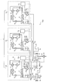
- FIG. 2 is a circuit diagram showing a configuration example of the heat source system shown in FIG.
- FIG. 2 shows a case where each of the pumps 21a to 21c shown in FIG. 1 is provided in each of the heat source devices 10a to 10c. Since the heat source units 10a to 10c have the same configuration, the configuration of the heat source unit 10a will be mainly described in detail here, and the description of the heat source units 10b and 10c will be omitted.
- the heat source device 10a includes a compressor 11, a four-way valve 16, an air heat exchanger 12, a fan 13, an expansion valve 14, a water heat exchanger 15, and a control device 17a.
- the refrigerant circuit 18 includes a compressor 11, a four-way valve 16, an air heat exchanger 12, and an expansion valve 14.
- the water heat exchanger 15 is connected to the refrigerant circuit 18.
- one of the two connection ports is connected to the suction port of the compressor 11 and the other is connected to the discharge port of the compressor 11.
- one connection port is connected to the other connection port via the air heat exchanger 12, the expansion valve 14, and the water heat exchanger 15.
- Compressor 11 compresses and discharges refrigerant to be sucked.
- the air heat exchanger 12 performs heat exchange between air and the refrigerant.
- the four-way valve 16 switches the refrigerant flow path.
- the fan 13 supplies outside air to the air heat exchanger 12.
- the expansion valve 14 adjusts the pressure of the refrigerant to expand the refrigerant.
- the water heat exchanger 15 sends the water supplied from the return water header pipe 23 to the outgoing header pipe 22 after exchanging heat with the refrigerant.
- Water pipes 55 a and 54 a are connected to the water heat exchanger 15.
- the water heat exchanger 15 is connected to the pump 21a through a water pipe 54a.
- the pump 21a is provided with an inverter circuit 24a for controlling the operating frequency.
- the pump 21a operates in a range where the operation frequency is the rated frequency.
- the maximum value is referred to as the maximum frequency
- the minimum value is referred to as the minimum frequency.
- An outlet pressure sensor 41a that measures the water pressure and a temperature sensor 43a that measures the temperature of the water are provided in the water pipe 55a on the water outlet side of the water heat exchanger 15.
- An inlet pressure sensor 42a for measuring the water pressure is provided in the water pipe 54a on the water inlet side of the water heat exchanger 15.
- FIG. 3 is a diagram illustrating a configuration example of each control device provided in the plurality of heat source units illustrated in FIG. 2.
- each of the control devices 17a to 17c includes a memory 71 that stores a program, and a CPU (Central Processing Unit) 72 that executes processing according to the program.
- a CPU Central Processing Unit
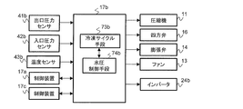
- FIG. 4 is a functional block diagram showing a configuration example of a control device provided in one heat source machine among the plurality of heat source machines shown in FIG.
- FIG. 4 is a functional block diagram illustrating a configuration example of the control device 17a provided in the heat source device 10a.
- the control device 17a is connected to the compressor 11, the four-way valve 16, the expansion valve 14, and the fan 13 through signal lines.
- the control device 17a is connected to the outlet pressure sensor 41a, the inlet pressure sensor 42a, the temperature sensor 43a, the bypass valve 32, the differential pressure gauge 34, and the inverter circuit 24a via signal lines.
- the control device 17a is connected to the control device 17b provided in the heat source device 10b and the control device 17c provided in the heat source device 10c through signal lines.
- the control device 17a includes refrigeration cycle means 73a, water pressure control means 74a, and number control means 75.
- the refrigeration cycle means 73a, the water pressure control means 74a, and the number control means 75 are configured in the control device 17a.
- the memory 71 of the control device 17 a stores information on the target range of the water pressure difference between the return water header pipe 23 and the outgoing water header pipe 22.
- the target range is an allowable range with respect to the water pressure difference on the basis of the determined target value.
- the memory 71 stores information indicating the relationship between the water pressure difference before and after the water heat exchanger 15, the flow rate of the pump 21a, and the operating frequency.
- the control device 17a transmits information on the operation state to the control devices 17b and 17c when an instruction for any one of the cooling operation and the heating operation is input.
- the control device 17a receives information on the operating frequency of the compressor 11 from the control devices 17b and 17c.
- the control device 17a receives the measured values of the temperature sensors 43b and 43c from the control devices 17b and 17c at a constant cycle.
- the control device 17a receives the measured values of the outlet pressure sensors 41b and 41c and the measured values of the inlet pressure sensors 42b and 42c from the control devices 17b and 17c at regular intervals.
- the number control means 75 estimates the amount of heat generated by each refrigerant circuit 18 of the heat source units 10a to 10c from the operating frequency of each compressor 11 of the heat source units 10a to 10c.
- the number control means 75 determines the number of heat source devices to be operated among the heat source devices 10a to 10c from the estimated heat amount and the heat amount necessary for the load.
- the number control means 75 determines the flow rate required for the pump connected to the heat source machine to be operated from the measured values of the temperature sensors 43a to 43c, the outlet pressure sensors 41a to 41c, and the inlet pressure sensors 42a to 42c. calculate. Then, the number control means 75 transmits the operation instruction information including the operation instruction of the heat source apparatus, the operation instruction of the pump, and the information of the target flow rate of the pump to the control device provided in the heat source apparatus to be operated. .
- the refrigeration cycle means 73 a controls the refrigeration cycle in the refrigerant circuit 18.
- the refrigeration cycle means 73a receives an operation instruction from the number control means 75, the refrigeration cycle means 73a switches the flow path of the four-way valve 16 corresponding to the operation state including the cooling operation and the heating operation.
- the refrigeration cycle means 73a controls the operating frequency of the compressor 11 and the fan 13 and the opening degree of the expansion valve 14 so that the water temperature measured by the temperature sensor 43a matches the target temperature.
- the water pressure control means 74a When the water pressure control means 74a receives the operation instruction of the pump 21a from the number control means 75, the water pressure control means 74a obtains the water pressure difference from the measured values of the outlet pressure sensor 41a and the inlet pressure sensor 42a. The water pressure control means 74a calculates the flow rate from the obtained water pressure difference, and controls the operating frequency of the pump 21a via the inverter circuit 24a so that the calculated flow rate becomes the target flow rate.
- the water pressure control means 74a controls the operation frequency of the pump connected to the heat source machine to be operated and the opening degree of the bypass valve 32 so that the water pressure difference acquired from the differential pressure gauge 34 falls within the target range.
- the water pressure control means 74a determines whether or not the operating frequency of the pump being operated is the lowest frequency when performing water pressure control of the bypass pipe 31. As a result of the determination, when the pump operating frequency is not the lowest frequency, the water pressure control means 74a controls the opening degree of the bypass valve 32 to finely adjust the water pressure difference of the bypass pipe 31. As a result of the determination, when the operation frequency of the pump is the lowest frequency, the water pressure control means 74a determines whether or not the opening degree of the bypass valve 32 is the minimum opening degree.
- the water pressure control means 74a controls the operating frequency of the pump to finely adjust the water pressure difference of the bypass pipe 31.
- the water pressure control means 74a controls the opening degree of the bypass valve 32 to thereby reduce the water pressure difference of the bypass pipe 31. Fine tune.
- FIG. 5 is a functional block diagram illustrating a configuration example of a control device provided in a heat source device different from the heat source device provided with the control device illustrated in FIG. 4. Since the control devices 17b and 17c have the same configuration, the configuration of the control device 17b will be described here.
- the control device 17b is connected to the compressor 11, the four-way valve 16, the expansion valve 14, and the fan 13 through signal lines.
- the control device 17a is connected to the outlet pressure sensor 41b, the inlet pressure sensor 42b, the temperature sensor 43b, and the inverter circuit 24b via signal lines.
- the control device 17b is connected to the control devices 17a and 17c through signal lines.
- Control device 17b has refrigeration cycle means 73b and water pressure control means 74b.
- the refrigeration cycle means 73b and the water pressure control means 74b are configured in the control device 17b.
- the memory 71 of the control device 17b stores information indicating the relationship between the water pressure difference before and after the water heat exchanger 15 and the flow rate and operating frequency of the pump 21b.
- the control device 17b transmits the measured value of the temperature sensor 43b to the control device 17a at a constant cycle.
- the control device 17b transmits the measured values of the outlet pressure sensor 41b and the inlet pressure sensor 42b to the control device 17a at a constant cycle.
- the control device 17b transmits information on the operating frequency of the compressor 11 to the control device 17a.
- the refrigeration cycle means 73b controls the refrigeration cycle of the refrigerant circuit 18 in the same manner as the refrigeration cycle means 73a when receiving an operation instruction for the heat source device 10b from the control device 17a.
- the water pressure control means 74b receives an operation instruction of the pump 21b from the control device 17a
- the water pressure control means 74b obtains a water pressure difference from the measured values of the outlet pressure sensor 41b and the inlet pressure sensor 42b.
- the water pressure control means 74b calculates the flow rate from the obtained water pressure difference, and controls the operating frequency of the pump 21b via the inverter circuit 24b so that the calculated flow rate becomes the target flow rate.
- control devices 17a to 17c are provided in the heat source devices 10a to 10c, respectively.
- one control device may be provided.
- the control device 17a may have the functions of the control devices 17b and 17c.
- FIG. 6 is a flowchart showing an operation procedure of the heat source system according to Embodiment 1 of the present invention.
- the control device 17a determines the number of heat source devices to be operated among the heat source devices 10a to 10c based on the amount of heat necessary for the load. Specifically, the control device 17a estimates the amount of heat that can be generated by each refrigerant circuit 18 of the heat source devices 10a to 10c from the operating frequency of each compressor 11. Then, the control device 17a determines the number of heat source devices to be operated among the heat source devices 10a to 10c from the estimated heat amount and the heat amount necessary for the load. Then, the control device 17a operates a pump connected to the operating heat source machine among the pumps 21a to 21c.
- the control device 17a controls the operating frequency of the compressor 11 so that the measured value of the temperature sensor 43a becomes the target temperature. After determining the number of operating heat source units, the control device 17a determines the number of operating heat source units when the estimated amount of heat is less than the amount of heat necessary for the load based on the measured value obtained from the temperature sensor 43a. May increase.
- the control device 17a determines whether or not the operation frequency of the pump 21a is the lowest frequency as follows (step S102).
- the control device 17a calculates the water pressure difference from the measured values of the outlet pressure sensor 41a and the inlet pressure sensor 42a, and calculates the water flow rate of the heat source device 10a alone from the calculated water pressure difference. Subsequently, the control device 17a determines whether or not the calculated water flow rate is the lower limit value of the flow rate range of the heat source device 10a. When the water flow rate is the lower limit value of the flow rate range of the heat source device 10a, the control device 17a determines that the operation frequency of the pump 21a is the lowest frequency.
- control device 17a may determine whether or not the water flow rate is the lower limit value of the flow rate range of the heat source device 10a based on the characteristics of the pump 21a. As a result of the determination, when the water flow rate is the lower limit value of the flow rate range of the heat source device 10a, the control device 17a determines that the frequency of the pump 21a is the lowest frequency. In this case, the memory 71 of the control device 17a stores the flow rate range of the water flowing through the water heat exchangers 15 of the heat source units 10a to 10c and the characteristics of the pumps 21a to 21c.
- step S102 the control device 17a selects either the operating frequency of the pump 21a or the opening degree of the bypass valve 32 as means for finely adjusting the water pressure difference between the outgoing water side and the returning water side. To do.
- step S103 determines whether or not the opening degree of the bypass valve 32 is the minimum opening degree. As a result of the determination in step S103, when the opening degree of the bypass valve 32 is the minimum opening degree, the control device 17a maintains the opening degree of the bypass valve 32 at the minimum opening degree, and the value of the differential pressure gauge 34 enters the target range. In this manner, the frequency of the pump 21a is controlled (step S104).
- the control device 17a finely adjusts the water pressure difference of the bypass pipe 31 using the operating frequency of the pump 21a.
- the opening degree of the bypass valve 32 has a higher sensitivity than the operating frequency of the pump with respect to the water pressure difference between the outgoing water side and the return water side.
- the opening degree of the bypass valve 32 is the minimum opening degree and the operating frequency of the pump 21a is the lowest frequency, the balance between the water pressure on the outgoing water side and the water pressure on the return water side is almost maintained. it is conceivable that. In this state, in order to prevent the balance from being disturbed as much as possible, an operating frequency of the pump 21a having a sensitivity smaller than the opening degree of the bypass valve 32 is selected as a means for adjusting the water pressure difference.
- step S106 the control device 17a maintains the operation frequency of the pump 21a and sets the bypass valve 32 so that the value of the differential pressure gauge 34 falls within the target range. Control is performed (step S106).
- the control device 17a controls the opening degree of the bypass valve 32 that is highly sensitive to the water pressure difference between the outgoing water side and the return water side, thereby making the water pressure difference smoother. Can be adjusted.
- step S106 when the control device 17a adjusts the water pressure difference between the outgoing water side and the return water side with the operating frequency of the pump, the operating frequency of the pump may increase. In this case, the flow rate of water flowing through the load increases.
- step S106 by selecting the opening degree of the bypass valve 32 as a means for adjusting the water pressure difference, an increase in the operating frequency of the pump can be suppressed and an increase in power consumption can be suppressed.
- step S103 when the opening degree of the bypass valve 32 is not the minimum opening degree, the control device 17a maintains the operation frequency of the pump 21a at the lowest frequency so that the value of the differential pressure gauge 34 falls within the target range. Then, the opening degree of the bypass valve 32 is controlled (step S105).
- the operating frequency of the pump is the lowest frequency, the flow rate of water supplied to the load is small, and when the controller 17a adjusts the opening degree of the bypass valve 32, the water pressure difference between the outgoing water side and the return water side is It is thought that it will change greatly. However, even if the control device 17a attempts to control the operation frequency of the pump, the flow rate of water cannot be reduced.
- step S105 the bypass valve 32 having room for fine adjustment in the direction of decreasing the water pressure difference is selected as a means for adjusting the water pressure difference between the outgoing water side and the return water side.
- the number of necessary heat source units is determined from the amount of heat generated by the heat source units 10a to 10c and the necessary amount of heat, and the operating frequency of the pump connected to the operating heat source unit is rated. It is determined whether or not it is the lowest frequency. Then, as a result of the determination, the heat source system 100 controls either the operating frequency of the pump or the opening of the bypass valve 32 so that the water pressure difference between the outgoing water side and the return water side falls within the target range. .
- the pump operating frequency is used as a means for adjusting the water pressure difference between the outgoing water side and the return water side according to the determination result of whether or not the operating frequency of the pump is the lowest frequency.
- One of the opening degrees of the bypass valve 32 is selected. As a result, it is possible to finely adjust the water pressure difference between the outgoing water side and the return water side.
- the heat source system 100 maintains the pump operating frequency when the pump operating frequency is not the lowest frequency, and the water pressure difference between the outgoing water side and the return water side falls within the target range.
- the opening degree of the bypass valve 32 is controlled.
- the heat source system 100 controls the opening degree of the bypass valve 32 that is highly sensitive to the water pressure difference between the outgoing water side and the return water side, thereby smoothing the water pressure difference more smoothly. Can be adjusted. Further, by selecting the opening degree of the bypass valve 32 as the means for adjusting the water pressure difference, it is possible to suppress an increase in the operating frequency of the pump and an increase in power consumption.
- the heat source system 100 When the pump operating frequency is the lowest frequency and the opening degree of the bypass valve 32 is the minimum opening degree, the heat source system 100 is used so that the water pressure difference between the outgoing water side and the return water side is within the target range. Control the operating frequency of the pump to enter. In this case, a state where the balance between the water pressure on the outgoing water side and the water pressure on the return water side is almost maintained is maintained, and the balance can be prevented from being disturbed as much as possible.
- the heat source system 100 maintains the operating frequency of the pump at the lowest frequency,
- the opening degree of the bypass valve 32 is controlled so that the water pressure difference falls within the target range.
- the opening degree of the bypass valve 32 does not reach the minimum opening degree, there is room for fine adjustment of the opening degree of the bypass valve 32. Therefore, as a means for adjusting the water pressure difference between the outgoing water side and the return water side, it is possible to select the bypass valve 32 that has room for fine adjustment to reduce the water pressure difference.
- Embodiment 2 a water switch connected to a load is provided with a flow switch.
- FIG. 7 is a circuit diagram showing a configuration example of the heat source system according to the second embodiment of the present invention. In the second embodiment, detailed description of the same configuration as that of the first embodiment is omitted.
- the flow switch 35 is provided in the water pipe 52 connected to the return water header pipe 23 as compared with the configuration shown in FIG. .
- the flow switch 35 is connected to the control device 17a by a signal line.
- the flow switch 35 outputs a detection signal indicating whether or not water is flowing through the water pipe 52.
- the flow switch 35 When water is flowing through the water pipe 52, the flow switch 35 outputs an off signal detection signal to the control device 17a.
- the flow switch 35 When water does not flow through the water pipe 52, the flow switch 35 outputs an ON signal detection signal to the control device 17a.
- the number control means 75 stops the operation of the compressor 11 of the heat source devices 10a to 10c.
- the number control means 75 operates one of the pumps 21a to 21c and stops the other pumps. At that time, the number control means 75 may set the operation frequency of the pump to be operated to the lowest frequency.
- the water pressure control means 74a controls the opening degree of the bypass valve 32 so that the water pressure difference measured by the differential pressure gauge 34 falls within the target range.
- FIG. 8 is a flowchart showing an operation procedure of the heat source system according to Embodiment 2 of the present invention. Steps S101 to S106 shown in FIG. 8 are the same as the processing described with reference to FIG.
- the control device 17a determines whether the detection signal acquired from the flow switch 35 is in an on state or an off state at a constant cycle (step S201). As a result of the determination, if the detection signal is in the off state, the control device 17a proceeds to step S101. On the other hand, if the result of determination in step S201 is that the detection signal is on, the control device 17a stops the operation of the compressor 11 of the heat source devices 10a to 10c, and turns on one of the pumps 21a to 21c. The other pump is stopped by operating (step S202). Subsequently, the control device 17a sets the operating frequency of one operating pump to the lowest frequency. Further, the control device 17a controls the opening degree of the bypass valve 32 so that the water pressure difference measured by the differential pressure gauge 34 falls within the target range (step S203).
- the heat source units 10a to 10c are stopped, the pump is operated in one unit, and the water pipe The water is circulated between the load and the heat source units 10a to 10c via the.
- the compressors 11 of the heat source units 10a to 10c are stopped, so that power consumption is suppressed.
- Embodiment 3 FIG. In the third embodiment, the position where the differential pressure gauge 34 is provided is different from that in the first embodiment.
- FIG. 9 is a circuit diagram showing a configuration example of the heat source system according to the third embodiment of the present invention. In the third embodiment, detailed description of the same configuration as that of the first embodiment is omitted.
- the distance from the heat source units 10a to 10c among the plurality of fan coil units 60a and 60b is farthest from the configuration shown in FIG.
- a differential pressure gauge 34 is provided in the fan coil unit 60b.
- the distance of the fan coil unit 60b is larger than the distance of the fan coil unit 60a. .
- the differential pressure gauge 34 is connected in parallel to the fan coil unit 60b.
- the differential pressure gauge 34 measures the water pressure difference between the outgoing header pipe 22 side of the heat exchanger 61 and the return water header pipe 23 side of the on-off valve 63.
- the operation of the heat source system 100b according to the third embodiment is the same as the operation described with reference to FIG. 6 in the first embodiment, and thus detailed description thereof is omitted.
- the load that is the farthest from the heat source devices 10a to 10c has a slower flow of supplied water than the other loads. Therefore, at the load farthest from the heat source devices 10a to 10c, the water pressure difference between the outgoing header side and the return water header side becomes the smallest.
- the differential pressure gauge 34 is provided in a load farthest from the heat source devices 10a to 10c among a plurality of loads. Then, the heat source system 100b adjusts the water pressure difference between the outgoing water side and the return water side so that the measured value of the differential pressure gauge 34 falls within the target range.
- the water pressure difference between the outgoing water side and the return water side enters the target range, and a sufficient amount of water is supplied. Furthermore, a sufficient amount of water is supplied to a load that is closer to the load farthest from the heat source devices 10a to 10c.
- Embodiment 4 FIG.
- the fourth embodiment is a combination of the second embodiment and the third embodiment.
- FIG. 10 is a circuit diagram showing a configuration example of a heat source system according to Embodiment 4 of the present invention.
- FIG. 10 detailed description of the same configuration as in the first to third embodiments is omitted.
- the flow switch 35 is provided in the water pipe 52 connected to the return water header pipe 23 as compared with the configuration shown in FIG. Further, in the heat source system 100c of the fourth embodiment, compared to the configuration shown in FIG. 1, among the plurality of fan coil units 60a and 60b, the fan coil unit 60b that is the farthest away from the heat source units 10a to 10c is used. A differential pressure gauge 34 is provided.
- the operation of the heat source system 100c according to the fourth embodiment is the same as the operation described with reference to FIG. 8 in the second embodiment, and thus detailed description thereof is omitted.
- the heat source devices 10a to 10c are stopped and The pump is operated to circulate water. According to the fourth embodiment, not only the same effects as those of the first embodiment but also the respective effects of the second and third embodiments can be obtained.
- Refrigeration cycle device 10a-10c heat source machine, 11 compressor, 12 air heat exchanger, 13 fan, 14 expansion valve, 15 water heat exchanger, 16 four-way valve, 17a-17c control device, 18 refrigerant circuit, 20 return Water header pipe, 21a-21c pump, 22 outgoing header pipe, 23 return water header pipe, 24a-24c inverter circuit, 25 return water header pipe, 31 bypass pipe, 32 bypass valve, 33 tank, 34 differential pressure gauge, 35 flow Switch, 41a-41c outlet pressure sensor, 42a-42c inlet pressure sensor, 43a-43c temperature sensor, 51-53, 54a-54c, 55a-55c water piping, 60, 60a, 60b fan coil unit, 61 heat exchanger, 62 fan, 63 on-off valve, 71 memory, 72 CPU 73a, 73b refrigeration cycle means, 74a, 74b pressure control means, 75 volume control means, 100,100a ⁇ 100c heat source system.
Landscapes
- Engineering & Computer Science (AREA)
- Mechanical Engineering (AREA)
- General Engineering & Computer Science (AREA)
- Chemical & Material Sciences (AREA)
- Combustion & Propulsion (AREA)
- Physics & Mathematics (AREA)
- Thermal Sciences (AREA)
- Life Sciences & Earth Sciences (AREA)
- Sustainable Development (AREA)
- Air Conditioning Control Device (AREA)
- Other Air-Conditioning Systems (AREA)
Abstract
La présente invention concerne un système de source de chaleur comprenant : une pluralité de dispositifs source de chaleur comportant chacun un circuit de fluide frigorigène comprenant un échangeur de chaleur à eau ; un tuyau collecteur d'alimentation en eau à travers lequel de l'eau coulant à partir de la pluralité d'échangeurs de chaleur à eau est combinée et alimentée à une charge ; un tuyau collecteur de retour d'eau à travers lequel l'eau coulant à partir de la charge est divisée vers la pluralité d'échangeurs de chaleur à eau ; une pluralité de pompes destinées à alimenter en eau la pluralité d'échangeurs de chaleur à eau ; une tuyauterie de dérivation destinée à relier le tuyau collecteur d'alimentation en eau et le tuyau collecteur de retour d'eau ; une soupape de dérivation agencée au niveau de la tuyauterie de dérivation ; un manomètre différentiel destiné à mesurer la différence de pression d'eau entre la pression de l'eau alimentée à la charge et la pression de l'eau retournant de la charge ; et un dispositif de commande destiné à commander la pluralité de dispositifs source de chaleur et la pluralité de pompes. Le dispositif de commande détermine, en fonction d'une quantité de chaleur requise et d'une quantité de chaleur produite par une pluralité de circuits de fluide frigorigène, le nombre de dispositifs source de chaleur devant être actionnés parmi la pluralité de dispositifs source de chaleur, détermine si la fréquence de fonctionnement d'une pompe reliée au dispositif source de chaleur en fonctionnement est la fréquence minimale, et commande soit la fréquence de fonctionnement de la pompe, soit le degré d'ouverture de la soupape de dérivation, en fonction du résultat de la détermination, de sorte que la différence de pression d'eau soit comprise dans une plage cible.
Priority Applications (4)
| Application Number | Priority Date | Filing Date | Title |
|---|---|---|---|
| JP2019523297A JP6723450B2 (ja) | 2017-06-08 | 2017-06-08 | 熱源システム |
| PCT/JP2017/021342 WO2018225221A1 (fr) | 2017-06-08 | 2017-06-08 | Système de source de chaleur |
| US16/494,488 US11187439B2 (en) | 2017-06-08 | 2017-06-08 | Heat source system |
| EP17913091.9A EP3637006B1 (fr) | 2017-06-08 | 2017-06-08 | Système de source de chaleur |
Applications Claiming Priority (1)
| Application Number | Priority Date | Filing Date | Title |
|---|---|---|---|
| PCT/JP2017/021342 WO2018225221A1 (fr) | 2017-06-08 | 2017-06-08 | Système de source de chaleur |
Publications (1)
| Publication Number | Publication Date |
|---|---|
| WO2018225221A1 true WO2018225221A1 (fr) | 2018-12-13 |
Family
ID=64565799
Family Applications (1)
| Application Number | Title | Priority Date | Filing Date |
|---|---|---|---|
| PCT/JP2017/021342 Ceased WO2018225221A1 (fr) | 2017-06-08 | 2017-06-08 | Système de source de chaleur |
Country Status (4)
| Country | Link |
|---|---|
| US (1) | US11187439B2 (fr) |
| EP (1) | EP3637006B1 (fr) |
| JP (1) | JP6723450B2 (fr) |
| WO (1) | WO2018225221A1 (fr) |
Cited By (5)
| Publication number | Priority date | Publication date | Assignee | Title |
|---|---|---|---|---|
| CN111795480A (zh) * | 2019-04-08 | 2020-10-20 | 开利公司 | 热循环系统和用于热循环系统的控制方法 |
| CN113405151A (zh) * | 2021-06-04 | 2021-09-17 | 青岛海信日立空调系统有限公司 | 一种用于地暖空调的线控器 |
| CN114198832A (zh) * | 2021-12-21 | 2022-03-18 | 宁波奥克斯电气股份有限公司 | 一种空调系统、恒流节能控制方法及变流节能控制方法 |
| WO2023084698A1 (fr) | 2021-11-11 | 2023-05-19 | 三菱電機株式会社 | Système de climatisation |
| JPWO2023195125A1 (fr) * | 2022-04-07 | 2023-10-12 |
Families Citing this family (7)
| Publication number | Priority date | Publication date | Assignee | Title |
|---|---|---|---|---|
| EP3954352B1 (fr) | 2013-03-15 | 2024-08-21 | Hayward Industries, Inc. | Système de commande modulaire pour piscine/spa |
| US11720085B2 (en) * | 2016-01-22 | 2023-08-08 | Hayward Industries, Inc. | Systems and methods for providing network connectivity and remote monitoring, optimization, and control of pool/spa equipment |
| CN110160230B (zh) * | 2019-05-27 | 2021-12-28 | 上海美控智慧建筑有限公司 | 中央空调、空调水系统及其控制方法和控制装置 |
| CN111256202B (zh) * | 2020-01-19 | 2021-10-26 | 深圳市奥宇节能技术股份有限公司 | 一种集中供热系统热源热侧变频循环泵群控方法 |
| CN111854119B (zh) * | 2020-07-21 | 2021-09-14 | 珠海格力电器股份有限公司 | 冷水机组负荷输出无极调节控制方法及冷水机组 |
| CN113749480B (zh) * | 2021-08-12 | 2022-09-09 | 珠海格力电器股份有限公司 | 制冷设备的控制方法、装置、控制器和制冷设备 |
| CN114636186B (zh) * | 2022-04-17 | 2023-05-26 | 台州半城暖通科技有限公司 | 一种分集水器旁通控制方法 |
Citations (8)
| Publication number | Priority date | Publication date | Assignee | Title |
|---|---|---|---|---|
| JP2001241735A (ja) * | 2000-02-24 | 2001-09-07 | Matsushita Electric Works Ltd | 空気調和システムおよびその制御方法 |
| JP2002098358A (ja) * | 2000-09-26 | 2002-04-05 | Dai-Dan Co Ltd | 一次ポンプ方式熱源変流量システム |
| JP2004278884A (ja) * | 2003-03-14 | 2004-10-07 | Mitsubishi Jisho Sekkei Inc | 制御装置 |
| JP2005127586A (ja) * | 2003-10-23 | 2005-05-19 | Yamatake Corp | 1次ポンプ方式熱源変流量制御システムおよび1次ポンプ最低流量確保方法 |
| JP2005299980A (ja) * | 2004-04-08 | 2005-10-27 | Yamatake Corp | 送水制御装置およびその方法 |
| JP2006170547A (ja) * | 2004-12-17 | 2006-06-29 | Nippon Engineering Kk | 空調システムの制御方法及び制御装置及び空調システム |
| JP2010190438A (ja) * | 2009-02-16 | 2010-09-02 | Shin Nippon Air Technol Co Ltd | 1ポンプ方式熱源設備の運転制御方法 |
| JP2011153809A (ja) | 2010-01-28 | 2011-08-11 | Arefu Net:Kk | 熱源制御システムおよび熱源制御方法 |
Family Cites Families (4)
| Publication number | Priority date | Publication date | Assignee | Title |
|---|---|---|---|---|
| JP4123513B2 (ja) * | 2003-10-22 | 2008-07-23 | 株式会社デンソー | 燃料噴射弁 |
| JP5836156B2 (ja) * | 2012-02-28 | 2015-12-24 | 三菱重工業株式会社 | 熱源システム及びその熱媒流量制御方法 |
| JP6119141B2 (ja) * | 2012-08-07 | 2017-04-26 | ダイキン工業株式会社 | 空調システム |
| JP6422590B2 (ja) * | 2015-10-19 | 2018-11-14 | 三菱電機株式会社 | 熱源システム |
-
2017
- 2017-06-08 WO PCT/JP2017/021342 patent/WO2018225221A1/fr not_active Ceased
- 2017-06-08 EP EP17913091.9A patent/EP3637006B1/fr active Active
- 2017-06-08 JP JP2019523297A patent/JP6723450B2/ja active Active
- 2017-06-08 US US16/494,488 patent/US11187439B2/en not_active Expired - Fee Related
Patent Citations (8)
| Publication number | Priority date | Publication date | Assignee | Title |
|---|---|---|---|---|
| JP2001241735A (ja) * | 2000-02-24 | 2001-09-07 | Matsushita Electric Works Ltd | 空気調和システムおよびその制御方法 |
| JP2002098358A (ja) * | 2000-09-26 | 2002-04-05 | Dai-Dan Co Ltd | 一次ポンプ方式熱源変流量システム |
| JP2004278884A (ja) * | 2003-03-14 | 2004-10-07 | Mitsubishi Jisho Sekkei Inc | 制御装置 |
| JP2005127586A (ja) * | 2003-10-23 | 2005-05-19 | Yamatake Corp | 1次ポンプ方式熱源変流量制御システムおよび1次ポンプ最低流量確保方法 |
| JP2005299980A (ja) * | 2004-04-08 | 2005-10-27 | Yamatake Corp | 送水制御装置およびその方法 |
| JP2006170547A (ja) * | 2004-12-17 | 2006-06-29 | Nippon Engineering Kk | 空調システムの制御方法及び制御装置及び空調システム |
| JP2010190438A (ja) * | 2009-02-16 | 2010-09-02 | Shin Nippon Air Technol Co Ltd | 1ポンプ方式熱源設備の運転制御方法 |
| JP2011153809A (ja) | 2010-01-28 | 2011-08-11 | Arefu Net:Kk | 熱源制御システムおよび熱源制御方法 |
Non-Patent Citations (1)
| Title |
|---|
| See also references of EP3637006A4 |
Cited By (8)
| Publication number | Priority date | Publication date | Assignee | Title |
|---|---|---|---|---|
| CN111795480A (zh) * | 2019-04-08 | 2020-10-20 | 开利公司 | 热循环系统和用于热循环系统的控制方法 |
| CN111795480B (zh) * | 2019-04-08 | 2023-08-22 | 开利公司 | 热循环系统和用于热循环系统的控制方法 |
| CN113405151A (zh) * | 2021-06-04 | 2021-09-17 | 青岛海信日立空调系统有限公司 | 一种用于地暖空调的线控器 |
| WO2023084698A1 (fr) | 2021-11-11 | 2023-05-19 | 三菱電機株式会社 | Système de climatisation |
| CN114198832A (zh) * | 2021-12-21 | 2022-03-18 | 宁波奥克斯电气股份有限公司 | 一种空调系统、恒流节能控制方法及变流节能控制方法 |
| JPWO2023195125A1 (fr) * | 2022-04-07 | 2023-10-12 | ||
| WO2023195125A1 (fr) * | 2022-04-07 | 2023-10-12 | 三菱電機株式会社 | Système à cycle frigorifique |
| JP7630716B2 (ja) | 2022-04-07 | 2025-02-17 | 三菱電機株式会社 | 冷凍サイクルシステム |
Also Published As
| Publication number | Publication date |
|---|---|
| EP3637006A4 (fr) | 2020-06-03 |
| EP3637006B1 (fr) | 2024-01-03 |
| US11187439B2 (en) | 2021-11-30 |
| EP3637006A1 (fr) | 2020-04-15 |
| JPWO2018225221A1 (ja) | 2019-12-26 |
| US20200096238A1 (en) | 2020-03-26 |
| JP6723450B2 (ja) | 2020-07-15 |
Similar Documents
| Publication | Publication Date | Title |
|---|---|---|
| WO2018225221A1 (fr) | Système de source de chaleur | |
| US9644876B2 (en) | Refrigeration cycle apparatus | |
| CN102207324B (zh) | 空调机 | |
| CN104006441B (zh) | 流体回路系统 | |
| US20180017271A1 (en) | Multi-online system | |
| CN103154626B (zh) | 热源装置 | |
| CN107709887B (zh) | 空气调节装置以及运行控制装置 | |
| JP6785886B2 (ja) | 冷凍サイクル装置 | |
| JP6123289B2 (ja) | 空気調和システム | |
| US10077930B2 (en) | Air-conditioning apparatus and air-conditioning system | |
| JP6422590B2 (ja) | 熱源システム | |
| GB2555064A (en) | Refrigeration system | |
| JP2013160478A (ja) | 空気調和装置 | |
| WO2020110289A1 (fr) | Dispositif de régulation et dispositif de climatisation | |
| JP3550336B2 (ja) | 冷暖房システム | |
| JP6603627B2 (ja) | 空調システム及び運転制御方法 | |
| JP2015068633A (ja) | 冷媒分流ユニット及びこれを用いた空気調和機 | |
| JP7398864B2 (ja) | 空調システム | |
| JP2009109059A (ja) | 空気調和装置 | |
| JP2018132218A (ja) | 空気調和装置 | |
| JP2013204890A (ja) | 空調制御システムおよび空調制御方法 | |
| WO2022123689A1 (fr) | Dispositif de relais et dispositif de climatisation |
Legal Events
| Date | Code | Title | Description |
|---|---|---|---|
| ENP | Entry into the national phase |
Ref document number: 2019523297 Country of ref document: JP Kind code of ref document: A |
|
| NENP | Non-entry into the national phase |
Ref country code: DE |
|
| 121 | Ep: the epo has been informed by wipo that ep was designated in this application |
Ref document number: 17913091 Country of ref document: EP Kind code of ref document: A1 |
|
| ENP | Entry into the national phase |
Ref document number: 2017913091 Country of ref document: EP Effective date: 20200108 |