WO2018226072A2 - 무선 통신 시스템에서 오버로드 제어 방법 및 이를 위한 장치 - Google Patents
무선 통신 시스템에서 오버로드 제어 방법 및 이를 위한 장치 Download PDFInfo
- Publication number
- WO2018226072A2 WO2018226072A2 PCT/KR2018/006551 KR2018006551W WO2018226072A2 WO 2018226072 A2 WO2018226072 A2 WO 2018226072A2 KR 2018006551 W KR2018006551 W KR 2018006551W WO 2018226072 A2 WO2018226072 A2 WO 2018226072A2
- Authority
- WO
- WIPO (PCT)
- Prior art keywords
- message
- data
- control plane
- rrc
- layer
- Prior art date
- Legal status (The legal status is an assumption and is not a legal conclusion. Google has not performed a legal analysis and makes no representation as to the accuracy of the status listed.)
- Ceased
Links
Images


Classifications
-
- H—ELECTRICITY
- H04—ELECTRIC COMMUNICATION TECHNIQUE
- H04W—WIRELESS COMMUNICATION NETWORKS
- H04W76/00—Connection management
- H04W76/30—Connection release
- H04W76/32—Release of transport tunnels
-
- H—ELECTRICITY
- H04—ELECTRIC COMMUNICATION TECHNIQUE
- H04W—WIRELESS COMMUNICATION NETWORKS
- H04W28/00—Network traffic management; Network resource management
- H04W28/02—Traffic management, e.g. flow control or congestion control
- H04W28/0231—Traffic management, e.g. flow control or congestion control based on communication conditions
- H04W28/0242—Determining whether packet losses are due to overload or to deterioration of radio communication conditions
-
- H—ELECTRICITY
- H04—ELECTRIC COMMUNICATION TECHNIQUE
- H04W—WIRELESS COMMUNICATION NETWORKS
- H04W28/00—Network traffic management; Network resource management
- H04W28/02—Traffic management, e.g. flow control or congestion control
- H04W28/0284—Traffic management, e.g. flow control or congestion control detecting congestion or overload during communication
-
- H—ELECTRICITY
- H04—ELECTRIC COMMUNICATION TECHNIQUE
- H04W—WIRELESS COMMUNICATION NETWORKS
- H04W76/00—Connection management
- H04W76/10—Connection setup
- H04W76/19—Connection re-establishment
-
- H—ELECTRICITY
- H04—ELECTRIC COMMUNICATION TECHNIQUE
- H04W—WIRELESS COMMUNICATION NETWORKS
- H04W76/00—Connection management
- H04W76/20—Manipulation of established connections
- H04W76/22—Manipulation of transport tunnels
-
- H—ELECTRICITY
- H04—ELECTRIC COMMUNICATION TECHNIQUE
- H04W—WIRELESS COMMUNICATION NETWORKS
- H04W76/00—Connection management
- H04W76/20—Manipulation of established connections
- H04W76/27—Transitions between radio resource control [RRC] states
-
- H—ELECTRICITY
- H04—ELECTRIC COMMUNICATION TECHNIQUE
- H04W—WIRELESS COMMUNICATION NETWORKS
- H04W76/00—Connection management
- H04W76/30—Connection release
-
- H—ELECTRICITY
- H04—ELECTRIC COMMUNICATION TECHNIQUE
- H04W—WIRELESS COMMUNICATION NETWORKS
- H04W28/00—Network traffic management; Network resource management
- H04W28/02—Traffic management, e.g. flow control or congestion control
- H04W28/0289—Congestion control
Definitions
- the present invention relates to a wireless communication system, and more particularly, to a method of performing / supporting an overload control method and an apparatus supporting the same.
- Mobile communication systems have been developed to provide voice services while ensuring user activity.
- the mobile communication system has expanded not only voice but also data service.As a result of the explosive increase in traffic, a shortage of resources and users are demanding higher speed services, a more advanced mobile communication system is required. have.
- An object of the present invention is to propose a method for performing a method for controlling a control plane overload of a core network.
- a method for a base station performing overload control in a wireless communication system comprising: receiving an overload start message from a core network; Receiving a first Radio Resource Control (RRC) message including a Non-Access Stratum (NAS) message from a user equipment (UE) and indicating transmission of data through a control plane in the first RRC message If the instructions are included, the method may include transmitting an RRC connection release message to the UE to instruct release of the RRC connection.
- RRC Radio Resource Control
- NAS Non-Access Stratum
- the method further includes receiving a second RRC message including an RRC establishment cause from the UE, wherein the RRC establishment cause is a Mobile Originated (MO) data or a Mobile Originated MO. ) May be a signaling (mo-signalling) or a delay tolerant access (delayTolerantAccess).
- the RRC establishment cause is a Mobile Originated (MO) data or a Mobile Originated MO.
- MO Mobile Originated
- MO Mobile Originated
- DelayTolerantAccess delay tolerant access
- the RRC connection release message may include a wait time for a user data connection through a control plane (CP).
- CP control plane
- an indication requesting the use of only CP Cellular Internet of Things (CIoT) Evolved Packet System (EPS) optimization may be used as the indication.
- CIoT Cellular Internet of Things
- EPS Evolved Packet System
- the UE is a UE using narrowband-NoT (NB) Radio Access Technology (RAT)
- NB narrowband-NoT
- RAT Radio Access Technology
- the indication when the indication is data transmission through control plane CIoT EPS optimization, the indication may be regarded as data transmission through control plane CIoT EPS optimization with a request for use of control plane CIoT EPS optimization.
- the NAS message includes a Control Plane Service Request (CPSR) message including MO data or a Tracking Area Update (TAU) request including a signaling active flag (TAU Request). Message).
- CPSR Control Plane Service Request
- TAU Tracking Area Update
- TAU Request signaling active flag
- a NAS (Non-Access Stratum) layer of the data through the control plane Delivering an indication for instructing transmission and a NAS message to an access stratum (AS) layer, wherein the AS layer transmits a first Radio Resource Control (RRC) message including the indication and the NAS message to a base station;
- RRC Radio Resource Control
- the AS layer receives an RRC connection release message including a waiting time for accessing a user data through a control plane (CP) from the base station, converts the waiting time to the NAS layer. And applying the wait time to a back-off timer by the NAS layer.
- RRC Radio Resource Control
- the AS layer further includes transmitting a second RRC message including an RRC establishment cause to the base station, wherein the RRC establishment cause is a mobile originated (MO) data or a call origination (MO).
- RRC establishment cause is a mobile originated (MO) data or a call origination (MO).
- MO Mobile Originated
- MO may be mo-signalling or delayTolerantAccess.
- an indication requesting the use of only CP Cellular Internet of Things (CIoT) Evolved Packet System (EPS) optimization may be used as the indication.
- CIoT Cellular Internet of Things
- EPS Evolved Packet System
- the UE is a UE using narrowband-NoT (NB) Radio Access Technology (RAT)
- NB narrowband-NoT
- RAT Radio Access Technology
- the NAS message includes a Control Plane Service Request (CPSR) message including MO data or a Tracking Area Update (TAU) request including a signaling active flag (TAU Request). Message).
- CPSR Control Plane Service Request
- TAU Tracking Area Update
- TAU Request signaling active flag
- FIG. 1 is a view briefly illustrating an EPS (Evolved Packet System) to which the present invention can be applied.
- EPS Evolved Packet System
- E-UTRAN evolved universal terrestrial radio access network
- FIG. 3 illustrates the structure of an E-UTRAN and an EPC in a wireless communication system to which the present invention can be applied.
- FIG. 4 shows a structure of a radio interface protocol between a terminal and an E-UTRAN in a wireless communication system to which the present invention can be applied.
- FIG. 5 is a diagram exemplarily illustrating a structure of a physical channel in a wireless communication system to which the present invention can be applied.
- FIG. 6 is a diagram for explaining a contention based random access procedure in a wireless communication system to which the present invention can be applied.
- FIG. 7 illustrates an overload start procedure in a wireless communication system to which the present invention can be applied.
- FIG. 8 illustrates an overload stop procedure in a wireless communication system to which the present invention can be applied.
- FIG. 9 illustrates a procedure for an overload start message for data transmission through a control plane in a wireless communication system to which the present invention can be applied.
- FIG. 10 is a diagram illustrating an overload control method according to an embodiment of the present invention.
- FIG. 11 is a diagram illustrating an overload control method according to an embodiment of the present invention.
- FIG. 12 illustrates a block diagram of a communication device according to an embodiment of the present invention.
- FIG. 13 illustrates a block diagram of a communication device according to an embodiment of the present invention.
- a base station has a meaning as a terminal node of a network that directly communicates with a terminal.
- the specific operation described as performed by the base station in this document may be performed by an upper node of the base station in some cases. That is, it is obvious that various operations performed for communication with a terminal in a network composed of a plurality of network nodes including a base station may be performed by the base station or other network nodes other than the base station.
- a 'base station (BS)' may be replaced by terms such as a fixed station, a Node B, an evolved-NodeB (eNB), a base transceiver system (BTS), an access point (AP), and the like. .
- a 'terminal' may be fixed or mobile, and may include a user equipment (UE), a mobile station (MS), a user terminal (UT), a mobile subscriber station (MSS), a subscriber station (SS), and an AMS ( Advanced Mobile Station (WT), Wireless Terminal (WT), Machine-Type Communication (MTC) Device, Machine-to-Machine (M2M) Device, Device-to-Device (D2D) Device, etc.
- UE user equipment
- MS mobile station
- UT user terminal
- MSS mobile subscriber station
- SS subscriber station
- AMS Advanced Mobile Station
- WT Wireless Terminal
- MTC Machine-Type Communication
- M2M Machine-to-Machine
- D2D Device-to-Device
- downlink means communication from a base station to a terminal
- uplink means communication from a terminal to a base station.
- a transmitter may be part of a base station, and a receiver may be part of a terminal.
- a transmitter may be part of a terminal and a receiver may be part of a base station.
- CDMA code division multiple access
- FDMA frequency division multiple access
- TDMA time division multiple access
- OFDMA orthogonal frequency division multiple access
- SC-FDMA single carrier frequency division multiple access
- GSM global system for mobile communications
- GPRS general packet radio service
- EDGE enhanced data rates for GSM evolution
- OFDMA may be implemented in a wireless technology such as IEEE 802.11 (Wi-Fi), IEEE 802.16 (WiMAX), IEEE 802-20, evolved UTRA (E-UTRA).
- UTRA is part of a universal mobile telecommunications system (UMTS).
- 3rd generation partnership project (3GPP) long term evolution (LTE) is a part of evolved UMTS (E-UMTS) using E-UTRA, and employs OFDMA in downlink and SC-FDMA in uplink.
- LTE-A (advanced) is the evolution of 3GPP LTE.
- Embodiments of the present invention may be supported by standard documents disclosed in at least one of the wireless access systems IEEE 802, 3GPP and 3GPP2. That is, steps or parts which are not described to clearly reveal the technical spirit of the present invention among the embodiments of the present invention may be supported by the above documents. In addition, all terms disclosed in the present document can be described by the above standard document.
- UMTS Universal Mobile Telecommunications System
- GSM Global System for Mobile Communication
- Evolved Packet System A network system consisting of an Evolved Packet Core (EPC), which is a packet switched core network based on Internet Protocol (IP), and an access network such as LTE and UTRAN.
- EPC Evolved Packet Core
- IP Internet Protocol
- UMTS is an evolutionary network.
- NodeB base station of UMTS network. It is installed outdoors and its coverage is macro cell size.
- eNodeB base station of EPS network. It is installed outdoors and its coverage is macro cell size.
- a terminal may be referred to in terms of terminal, mobile equipment (ME), mobile station (MS), and the like.
- the terminal may be a portable device such as a laptop, a mobile phone, a personal digital assistant (PDA), a smartphone, a multimedia device, or the like, or may be a non-portable device such as a personal computer (PC) or a vehicle-mounted device.
- the term "terminal” or “terminal” in the MTC related content may refer to an MTC terminal.
- IMS IP Multimedia Subsystem
- IMSI International Mobile Subscriber Identity
- RAN Radio Access Network: a unit including a Node B, a Radio Network Controller (RNC), and an eNodeB controlling the Node B in a 3GPP network. It exists at the terminal end and provides connection to the core network.
- RNC Radio Network Controller
- HLR Home Location Register
- HSS Home Subscriber Server
- PLMN Public Land Mobile Network
- FIG. 1 is a diagram briefly illustrating an EPS (Evolved Packet System) to which the present invention may be applied.
- EPS Evolved Packet System
- the network structure diagram of FIG. 1 briefly reconstructs a structure of an EPS (Evolved Packet System) including an Evolved Packet Core (EPC).
- EPS Evolved Packet System
- EPC Evolved Packet Core
- EPC Evolved Packet Core
- SAE System Architecture Evolution
- SAE is a research project to determine network structure supporting mobility between various kinds of networks.
- SAE aims to provide an optimized packet-based system, for example, supporting various radio access technologies on an IP basis and providing improved data transfer capability.
- the EPC is a core network of an IP mobile communication system for a 3GPP LTE system and may support packet-based real-time and non-real-time services.
- a conventional mobile communication system i.e., a second generation or third generation mobile communication system
- the core network is divided into two distinct sub-domains of circuit-switched (CS) for voice and packet-switched (PS) for data.
- CS circuit-switched
- PS packet-switched
- the function has been implemented.
- the sub-domains of CS and PS have been unified into one IP domain.
- the EPC may include various components, and in FIG. 1, some of them correspond to a Serving Gateway (SGW) (or S-GW), PDN GW (Packet Data Network Gateway) (or PGW or P-GW), A mobility management entity (MME), a Serving General Packet Radio Service (GPRS) Supporting Node (SGSN), and an enhanced Packet Data Gateway (ePDG) are shown.
- SGW Serving Gateway
- PDN GW Packet Data Network Gateway
- MME mobility management entity
- GPRS General Packet Radio Service
- SGSN Serving General Packet Radio Service
- ePDG enhanced Packet Data Gateway
- the SGW acts as a boundary point between the radio access network (RAN) and the core network, and is an element that functions to maintain a data path between the eNodeB and the PDN GW.
- the SGW serves as a local mobility anchor point. That is, packets may be routed through the SGW for mobility in the E-UTRAN (Universal Mobile Telecommunications System (Evolved-UMTS) Terrestrial Radio Access Network defined in 3GPP Release-8 or later).
- E-UTRAN Universal Mobile Telecommunications System (Evolved-UMTS) Terrestrial Radio Access Network defined in 3GPP Release-8 or later.
- SGW also provides mobility with other 3GPP networks (RANs defined before 3GPP Release-8, such as UTRAN or GERAN (Global System for Mobile Communication (GSM) / Enhanced Data rates for Global Evolution (EDGE) Radio Access Network). It can also function as an anchor point.
- GSM Global System for Mobile Communication
- EDGE Enhanced Data rates for Global Evolution
- the PDN GW corresponds to the termination point of the data interface towards the packet data network.
- the PDN GW may support policy enforcement features, packet filtering, charging support, and the like.
- untrusted networks such as 3GPP networks and non-3GPP networks (e.g., Interworking Wireless Local Area Networks (I-WLANs), trusted divisions such as Code Division Multiple Access (CDMA) networks or Wimax). It can serve as an anchor point for mobility management with the network.
- I-WLANs Interworking Wireless Local Area Networks
- CDMA Code Division Multiple Access
- FIG. 1 shows that the SGW and the PDN GW are configured as separate gateways, two gateways may be implemented according to a single gateway configuration option.
- the MME is an element that performs signaling and control functions for supporting access to a network connection, allocation of network resources, tracking, paging, roaming, handover, and the like.
- the MME controls the control plane functions related to subscriber and session management.
- the MME manages a number of eNodeBs and performs signaling for the selection of a conventional gateway for handover to other 2G / 3G networks.
- the MME also performs functions such as security procedures, terminal-to-network session handling, and idle terminal location management.
- SGSN handles all packet data, such as user's mobility management and authentication to other 3GPP networks (eg GPRS networks).
- 3GPP networks eg GPRS networks.
- the ePDG acts as a secure node for untrusted non-3GPP networks (eg, I-WLAN, WiFi hotspots, etc.).
- untrusted non-3GPP networks eg, I-WLAN, WiFi hotspots, etc.
- a terminal having IP capability includes an IP service network provided by an operator (ie, an operator) via various elements in the EPC, based on 3GPP access as well as non-3GPP access.
- an operator ie, an operator
- 3GPP access based on 3GPP access as well as non-3GPP access.
- IMS IMS
- FIG. 1 illustrates various reference points (eg, S1-U, S1-MME, etc.).
- a conceptual link defining two functions existing in different functional entities of E-UTRAN and EPC is defined as a reference point.
- Table 1 below summarizes the reference points shown in FIG. 1.
- various reference points may exist according to the network structure.
- S2a and S2b correspond to non-3GPP interfaces.
- S2a is a reference point that provides the user plane with relevant control and mobility resources between trusted non-3GPP access and PDN GW.
- S2b is a reference point that provides the user plane with relevant control and mobility support between the ePDG and the PDN GW.
- E-UTRAN evolved universal terrestrial radio access network
- the E-UTRAN system is an evolution from the existing UTRAN system and may be, for example, a 3GPP LTE / LTE-A system.
- Communication networks are widely deployed to provide various communication services, such as voice (eg, Voice over Internet Protocol (VoIP)) over IMS and packet data.
- voice eg, Voice over Internet Protocol (VoIP)
- VoIP Voice over Internet Protocol
- an E-UMTS network includes an E-UTRAN, an EPC, and one or more UEs.
- the E-UTRAN consists of eNBs providing a control plane and a user plane protocol to the UE, and the eNBs are connected through an X2 interface.
- X2 user plane interface (X2-U) is defined between eNBs.
- the X2-U interface provides non guaranteed delivery of user plane packet data units (PDUs).
- An X2 control plane interface (X2-CP) is defined between two neighboring eNBs.
- X2-CP performs functions such as context transfer between eNBs, control of user plane tunnel between source eNB and target eNB, delivery of handover related messages, and uplink load management.
- the eNB is connected to the terminal through a wireless interface and is connected to an evolved packet core (EPC) through the S1 interface.
- EPC evolved packet core
- the S1 user plane interface (S1-U) is defined between the eNB and the serving gateway (S-GW).
- the S1 control plane interface (S1-MME) is defined between the eNB and the mobility management entity (MME).
- the S1 interface performs an evolved packet system (EPS) bearer service management function, a non-access stratum (NAS) signaling transport function, network sharing, and MME load balancing function.
- EPS evolved packet system
- NAS non-access stratum
- the S1 interface supports a many-to-many-relation between eNB and MME / S-GW.
- MME provides NAS signaling security, access stratum (AS) security control, inter-CN inter-CN signaling to support mobility between 3GPP access networks, and performing and controlling paging retransmission.
- EWS Earthquake and Tsunami Warning System
- CMAS Commercial Mobile Alert System
- FIG. 3 illustrates the structure of an E-UTRAN and an EPC in a wireless communication system to which the present invention can be applied.
- an eNB may select a gateway (eg, MME), route to the gateway during radio resource control (RRC) activation, scheduling of a broadcast channel (BCH), and the like. Dynamic resource allocation to the UE in transmission, uplink and downlink, and may perform the function of mobility control connection in the LTE_ACTIVE state.
- the gateway is responsible for paging initiation, LTE_IDLE state management, ciphering of the user plane, System Architecture Evolution (SAE) bearer control, and NAS signaling encryption. It can perform the functions of ciphering and integrity protection.
- FIG. 4 shows a structure of a radio interface protocol between a terminal and an E-UTRAN in a wireless communication system to which the present invention can be applied.
- FIG. 4 (a) shows the radio protocol structure for the control plane and FIG. 4 (b) shows the radio protocol structure for the user plane.
- the layers of the air interface protocol between the terminal and the E-UTRAN are based on the lower three layers of the open system interconnection (OSI) standard model known in the art of communication systems. It may be divided into a first layer L1, a second layer L2, and a third layer L3.
- the air interface protocol between the UE and the E-UTRAN consists of a physical layer, a data link layer, and a network layer horizontally, and vertically stacks a protocol stack for transmitting data information. (protocol stack) It is divided into a user plane and a control plane, which is a protocol stack for transmitting control signals.
- the control plane refers to a path through which control messages used by the terminal and the network to manage a call are transmitted.
- the user plane refers to a path through which data generated at an application layer, for example, voice data or Internet packet data, is transmitted.
- an application layer for example, voice data or Internet packet data
- a physical layer which is a first layer (L1), provides an information transfer service to a higher layer by using a physical channel.
- the physical layer is connected to a medium access control (MAC) layer located at a higher level through a transport channel, and data is transmitted between the MAC layer and the physical layer through the transport channel.
- Transport channels are classified according to how and with what characteristics data is transmitted over the air interface.
- data is transmitted between different physical layers through a physical channel between a physical layer of a transmitter and a physical layer of a receiver.
- the physical layer is modulated by an orthogonal frequency division multiplexing (OFDM) scheme and utilizes time and frequency as radio resources.
- OFDM orthogonal frequency division multiplexing
- a physical downlink control channel is a resource allocation of a paging channel (PCH) and a downlink shared channel (DL-SCH) and uplink shared channel (UL-SCH) to the UE. : informs hybrid automatic repeat request (HARQ) information associated with an uplink shared channel (HARQ).
- the PDCCH may carry an UL grant that informs the UE of resource allocation of uplink transmission.
- the physical control format indicator channel (PCFICH) informs the UE of the number of OFDM symbols used for PDCCHs and is transmitted every subframe.
- a physical HARQ indicator channel (PHICH) carries a HARQ acknowledgment (ACK) / non-acknowledge (NACK) signal in response to uplink transmission.
- the physical uplink control channel (PUCCH) carries uplink control information such as HARQ ACK / NACK, downlink request and channel quality indicator (CQI) for downlink transmission.
- a physical uplink shared channel (PUSCH) carries a UL-SCH.
- the MAC layer of the second layer provides a service to a radio link control (RLC) layer, which is a higher layer, through a logical channel.
- RLC radio link control
- the MAC layer multiplexes / demultiplexes into a transport block provided as a physical channel on a transport channel of a MAC service data unit (SDU) belonging to the logical channel and mapping between the logical channel and the transport channel.
- SDU MAC service data unit
- the RLC layer of the second layer supports reliable data transmission. Functions of the RLC layer include concatenation, segmentation, and reassembly of RLC SDUs.
- the RLC layer In order to guarantee the various quality of service (QoS) required by the radio bearer (RB), the RLC layer has a transparent mode (TM), an unacknowledged mode (UM) and an acknowledgment mode (AM). There are three modes of operation: acknowledge mode.
- AM RLC provides error correction through an automatic repeat request (ARQ). Meanwhile, when the MAC layer performs an RLC function, the RLC layer may be included as a functional block of the MAC layer.
- the packet data convergence protocol (PDCP) layer of the second layer (L2) performs user data transmission, header compression, and ciphering functions in the user plane.
- Header compression is relatively large and large in order to allow efficient transmission of Internet protocol (IP) packets, such as IPv4 (internet protocol version 4) or IPv6 (internet protocol version 6), over a small bandwidth wireless interface. It means the function to reduce the IP packet header size that contains unnecessary control information.
- IP Internet protocol
- IPv4 Internet protocol version 4
- IPv6 Internet protocol version 6
- a radio resource control (RRC) layer located at the lowest part of the third layer L3 is defined only in the control plane.
- the RRC layer serves to control radio resources between the terminal and the network.
- the UE and the network exchange RRC messages with each other through the RRC layer.
- the RRC layer controls the logical channel, transport channel and physical channel with respect to configuration, re-configuration and release of radio bearers.
- the radio bearer means a logical path provided by the second layer (L2) for data transmission between the terminal and the network.
- Establishing a radio bearer means defining characteristics of a radio protocol layer and a channel to provide a specific service, and setting each specific parameter and operation method.
- the radio bearer may be further divided into two signaling radio bearers (SRBs) and data radio bearers (DRBs).
- SRB is used as a path for transmitting RRC messages in the control plane
- DRB is used as a path for transmitting user data in the user plane.
- a non-access stratum (NAS) layer located above the RRC layer performs functions such as session management and mobility management.
- NAS non-access stratum
- One cell constituting the base station is set to one of the bandwidth, such as 1.25, 2.5, 5, 10, 20Mhz to provide a downlink or uplink transmission service to multiple terminals.
- Different cells may be configured to provide different bandwidths.
- a downlink transport channel for transmitting data from a network to a terminal includes a broadcast channel (BCH) for transmitting system information, a PCH for transmitting a paging message, and a DL-SCH for transmitting user traffic or control messages.
- BCH broadcast channel
- PCH for transmitting a paging message
- DL-SCH for transmitting user traffic or control messages.
- Traffic or control messages of the downlink multicast or broadcast service may be transmitted through the DL-SCH or may be transmitted through a separate downlink multicast channel (MCH).
- an uplink transport channel for transmitting data from a terminal to a network includes a random access channel (RACH) for transmitting an initial control message, and an UL-SCH (uplink shared) for transmitting user traffic or a control message. channel).
- RACH random access channel
- UL-SCH uplink shared
- the logical channel is on top of the transport channel and is mapped to the transport channel.
- the logical channel may be divided into a control channel for transmitting control region information and a traffic channel for delivering user region information.
- the control channel includes a broadcast control channel (BCCH), a paging control channel (PCCH), a common control channel (CCCH), a dedicated control channel (DCCH), multicast And a control channel (MCCH: multicast control channel).
- Traffic channels include a dedicated traffic channel (DTCH) and a multicast traffic channel (MTCH).
- PCCH is a downlink channel that carries paging information and is used when the network does not know the cell to which the UE belongs.
- CCCH is used by a UE that does not have an RRC connection with the network.
- the DCCH is a point-to-point bi-directional channel used by a terminal having an RRC connection for transferring dedicated control information between the UE and the network.
- DTCH is a point-to-point channel dedicated to one terminal for transmitting user information that may exist in uplink and downlink.
- MTCH is a point-to-multipoint downlink channel for carrying traffic data from the network to the UE.
- the DCCH may be mapped to the UL-SCH
- the DTCH may be mapped to the UL-SCH
- the CCCH may be mapped to the UL-SCH.
- the BCCH may be mapped with the BCH or DL-SCH
- the PCCH may be mapped with the PCH
- the DCCH may be mapped with the DL-SCH.
- the DTCH may be mapped with the DL-SCH
- the MCCH may be mapped with the MCH
- the MTCH may be mapped with the MCH.
- FIG. 5 is a diagram exemplarily illustrating a structure of a physical channel in a wireless communication system to which the present invention can be applied.
- a physical channel transmits signaling and data through a radio resource including one or more subcarriers in a frequency domain and one or more symbols in a time domain.
- One subframe having a length of 1.0 ms is composed of a plurality of symbols.
- the specific symbol (s) of the subframe eg, the first symbol of the subframe
- the PDCCH carries information about dynamically allocated resources (eg, a resource block, a modulation and coding scheme (MCS), etc.).
- MCS modulation and coding scheme
- the UE performs an RRC connection re-establishment procedure. Cases are performed.
- a contention-based random access procedure in which the UE randomly selects and uses one preamble within a specific set And a non-contention based random access procedure using a random access preamble allocated by a base station only to a specific terminal.
- FIG. 6 is a diagram for explaining a contention based random access procedure in a wireless communication system to which the present invention can be applied.
- the UE randomly selects one random access preamble (RACH preamble) from a set of random access preambles indicated through system information or a handover command, and A physical RACH (PRACH) resource capable of transmitting a random access preamble is selected and transmitted.
- RACH preamble random access preamble
- PRACH physical RACH
- the base station receiving the random access preamble from the terminal decodes the preamble and obtains an RA-RNTI.
- the RA-RNTI associated with the PRACH in which the random access preamble is transmitted is determined according to the time-frequency resource of the random access preamble transmitted by the corresponding UE.
- the base station transmits a random access response addressed to the RA-RNTI obtained through the preamble on the first message to the terminal.
- the random access response includes a random access preamble index / identifier (UL preamble index / identifier), an UL grant indicating an uplink radio resource, a Temporary Cell RNTI (TC-RNTI), and a time synchronization value (TC-RNTI).
- TAC time alignment commands
- the TAC is information indicating a time synchronization value that the base station sends to the terminal to maintain uplink time alignment.
- the terminal updates the uplink transmission timing by using the time synchronization value. When the terminal updates the time synchronization, a time alignment timer is started or restarted.
- the UL grant includes an uplink resource allocation and a transmit power command (TPC) used for transmission of a scheduling message (third message), which will be described later. TPC is used to determine the transmit power for the scheduled PUSCH.
- TPC transmit power command
- the base station After the UE transmits the random access preamble, the base station attempts to receive its random access response within the random access response window indicated by the system information or the handover command, and PRACH
- the PDCCH masked by the RA-RNTI corresponding to the PDCCH is detected, and the PDSCH indicated by the detected PDCCH is received.
- the random access response information may be transmitted in the form of a MAC packet data unit (MAC PDU), and the MAC PDU may be transmitted through a PDSCH.
- MAC PDU MAC packet data unit
- the monitoring stops the random access response.
- the random access response message is not received until the random access response window ends, or if a valid random access response having the same random access preamble identifier as the random access preamble transmitted to the base station is not received, the random access response is received. Is considered to have failed, and then the UE may perform preamble retransmission.
- the terminal When the terminal receives a valid random access response to the terminal, it processes each of the information included in the random access response. That is, the terminal applies the TAC, and stores the TC-RNTI. In addition, by using the UL grant, data stored in the buffer of the terminal or newly generated data is transmitted to the base station.
- an RRC connection request generated in the RRC layer and delivered through the CCCH may be included in the third message and transmitted.
- the RRC connection reestablishment request delivered through the RRC connection reestablishment request may be included in the third message and transmitted. It may also include a NAS connection request message.
- the third message should include the identifier of the terminal.
- the first method if the UE has a valid cell identifier (C-RNTI) allocated in the corresponding cell before the random access procedure, the UE transmits its cell identifier through an uplink transmission signal corresponding to the UL grant. do.
- the UE may include its own unique identifier (eg, SAE temporary mobile subscriber identity (S-TMSI) or random number). send.
- S-TMSI temporary mobile subscriber identity
- the unique identifier is longer than the C-RNTI.
- the UE If the UE transmits data corresponding to the UL grant, it starts a timer for contention resolution (contention resolution timer).
- the base station When the base station receives the C-RNTI of the terminal through the third message from the terminal, the base station transmits a fourth message to the terminal using the received C-RNTI.
- the unique identifier ie, S-TMSI or random number
- the fourth message is transmitted using the TC-RNTI allocated to the terminal in the random access response.
- the fourth message may include an RRC connection setup message.
- the terminal After transmitting the data including its identifier through the UL grant included in the random access response, the terminal waits for an instruction of the base station to resolve the collision. That is, it attempts to receive a PDCCH to receive a specific message.
- the third message transmitted in response to the UL grant is its C-RNTI
- the identifier is a unique identifier (that is, In the case of S-TMSI or a random number, it attempts to receive the PDCCH using the TC-RNTI included in the random access response.
- the terminal determines that the random access procedure has been normally performed, and terminates the random access procedure.
- the terminal determines that the random access procedure has been normally performed, and terminates the random access procedure.
- the terminal determines that the random access procedure is normally performed, and terminates the random access procedure.
- the terminal acquires the C-RNTI through the fourth message, and then the terminal and the network transmit and receive a terminal-specific message using the C-RNTI.
- the random access procedure is terminated by only transmitting the first message and transmitting the second message.
- the terminal before the terminal transmits the random access preamble to the base station as the first message, the terminal is allocated a random access preamble from the base station, and transmits the allocated random access preamble to the base station as a first message, and sends a random access response from the base station.
- the random access procedure is terminated by receiving.
- Dedicated bearer An EPS bearer associated with uplink packet filter (s) in the UE and downlink packet filter (s) in the P-GW. Here filter (s) only matches a particular packet.
- Default bearer EPS bearer established with every new PDN connection. The context of the default bearer is maintained for the lifetime of the PDN connection.
- EMM-NULL EPS Mobility Management
- EMM-DEREGISTERED state In the EMM-DEREGISTERED state, no EMM context is established and the UE location is unknown to the MME. Thus, the UE is unreachable by the MME. In order to establish the EMM context, the UE must start an attach or combined attach procedure.
- EMM-REGISTERED state In the EMM-REGISTERED state, an EMM context in the UE is established and a default EPS bearer context is activated. When the UE is in EMM-IDLE mode, the UE location is known to the MME with the accuracy of the list of TAs containing the specific number of the TA. The UE may initiate transmission and reception of user data and signaling information and may respond to paging. In addition, a TAU or combined TAU procedure is performed.
- EMM-CONNECTED mode When a NAS signaling connection is established between the UE and the network, the UE is in EMM-CONNECTED mode.
- EMM-CONNECTED may be referred to as the term of the ECM-CONNECTED state.
- EMM-IDLE mode NAS signaling connection does not exist between the UE and the network (i.e. EMM-IDLE mode without reservation indication) or RRC connection suspend is indicated by the lower layer.
- EMM-IDLE mode ie, EMM-IDLE mode with a reservation indication.
- the term EMM-IDLE may also be referred to as the term of the ECM-IDLE state.
- EMM context If the attach procedure is successfully completed, the EMM context is established in the UE and the MME.
- Control plane (CP) CIoT EPS optimization Signaling optimization to enable efficient transport of user data (IP, non-IP or SMS) via the control plane via MME.
- IP user data
- non-IP or SMS control plane via MME.
- header compression of IP data may be included.
- CIoT EPS optimization Signaling optimization that enables efficient delivery of user data (IP or non-IP) through the user plane
- EPS service (s) service (s) provided by the PS domain.
- NAS signaling connection Peer-to-peer S1 mode connection between UE and MME.
- the NAS signaling connection is composed of a concatenation of an RRC connection through the LTE-Uu interface and an S1AP connection through the S1 interface.
- UE using EPS services using control plane CIoT EPS optimization UE attached to EPS service using control plane CIOT EPS optimization accepted by the network
- Non-Access Stratum A functional layer for transmitting and receiving signaling and traffic messages between a terminal and a core network in a UMTS and EPS protocol stack. The main function is to support the mobility of the terminal and to support the session management procedure for establishing and maintaining an IP connection between the terminal and the PDN GW.
- AS Access Stratum
- AS Access Stratum
- an RRC layer, a PDCP layer, an RLC layer, a MAC layer, and a PHY layer may be collectively referred to, or any one of these layers may be referred to as an AS layer.
- the PDCP layer, the RLC layer, the MAC layer, and the PHY layer may be collectively referred to, or any one of these layers may be referred to as an AS layer.
- S1 mode A mode applied to a system having a functional separation according to the use of the S1 interface between the radio access network and the core network.
- S1 mode includes WB-S1 mode and NB-S1 mode.
- NB-S1 mode A serving radio access network of a UE allows access to network services (via E-UTRA) by narrowband (NB) -Internet of Things (NB). When providing, the UE applies this mode.
- WB-S1 mode If the system is operating in S1 mode but not in NB-S1 mode, this mode is applied.
- the MME selection function selects the available MME for serving the UE. This selection is based on network topology (ie, the selected MME serves the location of the UE). In addition, in the overlapping MME service area, the selection may prefer an MME having a service area that reduces the probability of change of the MME.
- the MME / SGSN selects a target MME, the selection function performs simple load balancing between the possible target MMEs.
- the possible target MMEs selected by the source MME / SGSN are generally the same indication. Limited to MMEs with
- the selected target MME should be limited to MMEs belonging to the same DCN.
- Domain Name System (DNS) procedures can be used by the source CN node to select a target MME from a given DCN. If both a low access priority and a UE Usage Type parameter are used for MME selection, the selection based on the UE Usage type parameter overrides the selection based on the low access priority indication.
- an MME supporting CIoT EPS optimization selects a target MME
- the selected MME must support all CIoT EPS optimizations applicable to the attachment of a given UE. If the source MME cannot find a target MME that matches all of the CIoT EPS optimization (s) applicable to the attachment of a given UE, then the source MME is based on the attachment of the UE, depending on the implementation. Select the target MME that provides the best applicable CIoT EPS optimization (s).
- GUMMEI Globally Unique MME Identifier
- P-TMSI Packet-Temporary Mobile Subscriber Identity
- RAI Routing Area Identification
- the eNB may use a distinct selection function.
- the indication of the mapped or native GUMMEI is signaled to the eNB as an explicit indication by the UE.
- the eNB may distinguish between a GUMMEI and a native GUMMEI mapped with P TMSI / RAI based on the indication signaled by the UE.
- the distinction between the GUMMEI and the native GUMMEI mapped to P TMSI / RAI may be performed based on the value of the most significant bit (MSB) of the MME Group Identifier (MMEGI). For PLMNs deployed with this mechanism). In this case, if the MSB is set to "0", it is a GUMMEI mapped to P TMSI / RAI, and if the MSB is set to "1", the GUMMEI is a native GUMMEI. Or, the eNB may select the MME based only on the GUMMEI without distinguishing whether the GUMMEI is mapped or native.
- MSB most significant bit
- MMEGI MME Group Identifier
- the NAS Node Selection Function (NNSF) of the eNB is a neighbor pool. Based on the Network Resource Identifier (NRI) or MMEGI (s) in the (pool) area, it should have a setting to select an MME connected to the same DCN.
- NRI Network Resource Identifier
- MMEGI MMEGI
- the operator can divide the entire MMEGI and NRI into each non-overlapping set assigned to a particular DCN. In this case, all eNBs may be set to the same MME selection setting. If the UE assisted DCN selection feature is supported and a DCN-ID (Identifier) is provided by the UE, the DCN-ID is in the eNB to maintain the same DCN when the serving MME is not available. Is used for MME selection.
- the UE may select "User Plane CIoT EPS Optimization.” (User Plane CIoT EPS Optimization) " and EPS Attach without PDN Connectivity ".
- the UE is a " control plane CIoT " Whether to support "Control Plane CIoT EPS Optimization", “User Plane CIoT EPS Optimization", and "EPS Attach without PDN Connectivity”.
- the MME selection algorithm selects the MME in consideration of the support (or no support) of the MME for the NAS signaling protocol.
- the UE When the DCN is deployed for the purpose of CIoT EPS optimization, and the UE includes the CIoT EPS optimization information in the RRC signaling, it can be used to perform the initial DCN selection according to the eNB configuration.
- the UE includes an indication of whether to support / prefer to use in the NAS message and transmits the following to the MME.
- control plane CIoT EPS optimization user plane CIoT EPS optimization, EMM-REGISTERED without PDN connection, S1-U data transfer and header compression
- An indication of preference to use is considered a request to use.
- This indication is conveyed during an attach or tracking area update (TAU) procedure. That is, the UE includes this indication in an attach request message or a TAU request message and transmits it to the MME.
- TAU tracking area update
- the NAS layer of the UE also provides a request to use as a lower layer. That is, during the attach or TAU procedure, the UE-NAS layer sends this indication to the UE-AS layer. This indication is used when selecting the MME as described above.
- CIoT EPS optimization provides advanced support for small data and short message service (SMS) delivery.
- the UE supporting CIoT EPS optimization may indicate the CIoT network operation whether the UE can support CIoT EPS optimization and prefer to use during attach or TAU procedure.
- the UE is responsible for control plane CIoT EPS optimization, user plane CIoT EPS optimization, EMM-REGISTERED without PDN connection, S1-U data transfer, and header compression. You can direct support.
- the UE may also request to use SMS delivery without the attach procedure combined during the attach procedure.
- the UE may indicate a preference of control plane CIoT EPS optimization or user plane CIoT EPS optimization separately from the indication of the support. The indication of preference can be considered as a request to user.
- the UE When requesting the use of CIoT EPS optimization during the attach or TAU procedure, the UE may be in NB-S1 mode or WB-S1 mode.
- UE in NB-S1 mode always indicates the support of control plane CIoT EPS optimization.
- the UE in NB-S1 mode may also request SMS delivery without a combined procedure by using a generic attach or TAU procedure.
- the UE does not do the following when requesting the use of CIoT EPS optimization:
- the network does not direct the UE to support the emergency bearer service when the UE is in NB-S1 mode.
- control plane CIoT EPS optimization does not trigger the establishment of a data radio bearer (DRB), but user data (IP) or non-IP (SMS) or SMS over the control plane via the MME. It can support efficient delivery of messages. Support of control plane CIoT EPS optimization is essential to the network in NB-S1 mode, but optional in WB-S1 mode. Optional header compression of IP data may be applied to an IP PDN type PDN connection configured to support header compression.
- the user plane CIoT EPS optimization can support the change from the EMM-IDLE mode to the EMM-CONNECTED mode without using a service request procedure.
- EMM-REGISTERED If the UE instructs support of EMM-REGISTERED without PDN connection (EMM-REGISTERED) in the attach request, then the UE sends EPS session management (ESM: EPS) instead of the PDN CONNECTIVITY REQUEST message as part of the attach procedure. Session Management) may include a dummy message (ESM DUMMY MESSAGE). If EMM-REGISTERED without PDN connection (EMM-REGISTERED) is supported by the network, the UE and the network can release all PDN connections at any time, and the UE can still maintain EPS attach.
- EMM-REGISTERED EMM-REGISTERED without PDN connection
- EMM-REGISTERED without PDN connection
- EMM-REGISTERED is equivalent to EPS attach without PDN connectivity.
- NB-S1 mode if the UE indicates "only SMS (SMS only)" during a normal attach or TAU procedure, the MME supporting CIoT EPS optimization is not required for the UE to perform a combined attach or TAU procedure. Provide SMS not to.
- the UE If the UE supports user plane CIoT EPS optimization, the UE also supports S1-U data delivery.
- a UE indicates support of one or more CIoT EPS optimizations, and the network decides to support one or more CIoT EPS optimizations and accepts the attach request or TAU request, then the network will accept a Tracking Area Identifier (TAI: Tracking) when accepting the UE request. Area Identity) Instructs the UE of CIoT EPS optimization supported by the list. The indication of the support of the network is interpreted by the UE to accept the use of the associated feature. After completion of the attach or TAU procedure, the UE and network may use the accepted CIoT EPS optimization for the delivery of user data (IP, non-IP and SMS).
- TAI Tracking Area Identifier
- the MME determines that the PDN connection is a Service Capability Exposure Function (SCEF) PDN. Determine whether it is a connection or an SGi PDN connection.
- SCEF Service Capability Exposure Function
- the MME includes a control plane only indication for the requested PDN connection
- the MME shall request the requested SGi PDN based on local policy, UE's preferred CIoT network operation and supported CIoT network operation. Determines whether to include Control plane only indication for the connection.
- the network supports user plane CIoT EPS optimization, the network also supports S1-U data transfer.
- the broadcast system information may provide information on support of CIoT EPS optimization.
- the lower layer Upon receipt of the new broadcast system information, the lower layer delivers the new broadcast system information to the EMM layer in the UE.
- the information provided by the lower layer is used by the UE to determine whether specific CIoT EPS optimization (s) are supported in the cell per PLMN.
- the UE does not attempt to use CIoT EPS optimization (s) that are indicated as not supported.
- NB-S1 mode when the UE requests the lower layer to establish an RRC connection and the UE requests the use of EMM-REGISTERED without PDN connection or user plane CIoT EPS optimization, the UE requests the lower layer the requested CIoT EPS optimization ( Deliver instructions). If the UE requests the use of S1-U data delivery without user plane CIoT optimization, the UE also sends an indication of user plane CIoT EPS optimization to the lower layer.
- WB-S1 mode when the UE requests establishment of an RRC connection to a lower layer and requests the use of EMM-REGISTERED without PDN connection, control plane CIoT EPS optimization or user plane CIoT EPS optimization, the UE is requested to the lower layer. Passes the indication of CIoT EPS optimization (s).
- the above-described instructions for CIoT EPS optimization delivered to the lower layer by the UE-NAS are included in an RRC connection setup complete message, which is a random access (RA) fifth message (msg5: message 5). Is sent to.
- RA random access
- the RRC Connection Setup Complete message is used to confirm successful completion of RRC connection establishment.
- SRB Signaling Radio Bearer
- SAP RLC-Service Access Point
- AM Acknowledgment Mode
- Table 2 below illustrates an RRC Connection Setup Complete message.
- the Release-13 version 2 prescribed RRC Connection Setup Complete message includes an up-CIoT-EPS-Optimization-r13 field and a cp-CIoT-EPS-Optimization-r13 field.
- the RRC layer of the UE receives an indication of CIoT EPS optimization from the NAS of the UE, the RRC layer of the UE sets the value of the up-CIoT-EPS-Optimization-r13 field and / or the cp-CIoT-EPS-Optimization-r13 field to "true". "Can be set.
- Table 3 below describes the fields included in the RRC Connection Setup Complete message.
- the UE while the control plane data back-off timer is running, the UE does not initiate any data transmission via Control Plane CIoT EPS Optimization. That is, the UE does not transmit any Control Plane Service Request including an ESM Data Transport message.
- control plane data specific NAS level congestion control specified in 3GPP TS 24.301 will be described.
- the MME may restrict a request for data transmission from the UE through Control Plane CIoT EPS Optimization.
- the control plane data back-off timer may be returned to the UE by the MME (eg, attach / TAU / Routing Area Update (RAU) accept (Attach / TAU). / RAU Accept message, Service Reject message, or Service Accept message).
- RAU Routing Area Update
- the UE While the control plane data back-off timer is running, the UE does not initiate any data transmission via Control Plane CIoT EPS Optimization. That is, the UE does not transmit any Control Plane Service Request including an ESM Data Transport message.
- the MME stores the control plane data back-off timer for each UE. And while the control plane data back-off timer is still running, it rejects any additional request (other than exception reporting) for data transmission from the UE through the control plane service request.
- the control plane data back-off timer does not affect any other mobility management or session management procedures.
- the control plane data back-off timer does not apply to user plane data communication.
- the UE may initiate a Control Plane Service Request for exceptional reporting even if the control plane data back-off timer is running.
- control plane data back-off timer If the control plane data back-off timer is running and the UE receives an ESM Data Transport message while in the connected mode, the UE stops the control plane data back-off timer.
- the control plane data back-off timer is stopped when the PLMN changes.
- the MME may decide to process a Control Plane Service Request containing an ESM Data Transport message. (I.e. decrypt the data payload or not based on):
- the MME receives the received control plane data packet. Process a (integrity check / decryption / delivery) and send a SERVICE ACCEPT message to the UE, including a control plane data back-off timer. The UE interprets this as a successful transmission of the control plane data packet and starts the control plane data back-off timer.
- NAS Release Assistance Information
- PDU NAS Protocol Data Unit
- the MME may decide not to process the received control plane data packet and may send a SERVICE REJECT including a control plane data back-off timer to the UE.
- the UE interprets this as unsuccessful delivery of the control plane data packet and starts the control plane data back-off timer.
- the MME may consider whether the PDN connection is set to the control plane only to determine whether to reject the packet.
- the MME may then send a SERVICE REJECT or move the PDN connection to the user plane and process the data packet.
- the MME may initiate the establishment of the S1-U bearer during Data Transport in Control Plane CIoT EPS optimization. In this case, the MME may also return the control plane data back-off timer in the NAS message.
- the MME Only when the UE has indicated that it supports the control plane data back-off timer in an Attach / TAU / RAU request, the MME includes the control plane data back-off timer.
- the MME may use another overload control mechanism (eg, mobility management back-off timer or user plane). Data communication).
- another overload control mechanism eg, mobility management back-off timer or user plane.
- control plane data back-off timer ie, the T3446 timer
- the UE in EMM-IDLE mode does not initiate transmission of user data through the control plane procedure.
- the UE does not start a TAU procedure that includes a "signalling active" flag.
- CPSR control plane service request
- ESM ESM Data Transport message
- TAU TAU including an active flag
- the network may activate congestion control for user data transmission through the control plane.
- the network accepts ATTACH ACCEPT, TAU ACCESS (TRACKING AREA). Include the control plane data back-off timer T3446 value in the UPDATE ACCEPT), SERVICE ACCEPT, or SERVICE REJECT message.
- the network stores the control plane data back-off time for each UE.
- the UE starts a T3446 timer with the value indicated in the message.
- the network should select the value of the T3446 timer for the UEs notified that the timeout is not synchronized.
- the network may refuse to transmit user data through the control plane initiated by the UE.
- the UE in EMM-IDLE mode does not initiate a procedure of transmitting user data through the control plane, unless the UE is allowed to use exceptional data reporting and user data is not related to the exceptional event. .
- timer T3446 When the EMM-DEREGISTERED state or the PLMN from which the UE started timer T3446 enters a new PLMN that is not equivalent, or is switched off while timer T3446 is running, the UE stops timer T3446. do.
- the UE does not initiate a TAU procedure that includes the "signalling active" flag unless:
- the UE is a UE configured to use an access class 11-15 in the selected PLMN; or
- the UE in NB-S1 mode is requested by the upper layer to transmit user data related to the exceptional event and the UE is allowed to use the exceptional data reporting.
- the UE stays in the current serving cell and applies the normal cell reselection process.
- the UE If the T3446 Value Information Element (IE) is present in the received SERVICE ACCEPT, the UE operates as follows:
- the UE If the UE is using an EPS service using control plane CIoT EPS optimization, and also if the T3446 value IE is present in the SERVCIE ACCEPT message and this value indicates zero or deactivation, then the UE considers this case an abnormal case, Perform an operation according to the abnormal case described below.
- the UE in EMM-IDLE mode initiates a service request procedure by sending a CONTROL PLANE SERVICE REQUEST message, and the SERVCIE ACCEPT message does not contain a T3446 value IE, and the timer T3446 is running, the UE Stop T3446.
- a UE in EMM-IDLE mode does not initiate a procedure for the transmission of user data through the control plane unless:
- the UE is a UE configured to use AC11-15 within the selected PLMN; or
- the UE in NB-S1 mode is requested by the upper layer to transmit user data related to the exceptional event and the UE is allowed to use the exceptional data reporting.
- the UE stays in the current serving cell and applies the normal cell reselection process.
- timers of EPS mobility management defined in 3GPP TS 24.301 will be described.
- Table 4 illustrates an EPS mobility management timer at the UE side.
- the MME includes a mechanism for avoiding and handling overload conditions. This may include the use of NAS signaling to reject NAS requests from the UE.
- the MME limits the load that eNBs of the MME generate. This may be accomplished by an S1 interface overload procedure where the MME is invoked by the MME for all eNBs or portions of eNBs that have an S1 interface connection.
- the MME may coordinate some of the eNBs that sent the contents of the S1 interface overload start message and the OVERLOAD START message so that the amount of load that the MME wants to reduce is reflected.
- the MME randomly selects eNBs (so that if two MMEs in the pool area are overloaded, they will not both send an OVERLOAD START message to the exact same set of eNBs).
- the MME may optionally include a Traffic Load Reduction Indication in the OVERLOAD START message. In this case, if supported, the eNB reduces the type of traffic directed according to the requested percentage.
- the MME supporting the Control Plane CIoT EPS Optimization may include an indication indicating an overload from data transmission through Control Plane CIoT EPS Optimization in the OVERLOAD START message.
- the MME can request the eNB to:
- the eNB When rejecting an RRC connection request for reasons of overload, the eNB instructs the UE an appropriate timer value that limits the additional RRC connection request for a while.
- the eNB supports the denial of establishing an RRC connection for a particular UE.
- the eNB supports barring of a UE configured for extended access barring. If the UE is camping on the NB-IoT, Extended Access Barring does not apply.
- the eNB may initiate Extended Access Barring when:
- the MME invokes the S1 interface overload procedure to limit the load on UEs accessing the network with low access priority, the MME must select all eNBs for which the MME has an S1 interface connection. In addition, selected eNBs may be limited to a subset of eNBs where the MME has an S1 interface connection (eg, an area where devices of a particular location area or target type are registered).
- the MME shall attempt to maintain support for the emergency bearer service.
- the MME may perform either or all of the following to some eNBs:
- the MME has the option to reject a NAS request message containing a low access priority indicator before rejecting a NAS request message without a low access priority indicator.
- the overload start procedure is to inform the eNB to reduce the signaling load directed to the MME.
- This procedure uses signaling not associated with the UE.
- FIG. 7 illustrates an overload start procedure in a wireless communication system to which the present invention can be applied.
- an eNB receiving an OVERLOAD START message assumes that the MME that received this message is currently in an overloaded state.
- the eNB performs as follows:
- Traffic Load Reduction Indication If IE is included in the OVERLOAD START message, if supported, reject signaling traffic at the percentage indicated to be rejected.
- the eNB uses this information to identify the traffic to which the rejections defined above apply.
- the eNB replaces the ongoing overload operation with the newly requested message. If a GUMMEI List IE is present, the eNB replaces the applicable ongoing operation.
- the overload stop procedure is for signaling to the eNB connected to the MME that the overload state is terminated at the MME and general operation is resumed.
- This procedure uses signaling not associated with the UE.
- FIG. 8 illustrates an overload stop procedure in a wireless communication system to which the present invention can be applied.
- the eNB receiving the OVERLOAD STOP message assumes that the overload state is terminated in the MME from which the message has been received, and that general operation for the applicable traffic toward this MME has resumed.
- the eNB uses this information to identify traffic to stop rejecting, if supported. If a specific overload operation for a particular GUMMEI value is not in progress, the eNB ignores this value.
- Table 5 illustrates an MME CONFIGURATION UPDATE FAILURE message.
- This message is sent by the eNB to the MME to indicate the S1 MME setup update failure.
- IE / Group Name indicates the name of an information element (IE) or an information element group (IE group).
- IE information element
- IE group information element group
- 'M' in the presence field indicates an IE / IE group always included in the message as mandatory IE, and 'O' is an optional IE and may or may not be included in the message.
- / IE group, 'C' represents a conditional (IE) IE / IE group included in the message only when a specific condition is satisfied.
- the Range field indicates the number of repetitive IEs / IE groups that can be repeated.
- the IE type and reference field indicates the type of the IE (eg, enumerated data (ENUMERATED), integer (INTEGER), octet string (OCTET STRING), etc.) and the value that the IE can have. If a range exists, a range of values is shown.
- the Criticality field indicates criticality information applied to the IE / IE group.
- the criticality information refers to information indicating how to operate at the receiver when the receiver does not understand all or a part of the IE / IE group.
- '-' Indicates that criticality information is not applied, and 'YES' indicates that criticality information is applied.
- 'GLOBAL' indicates that one of the criticality information is common to the repetition of the IE and the IE.
- 'EACH' indicates that each of the repetitions of the IE has unique criticality information.
- the assigned Criticality field indicates actual criticality information.
- Message Type IE uniquely identifies the message being sent.
- Cause IE indicates the cause for a specific event for the S1AP protocol.
- Time to wait IE defines the minimum allowed wait time.
- Critical Diagnostics IEs are sent by the base station or MME when some of the received messages are not interpreted or lost, or if the message contains a logical error. When this IE is applied, this IE contains information about which IEs are not interpreted or lost.
- Table 6 illustrates the OVERLOAD START message.
- This message is sent by the MME to indicate to the eNB that the MME is overloaded.
- the Overload Response IE indicates an operation required for the eNB in an overload state.
- GUMMEI List IE includes GUMMEI.
- maxnoofMMECs represents the maximum number of MME codes (MMECs) per node per RAT.
- the IE indicates a percentage of traffic type relative to the instantaneous incoming rate at the eNB to be rejected, as indicated in the Overload Action IE.
- Table 7 illustrates the OVERLOAD STOP message.
- This message is sent by the MME to indicate to the eNB that the MME is no longer overloaded.
- the cause of the RRC establishment used by the UE is determined by the NAS procedure, as defined in TS 24.301 Table D.1.1. Is selected accordingly.
- the EMM also instructs the lower layer the call type associated with the purpose of access control, the cause of RRC establishment, to the lower layer as specified in TS 24.301 Table D.1.1.
- EAB Extended Access Barring
- the UE is configured to use AC 11-15 within the selected PLMN;
- the UE responds to paging
- the RRC establishment cause is set to "Emergency call"
- the UE is configured to allow override of the EAB and the UE has received an indication from a higher layer to override the EAB;
- the UE is configured to allow override of the EAB, and the UE has a PDN connection that has already been established as an EAB override.
- Synchronization of core network overload control for CP data is intended to limit only requests from UE for data transmission over CP (ie TAU request with "signalling active" flag, ESM Data Transport message). Piggybacked control plane service request). Other NAS signaling messages (eg TAU without ATTACH and "signalling active” flag) and services (eg SMS) are still allowed.
- the eNB supports only CP CIoT EPS Optimization and the UE is set to NAS signaling low priority Reject all RRC Connection Requests initiated by As a result, all initial NAS procedures may fail.
- the extended wait time timer extendedWaitTime-
- CPdata timer is sent.
- FIG. 9 illustrates a procedure for an overload start message for data transmission through a control plane in a wireless communication system to which the present invention can be applied.
- the load of the MME from the Control Plane CIoT EPS Optimization reaches a threshold.
- the decision to restrict data transfer through Control Plane CIoT EPS Optimization is based on the operator's policies or settings.
- the MME transmits an Overload Start message including a Control Plane CIoT data parameter indicating that the MME is overloaded or near to overload by data transmission through Control Plane CIoT EPS Optimization.
- the eNB When the eNB receives a request for data transmission via Control Plane CIoT EPS Optimization and there is no MME identifier (ie set in the RRC message), the eNB selects the overloaded MME until an Overload Stop message is received. I never do that. However, the eNB may still select the overloaded MME for data transmission or for signaling only through User Plane CIoT EPS Optimization.
- the eNB performs as follows:
- eNB may reject the request from the UE for data transmission via Control Plane CIoT EPS Optimization. And, the eNB may include a wait timer in the RRC Connection Reject / Release message; or
- Option 2 eNB rejects request from UE indicating mo-data in RRC connection establishment cause and also supporting only Control Plane CIoT EPS Optimization in RRC Connection Setup Complete message can do.
- the eNB may return the wait time in the RRC Connection Release message.
- the eNB is a UE for data transmission via Control Plane CIoT EPS Optimization for exceptional reporting, unless an indication of rejection of exceptional reporting is indicated in the Overload Start message in step 2 above. Do not reject requests from
- the UE performs as follows:
- RRC Connection Release message includes idle mode mobility control information (idleModeMobilityControlInfo):
- redirectedCarrierOffsetDedicated a redirected carrier dedicated offset (redirectedCarrierOffsetDedicated) in redirectedCarrierInfo
- Table 8 below illustrates an RRC Connection Release-NB message.
- the RRCConnectionRelease-NB message is used to instruct to release the RRC connection.
- This message is sent over SRB 1 or SRB 1 bis. This message is delivered via RLC-SAP AM, DCCH. This message is then sent from the E-UTRAN to the UE.
- the RRC Connection Release-NB message includes an RRCConnectionRelease-NB-v14xy-IEs field, and this field includes an extendedWaitTime-CPdata-r14 field.
- the extendedWaitTime-CPdata-r14 field may be indicated by one of values from 1 to 1800.
- Tables 9 and 10 below describe the fields included in the RRC Connection Release-NB message.
- the UE invokes the service request procedure when:
- a UE in EMM-IDLE mode is configured to use CS fallback and receives a paging request with a CN domain indication set to "CS" from the network, or a UE in EMM-CONNECTED mode CS fallback Is enabled and receives a CS SERVICE NOTIFICATION message;
- UE in EMM-IDLE or EMM-CONNECTED mode is configured to use 1xCS fallback, accepts cdma2000 signaling messages including 1xCS paging requests received via cdma2000 1xRTT, and the network is dual Rx Circuit Switched FallBack (CSFB) When supporting or providing CS fallback registration parameters;
- CSFB Circuit Switched FallBack
- the UE sends a CONTROL PLANE SERVICE REQUEST message, starts T3417, and enters the EMM-SERVICE-REQUEST-INITIATED state.
- the control plane service type of the CONTROL PLANE SERVICE REQUEST message is set to a "mobile terminating request".
- the UE may include an ESM DATA TRANSPORT message.
- the UE does not include an ESM message other than an ESM DATA TRANSPORT message.
- the control plane service type of the CONTROL PLANE SERVICE REQUEST message is set to "mobile terminating request".
- the UE includes an ESM DATA TRANSPORT message in the ESM message container IE.
- control plane service type of the CONTROL PLANE SERVICE REQUEST message is set to "mobile terminating request".
- Control plane service type Set the "active" flag in IE to 1.
- the UE does not include any ESM message container or NAS message container IE in the CONTROL PLANE SERVICE REQUEST message.
- the UE sets the control plane service type of the CONTROL PLANE SERVICE REQUEST message to a "mobile terminating request.” If the CONTROL PLANE SERVICE REQUEST is:
- the UE includes the SMS message in the NAS message container IE and no ESM message container IE in the CONTROL PLANE SERVICE REQUEST message, if it is for SMS transmission;
- the UE If the UE is for transmitting different signaling than the SMS, the UE does not include any ESM message container or NAS message container IE in the CONTROL PLANE SERVICE REQUEST message.
- CPSR Control Plane Service Request
- Table 11 illustrates a CONTROL PLANE SERVICE REQUEST (CPSR) message.
- This message is sent by the UE to the network when the UE uses an EPS service using control plane CIoT EPS optimization.
- Protocol Discriminator is defined in 3GPP TS 24.007.
- the protocol discriminator in the header of the security protected NAS message is encoded as an "EPS mobility management message”.
- the fifth to eighth bits of the first octet of each EPS Mobility Management (EMM) message include a security header type IE.
- This IE contains control information related to the security protection of NAS messages.
- the total size of the Security header type IE is 4 bits.
- the control plane service request message identity is used to identify what message is being delivered (ie, CPSR message).
- Control plane service type IE specifies the purpose of the CONTROL PLANE SERVICE REQUEST message.
- the UE includes the ESM message container IE in the CPSR message if it wants to send the ESM message to the network.
- the purpose of the ESM message container IE is to enable piggybacked transmission of a single ESM message (ie MO data, ESM data transport message) in the EMM message.
- the UE includes a NAS message container IE in the CPSR message.
- the UE includes the EPS bearer context status IE in the CPSR message.
- the UE includes the device properties IE in the CPSR message.
- Control plane service type IE is coded as shown in Table 12 below.
- the MME can request the eNB as follows:
- 3GPP TS 36.413 regulates the following.
- the Overload Action IE does not accept RRC connection requests for data transmission from UEs that support only CP CIoT EPS Optimization (ie, "mo-data” Or “delayTolerantAccess” may not be set to accept traffic corresponding to the RRC cause.
- the eNB determines whether to apply the extended wait timer for CP data according to the overload by identifying the following information through the RRC message transmitted by the UE for access. You must decide.
- the eNB can grasp through the RRC establishment reason transmitted in the RRC connection request message by the operation specified previously.
- the eNB determines whether to apply overload control for the CP data, and if applicable, the eNB expands the CP data in the RRC release message.
- the extended wait time timer (extendedWaitTime-CPdata timer) is included and transmitted to the AS layer (ie, the RRC layer of the UE) of the UE.
- the AS layer of the UE delivers the extendedWaitTime-CPdata timer to the NAS layer of the UE.
- the NAS layer of the UE is expected to operate by applying the extendedWaitTime-CPdata timer value to T3446 (ie, CP back-off timer).
- RRC cause "mo-data” and "delayTolerantAccess” are both used for overload control of the CP data of the eNB (that is, an RRC connection that includes an RRC establishment cause "mo-data” or "delayTolerantAccess” If the request message is rejected as an RRC Connection Reject message), the eNB will reject all RRC Connection Requests initiated by the UE that support only CP CIoT EPS Optimization and are set to NAS signaling low priority. As a result, there is a problem that all initial NAS procedures may fail.
- the cause of RRC establishment is transmitted in the RA third message msg3 (ie, the RRC connection request message), and the information about the support of CP CIoT EPS optimization or the support of UP CIoT EPS optimization or both is RA.
- the message is included in the fifth message msg5 (ie, an RRC connection setup complete message).
- the eNB can determine the cause of RRC establishment through RA msg3, and whether it supports only CP CIoT EPS optimization can be determined through RA msg5. And, based on this, the eNB determines whether to apply CP overload control. If applicable, the eNB includes an extended wait time timer (extendedWaitTime-CPdata timer) for CP data in the RRC connection release message.
- extended wait time timer extendedWaitTime-CPdata timer
- the NAS layer of the UE delivers a request for using CIoT EPS optimization to the lower layer as follows.
- NB-S1 mode when the UE requests the lower layer to establish an RRC connection and the UE requests the use of EMM-REGISTERED without PDN connection or user plane CIoT EPS optimization, the UE requests the requested CIoT EPS optimization (s). Passes the instructions of the to the lower layer. If the UE requests the use of S1-U data delivery without user plane CIoT optimization, the UE also sends an indication of user plane CIoT EPS optimization to the lower layer.
- WB-S1 mode when the UE requests establishment of an RRC connection to a lower layer and requests the use of EMM-REGISTERED without PDN connection, control plane CIoT EPS optimization or user plane CIoT EPS optimization, the UE requests the requested CIoT EPS. Pass the instructions of optimization (s) to the lower layers.
- the UE supporting CIoT EPS optimizations may indicate the CIoT network operation that the UE wants to support and use during the attach or TAU procedure.
- the indication of preference is also considered as a request for use.
- the UE When requesting the use of CIoT EPS optimizations during the attach or TAU procedure, the UE may be in NB-S1 mode or WB-S1 mode.
- the UE does not transmit the CIoT EPS optimization related information requesting use to the lower layer.
- the TAU includes the following two messages (ie, a "signalling active" flag (this flag is set to '1' when the UE wants to use only EPS services using CP CIoT EPS optimization).
- the eNB determines whether the request and the ESM Data Transport message are piggybacked and determine whether to apply overload control.
- Core network overload control for CP data is a request from the UE for data transmission over the CP (i.e., a TAU request with a "signalling active" flag, a Control Plane Service Request with an ESM Data Transport message piggybacked). )
- a TAU request with a "signalling active" flag a Control Plane Service Request with an ESM Data Transport message piggybacked.
- other NAS signaling messages e.g, attach request messages, TAU requests without the "signalling active” flag
- services eg SMS
- the eNB since the UE does not transmit the CIoT EPS optimization related information to be requested to use during the operation of the service request procedure to the lower layer, the eNB transmits the UE from the CP service request in which the ESM data transport message is piggybacked. There is a problem that it is not possible to determine whether the UE supports only CP CIoT EPS Optimization. That is, according to the existing operation, there is a problem that the overload control for the CP can not be applied to the CP service request that the ESM Data Transport message is piggybacked (piggybacked).
- the NAS layer of the UE passes an instruction to request the use of CIoT EPS optimization to a lower layer.
- the AS layer (UE RRC layer) of the UE that receives this indication includes the corresponding information in the RA msg5 (RRC connection setup complete message) and transmits it to the eNB.
- the eNB determines whether to apply overload control for the CP based on the information included in the RA msg5.
- Overload control for CP is applied to the following two messages.
- the eNB When the eNB receives an overload start message for the CP from the MME, the eNB should apply overload control for the CP only to the TAU request message including the "signalling active" flag among the TAU messages. However, since the operation of requesting the use of the conventional CIoT EPS optimization is applied to all the TAU request messages, the eNB cannot distinguish only the TAU request message including the "signalling active" flag.
- the UE when transmitting a TAU request message, the UE must perform an operation of requesting the use of CIoT EPS optimization for MME selection. That is, when all TAU request messages are sent, the indication of the use request for CIoT EPS optimization must be delivered to the lower layer. Therefore, these instructions can be applied to the TAU request message including the "signalling active" flag to CP CIoT EPS optimization. There is a problem that cannot be used as a separator for distinguishing other TAU request messages.
- the present invention proposes the operation of the UE and eNB to support the control plane overload control.
- eNB gNB
- MME access and mobility management function (AMF) (or Session Management Function (SMF))
- AMF access and mobility management function
- SMF Session Management Function
- MME-EMM EMF layer: AMF (5G Mobility Management layer)
- EMF EMF 5GSM (5G Session Management Layer)
- MME-EMM is mapped to AMF
- MME-ESM is mapped to SMF
- the interface between MME-EMM and MME-AMF is mapped to N11
- the interface between MME-EMM and eNB is N2. Mapped.
- A) above is a case of a mobile terminated (MT) response.
- CP overload control applies only mo data and delaytolerantAccess, so a) is not related to CP overload control.
- the CPSR is divided into two cases as follows.
- the CPSR includes an ESM message container IE containing an ESM data transport message.
- the CPSR sets the "active" flag of the control planer service type IE to 1 and does not include an ESM data transport message.
- the CPSR is divided into two cases as follows.
- the CPSR When sending an SMS, the CPSR includes an SMS message in a NAS message container IE and does not include an ESM message container IE.
- the CPSR When transmitting signaling different from SMS, the CPSR does not include an ESM data transport message and a NAS message container IE.
- the NAS layer of the UE passes to the lower layer an instruction requesting the use of Control Plane CIoT EPS optimization only (request the use of Control Plane CIoT EPS optimization only). That is, an instruction requesting to use only the Control Plane CIoT EPS optimization may be used as an instruction for instructing transmission of data through the control plane.
- an instruction requesting to use only the Control Plane CIoT EPS optimization may be used as an instruction for instructing transmission of data through the control plane.
- the UE is an NB-IoT UE (that is, the UE uses the NB-IoT RAT)
- requesting the use of Control Plane CIoT EPS optimization as an instruction for instructing transmission of data through the control plane. Instructions may be used.
- the CPSR includes an ESM message container IE containing an ESM data transport message.
- the use request only for Control Plane CIoT EPS optimization does not include a request for use for User plane CIoT EPS optimization, and only includes a request for use for Control Plane CIoT EPS optimization. It means the case.
- the NAS layer of the UE does not pass to the lower layer an instruction requesting the use of Control Plane CIoT EPS optimization only.
- the CPSR sets the "active" flag of the control plane service type IE to 1 and does not include an ESM data transport message.
- the NAS layer of the UE may pass to the lower layer an indication for requesting the use of User Plane CIoT EPS optimization only.
- the CPSR When sending an SMS, the CPSR includes an SMS message in a NAS message container IE and does not include an ESM message container IE.
- the CPSR does not include an ESM data transport message and a NAS message container IE.
- case A) or case B) described above As another example of implementing the contents of case A) or case B) described above, the following method can be considered.
- the NAS layer of the UE has a separate (different) instruction (ie, control plane) from the instruction requesting the use of CIoT EPS optimization. Can be delivered to a lower layer.
- a separate (different) instruction ie, control plane
- the AS layer of the UE When the AS layer of the UE receives the indication (eg, the RRC layer of the UE), the AS layer of the UE requests the indication to use the 'CIoT EPS optimization' to RA msg5 (that is, the RRC connection setup complete message). request the use of CIoT EPS optimization) and includes a separate (different) instruction and transmits to the eNB.
- the indication eg, the RRC layer of the UE
- the AS layer of the UE requests the indication to use the 'CIoT EPS optimization' to RA msg5 (that is, the RRC connection setup complete message). request the use of CIoT EPS optimization) and includes a separate (different) instruction and transmits to the eNB.
- the indication may be 'data transfers via Control Plane CIoT EPS Optimization' or 'CP data'. That is, it may correspond to an instruction for instructing transmission of data through the control plane.
- case B-1 it may be 'data transfers via User Plane CIoT EPS Optimization' or 'UP data'. That is, it may correspond to an instruction for instructing transmission of data through the user plane.
- Control plane CIoT EPS optimization means Control plane CIoT EPS optimization that is not related to data transmission through the control plane, and 'Data transmission through Control Plane CIoT EPS Optimization' (ie, data transfer through the control plane).
- Instruction to indicate transmission may refer to Control plane CIoT EPS optimization associated with data transmission through the control plane.
- the NAS layer of the UE includes an ESM message container IE with an ESM data transport message in the CPSR (i.e. case A), the data via Control Plane CIoT EPS Optimization
- the use request indication of 'transmission (or CP data)' is transmitted to the lower layer.
- the CPSR sets the "active" flag of the control planer service type IE to 1 (that is, for case B-1). In addition, it transmits a request for use of 'data transmission (or UP data) through User Plane CIoT EPS Optimization' to a lower layer.
- the NAS layer of the UE transmits a request for using 'Control plane CIoT EPS optimization' to the lower layer except for the above-mentioned case during CPSR transmission.
- the AS layer (eg, the RRC layer of the UE) of the UE receiving the above-described indication includes the indication in the RA msg5 (that is, the RRC connection setup complete message) and transmits it to the eNB.
- the eNB When the eNB receives the overload start message including the overload control information for data transmission through CP CIoT EPS optimization from the MME, when the eNB receives the above-described instructions, it operates as follows.
- the eNB does not accept the RRC connection request including the RRC establishment cause "mo-data" or "delayTolerantAccess” from the UE supporting only the Control Plane CIoT EPS Optimization.
- the eNB transmits the extendedWaitTime-CPdata to the UE in the RRC connection release message.
- the AS layer eg, the RRC layer of the UE
- the NAS layer of the UE applies extendedWaitTime-CPdata to T3446 (ie, starts a T3446 timer with extendedWaitTime-CPdata value).
- the eNB does not accept an RRC connection request including an RRC establishment cause "mo-data” or "delayTolerantAccess” from the UE indicating 'data transmission (or CP data) through Control Plane CIoT EPS Optimization'.
- the eNB transmits the extendedWaitTime-CPdata to the UE in the RRC connection release message.
- the AS layer eg, the RRC layer of the UE
- the NAS layer of the UE applies extendedWaitTime-CPdata to T3446 (ie, starts a T3446 timer with extendedWaitTime-CPdata value).
- the eNB When the instruction in [Method 2] described above is used in addition to another IE form of the instruction for the conventional CIoT EPS optimization (that is, when [Method 2-1] is applied), the eNB additionally operates as follows. .
- the eNB When the eNB receives the data transmission (or CP data) through the Control Plane CIoT EPS Optimization from the UE, the eNB requests the use of the control plane CIoT EPS optimization indicated by the conventional 'Control Plane CIoT EPS Optimization' and the Control Plane CIoT. It can be understood that it means data transmission through EPS optimization.
- the former meaning can be used when selecting an MME as in the prior art, and the latter meaning can be used when applying CP overload control.
- the UE When transmitting a TAU request message including a 'signalling active' flag, the UE operates as follows.
- the NAS layer of the UE may transmit a separate (different) indication to the lower layer from the existing 'request for use of CIoT EPS optimization'.
- the AS layer of the UE sends the indication to RA msg 5 (ie, an RRC connection setup complete message).
- RA msg 5 ie, an RRC connection setup complete message.
- CIoT EPS optimization a separate (different) instructions to send to the eNB.
- the indication (ie, a separate (different) indication) may be 'data transfers via Control Plane CIoT EPS Optimization' or 'CP data'.
- Control plane CIoT EPS optimization means control plane CIoT EPS optimization that is not related to data transmission through the control plane
- 'Data transfer through Control Plane CIoT EPS Optimization' means control plane related to data transmission through the control plane. It may mean CIoT EPS optimization.
- the NAS layer of the UE When the NAS layer of the UE sends a TAU request message containing a 'signalling active' flag, the NAS layer of the UE sends a request for the use of 'Data transfer (or CP data) through Control Plane CIoT EPS Optimization' to the lower layer. To pass.
- the NAS layer of the UE transmits a request for using 'Control plane CIoT EPS optimization' to the lower layer.
- the AS layer (eg, the RRC layer of the UE) of the UE receiving the above-described indication includes the indication in the RA msg5 (that is, the RRC connection setup complete message) and transmits it to the eNB.
- TAU request message that is, a TAU request message without any flag or a TAU request message including an 'active' flag
- an operation related to the above-described indication may not be performed.
- a 'data transmission through User Plane CIoT EPS Optimization' or 'UP data' indication may be used.
- the eNB When the eNB receives the overload start message including the overload control information for data transmission through CP CIoT EPS optimization from the MME, when the eNB receives the above-described instructions, it operates as follows.
- the eNB does not accept an RRC connection request including an RRC establishment cause "mo-data” or "delayTolerantAccess” from the UE indicating 'data transmission (or CP data) through Control Plane CIoT EPS Optimization'.
- the eNB transmits the extendedWaitTime-CPdata to the UE in the RRC connection release message.
- the AS layer eg, the RRC layer of the UE
- the NAS layer of the UE applies extendedWaitTime-CPdata to T3446 (ie, starts a T3446 timer with extendedWaitTime-CPdata value).
- the eNB additionally operates as follows.
- the eNB When the eNB receives the data transmission (or CP data) through the Control Plane CIoT EPS Optimization from the UE, the eNB requests the use of the control plane CIoT EPS optimization indicated by the conventional 'Control Plane CIoT EPS Optimization' and the Control Plane CIoT. It can be understood that it means data transmission through EPS optimization.
- the former meaning can be used when selecting an MME as in the prior art, and the latter meaning can be used when applying CP overload control.
- FIG. 10 is a diagram illustrating an overload control method according to an embodiment of the present invention.
- the base station receives an overload start message from the core network (eg, MME or AMF or SMF) (S1001).
- the core network eg, MME or AMF or SMF
- the overload start message may be used to inform that the overload start (control) procedure has been started to reduce the signaling load toward the core network.
- the base station receives the first RRC message from the UE (S1002).
- the first RRC message may be an RRC connection setup complete.
- the first RRC message may include an indication for indicating transmission of data via a NAS message and / or a control plane.
- the instruction requesting use of the CP CIoT EPS optimization described in Method 1 of Example 1 can be used (request the use of Control Plane CIoT EPS optimization only).
- the UE is an NB-IoT UE (that is, the UE uses the NB-IoT RAT)
- requesting the use of only Control Plane CIoT EPS optimization as an instruction for instructing transmission of data through the control plane Instructions may be used.
- a different (separate) instruction from the instruction requesting the use of the Control Plane CIoT EPS optimization described in Method 2 and Example 2 described above may be used. If the instructions described in Method 2-2 of Embodiment 1 and Method 2 of Embodiment 2 described above are used, this indication is transmitted with control plane CIoT EPS optimization along with a request for use of control plane CIoT EPS optimization. Can be considered.
- the indication may be included in the first RRC message only when the UE uses only CP CIoT EPS optimization.
- the NAS message included in the first RRC message may be a Control Plane Service Request message including MO data. That is, it may be a Control Plane Service Request message including an ESM message container IE for piggybacking and transmitting an ESM data transport message (MO data).
- the NAS message included in the first RRC message may be a TAU request message including a signaling active flag.
- the base station transmits an RRC connection release message to the UE to instruct release of the RRC connection (S1003).
- the RRC connection release message may include a wait time (eg, extendedWaitTime-CPdata) for user data connection through the CP.
- a wait time eg, extendedWaitTime-CPdata
- the UE may apply the waiting time to the back-off timer (that is, start the back-off timer with the received waiting time).
- the IE in the overload start message received by the base station (for example, the overload action IE in the overload response IE) from the UE that supports only CP CIoT EPS Optimization
- An overload control operation is performed when it is set not to accept RRC connection request for data transmission (that is, it does not accept traffic corresponding to RRC cause "mo-data" or "mo-signaling” or "delayTolerantAccess”). Can be.
- the base station establishes the RRC establishment of mobile originated (MO) data or mo-signaling or delayTolerantAccess from the UE before receiving the first RRC message.
- a second RRC message including cause) and a first RRC message including the above-described indication may be received.
- the second RRC message may be an RRC connection request message.
- the base station may receive the second RRC message including the cause of the RRC establishment, and when receiving the first RRC message including the above-described indication, may transmit an RRC connection release message to the UE.
- FIG. 11 is a diagram illustrating an overload control method according to an embodiment of the present invention.
- the NAS layer of the UE delivers an indication and NAS message for instructing transmission of data through the control plane to the AS layer of the UE (S1101).
- the instruction requesting use of the CP CIoT EPS optimization described in Method 1 of Example 1 can be used (request the use of Control Plane CIoT EPS optimization only).
- the UE is an NB-IoT UE (that is, the UE uses the NB-IoT RAT)
- requesting the use of only Control Plane CIoT EPS optimization as an instruction for instructing transmission of data through the control plane Instructions may be used.
- a different (separate) instruction from the instruction requesting the use of the Control Plane CIoT EPS optimization described in Method 2 and Example 2 described above may be used. If the instructions described in Method 2-2 of Embodiment 1 and Method 2 of Embodiment 2 described above are used, this indication is transmitted with control plane CIoT EPS optimization along with a request for use of control plane CIoT EPS optimization. Can be considered.
- the indication may be included in the first RRC message only when the UE uses only CP CIoT EPS optimization.
- the NAS message included in the first RRC message may be a Control Plane Service Request message including MO data. That is, it may be a Control Plane Service Request message including an ESM message container IE for piggybacking and transmitting an ESM data transport message (MO data).
- the NAS message included in the first RRC message may be a TAU request message including a signaling active flag.
- the AS layer of the UE transmits a first RRC message including the indication and the NAS message to the base station (S1102).
- the first RRC message may be an RRC connection setup complete.
- the AS layer of the UE When the AS layer of the UE receives an RRC connection release message including a waiting time for user data connection through the CP from the base station (S1103), the waiting time is transmitted to the NAS layer of the UE (S1104).
- the NAS layer of the UE applies the wait time to the back-off timer (that is, start the back-off timer with the received wait time) (S1105).
- the IE in the overload start message received by the base station from the core network supports only CP CIoT EPS Optimization.
- Overload control action when set to not accept RRC connection request for data transmission from UE ie, do not accept traffic corresponding to RRC cause "mo-data" or "mo-signaling” or "delayTolerantAccess" This can be done.
- the AS layer of the UE determines the RRC establishment cause of the mobile originated (MO) data or mo-signaling or delayTolerantAccess (MoD).
- the second RRC message including establishment cause may be transmitted to the base station, and the first RRC message including the above-described indication may be transmitted.
- the second RRC message may be an RRC connection request message.
- the base station may receive the second RRC message including the cause of the RRC establishment, and when receiving the first RRC message including the above-described indication, may transmit an RRC connection release message to the UE.
- FIG. 12 illustrates a block diagram of a communication device according to an embodiment of the present invention.
- a wireless communication system includes a network node 1210 and a plurality of terminals (UEs) 1220.
- UEs terminals
- the network node 1210 includes a processor 1211, a memory 1212, and a communication module 1213.
- the processor 1211 implements the functions, processes, and / or methods proposed in FIGS. 1 to 11. Layers of the wired / wireless interface protocol may be implemented by the processor 1211.
- the memory 1212 is connected to the processor 1211 and stores various information for driving the processor 1211.
- the communication module 1213 is connected to the processor 1211 and transmits and / or receives a wired / wireless signal.
- a base station an MME, an AMF, an SMF, etc. may correspond thereto.
- the communication module 1213 may include a radio frequency unit (RF) for transmitting / receiving a radio signal.
- RF radio frequency unit
- the terminal 1220 includes a processor 1221, a memory 1222, and a communication module (or RF unit) 1223.
- the processor 1221 implements the functions, processes, and / or methods proposed in FIGS. 1 to 11. Layers of the air interface protocol may be implemented by the processor 1221. In particular, the processor may include a NAS layer and an AS layer.
- the memory 1222 is connected to the processor 1221 and stores various information for driving the processor 1221.
- the communication module 1223 is connected to the processor 1221 to transmit and / or receive a radio signal.
- the memories 1212 and 1222 may be inside or outside the processors 1211 and 1221, and may be connected to the processors 1211 and 1221 by various well-known means.
- the network node 1210 if the base station
- the terminal 1220 may have a single antenna (multiple antenna) or multiple antenna (multiple antenna).
- FIG. 13 illustrates a block diagram of a communication device according to an embodiment of the present invention.
- FIG. 13 illustrates the terminal of FIG. 12 in more detail.
- a terminal may include a processor (or a digital signal processor (DSP) 1310, an RF module (or RF unit) 1335, and a power management module 1305). ), Antenna 1340, battery 1355, display 1315, keypad 1320, memory 1330, SIM card Subscriber Identification Module card) 1325 (this configuration is optional), a speaker 1345, and a microphone 1350.
- the terminal may also include a single antenna or multiple antennas. Can be.
- the processor 1310 implements the functions, processes, and / or methods proposed in FIGS. 1 to 11.
- the layer of the air interface protocol may be implemented by the processor 1310.
- the memory 1330 is connected to the processor 1310 and stores information related to the operation of the processor 1310.
- the memory 1330 may be inside or outside the processor 1310 and may be connected to the processor 1310 by various well-known means.
- the user enters command information such as a telephone number, for example, by pressing (or touching) a button on the keypad 1320 or by voice activation using the microphone 1350.
- the processor 1310 receives the command information, processes the telephone number, and performs a proper function. Operational data may be extracted from the SIM card 1325 or the memory 1330. In addition, the processor 1310 may display command information or driving information on the display 1315 for the user to recognize and for convenience.
- the RF module 1335 is connected to the processor 1310 to transmit and / or receive an RF signal.
- the processor 1310 communicates command information to the RF module 1335 to transmit, for example, a radio signal constituting voice communication data to initiate communication.
- the RF module 1335 is composed of a receiver and a transmitter for receiving and transmitting a radio signal.
- the antenna 1340 functions to transmit and receive radio signals.
- the RF module 1335 may deliver the signal and convert the signal to baseband for processing by the processor 1310.
- the processed signal may be converted into audible or readable information output through the speaker 1345.
- each component or feature is to be considered optional unless stated otherwise.
- Each component or feature may be embodied in a form that is not combined with other components or features. It is also possible to combine some of the components and / or features to form an embodiment of the invention.
- the order of the operations described in the embodiments of the present invention may be changed. Some components or features of one embodiment may be included in another embodiment or may be replaced with corresponding components or features of another embodiment. It is obvious that the claims may be combined to form an embodiment by combining claims that do not have an explicit citation relationship in the claims or as new claims by post-application correction.
- Embodiments according to the present invention may be implemented by various means, for example, hardware, firmware, software, or a combination thereof.
- an embodiment of the present invention may include one or more application specific integrated circuits (ASICs), digital signal processors (DSPs), digital signal processing devices (DSPDs), programmable logic devices (PLDs), FPGAs ( field programmable gate arrays), processors, controllers, microcontrollers, microprocessors, and the like.
- ASICs application specific integrated circuits
- DSPs digital signal processors
- DSPDs digital signal processing devices
- PLDs programmable logic devices
- FPGAs field programmable gate arrays
- processors controllers, microcontrollers, microprocessors, and the like.
- an embodiment of the present invention may be implemented in the form of a module, procedure, function, etc. that performs the functions or operations described above.
- the software code may be stored in memory and driven by the processor.
- the memory may be located inside or outside the processor, and may exchange data with the processor by various known means.
Landscapes
- Engineering & Computer Science (AREA)
- Computer Networks & Wireless Communication (AREA)
- Signal Processing (AREA)
- Mobile Radio Communication Systems (AREA)
Abstract
무선 통신 시스템에서 오버로드 제어 방법 및 이를 위한 장치가 개시된다. 구체적으로, 무선 통신 시스템에서 기지국이 오버로드 제어(overload control)를 수행하는 방법에 있어서, 코어 네트워크(core network)로부터 오버로드 시작(overload start) 메시지를 수신하는 단계, 사용자 장치(UE: User Equipment)로부터 NAS(Non-Access Stratum) 메시지를 포함하는 제1 무선 자원 제어(RRC: Radio Resource Control) 메시지를 수신하는 단계 및 상기 제1 RRC 메시지 내 제어 평면을 통한 데이터의 전송을 지시하기 위한 지시가 포함되면, RRC 연결의 해제를 명령하기 위한 RRC 연결 해제(RRC connection release) 메시지를 상기 UE에게 전송하는 단계를 포함할 수 있다.
Description
본 발명은 무선 통신 시스템에 관한 것으로서, 보다 상세하게 오버로드 제어 방법을 수행하는/지원하는 방법 및 이를 지원하는 장치에 관한 것이다.
이동 통신 시스템은 사용자의 활동성을 보장하면서 음성 서비스를 제공하기 위해 개발되었다. 그러나 이동통신 시스템은 음성뿐 아니라 데이터 서비스까지 영역을 확장하였으며, 현재에는 폭발적인 트래픽의 증가로 인하여 자원의 부족 현상이 야기되고 사용자들이 보다 고속의 서비스에 대한 요구하므로, 보다 발전된 이동 통신 시스템이 요구되고 있다.
차세대 이동 통신 시스템의 요구 조건은 크게 폭발적인 데이터 트래픽의 수용, 사용자 당 전송률의 획기적인 증가, 대폭 증가된 연결 디바이스 개수의 수용, 매우 낮은 단대단 지연(End-to-End Latency), 고에너지 효율을 지원할 수 있어야 한다. 이를 위하여 이중 연결성(Dual Connectivity), 대규모 다중 입출력(Massive MIMO: Massive Multiple Input Multiple Output), 전이중(In-band Full Duplex), 비직교 다중접속(NOMA: Non-Orthogonal Multiple Access), 초광대역(Super wideband) 지원, 단말 네트워킹(Device Networking) 등 다양한 기술들이 연구되고 있다.
본 발명의 목적은, 코어 네트워크의 제어 평면 오버로드를 제어하기 위한 방법을 수행하는 방법을 제안한다.
본 발명에서 이루고자 하는 기술적 과제들은 이상에서 언급한 기술적 과제들로 제한되지 않으며, 언급하지 않은 또 다른 기술적 과제들은 아래의 기재로부터 본 발명이 속하는 기술분야에서 통상의 지식을 가진 자에게 명확하게 이해될 수 있을 것이다.
본 발명의 일 양상은, 무선 통신 시스템에서 기지국이 오버로드 제어(overload control)를 수행하는 방법에 있어서, 코어 네트워크(core network)로부터 오버로드 시작(overload start) 메시지를 수신하는 단계, 사용자 장치(UE: User Equipment)로부터 NAS(Non-Access Stratum) 메시지를 포함하는 제1 무선 자원 제어(RRC: Radio Resource Control) 메시지를 수신하는 단계 및 상기 제1 RRC 메시지 내 제어 평면을 통한 데이터의 전송을 지시하기 위한 지시가 포함되면, RRC 연결의 해제를 명령하기 위한 RRC 연결 해제(RRC connection release) 메시지를 상기 UE에게 전송하는 단계를 포함할 수 있다.
바람직하게, 상기 UE로부터 RRC 확립 원인을 포함하는 제2 RRC 메시지를 수신하는 단계를 더 포함하고, 상기 RRC 확립 원인은 발신(MO: Mobile Originated) 데이터(mo-data) 또는 발신(MO: Mobile Originated) 시그널링(mo-signalling) 또는 지연 내성이 강한 접속(delayTolerantAccess)일 수 있다.
바람직하게, 상기 RRC connection release 메시지는 제어 평면(CP: Control Plane)을 통한 사용자 데이터 접속을 위한 대기 시간을 포함할 수 있다.
바람직하게, 상기 지시로서 CP 셀룰러 IoT(CIoT: Cellular Internet of Things) 진보된 패킷 시스템(EPS: Evolved Packet System) 최적화만의 사용을 요청하는 지시가 이용될 수 있다.
바람직하게, 상기 UE가 협대역-IoT(NB: Narrow IoT) 무선 접속 기술(RAT: Radio Access Technology)을 이용하는 UE인 경우, 상기 CIoT EPS 최적화의 사용을 요청하는 지시가 이용될 수 있다.
바람직하게, 상기 지시가 제어 평면 CIoT EPS 최적화를 통한 데이터 전송인 경우, 상기 지시는 제어 평면 CIoT EPS 최적화의 사용 요청과 함께 제어 평면 CIoT EPS 최적화를 통한 데이터 전송으로 간주될 수 있다.
바람직하게, 상기 NAS 메시지는 MO 데이터를 포함하는 제어 평면 서비스 요청(CPSR: Control Plane Service Request) 메시지 또는 시그널링 액티브(signaling active) 플래그를 포함하는 트래킹 영역 업데이트(TAU: Tracking Area Update) 요청(TAU Request) 메시지일 수 있다.
본 발명의 다른 일 양상은, 무선 통신 시스템에서 오버로드 제어(overload control)를 위한 사용자 장치(UE: User Equipment)의 동작 방법에 있어서, NAS(Non-Access Stratum) 계층이 제어 평면을 통한 데이터의 전송을 지시하기 위한 지시 및 NAS 메시지를 AS(Access Stratum) 계층에게 전달하는 단계, AS 계층이 상기 지시 및 상기 NAS 메시지를 포함하는 제1 무선 자원 제어(RRC: Radio Resource Control) 메시지를 기지국에게 전송하는 단계, 상기 AS 계층이 상기 기지국으로부터 제어 평면(CP: Control Plane)을 통한 사용자 데이터 접속을 위한 대기 시간을 포함하는 RRC 연결 해제(RRC connection release) 메시지를 수신하면, 상기 대기 시간을 상기 NAS 계층에게 전달하는 단계 및 상기 NAS 계층이 상기 대기 시간을 백-오프(back-off) 타이머에 적용하는 단계를 포함할 수 있다.
바람직하게, 상기 AS 계층이 RRC 확립 원인을 포함하는 제2 RRC 메시지를 상기 기지국에게 전송하는 단계를 더 포함하고, 상기 RRC 확립 원인은 발신(MO: Mobile Originated) 데이터(mo-data) 또는 발신(MO: Mobile Originated) 시그널링(mo-signalling) 또는 지연 내성이 강한 접속(delayTolerantAccess)일 수 있다.
바람직하게, 상기 지시로서 CP 셀룰러 IoT(CIoT: Cellular Internet of Things) 진보된 패킷 시스템(EPS: Evolved Packet System) 최적화만의 사용을 요청하는 지시가 이용될 수 있다.
바람직하게, 상기 UE가 협대역-IoT(NB: Narrow IoT) 무선 접속 기술(RAT: Radio Access Technology)을 이용하는 UE인 경우, 상기 CIoT EPS 최적화의 사용을 요청하는 지시가 이용될 수 있다.
바람직하게, 상기 NAS 메시지는 MO 데이터를 포함하는 제어 평면 서비스 요청(CPSR: Control Plane Service Request) 메시지 또는 시그널링 액티브(signaling active) 플래그를 포함하는 트래킹 영역 업데이트(TAU: Tracking Area Update) 요청(TAU Request) 메시지일 수 있다.
본 발명의 실시예에 따르면, 코어 네트워크의 제어 평면 오버로드를 효과적으로 감소시킬 수 있다.
본 발명의 실시예에 따르면, UE의 제어 평면을 통한 데이터 전송만을 차단하되, 그 이외의 사용자 평면을 통한 데이터 전송 등은 차단하지 않음으로써 제어 평면의 오버로드만을 효과적으로 감소시킬 수 있다.
본 발명에서 얻을 수 있는 효과는 이상에서 언급한 효과로 제한되지 않으며, 언급하지 않은 또 다른 효과들은 아래의 기재로부터 본 발명이 속하는 기술분야에서 통상의 지식을 가진 자에게 명확하게 이해될 수 있을 것이다.
본 발명에 관한 이해를 돕기 위해 상세한 설명의 일부로 포함되는, 첨부 도면은 본 발명에 대한 실시예를 제공하고, 상세한 설명과 함께 본 발명의 기술적 특징을 설명한다.
도 1은 본 발명이 적용될 수 있는 EPS(Evolved Packet System)을 간략히 예시하는 도면이다.
도 2는 본 발명이 적용될 수 있는 E-UTRAN(evolved universal terrestrial radio access network)의 네트워크 구조의 일 예를 나타낸다.
도 3은 본 발명이 적용될 수 있는 무선 통신 시스템에서 E-UTRAN 및 EPC의 구조를 예시한다.
도 4는 본 발명이 적용될 수 있는 무선 통신 시스템에서 단말과 E-UTRAN 사이의 무선 인터페이스 프로토콜(radio interface protocol) 구조를 나타낸다.
도 5는 본 발명이 적용될 수 있는 무선 통신 시스템에서 물리 채널의 구조를 간략히 예시하는 도면이다.
도 6은 본 발명이 적용될 수 있는 무선 통신 시스템에서 경쟁 기반 랜덤 액세스 절차를 설명하기 위한 도면이다.
도 7은 본 발명이 적용될 수 있는 무선 통신 시스템에서 오버로드 시작(Overload Start) 절차를 예시한다.
도 8은 본 발명이 적용될 수 있는 무선 통신 시스템에서 오버로드 중단(Overload Stop) 절차를 예시한다.
도 9는 본 발명이 적용될 수 있는 무선 통신 시스템에서 제어 평면을 통한 데이터 전송을 위한 오버로드 시작 메시지에 대한 절차를 예시한다.
도 10은 본 발명의 일 실시예에 따른 오버로드 제어 방법을 예시하는 도면이다.
도 11은 본 발명의 일 실시예에 따른 오버로드 제어 방법을 예시하는 도면이다.
도 12는 본 발명의 일 실시예에 따른 통신 장치의 블록 구성도를 예시한다.
도 13은 본 발명의 일 실시예에 따른 통신 장치의 블록 구성도를 예시한다.
이하, 본 발명에 따른 바람직한 실시 형태를 첨부된 도면을 참조하여 상세하게 설명한다. 첨부된 도면과 함께 이하에 개시될 상세한 설명은 본 발명의 예시적인 실시형태를 설명하고자 하는 것이며, 본 발명이 실시될 수 있는 유일한 실시형태를 나타내고자 하는 것이 아니다. 이하의 상세한 설명은 본 발명의 완전한 이해를 제공하기 위해서 구체적 세부사항을 포함한다. 그러나, 당업자는 본 발명이 이러한 구체적 세부사항 없이도 실시될 수 있음을 안다.
몇몇 경우, 본 발명의 개념이 모호해지는 것을 피하기 위하여 공지의 구조 및 장치는 생략되거나, 각 구조 및 장치의 핵심기능을 중심으로 한 블록도 형식으로 도시될 수 있다.
본 명세서에서 기지국은 단말과 직접적으로 통신을 수행하는 네트워크의 종단 노드(terminal node)로서의 의미를 갖는다. 본 문서에서 기지국에 의해 수행되는 것으로 설명된 특정 동작은 경우에 따라서는 기지국의 상위 노드(upper node)에 의해 수행될 수도 있다. 즉, 기지국을 포함하는 다수의 네트워크 노드들(network nodes)로 이루어지는 네트워크에서 단말과의 통신을 위해 수행되는 다양한 동작들은 기지국 또는 기지국 이외의 다른 네트워크 노드들에 의해 수행될 수 있음은 자명하다. '기지국(BS: Base Station)'은 고정국(fixed station), Node B, eNB(evolved-NodeB), BTS(base transceiver system), 액세스 포인트(AP: Access Point) 등의 용어에 의해 대체될 수 있다. 또한, '단말(Terminal)'은 고정되거나 이동성을 가질 수 있으며, UE(User Equipment), MS(Mobile Station), UT(user terminal), MSS(Mobile Subscriber Station), SS(Subscriber Station), AMS(Advanced Mobile Station), WT(Wireless terminal), MTC(Machine-Type Communication) 장치, M2M(Machine-to-Machine) 장치, D2D(Device-to-Device) 장치 등의 용어로 대체될 수 있다.
이하에서, 하향링크(DL: downlink)는 기지국에서 단말로의 통신을 의미하며, 상향링크(UL: uplink)는 단말에서 기지국으로의 통신을 의미한다. 하향링크에서 송신기는 기지국의 일부이고, 수신기는 단말의 일부일 수 있다. 상향링크에서 송신기는 단말의 일부이고, 수신기는 기지국의 일부일 수 있다.
이하의 설명에서 사용되는 특정 용어들은 본 발명의 이해를 돕기 위해서 제공된 것이며, 이러한 특정 용어의 사용은 본 발명의 기술적 사상을 벗어나지 않는 범위에서 다른 형태로 변경될 수 있다.
이하의 기술은 CDMA(code division multiple access), FDMA(frequency division multiple access), TDMA(time division multiple access), OFDMA(orthogonal frequency division multiple access), SC-FDMA(single carrier frequency division multiple access), NOMA(non-orthogonal multiple access) 등과 같은 다양한 무선 접속 시스템에 이용될 수 있다. CDMA는 UTRA(universal terrestrial radio access)나 CDMA2000과 같은 무선 기술(radio technology)로 구현될 수 있다. TDMA는 GSM(global system for mobile communications)/GPRS(general packet radio service)/EDGE(enhanced data rates for GSM evolution)와 같은 무선 기술로 구현될 수 있다. OFDMA는 IEEE 802.11 (Wi-Fi), IEEE 802.16 (WiMAX), IEEE 802-20, E-UTRA(evolved UTRA) 등과 같은 무선 기술로 구현될 수 있다. UTRA는 UMTS(universal mobile telecommunications system)의 일부이다. 3GPP(3rd generation partnership project) LTE(long term evolution)은 E-UTRA를 사용하는 E-UMTS(evolved UMTS)의 일부로써, 하향링크에서 OFDMA를 채용하고 상향링크에서 SC-FDMA를 채용한다. LTE-A(advanced)는 3GPP LTE의 진화이다.
본 발명의 실시예들은 무선 접속 시스템들인 IEEE 802, 3GPP 및 3GPP2 중 적어도 하나에 개시된 표준 문서들에 의해 뒷받침될 수 있다. 즉, 본 발명의 실시예들 중 본 발명의 기술적 사상을 명확히 드러내기 위해 설명하지 않은 단계들 또는 부분들은 상기 문서들에 의해 뒷받침될 수 있다. 또한, 본 문서에서 개시하고 있는 모든 용어들은 상기 표준 문서에 의해 설명될 수 있다.
설명을 명확하게 하기 위해, 3GPP LTE/LTE-A를 위주로 기술하지만 본 발명의 기술적 특징이 이에 제한되는 것은 아니다.
본 문서에서 사용될 수 있는 용어들은 다음과 같이 정의된다.
- UMTS(Universal Mobile Telecommunications System): 3GPP에 의해서 개발된, GSM(Global System for Mobile Communication) 기반의 3 세대(Generation) 이동 통신 기술
- EPS(Evolved Packet System): IP(Internet Protocol) 기반의 패킷 교환(packet switched) 코어 네트워크인 EPC(Evolved Packet Core)와 LTE, UTRAN 등의 액세스 네트워크로 구성된 네트워크 시스템. UMTS가 진화된 형태의 네트워크이다.
- NodeB: UMTS 네트워크의 기지국. 옥외에 설치하며 커버리지는 매크로 셀(macro cell) 규모이다.
- eNodeB: EPS 네트워크의 기지국. 옥외에 설치하며 커버리지는 매크로 셀(macro cell) 규모이다.
- 단말(User Equipment): 사용자 기기. 단말은 단말(terminal), ME(Mobile Equipment), MS(Mobile Station) 등의 용어로 언급될 수 있다. 또한, 단말은 노트북, 휴대폰, PDA(Personal Digital Assistant), 스마트폰, 멀티미디어 기기 등과 같이 휴대 가능한 기기일 수 있고, 또는 PC(Personal Computer), 차량 탑재 장치와 같이 휴대 불가능한 기기일 수도 있다. MTC 관련 내용에서 단말 또는 단말이라는 용어는 MTC 단말을 지칭할 수 있다.
- IMS(IP Multimedia Subsystem): 멀티미디어 서비스를 IP 기반으로 제공하는 서브시스템.
- IMSI(International Mobile Subscriber Identity): 이동 통신 네트워크에서 국제적으로 고유하게 할당되는 사용자 식별자.
- RAN(Radio Access Network): 3GPP 네트워크에서 Node B 및 이를 제어하는 RNC(Radio Network Controller), eNodeB를 포함하는 단위. 단말 단에 존재하며 코어 네트워크로의 연결을 제공한다.
- HLR(Home Location Register)/HSS(Home Subscriber Server): 3GPP 네트워크 내의 가입자 정보를 가지고 있는 데이터베이스. HSS는 설정 저장(configuration storage), 식별자 관리(identity management), 사용자 상태 저장 등의 기능을 수행할 수 있다.
- PLMN(Public Land Mobile Network): 개인들에게 이동 통신 서비스를 제공할 목적으로 구성된 네트워크. 오퍼레이터 별로 구분되어 구성될 수 있다.
이하, 위와 같이 정의된 용어를 바탕으로 본 발명에 대하여 기술한다.
본 발명이 적용될 수 있는 시스템 일반
도 1은 본 발명이 적용될 수 있는 EPS (Evolved Packet System)을 간략히 예시하는 도면이다.
도 1의 네트워크 구조도는 EPC(Evolved Packet Core)를 포함하는 EPS(Evolved Packet System)의 구조를 이를 간략하게 재구성 한 것이다.
EPC(Evolved Packet Core)는 3GPP 기술들의 성능을 향상하기 위한 SAE(System Architecture Evolution)의 핵심적인 요소이다. SAE는 다양한 종류의 네트워크 간의 이동성을 지원하는 네트워크 구조를 결정하는 연구 과제에 해당한다. SAE는, 예를 들어, IP 기반으로 다양한 무선 접속 기술들을 지원하고 보다 향상된 데이터 전송 능력을 제공하는 등의 최적화된 패킷-기반 시스템을 제공하는 것을 목표로 한다.
구체적으로, EPC는 3GPP LTE 시스템을 위한 IP 이동 통신 시스템의 코어 네트워크(Core Network)이며, 패킷-기반 실시간 및 비실시간 서비스를 지원할 수 있다. 기존의 이동 통신 시스템(즉, 2 세대 또는 3 세대 이동 통신 시스템)에서는 음성을 위한 CS(Circuit-Switched) 및 데이터를 위한 PS(Packet-Switched)의 2 개의 구별되는 서브-도메인을 통해서 코어 네트워크의 기능이 구현되었다. 그러나, 3 세대 이동 통신 시스템의 진화인 3GPP LTE 시스템에서는, CS 및 PS의 서브-도메인들이 하나의 IP 도메인으로 단일화되었다. 즉, 3GPP LTE 시스템에서는, IP 능력(capability)을 가지는 단말과 단말 간의 연결이, IP 기반의 기지국(예를 들어, eNodeB(evolved Node B)), EPC, 애플리케이션 도메인(예를 들어, IMS)을 통하여 구성될 수 있다. 즉, EPC는 단-대-단(end-to-end) IP 서비스 구현에 필수적인 구조이다.
EPC는 다양한 구성요소들을 포함할 수 있으며, 도 1에서는 그 중에서 일부에 해당하는, SGW(Serving Gateway)(또는 S-GW), PDN GW(Packet Data Network Gateway)(또는 PGW 또는 P-GW), MME(Mobility Management Entity), SGSN(Serving GPRS(General Packet Radio Service) Supporting Node), ePDG(enhanced Packet Data Gateway)를 도시한다.
SGW는 무선 접속 네트워크(RAN)와 코어 네트워크 사이의 경계점으로서 동작하고, eNodeB와 PDN GW 사이의 데이터 경로를 유지하는 기능을 하는 요소이다. 또한, 단말이 eNodeB에 의해서 서빙(serving)되는 영역에 걸쳐 이동하는 경우, SGW는 로컬 이동성 앵커 포인트(anchor point)의 역할을 한다. 즉, E-UTRAN (3GPP 릴리즈-8 이후에서 정의되는 Evolved-UMTS(Universal Mobile Telecommunications System) Terrestrial Radio Access Network) 내에서의 이동성을 위해서 SGW를 통해서 패킷들이 라우팅될 수 있다. 또한, SGW는 다른 3GPP 네트워크(3GPP 릴리즈-8 전에 정의되는 RAN, 예를 들어, UTRAN 또는 GERAN(GSM(Global System for Mobile Communication)/EDGE(Enhanced Data rates for Global Evolution) Radio Access Network)와의 이동성을 위한 앵커 포인트로서 기능할 수도 있다.
PDN GW는 패킷 데이터 네트워크를 향한 데이터 인터페이스의 종단점(termination point)에 해당한다. PDN GW는 정책 집행 특징(policy enforcement features), 패킷 필터링(packet filtering), 과금 지원(charging support) 등을 지원할 수 있다. 또한, 3GPP 네트워크와 비-3GPP(non-3GPP) 네트워크 (예를 들어, I-WLAN(Interworking Wireless Local Area Network)과 같은 신뢰되지 않는 네트워크, CDMA(Code Division Multiple Access) 네트워크나 Wimax와 같은 신뢰되는 네트워크)와의 이동성 관리를 위한 앵커 포인트 역할을 할 수 있다.
도 1의 네트워크 구조의 예시에서는 SGW와 PDN GW가 별도의 게이트웨이로 구성되는 것을 나타내지만, 두 개의 게이트웨이가 단일 게이트웨이 구성 옵션(Single Gateway Configuration Option)에 따라 구현될 수도 있다.
MME는, 단말의 네트워크 연결에 대한 액세스, 네트워크 자원의 할당, 트래킹(tracking), 페이징(paging), 로밍(roaming) 및 핸드오버 등을 지원하기 위한 시그널링 및 제어 기능들을 수행하는 요소이다. MME는 가입자 및 세션 관리에 관련된 제어 평면 기능들을 제어한다. MME는 수많은 eNodeB들을 관리하고, 다른 2G/3G 네트워크에 대한 핸드오버를 위한 종래의 게이트웨이의 선택을 위한 시그널링을 수행한다. 또한, MME는 보안 과정(Security Procedures), 단말-대-네트워크 세션 핸들링(Terminal-to-network Session Handling), 유휴 단말 위치결정 관리(Idle Terminal Location Management) 등의 기능을 수행한다.
SGSN은 다른 3GPP 네트워크(예를 들어, GPRS 네트워크)에 대한 사용자의 이동성 관리 및 인증(authentication)과 같은 모든 패킷 데이터를 핸들링한다.
ePDG는 신뢰되지 않는 비-3GPP 네트워크(예를 들어, I-WLAN, WiFi 핫스팟(hotspot) 등)에 대한 보안 노드로서의 역할을 한다.
도 1을 참조하여 설명한 바와 같이, IP 능력을 가지는 단말은, 3GPP 액세스는 물론 비-3GPP 액세스 기반으로도 EPC 내의 다양한 요소들을 경유하여 사업자(즉, 오퍼레이터(operator))가 제공하는 IP 서비스 네트워크(예를 들어, IMS)에 액세스할 수 있다.
또한, 도 1에서는 다양한 레퍼런스 포인트들(예를 들어, S1-U, S1-MME 등)을 도시한다. 3GPP 시스템에서는 E-UTRAN 및 EPC의 상이한 기능 개체(functional entity)들에 존재하는 2 개의 기능을 연결하는 개념적인 링크를 레퍼런스 포인트(reference point)라고 정의한다. 다음의 표 1은 도 1에 도시된 레퍼런스 포인트를 정리한 것이다. 표 1의 예시들 외에도 네트워크 구조에 따라 다양한 레퍼런스 포인트(reference point)들이 존재할 수 있다.

도 1에 도시된 레퍼런스 포인트 중에서 S2a 및 S2b는 비-3GPP 인터페이스에 해당한다. S2a는 신뢰되는 비-3GPP 액세스 및 PDN GW 간의 관련 제어 및 이동성 자원을 사용자 플레인에 제공하는 레퍼런스 포인트이다. S2b는 ePDG 및 PDN GW 간의 관련 제어 및 이동성 지원을 사용자 플레인에 제공하는 레퍼런스 포인트이다.
도 2는 본 발명이 적용될 수 있는 E-UTRAN(evolved universal terrestrial radio access network)의 네트워크 구조의 일 예를 나타낸다.
E-UTRAN 시스템은 기존 UTRAN 시스템에서 진화한 시스템으로, 예를 들어, 3GPP LTE/LTE-A 시스템일 수 있다. 통신 네트워크는 IMS 및 패킷 데이터를 통해 음성(voice)(예를 들어, VoIP(Voice over Internet Protocol))과 같은 다양한 통신 서비스를 제공하기 위하여 광범위하게 배치된다.
도 2를 참조하면, E-UMTS 네트워크는 E-UTRAN, EPC 및 하나 이상의 UE를 포함한다. E-UTRAN은 단말에게 제어 평면(control plane)과 사용자 평면(user plane) 프로토콜을 제공하는 eNB들로 구성되고, eNB들은 X2 인터페이스를 통해 연결된다.
X2 사용자 평면 인터페이스(X2-U)는 eNB들 사이에 정의된다. X2-U 인터페이스는 사용자 평면 PDU(packet data unit)의 보장되지 않은 전달(non guaranteed delivery)을 제공한다. X2 제어 평면 인터페이스(X2-CP)는 두 개의 이웃 eNB 사이에 정의된다. X2-CP는 eNB 간의 컨텍스트(context) 전달, 소스 eNB와 타겟 eNB 사이의 사용자 평면 터널의 제어, 핸드오버 관련 메시지의 전달, 상향링크 부하 관리 등의 기능을 수행한다.
eNB은 무선인터페이스를 통해 단말과 연결되고 S1 인터페이스를 통해 EPC(evolved packet core)에 연결된다.
S1 사용자 평면 인터페이스(S1-U)는 eNB와 서빙 게이트웨이(S-GW: serving gateway) 사이에 정의된다. S1 제어 평면 인터페이스(S1-MME)는 eNB와 이동성 관리 개체(MME: mobility management entity) 사이에 정의된다. S1 인터페이스는 EPS(evolved packet system) 베어러 서비스 관리 기능, NAS(non-access stratum) 시그널링 트랜스포트 기능, 네트워크 쉐어링, MME 부하 밸런싱 기능 등을 수행한다. S1 인터페이스는 eNB와 MME/S-GW 간에 다수-대-다수 관계(many-to-many-relation)를 지원한다.
MME는 NAS 시그널링 보안(security), AS(Access Stratum) 보안(security) 제어, 3GPP 액세스 네트워크 간 이동성을 지원하기 위한 CN(Core Network) 노드 간(Inter-CN) 시그널링, (페이징 재전송의 수행 및 제어 포함하여) 아이들(IDLE) 모드 UE 접근성(reachability), (아이들 및 액티브 모드 단말을 위한) 트래킹 영역 식별자(TAI: Tracking Area Identity) 관리, PDN GW 및 SGW 선택, MME가 변경되는 핸드오버를 위한 MME 선택, 2G 또는 3G 3GPP 액세스 네트워크로의 핸드오버를 위한 SGSN 선택, 로밍(roaming), 인증(authentication), 전용 베어러 확립(dedicated bearer establishment)를 포함하는 베어러 관리 기능, 공공 경고 시스템(PWS: Public Warning System)(지진 및 쓰나미 경고 시스템(ETWS: Earthquake and Tsunami Warning System) 및 상용 모바일 경고 시스템(CMAS: Commercial Mobile Alert System) 포함) 메시지 전송의 지원 등의 다양한 기능을 수행할 수 있다.
도 3은 본 발명이 적용될 수 있는 무선 통신 시스템에서 E-UTRAN 및 EPC의 구조를 예시한다.
도 3을 참조하면, eNB는 게이트웨이(예를 들어, MME)의 선택, 무선 자원 제어(RRC: radio resource control) 활성(activation) 동안 게이트웨이로의 라우팅, 방송 채널(BCH: broadcast channel)의 스케줄링 및 전송, 상향링크 및 하향링크에서 UE로 동적 자원 할당, 그리고 LTE_ACTIVE 상태에서 이동성 제어 연결의 기능을 수행할 수 있다. 상술한 바와 같이, EPC 내에서 게이트웨이는 페이징 개시(orgination), LTE_IDLE 상태 관리, 사용자 평면(user plane)의 암호화(ciphering), 시스템 구조 진화(SAE: System Architecture Evolution) 베어러 제어, 그리고 NAS 시그널링의 암호화(ciphering) 및 무결성(intergrity) 보호의 기능을 수행할 수 있다.
도 4는 본 발명이 적용될 수 있는 무선 통신 시스템에서 단말과 E-UTRAN 사이의 무선 인터페이스 프로토콜(radio interface protocol) 구조를 나타낸다.
도 4(a)는 제어 평면(control plane)에 대한 무선 프로토콜 구조를 나타내고, 도 4(b)는 사용자 평면(user plane)에 대한 무선 프로토콜 구조를 나타낸다.
도 4를 참조하면, 단말과 E-UTRAN 사이의 무선 인터페이스 프로토콜의 계층들은 통신 시스템의 기술분야에 공지된 널리 알려진 개방형 시스템 간 상호접속(OSI: open system interconnection) 표준 모델의 하위 3 계층에 기초하여 제1 계층(L1), 제2 계층 (L2) 및 제3 계층 (L3)으로 분할될 수 있다. 단말과 E-UTRAN 사이의 무선 인터페이스 프로토콜은 수평적으로 물리계층(physical layer), 데이터링크 계층(data link layer) 및 네트워크 계층(network layer)으로 이루어지며, 수직적으로는 데이터 정보 전송을 위한 프로토콜 스택(protocol stack) 사용자 평면(user plane)과 제어신호(signaling) 전달을 위한 프로토콜 스택인 제어 평면(control plane)으로 구분된다.
제어평면은 단말과 네트워크가 호를 관리하기 위해서 이용하는 제어 메시지들이 전송되는 통로를 의미한다. 사용자 평면은 애플리케이션 계층에서 생성된 데이터, 예를 들어, 음성 데이터 또는 인터넷 패킷 데이터 등이 전송되는 통로를 의미한다. 이하, 무선 프로토콜의 제어평면과 사용자평면의 각 계층을 설명한다.
제1 계층(L1)인 물리 계층(PHY: physical layer)은 물리 채널(physical channel)을 사용함으로써 상위 계층으로의 정보 송신 서비스(information transfer service)를 제공한다. 물리 계층은 상위 레벨에 위치한 매체 접속 제어(MAC: medium access control) 계층으로 전송 채널(transport channel)을 통하여 연결되고, 전송 채널을 통하여 MAC 계층과 물리 계층 사이에서 데이터가 전송된다. 전송 채널은 무선 인터페이스를 통해 데이터가 어떻게 어떤 특징으로 전송되는가에 따라 분류된다. 그리고, 서로 다른 물리 계층 사이, 송신단의 물리 계층과 수신단의 물리 계층 간에는 물리 채널(physical channel)을 통해 데이터가 전송된다. 물리 계층은 OFDM(orthogonal frequency division multiplexing) 방식으로 변조되며, 시간과 주파수를 무선 자원으로 활용한다.
물리 계층에서 사용되는 몇몇 물리 제어 채널들이 있다. 물리 하향링크 제어 채널(PDCCH: physical downlink control channel)는 단말에게 페이징 채널(PCH: paging channel)와 하향링크 공유 채널(DL-SCH: downlink shared channel)의 자원 할당 및 상향링크 공유 채널(UL-SCH: uplink shared channel)과 관련된 HARQ(hybrid automatic repeat request) 정보를 알려준다. 또한, PDCCH는 단말에게 상향링크 전송의 자원 할당을 알려주는 상향링크 승인(UL grant)를 나를 수 있다. 물리 제어 포맷 지시자 채널(PCFICH: physical control format indicator channel)는 단말에게 PDCCH들에 사용되는 OFDM 심볼의 수를 알려주고, 매 서브프레임마다 전송된다. 물리 HARQ 지시자 채널(PHICH: physical HARQ indicator channel)는 상향링크 전송의 응답으로 HARQ ACK(acknowledge)/NACK(non-acknowledge) 신호를 나른다. 물리 상향링크 제어 채널(PUCCH: physical uplink control channel)은 하향링크 전송에 대한 HARQ ACK/NACK, 스케줄링 요청 및 채널 품질 지시자(CQI: channel quality indicator) 등과 같은 상향링크 제어 정보를 나른다. 물리 상향링크 공유 채널(PUSCH: physical uplink shared channel)은 UL-SCH을 나른다.
제2 계층(L2)의 MAC 계층은 논리 채널(logical channel)을 통하여 상위 계층인 무선 링크 제어(RLC: radio link control) 계층에게 서비스를 제공한다. 또한, MAC 계층은 논리 채널과 전송 채널 간의 맵핑 및 논리 채널에 속하는 MAC 서비스 데이터 유닛(SDU: service data unit)의 전송 채널 상에 물리 채널로 제공되는 전송 블록(transport block)으로의 다중화/역다중화 기능을 포함한다.
제2 계층(L2)의 RLC 계층은 신뢰성 있는 데이터 전송을 지원한다. RLC 계층의 기능은 RLC SDU의 연결(concatenation), 분할(segmentation) 및 재결합(reassembly)을 포함한다. 무선 베어러(RB: radio bearer)가 요구하는 다양한 QoS(quality of service)를 보장하기 위해, RLC 계층은 투명 모드(TM: transparent mode), 비확인 모드(UM: unacknowledged mode) 및 확인 모드(AM: acknowledge mode)의 세 가지의 동작 모드를 제공한다. AM RLC는 ARQ(automatic repeat request)를 통해 오류 정정을 제공한다. 한편, MAC 계층이 RLC 기능을 수행하는 경우에 RLC 계층은 MAC 계층의 기능 블록으로 포함될 수 있다.
제2 계층(L2)의 패킷 데이터 컨버전스 프로토콜(PDCP: packet data convergence protocol) 계층은 사용자 평면에서 사용자 데이터의 전달, 헤더 압축(header compression) 및 암호화(ciphering) 기능을 수행한다. 헤더 압축 기능은 작은 대역폭을 가지는 무선 인터페이스를 통하여 IPv4(internet protocol version 4) 또는 IPv6(internet protocol version 6)와 같은 인터넷 프로토콜(IP: internet protocol) 패킷을 효율적으로 전송되게 하기 위하여 상대적으로 크기가 크고 불필요한 제어 정보를 담고 있는 IP 패킷 헤더 사이즈를 줄이는 기능을 의미한다. 제어 평면에서의 PDCP 계층의 기능은 제어 평면 데이터의 전달 및 암호화/무결정 보호(integrity protection)을 포함한다.
제3 계층(L3)의 최하위 부분에 위치한 무선 자원 제어(RRC: radio resource control) 계층은 제어 평면에만 정의된다. RRC 계층은 단말과 네트워크 간의 무선 자원을 제어하는 역할을 수행한다. 이를 위해 단말과 네트워크는 RRC 계층을 통해 RRC 메시지를 서로 교환한다. RRC 계층은 무선 베어러들의 설정(configuration), 재설정(re-configuration) 및 해제(release)와 관련하여 논리 채널, 전송 채널 및 물리 채널을 제어한다. 무선 베어러는 단말과 네트워크 사이의 데이터 전송을 위하여 제2 계층(L2)에 의하여 제공되는 논리적인 경로를 의미한다. 무선 베어러가 설정된다는 것은 특정 서비스를 제공하기 위해 무선 프로토콜 계층 및 채널의 특성을 규정하고, 각각의 구체적인 파라미터 및 동작 방법을 설정하는 것을 의미한다. 무선 베어러는 다시 시그널링 무선 베어러(SRB: signaling RB)와 데이터 무선 베어러(DRB: data RB) 두 가지로 나눠 질 수 있다. SRB는 제어 평면에서 RRC 메시지를 전송하는 통로로 사용되며, DRB는 사용자 평면에서 사용자 데이터를 전송하는 통로로 사용된다.
RRC 계층 상위에 위치하는 NAS(non-access stratum) 계층은 세션 관리(session management)와 이동성 관리(mobility management) 등의 기능을 수행한다.
기지국을 구성하는 하나의 셀은 1.25, 2.5, 5, 10, 20Mhz 등의 대역폭 중 하나로 설정되어 여러 단말에게 하향 또는 상향 전송 서비스를 제공한다. 서로 다른 셀은 서로 다른 대역폭을 제공하도록 설정될 수 있다.
네트워크에서 단말로 데이터를 전송하는 하향 전송채널(downlink transport channel)은 시스템 정보를 전송하는 방송 채널(BCH: broadcast channel), 페이징 메시지를 전송하는 PCH, 사용자 트래픽이나 제어메시지를 전송하는 DL-SCH 등이 있다. 하향 멀티캐스트 또는 방송 서비스의 트래픽 또는 제어메시지의 경우 DL-SCH를 통해 전송될 수도 있고, 또는 별도의 하향 멀티캐스트 채널(MCH: multicast channel)을 통해 전송될 수도 있다. 한편, 단말에서 네트워크로 데이터를 전송하는 상향 전송채널(uplink transport channel)로는 초기 제어메시지를 전송하는 랜덤 액세스 채널(RACH: random access channel), 사용자 트래픽이나 제어메시지를 전송하는 UL-SCH(uplink shared channel)가 있다.
논리 채널(logical channel)은 전송 채널의 상위에 있으며, 전송 채널에 맵핑된다. 논리 채널은 제어 영역 정보의 전달을 위한 제어 채널과 사용자 영역 정보의 전달을 위한 트래픽 채널로 구분될 수 있다. 제어 채널로는 방송 제어 채널(BCCH: broadcast control channel), 페이징 제어 채널(PCCH: paging control channel), 공통 제어 채널(CCCH: common control channel), 전용 제어 채널(DCCH: dedicated control channel), 멀티캐스트 제어 채널(MCCH: multicast control channel) 등이 있다. 트래픽 채널로는 전용 트래픽 채널(DTCH: dedicated traffic channel), 멀티캐스트 트래픽 채널(MTCH: multicast traffic channel) 등이 있다. PCCH는 페이징 정보를 전달하는 하향링크 채널이고, 네트워크가 UE가 속한 셀을 모를 때 사용된다. CCCH는 네트워크와의 RRC 연결을 가지지 않는 UE에 의해 사용된다. MCCH 네트워크로부터 UE로의 MBMS(Multimedia Broadcast and Multicast Service) 제어 정보를 전달하기 위하여 사용되는 점-대-다점(point-to-multipoint) 하향링크 채널이다. DCCH는 UE와 네트워크 간에 전용 제어 정보를 전달하는 RRC 연결을 가지는 단말에 의해 사용되는 일-대-일(point-to-point) 양방향(bi-directional) 채널이다. DTCH는 상향링크 및 하향링크에서 존재할 수 있는 사용자 정보를 전달하기 위하여 하나의 단말에 전용되는 일-대-일(point-to-point) 채널이다. MTCH는 네트워크로부터 UE로의 트래픽 데이터를 전달하기 위하여 일-대-다(point-to-multipoint) 하향링크 채널이다.
논리 채널(logical channel)과 전송 채널(transport channel) 간 상향링크 연결의 경우, DCCH는 UL-SCH과 매핑될 수 있고, DTCH는 UL-SCH와 매핑될 수 있으며, CCCH는 UL-SCH와 매핑될 수 있다. 논리 채널(logical channel)과 전송 채널(transport channel) 간 하향링크 연결의 경우, BCCH는 BCH 또는 DL-SCH와 매핑될 수 있고, PCCH는 PCH와 매핑될 수 있으며, DCCH는 DL-SCH와 매핑될 수 있으며, DTCH는 DL-SCH와 매핑될 수 있으며, MCCH는 MCH와 매핑될 수 있으며, MTCH는 MCH와 매핑될 수 있다.
도 5는 본 발명이 적용될 수 있는 무선 통신 시스템에서 물리 채널의 구조를 간략히 예시하는 도면이다.
도 5를 참조하면, 물리 채널은 주파수 영역(frequency domain)에서 하나 이상의 서브캐리어와 시간 영역(time domain)에서 하나 이상의 심볼로 구성되는 무선 자원을 통해 시그널링 및 데이터를 전달한다.
1.0ms 길이를 가지는 하나의 서브프레임은 복수의 심볼로 구성된다. 서브프레임의 특정 심볼(들)(예를 들어, 서브프레임의 첫번째 심볼)은 PDCCH를 위해 사용될 수 있다. PDCCH는 동적으로 할당되는 자원에 대한 정보(예를 들어, 자원 블록(Resource Block), 변조 및 코딩 방식(MCS: Modulation and Coding Scheme) 등)를 나른다.
랜덤 액세스 절차(Random Access Procedure)
이하에서는 LTE/LTE-A 시스템에서 제공하는 랜덤 액세스 절차(random access procedure)에 대해 살펴본다.
랜덤 액세스 절차는 단말이 기지국과의 RRC 연결(RRC Connection)이 없어, RRC 아이들 상태에서 초기 접속 (initial access)을 수행하는 경우, RRC 연결 재-확립 절차(RRC connection re-establishment procedure)를 수행하는 경우 등에 수행된다.
LTE/LTE-A 시스템에서는 랜덤 액세스 프리앰블(random access preamble, RACH preamble)을 선택하는 과정에서, 특정한 집합 안에서 단말이 임의로 하나의 프리앰블을 선택하여 사용하는 경쟁 기반 랜덤 액세스 절차(contention based random access procedure)과 기지국이 특정 단말에게만 할당해준 랜덤 액세스 프리앰블을 사용하는 비 경쟁 기반 랜덤 액세스 절차(non-contention based random access procedure)을 모두 제공한다.
도 6은 본 발명이 적용될 수 있는 무선 통신 시스템에서 경쟁 기반 랜덤 액세스 절차를 설명하기 위한 도면이다.
(1) 제1 메시지(Msg 1, message 1)
먼저, 단말은 시스템 정보(system information) 또는 핸드오버 명령(handover command)을 통해 지시된 랜덤 액세스 프리앰블의 집합에서 임의로(randomly) 하나의 랜덤 액세스 프리앰블(random access preamble, RACH preamble)을 선택하고, 상기 랜덤 액세스 프리앰블을 전송할 수 있는 PRACH(physical RACH) 자원을 선택하여 전송한다.
단말로부터 랜덤 액세스 프리앰블을 수신한 기지국은 프리앰블을 디코딩하고, RA-RNTI를 획득한다. 랜덤 액세스 프리앰블이 전송된 PRACH와 관련된 RA-RNTI는 해당 단말이 전송한 랜덤 액세스 프리앰블의 시간-주파수 자원에 따라 결정된다.
(2) 제2 메시지(Msg 2, message 2)
기지국은 제1 메시지 상의 프리앰블을 통해서 획득한 RA-RNTI로 지시(address)되는 랜덤 액세스 응답(random access response)을 단말로 전송한다. 랜덤 액세스 응답에는 랜덤 액세스 프리앰블 구분자/식별자(RA preamble index/identifier), 상향링크 무선자원을 알려주는 상향링크 승인(UL grant), 임시 셀 식별자(TC-RNTI: Temporary Cell RNTI) 그리고 시간 동기 값(TAC: time alignment command)들이 포함될 수 있다. TAC는 기지국이 단말에게 상향링크 시간 정렬(time alignment)을 유지하기 위해 보내는 시간 동기 값을 지시하는 정보이다. 단말은 상기 시간 동기 값을 이용하여, 상향링크 전송 타이밍을 갱신한다. 단말이 시간 동기를 갱신하면, 시간 동기 타이머(time alignment timer)를 개시 또는 재시작한다. UL grant는 후술하는 스케줄링 메시지(제3 메시지)의 전송에 사용되는 상향링크 자원 할당 및 TPC(transmit power command)를 포함한다. TPC는 스케줄링된 PUSCH를 위한 전송 파워의 결정에 사용된다.
단말은 랜덤 액세스 프리앰블을 전송 후에, 기지국이 시스템 정보 또는 핸드오버 명령을 통해 지시된 랜덤 액세스 응답 윈도우(random access response window) 내에서 자신의 랜덤 액세스 응답(random access response)의 수신을 시도하며, PRACH에 대응되는 RA-RNTI로 마스킹된 PDCCH를 검출하고, 검출된 PDCCH에 의해 지시되는 PDSCH를 수신하게 된다. 랜덤 액세스 응답 정보는 MAC PDU(MAC packet data unit)의 형식으로 전송될 수 있으며, 상기 MAC PDU는 PDSCH을 통해 전달될 수 있다.
단말은 기지국에 전송하였던 랜덤 액세스 프리앰블과 동일한 랜덤 액세스 프리앰블 구분자/식별자를 가지는 랜덤 액세스 응답을 성공적으로 수신하면, 랜덤 액세스 응답의 모니터링을 중지한다. 반면, 랜덤 액세스 응답 윈도우가 종료될 때까지 랜덤 액세스 응답 메시지를 수신하지 못하거나, 기지국에 전송하였던 랜덤 액세스 프리앰블과 동일한 랜덤 액세스 프리앰블 구분자를 가지는 유효한 랜덤 액세스 응답을 수신하지 못한 경우 랜덤 액세스 응답의 수신은 실패하였다고 간주되고, 이후 단말은 프리앰블 재전송을 수행할 수 있다.
(3) 제3 메시지(Msg 3, message 3)
단말이 자신에게 유효한 랜덤 액세스 응답을 수신한 경우에는, 상기 랜덤 액세스 응답에 포함된 정보들을 각각 처리한다. 즉, 단말은 TAC을 적용시키고, TC-RNTI를 저장한다. 또한, UL grant를 이용하여, 단말의 버퍼에 저장된 데이터 또는 새롭게 생성된 데이터를 기지국으로 전송한다.
단말의 최초 접속의 경우, RRC 계층에서 생성되어 CCCH를 통해 전달된 RRC 연결 요청(RRC Connection Request)이 제3 메시지에 포함되어 전송될 수 있으며, RRC 연결 재확립 절차의 경우 RRC 계층에서 생성되어 CCCH를 통해 전달된 RRC 연결 재확립 요청(RRC Connection Re-establishment Request)이 제3 메시지에 포함되어 전송될 수 있다. 또한, NAS 접속 요청 메시지를 포함할 수도 있다.
제3 메시지는 단말의 식별자가 포함되어야 한다. 단말의 식별자를 포함시키는 방법으로는 두 가지 방법이 존재한다. 첫 번째 방법은 단말이 상기 랜덤 액세스 절차 이전에 이미 해당 셀에서 할당 받은 유효한 셀 식별자(C-RNTI)를 가지고 있었다면, 단말은 상기 UL grant에 대응하는 상향링크 전송 신호를 통해 자신의 셀 식별자를 전송한다. 반면에, 만약 랜덤 액세스 절차 이전에 유효한 셀 식별자를 할당 받지 못하였다면, 단말은 자신의 고유 식별자(예를 들면, S-TMSI(SAE temporary mobile subscriber identity) 또는 임의 값(random number))를 포함하여 전송한다. 일반적으로 상기의 고유 식별자는 C-RNTI보다 길다.
단말은 상기 UL grant에 대응하는 데이터를 전송하였다면, 충돌 해결을 위한 타이머(contention resolution timer)를 개시한다.
(4) 제4 메시지(Msg 4, message 4)
기지국은 단말로부터 제3 메시지를 통해 해당 단말의 C-RNTI를 수신한 경우 수신한 C-RNTI를 이용하여 단말에게 제4 메시지를 전송한다. 반면, 단말로부터 제3 메시지를 통해 상기 고유 식별자(즉, S-TMSI 또는 임의 값(random number))를 수신한 경우, 랜덤 액세스 응답에서 해당 단말에게 할당한 TC-RNTI를 이용하여 제4 메시지를 단말에게 전송한다. 일례로, 제4 메시지는 RRC 연결 설정 메시지(RRC Connection Setup)가 포함할 수 있다.
단말은 랜덤 액세스 응답에 포함된 UL grant를 통해 자신의 식별자를 포함한 데이터를 전송한 이후, 충돌 해결을 위해 기지국의 지시를 기다린다. 즉, 특정 메시지를 수신하기 위해 PDCCH의 수신을 시도한다. 상기 PDCCH를 수신하는 방법에 있어서도 두 가지 방법이 존재한다. 앞에서 언급한 바와 같이 상기 UL grant에 대응하여 전송된 제3 메시지가 자신의 식별자가 C-RNTI인 경우, 자신의 C-RNTI를 이용하여 PDCCH의 수신을 시도하고, 상기 식별자가 고유 식별자(즉, S-TMSI 또는 임의 값(random number))인 경우에는, 랜덤 액세스 응답에 포함된 TC-RNTI를 이용하여 PDCCH의 수신을 시도한다. 그 후, 전자의 경우, 만약 상기 충돌 해결 타이머가 만료되기 전에 자신의 C-RNTI를 통해 PDCCH를 수신한 경우에, 단말은 정상적으로 랜덤 액세스 절차가 수행되었다고 판단하고, 랜덤 액세스 절차를 종료한다. 후자의 경우에는 상기 충돌 해결 타이머가 만료되기 전에 TC-RNTI를 통해 PDCCH를 수신하였다면, 상기 PDCCH가 지시하는 PDSCH이 전달하는 데이터를 확인한다. 만약 상기 데이터의 내용에 자신의 고유 식별자가 포함되어 있다면, 단말은 정상적으로 랜덤 액세스 절차가 수행되었다고 판단하고, 랜덤 액세스 절차를 종료한다. 제4 메시지를 통해 단말은 C-RNTI를 획득하고, 이후 단말과 네트워크는 C-RNTI를 이용하여 단말 특정 메시지(dedicated message)를 송수신하게 된다.
한편, 비경쟁 기반 임의접속 과정에서의 동작은 도 6에 도시된 경쟁 기반 임의접속 과정과 달리 제1 메시지 전송 및 제2 메시지 전송만으로 임의접속 절차가 종료되게 된다. 다만, 제1 메시지로서 단말이 기지국에 임의접속 프리앰블을 전송하기 전에 단말은 기지국으로부터 임의접속 프리앰블을 할당받게 되며, 이 할당받은 임의접속 프리앰블을 기지국에 제1 메시지로서 전송하고, 기지국으로부터 임의접속 응답을 수신함으로써 임의접속 절차가 종료되게 된다.
이하, 본 명세서에서 사용되는 용어에 대한 설명은 다음과 같다.
- 전용 베어러(Dedicated bearer): UE 내 상향링크 패킷 필터(들)과 P-GW 내 하향링크 패킷 필터(들)과 연관된 EPS 베어러이다. 여기서 필터(들)은 특정 패킷만이 매칭된다.
- 기본 베어러(Default bearer): 매 새로운 PDN 연결로 확립되는 EPS 베어러이다. Default bearer의 컨텍스트는 PDN 연결의 수명시간(lifetime) 동안에 유지된다.
- EMM(EPS Mobility Management)-널(EMM-NULL) 상태: UE 내 EPS 서비스가 비활성된다. 어떠한 EPS 이동성 관리 기능도 수행되지 않는다.
- EMM-비등록(EMM-DEREGISTERED) 상태: EMM-DEREGISTERED 상태에서, EMM 컨텍스트가 확립되지 않고, UE 위치는 MME에게 알려지지 않는다. 따라서, MME에 의해 UE가 접근 가능하지 않다(unreachable). EMM 컨텍스트를 확립하기 위해, UE는 어태치(Attach) 또는 결합된 어태치(combined Attach) 절차를 시작하여야 한다.
- EMM-등록(EMM-REGISTERED) 상태: EMM-REGISTERED 상태에서, UE 내 EMM 컨텍스트가 확립되어 있고, 기본(default) EPS 베어러 컨텍스트가 활성화되어 있다. UE가 EMM-IDLE 모드에 있을 때, UE 위치는 TA의 특정 번호를 포함하는 TA들의 리스트의 정확도로 MME에게 알려진다. UE는 사용자 데이터 및 시그널링 정보의 송수신을 개시할 수 있고, 페이징에 응답할 수 있다. 또한, TAU 또는 결합된 TAU(combined TAU) 절차가 수행된다.
- EMM-연결(EMM-CONNECTED) 모드: UE와 네트워크 간에 NAS 시그널링 연결이 확립될 때, UE는 EMM-CONNECTED 모드이다. EMM-CONNECTED의 용어는 ECM-CONNECTED 상태의 용어로 지칭될 수도 있다.
- EMM-아이들(EMM-IDLE) 모드: UE와 네트워크 간에 NAS 시그널링 연결이 존재하지 않거나(즉, 유보 지시가 없는 EMM-IDLE 모드) 또는 RRC 연결 유보(RRC connection suspend)가 하위 계층에 의해 지시되었을 때(즉, 유보 지시를 수반한 EMM-IDLE 모드), UE는 EMM-IDLE 모드이다. EMM-IDLE의 용어는 ECM-IDLE 상태의 용어로 지칭될 수도 있다.
- EMM 컨텍스트(EMM context): 어태치(Attach) 절차가 성공적으로 완료되면, EMM 컨텍스트는 UE 및 MME 내 확립된다.
- 제어 평면(CP: Control plane) CIoT EPS optimization: MME를 경유하여 제어 평면을 통한 사용자 데이터(IP, non-IP 또는 SMS)의 효율적인 전달(transport)을 가능하게 하는 시그널링 최적화. 선택적으로 IP 데이터의 헤더 압축(header compression)을 포함할 수 있다.
- 사용자 평면(UP: User Plane) CIoT EPS optimization: 사용자 평면을 통한 사용자 데이터(IP 또는 non-IP)의 효율적인 전달을 가능하게 하는 시그널링 최적화
- EPS 서비스(들): PS 도메인에 의해 제공되는 서비스(들).
- NAS 시그널링 연결: UE와 MME 간의 피어-대-피어(peer-to-peer) S1 모드 연결. NAS 시그널링 연결은 LTE-Uu 인터페이스를 경유하는 RRC 연결과 S1 인터페이스를 경유하는 S1AP 연결의 연접(concatenation)으로 구성된다.
- control plane CIoT EPS optimization를 이용하는 EPS 서비스(EPS services with control plane CIoT EPS optimization)를 사용하는 UE: 네트워크에 의해 승락된 control plane CIOT EPS optimization을 이용하는 EPS 서비스를 위해 어태치(attach)된 UE
- NAS(Non-Access Stratum): UMTS, EPS 프로토콜 스택에서 단말과 코어 네트워크 간의 시그널링, 트래픽 메시지를 주고 받기 위한 기능적인 계층. 단말의 이동성을 지원하고, 단말과 PDN GW 간의 IP 연결을 수립 및 유지하는 세션 관리 절차를 지원하는 것을 주된 기능으로 한다.
- AS(Access Stratum): E-UTRAN(eNB)과 UE 간 또는 E-UTRAN(eNB)와 MME 간 인터페이스 프로토콜(interface protocol) 상에서 NAS 계층 아래의 프로토콜 계층을 의미한다. 예를 들어, 제어평면 프로토콜 스택에서, RRC 계층, PDCP 계층, RLC 계층, MAC 계층, PHY 계층을 통칭하거나 이중 어느 하나의 계층을 AS 계층으로 지칭할 수 있다. 또는, 사용자 평면 프로토콜 스택에서, PDCP 계층, RLC 계층, MAC 계층, PHY 계층을 통칭하거나 이중 어느 하나의 계층을 AS 계층으로 지칭할 수 있다.
- S1 모드 (S1 mode): 무선 액세스 네트워크와 코어 네트워크 간의 S1 인터페이스의 사용에 따른 기능적인 분리를 가지는 시스템에 적용되는 모드를 의미한다. S1 모드는 WB-S1 모드와 NB-S1 모드를 포함한다.
- NB-S1 모드 (NB-S1 mode): UE의 서빙 무선 액세스 네트워크가 협대역(NB: Narrow Band)-IoT(Internet of Things)에 의한 (E-UTRA를 경유한) 네트워크 서비스로의 액세스를 제공할 때, UE는 이 모드가 적용된다.
- WB-S1 모드 (WB-S1 mode): 시스템이 S1 모드로 동작하지만 NB-S1 모드가 아니면, 이 모드가 적용된다.
셀룰러 IoT(CIoT: Cellular Internet of Things) EPS 최적화를 위한 MME 선택
이하, 3GPP TS(technical specification) 23.401에서 규정하는 MME 선택 기능에 대하여 살펴본다.
MME 선택 기능은 UE를 서비스(serving)하기 위하여 이용 가능한 MME를 선택한다. 이 선택은 네트워크 토폴로지(topology)에 기반한다(즉, 선택된 MME는 UE의 위치를 서비스함). 또한, 중첩된(overlapping) MME 서비스 영역에 있어서, 선택은 MME의 변경 확률을 줄이는 서비스 영역을 가지는 MME를 선호할 수 있다. MME/SGSN이 타겟 MME를 선택할 때, 선택 기능은 가능한 타겟 MME들 간에 단순한 부하 분산(load balancing)을 수행한다. 낮은 접속 우선순위(low access priority)가 설정된 UE를 위해 전용된 MME/SGSN(들)이 배치된 네트워크 내에서, 소스(source) MME/SGSN에 의해 선택된 가능한 타겟 MME는 일반적으로 동일한 전용(dedication)을 가지는 MME들로 제한된다.
전용 코어 네트워크(DCN: Dedicated Core Network)를 지원하는 MME/SGSN가 타겟(target) MME를 선택할 때, 선택된 타겟 MME는 동일한 DCN에 속하는 MME로 제한되어야 한다. 도메인 명칭 시스템(DNS: Domain Name System) 절차는 주어진 DCN으로부터 타겟 MME를 선택하기 위해 소스 CN 노드에 의해 사용될 수 있다. 낮은 접속 우선순위(low access priority) 및 UE 활용 타입(UE Usage Type) 파라미터가 모두 MME 선택을 위해 이용되면, UE Usage type 파라미터에 기반한 선택이 low access priority 지시에 기반한 선택에 우선한다(override).
CIoT EPS 최적화(들)을 지원하는 MME가 타겟 MME를 선택할 때, 선택된 MME는 주어진 UE의 어태치(attachment)에 적용 가능한 CIoT EPS 최적화를 모두 지원하여야 한다. 소스 MME가 주어진 UE의 어태치(attachment)에 적용 가능한 모든 CIoT EPS 최적화(들)을 모두 매칭하는 타겟 MME를 찾을 수 없는 경우, 소스 MME는, 구현에 기반하여, UE의 어태치(attachment)에 최적의 적용 가능한 CIoT EPS 최적화(들)을 제공하는 타겟 MME를 선택한다.
eNB가 MME를 선택할 때, 전역 고유 MME 식별자(GUMMEI: Globally Unique MME Identifier)가 패킷-임시 모바일 가입 식별자(P-TMSI: Packet-Temporary Mobile Subscriber Identity)/라우팅 영역 식별자(RAI: Routing Area Identification)와 매핑되거나 또는 본래의(native) GUMMEI인지에 따라, eNB는 구분되는 선택 기능을 사용할 수 있다. 매핑된 또는 본래의(native) GUMMEI의 지시는 UE에 의해 명시적인 지시로서 eNB에게 시그널링된다. eNB는 UE에 의해 시그널링된 지시에 기반하여 P TMSI/RAI와 매핑되는 GUMMEI와 본래의(native) GUMMEI를 구분할 수 있다. 또한, P TMSI/RAI와 매핑되는 GUMMEI와 본래의(native) GUMMEI 간의 구분은 MME 그룹 식별자(MMEGI: MME Group Identifier)의 최상위 비트(MSB: most significant bit)의 값에 기반하여 수행될 수 있다(이러한 메커니즘으로 배치된 PLMN의 경우). 이 경우, MSB가 "0"으로 셋팅되면, P TMSI/RAI와 매핑되는 GUMMEI이고, MSB가 "1"으로 셋팅되면, 해당 GUMMEI는 본래의(native) GUMMEI이다. 또는, eNB는 GUMMEI가 매핑되는지 본래(native)인지 구분하지 않고 오직 GUMMEI에 기반하여 MME를 선택할 수 있다.
DCN(들)이 배치될 때, 새로운 MME 풀(pool) 영역에 UE가 진입할 때 동일한 DCN 내에서 UE를 유지하기 위하여, eNB의 NAS 노드 선택 기능(NNSF: NAS Node Selection Function)은, 이웃 풀(pool) 영역의 네트워크 자원 식별자(NRI: Network Resource Identifier) 또는 MMEGI(들)에 기반하여, 동일한 DCN에 연결된 MME를 선택하도록 설정을 가져야 한다. 또는, 풀 간(inter-pool) RAT 내(intra-RAT) 이동성을 위해, 운영자는 전체의 MMEGI 및 NRI를 특정한 DCN에 할당되는 각각의 중첩되지 않는 셋트로 나눌 수 있다. 이 경우, 모든 eNB가 동일한 MME 선택 설정으로 설정될 수 있다. UE 보조 DCN 선택 기능(UE assisted DCN selection feature)이 지원되고 DCN-ID(Identifier)가 UE에 의해 제공되면, DCN-ID는, 서빙 MME가 이용 가능하지 않을 때, 동일한 DCN을 유지하기 위해 eNB 내에서 MME 선택을 위해 이용된다.
협대역-IoT(NB: Narrow IoT) RAT을 이용하는 UE 그리고/또는 NB-IoT를 위해 RRC 시그널링 내 CIoT EPS 최적화을 지원한다고 시그널링한 UE를 위한 MME를 선택할 때, UE는 자신이 "사용자 평면 CIoT EPS 최적화(User Plane CIoT EPS Optimization)" 및 PDN 연결 없는 EPS 어태치(EPS Attach without PDN Connectivity)"를 지원하는지 여부를 지시한다. 그리고, 광대역(WB)-E-UTRAN에 있어서, UE는 "제어 평면 CIoT EPS 최적화(Control Plane CIoT EPS Optimization)", "사용자 평면 CIoT EPS 최적화(User Plane CIoT EPS Optimization)" 및 PDN 연결 없는 EPS 어태치(EPS Attach without PDN Connectivity)"를 지원하는지 여부를 지시하고, eNB의 MME 선택 알고리즘은 NAS 시그널링 프로토콜에 대한 MME의 지원(또는 비지원)을 고려하여 MME를 선택한다.
CIoT EPS 최적화를 위한 목적으로 DCN이 배치되고, UE는 RRC 시그널링 내 CIoT EPS 최적화 정보를 포함시켰을 때, 이는 eNB 설정에 따라 초기 DCN 선택을 수행하기 위해 사용될 수 있다.
하위 계층으로 CIoT EPS 최적화의 지시
이하, 3GPP TS 23.401에서 규정하는 하위 계층으로 CIoT EPS 최적화의 지시에 대하여 살펴본다.
UE는 다음과 같은 지원하는지 여부/사용에 대한 선호(prefer to use)에 대한 지시를 NAS 메시지에 포함시켜, MME에게 전송한다.
- control plane CIoT EPS optimization, user plane CIoT EPS optimization, PDN 연결 없는 EMM-REGISTERED(EMM-REGISTERED without PDN connection), S1-U 데이터 전달(S1-U data transfer) 및 헤더 압축(header compression)
이 사용에 대한 선호(prefer to use)의 지시는 사용하기 위한 요청(request to use)으로 간주된다. 이러한 지시는 어태치(Attach)나 트래킹 영역 업데이트(TAU: Tracking Area Update) 절차 동안에 전달된다. 즉, UE는 어태치 요청(Attach request) 메시지 또는 TAU 요청(TAU request) 메시지 내 이 지시가 포함되어 MME에게 전송된다.
이때, UE의 NAS 계층은 사용하기 위한 요청(request to use)을 하위 계층으로도 제공한다. 즉, 어태치(attach) 또는 TAU 절차를 수행하는 동안, UE-NAS 계층은 UE-AS 계층으로 이 지시를 전송한다. 이 지시는 앞서 설명한 바와 같이 MME 선택할 때 사용된다.
CIoT EPS 최적화(optimization)
이하, 3GPP TS 23.401에서 규정하는 CIoT EPS 최적화에 대하여 살펴본다.
CIoT EPS 최적화는 작은 데이터 및 SMS(Short Message Service) 전달을 진보된 지원을 제공한다. CIoT EPS optimization을 지원하는 UE는 어태치(attach) 또는 TAU 절차 동안에 UE가 CIoT EPS optimization을 지원할 수 있는지 그리고 사용을 선호하는지 CIoT 네트워크 동작을 지시할 수 있다. UE는 control plane CIoT EPS optimization, user plane CIoT EPS optimization, PDN 연결 없는 EMM-REGISTERED(EMM-REGISTERED without PDN connection), S1-U 데이터 전달(S1-U data transfer) 및 헤더 압축(header compression)에 대한 지원을 지시할 수 있다. UE는 또한 attach 절차 동안에 결합된(combined) attach 절차 없는 SMS 전달을 사용하길 요청할 수 있다. 또한, UE는, 지원의 지시와 별도로, control plane CIoT EPS optimization 또는 user plane CIoT EPS optimization의 선호(preference)를 지시할 수 있다. 선호의 지시는 사용하길 요청(request to user)로서 간주될 수 있다.
attach 또는 TAU 절차 동안에 CIoT EPS optimization의 사용을 요청할 때, UE는 NB-S1 모드 또는 WB-S1 모드일 수 있다. NB-S1 모드인 UE는 항상 control plane CIoT EPS optimization의 지원을 지시한다. NB-S1 모드인 UE는 또한 일반 attach 또는 TAU 절차를 이용함으로써 결합된(combined) 절차 없이 SMS 전달을 요청할 수 있다.
NB-S1 모드에서, UE는, CIoT EPS optimization의 사용을 요청할 때, 다음을 수행하지 않는다:
- 긴급 베어러 서비스 절차를 위한 attach 요청;
- "EPS 긴급 attach"로 셋팅되지 않은 attach 타입을 가지는 긴급 베어러 서비스를 위한 PDN 연결을 개시하기 위한 attach 요청; 또는
- 음성 도메인 선호(voice domain preference) 및 UE의 활용(usage) 셋팅의 지시.
네트워크는 UE가 NB-S1 모드일 때, 긴급 베어러 서비스의 지원을 UE에게 지시하지 않는다.
control plane CIoT EPS optimization은 데이터 무선 베어러(DRB: data radio bearer) 확립을 트리거링하지 않고, MME를 경유하여 제어 평면을 통해 사용자 데이터(IP(Internet Protocol) 또는 비-IP(non-IP)) 또는 SMS 메시지의 효율적인 전달을 지원할 수 있다. control plane CIoT EPS optimization의 지원은 NB-S1 모드에서 네트워크에게 필수적이지만, WB-S1 모드에서는 선택적이다. IP 데이터의 선택적인 헤더 압축은 헤더 압축을 지원하도록 설정된 IP PDN 타입 PDN 연결에 적용될 수 있다.
user plane CIoT EPS optimization은 서비스 요청(service request) 절차를 이용할 필요 없이 EMM-IDLE 모드에서 EMM-CONNECTED 모드로의 변경을 지원할 수 있다.
UE가 attach request 내 PDN 연결 없는 EMM-REGISTERED(EMM-REGISTERED without PDN connection)의 지원을 지시하면, UE는 attach 절차의 일부로서 PDN 연결 요청(PDN CONNECTIVITY REQUEST) 메시지 대신에 EPS 세션 관리(ESM: EPS Session Management) 더미 메시지(ESM DUMMY MESSAGE)를 포함시킬 수 있다. PDN 연결 없는 EMM-REGISTERED(EMM-REGISTERED without PDN connection)가 네트워크에 의해 지원되면, UE와 네트워크는 어느 시점에서든 모든 PDN 연결을 해제할 수 있으며, UE는 여전히 EPS attach를 유지할 수 있다.
네트워크와 UE 모두에 있어서, PDN 연결 없는 EMM-REGISTERED(EMM-REGISTERED without PDN connection)는 PDN 연결 없는 EPS 어태치(EPS attach without PDN connectivity)와 등가이다.
NB-S1 모드에서, UE가 일반적인 attach 또는 TAU 절차 동안에 "오직 SMS(SMS only)"를 지시하면, CIoT EPS optimization을 지원하는 MME는 UE가 결합된(combined) attach 또는 TAU 절차를 수행하도록 요구되지 않기 위하여 SMS를 제공한다.
UE가 user plane CIoT EPS optimization을 지원하면, UE는 S1-U 데이터 전달을 또한 지원한다.
UE가 하나 이상의 CIoT EPS optimizations의 지원을 지시하면, 그리고 네트워크가 하나 이상의 CIoT EPS optimizations를 지원하고 attach request 또는 TAU request를 수락하도록 결정하면, 네트워크는 UE 요청을 수락할 때 트래킹 영역 식별자(TAI: Tracking Area Identity) 리스트 별로 UE에게 지원되는 CIoT EPS optimization을 지시한다. 네트워크의 지원의 지시는 UE에 의해 관련된 특징의 사용을 수락하는 것으로 해석된다. attach 또는 TAU 절차의 완료 후에, UE와 네트워크는 사용자 데이터(IP, non-IP 및 SMS)의 전달을 위해 수락된 CIoT EPS optimization을 사용할 수 있다.
UE와 네트워크가 모두 control plane CIoT EPS optimization과 S1-U 데이터 전달을 지원하면, PDN 연결을 위한 UE의 요청을 수신할 때, MME는 PDN 연결이 서비스 능력 노출 기능(SCEF: Service Capability Exposure Function) PDN 연결인지 또는 SGi PDN 연결인지 결정한다.
- SCEF PDN 연결이 non-IP 데이터 타입에 대해 확립될 것이면, MME는 요청된 PDN 연결을 위해 오직 제어 평면 지시(Control plane only indication)를 포함시킨다;
- SGi PDN 연결이 확립될 것이고, 이 UE에 대해 기존의 SGi PDN 연결이 오직 제어 평면 지시(Control plane only indication)를 가지고 확립되었으면, MME는 새롭게 요청된 SGi PDN 연결을 위해 오직 제어 평면 지시(Control plane only indication)를 포함시킨다;
- SGi PDN 연결이 확립될 것이고, 이 UE에 대해 기존의 SGi PDN 연결이 오직 제어 평면 지시(Control plane only indication) 없이 확립되었으면, MME는 새롭게 요청된 SGi PDN 연결을 위해 오직 제어 평면 지시(Control plane only indication)를 포함시키지 않는다; 및
- SGi PDN 연결이 확립될 것이고, 이 UE에 대해 SGi PDN 연결이 존재하지 않으면, MME는 지역 정책(local policy), UE의 선호하는 CIoT 네트워크 동작 및 지원되는 CIoT 네트워크 동작에 기반하여 요청된 SGi PDN 연결을 위해 오직 제어 평면 지시(Control plane only indication)를 포함시킬지 여부를 결정한다.
네트워크가 user plane CIoT EPS optimization을 지원하면, 네트워크는 S1-U 데이터 전달을 또한 지원한다.
브로드캐스트 시스템 정보는 CIoT EPS optimization의 지원에 대한 정보를 제공할 수 있다. 새로운 브로드캐스트 시스템 정보의 수신 시, 하위 계층은 새로운 브로드캐스트 시스템 정보를 UE 내 EMM 계층으로 전달한다. 하위 계층에 의해 제공된 정보는 PLMN 별로 특정 CIoT EPS optimization(들)이 셀 내 지원되는지 여부를 결정하기 위해 UE에 의해 사용된다.
UE는 지원되지 않는다고 지시되는 CIoT EPS optimization(들)을 사용하길 시도하지 않는다.
NB-S1 모드에서, UE가 하위 계층에게 RRC 연결을 확립하도록 요청하고, UE가 EMM-REGISTERED without PDN connection 또는 user plane CIoT EPS optimization의 사용을 요청할 때, UE는 하위 계층에게 요청된 CIoT EPS optimization(들)의 지시를 전달한다. UE가 user plane CIoT optimization 없이 S1-U 데이터 전달의 사용을 요청하면, UE는 또한 하위 계층에게 user plane CIoT EPS optimization의 지시를 전달한다.
WB-S1 모드에서, UE가 하위 계층에게 RRC 연결의 확립을 요청하고, EMM-REGISTERED without PDN connection, control plane CIoT EPS optimization 또는 user plane CIoT EPS optimization 의 사용을 요청할 때, UE는 하위 계층에게 요청된 CIoT EPS optimization(들)의 지시를 전달한다.
CIoT EPS optimization에 대한 지시
이하, 3GPP TS 36.331에서 규정하는 CIoT EPS 최적화에 대하여 살펴본다.
앞서 설명한 UE-NAS가 하위 계층에게 전달한 CIoT EPS optimization에 대한 지시는 랜덤 액세스(RA: Random Access) 제5 메시지(msg5: message 5)인 RRC 연결 셋업 완료(RRC Connection Setup Complete) 메시지에 포함되어 eNB에게 전송된다.
RRC Connection Setup Complete 메시지는 RRC 연결 확립의 성공적인 완료를 확인(confirm)하기 위해 사용된다.
이 메시지는 시그널링 무선 베어러(SRB: Signaling Radio Bearer) 1을 통해 전송된다. 이 메시지는 RLC-서비스 액세스 포인트(SAP: Service Access Point) 확인응답 모드(AM: Acknowledgement Mode), DCCH을 통해 전달된다. 그리고, 이 메시지는 UE로부터 E-UTRAN에게 전송된다.
아래 표 2는 RRC Connection Setup Complete 메시지를 예시한다.
[규칙 제91조에 의한 정정 11.07.2018]

표 2와 같이, 릴리즈(Release)-13 버전 2 규정된 RRC Connection Setup Complete 메시지는 up-CIoT-EPS-Optimization-r13 필드 및 cp-CIoT-EPS-Optimization-r13 필드를 포함한다. UE의 RRC 계층은 UE의 NAS로부터 CIoT EPS optimization에 대한 지시를 수신하면, up-CIoT-EPS-Optimization-r13 필드 및/또는 cp-CIoT-EPS-Optimization-r13 필드의 값을 "참(true)"으로 셋팅할 수 있다.
아래 표 3은 RRC Connection Setup Complete 메시지에 포함된 필드들의 설명한다.


제어 평면 데이터 특정 NAS 레벨 혼잡 제어
3GPP TS 24.301에 따르면, 제어 평면 데이터 백-오프(back-off) 타이머가 구동 중에, UE는 Control Plane CIoT EPS Optimization을 통한 어떠한 데이터 전송을 개시하지 않는다. 즉, UE는 ESM 데이터 전송(ESM Data Transport) 메시지를 포함하는 어떠한 제어 평면 서비스 요청(Control Plane Service Request)을 전송하지 않는다.
이하, 3GPP TS 24.301에서 규정하는 제어 평면 데이터 특정 NAS 레벨 혼잡 제어에 대하여 살펴본다.
과부하 상태(overload condition)에서, MME는 UE로부터 Control Plane CIoT EPS Optimization를 통한 데이터 전송의 요청을 제한할 수 있다. 제어 평면 데이터 백-오프(back-off) 타이머는 MME에 의해 UE에게 되돌려질 수 있다(return)(예를 들어, 어태치/TAU/라우팅 영역 업데이트(RAU: Routing Area Update) 수락(Attach/TAU/RAU Accept) 메시지, 서비스 거절(Service Reject) 메시지 또는 서비스 수락(Service Accept) 메시지). 제어 평면 데이터 백-오프 타이머가 구동 중에, UE는 Control Plane CIoT EPS Optimization을 통한 어떠한 데이터 전송을 개시하지 않는다. 즉, UE는 ESM 데이터 전송(ESM Data Transport) 메시지를 포함하는 어떠한 제어 평면 서비스 요청(Control Plane Service Request)을 전송하지 않는다. MME는 제어 평면 데이터 백-오프 타이머를 UE 별로 저장한다. 그리고, 제어 평면 데이터 백-오프 타이머가 여전히 구동되는 중에는 UE로부터 제어 평면 서비스 요청(Control Plane Service Request)을 통한 데이터 전송을 위한 어떠한 추가적인 요청(예외적인 보고 이외의)을 거절한다.
제어 평면 데이터 백-오프 타이머는 어떠한 다른 이동성 관리 또는 세션 관리 절차에 영향을 주지 않는다.
제어 평면 데이터 백-오프 타이머는 사용자 평면 데이터 통신에 적용되지 않는다.
UE가 예외적인 보고를 전송하도록 허용되면, UE는 제어 평면 데이터 백-오프 타이머가 구동 중이더라도 예외적인 보고를 위한 Control Plane Service Request를 개시할 수 있다.
제어 평면 데이터 백-오프 타이머가 구동 중에, UE가 연결 모드에 있는 중에 MME로부터 ESM Data Transport 메시지를 수신하면, UE는 제어 평면 데이터 백-오프 타이머를 중단한다. 제어 평면 데이터 백-오프 타이머는 PLMN 변경 시 중단된다.
MME가 ESM Data Transport 메시지를 포함하는 Control Plane Service Request를 수신하고 UE에게 제어 평면 데이터 백-오프 타이머를 전송하도록 결정하면, MME는 ESM Data Transport 메시지를 포함하는 Control Plane Service Request를 처리하도록 결정할 수 있다(즉, 데이터 페이로드를 해독(decrypt)하거나 또는 다음을 기반하지 않는다):
- UE가 더 이상 상향링크 또는 하향링크 데이터 전송이 예상되지 않는다고 NAS 프로토콜 데이터 유닛(PDU: Protocol Data Unit) 내 해제 보조 정보(Release Assistance Information) 내에서 추가적으로 지시되었다면, MME는 수신한 제어 평면 데이터 패킷을 처리하고(무결성 체크/해독/전달), 제어 평면 데이터 백-오프 타이머를 포함하는 서비스 수락(SERVICE ACCEPT) 메시지를 UE에게 전송한다. UE는 이를 제어 평면 데이터 패킷의 성공적인 전송으로 해석하고, 제어 평면 데이터 백-오프 타이머를 시작한다.
- 이외 다른 모든 경우에 있어서, MME는 수신된 제어 평면 데이터 패킷을 처리하지 않도록 결정할 수 있으며, UE에게 제어 평면 데이터 백-오프 타이머를 포함하는 서비스 거절(SERVICE REJECT)을 전송할 수 있다. UE는 이를 제어 평면 데이터 패킷의 성공적이지 않은 전달로서 해석하고, 제어 평면 데이터 백-오프 타이머를 시작한다. 그리고, MME는 패킷을 거절할지 여부를 결정하기 위하여 PDN 연결이 오직 제어 평면(Control Plane only)로 셋팅되었는지 고려할 수 있다. 그리고, MME는 서비스 거절(SERVICE REJECT)을 전송하거나 또는 PDN 연결을 사용자 평면으로 이동시키고 데이터 패킷을 처리할 수 있다.
- 또는, UE가 Control Plane service request 내에서 release assistance information를 제공하지 않았으면, 그리고 EPS 베어러가 오직 제어 평면(Control Plane only)로 셋팅되지 않은 PDN 연결에 속한다면, 그리고 UE가 user plane EPS CIoT optimization(또는 레가시 S1-U)을 지원한다면, MME는 Control Plane CIoT EPS optimization 내 데이터 전달(Data Transport) 동안에 S1-U 베어러의 확립을 개시할 수 있다. 이 경우, MME는 또한 NAS 메시지 내에서 제어 평면 데이터 백-오프 타이머를 되돌려줄 수 있다(return).
UE가 Attach/TAU/RAU request 내에서 제어 평면 데이터 백-오프 타이머를 지원한다고 지시하였을 때에만, MME는 제어 평면 데이터 백-오프 타이머를 포함시킨다.
MME가 과부화되거나 또는 과부하에 근접하였지만 UE가 제어 평면 데이터 백-오프 타이머를 지원한다고 지시하지 않았으면, MME는 다른 과부화 제어 메커니즘을 사용할 수 있다(예를 들어, 이동성 관리 백-오프 타이머 또는 사용자 평면 데이터 통신).
위와 같이 3GPP TS 24.301에 따르면, 제어 평면 데이터 백-오프 타이머(즉, T3446 타이머)가 구동 중이면,
1. EMM-IDLE 모드인 UE는 제어 평면 절차를 통해 사용자 데이터의 전송을 개시하지 않는다.
2. UE는 "시그널링 액티브(signalling active)" 플래그를 포함하는 TAU 절차를 시작하지 않는다.
위의 1)번은 ESM 메시지 컨테이너(ESM Data Transport 메시지)를 포함하는 제어 평면 서비스 요청(CPSR: control plane service request) 메시지를 전송하는 경우이며, 2)번은 액티브 플래드(active flag)를 포함하는 TAU request 메시지를 전송하는 경우이다.
이하, 3GPP TS 24.301에서 규정하는 제어 평면을 통한 사용자 데이터 전송을 위한 혼잡 제어(congestion control)의 처리에 대하여 살펴본다.
네트워크는 제어 평면을 통한 사용자 데이터 전송을 위한 혼잡 제어(congestion control)를 활성화할 수 있다.
제어 평면을 통한 사용자 데이터 전송을 위한 혼잡 제어(congestion control)가 활성화되면, 그리고 UE가 제어 평면 데이터 백-오프 타이머를 지원한다고 지시하였으면, 네트워크는 어태치 수락(ATTACH ACCEPT), TAU 수락(TRACKING AREA UPDATE ACCEPT), 서비스 수락(SERVICE ACCEPT) 또는 서비스 거절(SERVICE REJECT) 메시지 내 제어 평면 데이터 백-오프 타이머 T3446 값을 포함시킨다. 그리고, 네트워크는 UE 별로 제어 평면 데이터 백-오프 타임을 저장한다. UE는 메시지 내에서 알려준 값으로 T3446 타이머를 시작한다. 많은 수의 UE가 동시에 연기된 요청(deferred request)를 개시하는 것을 방지하기 위하여, 네트워크는 타임아웃(timeout)이 동기화되지 않도록 통지된 UE들에 대한 T3446 타이머의 값을 선택하여야 한다.
저장된 UE의 제어 평면 데이터 백-오프 타임에 기반하여, 네트워크는 UE에 의해 개시된 제어 평면을 통한 사용자 데이터의 전송을 거절할 수 있다.
T3446 타이머가 구동 중인 동안, UE가 예외적인 데이터 보고를 사용하도록 허용되고 사용자 데이터가 예외적인 이벤트에 관련되지 않는 한, EMM-IDLE 모드인 UE는 제어 평면을 통한 사용자 데이터의 전송 절차를 개시하지 않는다.
EMM-DEREGISTERED 상태 또는 UE가 타이머 T3446을 시작하였던 PLMN가 동등하지 않은(not equivalent) 새로운 PLMN에 진입할 때, 또는 타이머 T3446이 구동 중인 동안 전원이 꺼질 때(switched off), UE는 타이머 T3446을 중단한다.
이하, 3GPP TS 24.301에서 규정하는 일반적인 그리고 주기적인 TAU 절차에 대하여 살펴본다.
특히, UE 내에서 비정상적인 케이스에 대하여 살펴본다.
a) 타이머 T3446이 구동 중
UE는 다음과 같은 경우가 아닌 한, "signalling active" 플래그를 포함하는 TAU 절차를 시작하지 않는다:
- UE가 선택된 PLMN 내에서 액세스 클래스(AC: access class)11 - 15 를 사용하도록 설정된 UE인 경우; 또는
- NB-S1 모드인 UE가 상위 계층에 의해 예외적인 이벤트와 관련된 사용자 데이터를 전송하도록 요청되고, UE가 예외적인 데이터 보고를 사용하도록 허용된 경우.
UE는 현재 서빙 셀에 머물고, 일반적인 셀 재선택 프로세스를 적용한다.
이하, 3GPP TS 24.301에서 규정하는 서비스 요청(service request) 절차에 대하여 살펴본다.
먼저, 네트워크에 의해 수락된 경우(특히, 제어 평면 CIoT EPS optimization을 이용하는 EPS 서비스를 사용하는 UE)에 대하여 살펴본다.
T3446 값 정보 요소(IE: Information Element)가 수신된 서비스 수락(SERVICE ACCEPT)에 존재하면, UE는 다음과 같이 동작한다:
- 타이머 T3446가 구동 중이면, 중단한다;
- 제어 평면을 통한 사용자 데이터의 전송이 성공되었다고 간주한다; 그리고
- T3446 값 IE 내에서 제공된 값으로 타이머 T3446을 시작한다.
UE가 제어 평면 CIoT EPS optimization을 이용하는 EPS 서비스를 사용 중이라면, 또한 T3446 값 IE가 SERVCIE ACCEPT 메시지 내 존재하고 이 값이 타이머가 0 또는 비활성화를 지시하면, UE는 이 케이스를 비정상적인 케이스로 간주하고, 후술하는 비정상적인 케이스에 따른 동작을 수행한다.
EMM-IDLE 모드인 UE가 제어 평면 서비스 요청(CONTROL PLANE SERVICE REQUEST) 메시지를 전송함으로써 서비스 요청 절차를 개시하고, SERVCIE ACCEPT 메시지가 T3446 값 IE를 포함하지 않으면, 그리고 타이머 T3446이 구동 중이면, UE는 T3446을 중단한다.
이하, UE 내 비정상적인 케이스에 대하여 살펴본다.
o) 타이머 T3446이 구동 중
EMM-IDLE 모드인 UE는 다음과 같은 경우가 아닌 한, 제어 평면을 통한 사용자 데이터의 전송을 위한 절차를 시작하지 않는다:
- UE가 선택된 PLMN 내에서 AC11 - 15 를 사용하도록 설정된 UE인 경우; 또는
- NB-S1 모드인 UE가 상위 계층에 의해 예외적인 이벤트와 관련된 사용자 데이터를 전송하도록 요청되고, UE가 예외적인 데이터 보고를 사용하도록 허용된 경우.
UE는 현재 서빙 셀에 머물고, 일반적인 셀 재선택 프로세스를 적용한다.
이하, 3GPP TS 24.301에서 규정하는 EPS 이동성 관리의 타이머들에 대하여 살펴본다.
표 4는 UE 측에서 EPS 이동성 관리 타이머를 예시한다.

제어 평면(CP: Control Plane)을 위한 MME에서 과부하의 제어
MME는 과부하(오버로드) 상태를 회피 및 처리하기 위한 메커니즘을 포함한다. 이는 UE로부터의 NAS 요청을 거절하는 NAS 시그널링의 사용을 포함할 수 있다.
추가로, 비정상적인 환경에서, 오버로드를 제한할 수 있도록 설정되면, MME는 MME의 eNB들이 생성하는 로드를 제한한다. 이는 MME가 S1 인터페이스 연결을 가지는 모든 eNB 또는 eNB의 일부에 대하여 MME에 의해 호출(invoke)되는 S1 인터페이스 오버로드 절차에 의해 달성될 수 있다. MME가 감소시키길 원하는 로드의 양이 반영될 수 있도록, MME는 S1 인터페이스 오버로드 시작(OVERLOAD START) 메시지와 OVERLOAD START 메시지의 컨텐츠를 전송하였던 일부의 eNB를 조정할 수 있다.
MME는 임의로 eNB들을 선택한다(풀(pool) 영역 내 2개의 MME가 오버로드되면, 이들은 모두 정확히 동일한 eNB의 세트에게 OVERLOAD START 메시지를 전송하지 않도록 하기 위하여).
MME는 선택적으로 OVERLOAD START 메시지 내 트래픽 로드 감소 지시(Traffic Load Reduction Indication)를 포함시킬 수 있다. 이 경우, 지원된다면, eNB는 요청된 퍼센트에 따라 지시된 트래픽의 타입을 감소시킨다.
Control Plane CIoT EPS Optimization을 지원하는 MME는 OVERLOAD START 메시지 내 Control Plane CIoT EPS Optimization을 통한 데이터 전송으로부터 오버로드를 지시하는 지시를 포함시킬 수 있다.
OVERLOAD START 메시지를 사용하여, MME는 eNB에게 다음을 요청할 수 있다:
- 긴급하지 않은(non-emergency), 예외적이지 않은(non-exception) 보고 및 높지 않은(non-high) 우선순위 단말 발신(MO: mobile originated) 서비스를 위한 RRC 연결 요청의 거절; 또는
- 상기 MME에 대한 EPS 이동성 관리 시그널링 (예를 들어, TA 업데이트)을 위한 새로운 RRC 연결 요청의 거절;
- 상기 MME에 대한 긴급 세션 및 단말 착신(MT: mobile terminated) 서비스를 위한 RRC 연결 요청만을 허용. 이는 홈 PLMN(HPLMN: Home PLMN)/동등한 HPLMN(EHPLMN: equivalent to the HPLMN) 내 있을 때, 액세스 클래스(AC: access class) 11 및 15로 프로비저닝된(provisioned) USIM(universal subscriber identity module)을 가지는 UE로부터 그리고, 홈 국가 내 있을 때, AC 12, 13 및 14로 프로비저닝된(provisioned) USIM을 가지는 UE로부터 긴급 세션 요청은 차단(block)한다; 또는
- 상기 MME에 대한 보고 및 단말 착신 서비스를 제외한, 높은 우선순위 세션을 위한 RRC 연결 요청만을 허용;
- 낮은 액세스 우선순위를 가지는 네트워크에 액세스하는 UE로부터 새로운 RRC 연결 요청을 거절;
- Control Plane CIoT EPS Optimization만을 지원하는 UE로부터 "단말 발신 데이터(mo-data)" 또는 "지연 내성을 가지는 액세스(delayTolerantAccess)" RRC 확립 원인을 가지는 RRC 연결 요청을 수락하지 않음.
오버로드를 이유로 RRC 연결 요청을 거절할 때, eNB는 UE에게 잠시동안 추가적인 RRC 연결 요청을 제한하는 적절한 타이머 값을 지시한다.
eNB는 특정 UE에 대하여 RRC 연결 확립의 거절을 지원한다. 또한, eNB는 확장된 액세스 차단(Extended Access Barring)을 위해 설정된 UE의 차단(barring)을 지원한다. UE가 NB-IoT 상에 캠핑 중이면, 확장된 액세스 차단(Extended Access Barring)은 적용되지 않는다.
eNB는 다음과 같을 때 확장된 액세스 차단(Extended Access Barring)을 개시할 수 있다:
- 이 eNB에 연결된 모든 MME들이 낮은 액세스 우선순위를 가지고 네트워크에 액세스하는 UE들에 대한 로드를 제한하도록 요청할 때; 또는
- O&M에 의해 요청될 때.
MME가 낮은 액세스 우선순위를 가지고 네트워크에 액세스하는 UE들에 대한 로드를 제한하도록 S1 인터페이스 오버로드 절차를 호출(invoke)하면, MME는 MME가 S1 인터페이스 연결을 가지는 모든 eNB를 선택하여야 한다. 또한, 선택된 eNB들은 MME가 S1 인터페이스 연결을 가지는 eNB의 서브셋으로 제한될 수 있다(예를 들어, 특정 위치 영역 또는 타겟 타입의 장치들이 등록된 지역).
오버로드 상태 동안에 MME는 긴급 베어러 서비스를 위한 지원을 유지하도록 시도하여야 한다.
MME가 회복될 때, MME는 다음 중 어느 하나를 모든 eNB에게 또는 일부의 eNB에게 수행할 수 있다:
- 전달될 추가의 트래픽을 허용하는 새로운 퍼센트 값을 가지는 OVERLOAD START 메시지의 전송, 또는
- 오버로드 중단(OVERLOAD STOP) 메시지의 전송.
또한, 오버로드로부터 네트워크를 보호하기 위하여, MME는 낮은 액세스 우선순위 지시자가 없는 NAS 요청 메시지를 거절하기 전에 낮은 액세스 우선순위 지시자를 포함하는 NAS 요청 메시지를 거절하는 옵션을 가진다.
제어 평면을 위한 오버로드 제어
이하, TS 36.413에서 규정된 제어 평면을 위한 오버로드 제어에 대하여 살 펴본다.
오버로드 시작(Overload Start) 절차는 해당 MME로 향하는 시그널링 로드를 감소시키기 위하여 eNB에게 알려주기 위함이다.
이 절차는 UE와 관련되지 않은 시그널링을 사용한다.
도 7은 본 발명이 적용될 수 있는 무선 통신 시스템에서 오버로드 시작(Overload Start) 절차를 예시한다.
도 7을 참조하면, OVERLOAD START 메시지를 수신한 eNB는 이 메시지가 수신된 MME가 현재 오버로드 상태에 있다고 가정한다.
OVERLOAD START 메시지 내 오버로드 응답(Overload Response) IE 내 오버로드 액션(Overload Action) IE가 다음과 같이 셋팅되면,
- "긴급하지 않은(non-emergency) 단말 발신 데이터 전송을 위한 RRC 연결 확립을 거절" (즉, RRC 원인 "mo-data", "단말 발신 음성 호(mo-VoiceCall)" 및 "delayTolerantAccess"에 상응하는 트래픽 거절), 또는
- "시그널링을 위한 RRC 연결 확립을 거절" (즉, RRC 원인 "mo-data", "단말 발신 시그널링(mo-signalling)", "mo-VoiceCall" 및 "delayTolerantAccess"에 상응하는 트래픽 거절), 또는
- 긴급 세션 및 단말 착신 서비스를 위한 RRC 연결 확립만을 허용" (즉, RRC 원인 "긴급(emergency)" 및 "단말 착신 액세스(mt-Access)"에 상응하는 트래픽만을 허용), 또는
- "높은 우선순위 세션 및 단말 착신 서비스를 위한 RRC 연결 확립만을 허용" (즉, RRC 원인 "높은 우선순위 액세스(highPriorityAccess)" 및 mt-Access"에 상응하는 트래픽만을 허용), 또는
- "지연 내성을 가지는 액세스를 위한 RRC 연결 확립만을 거절" (즉, RRC 원인 "delayTolerantAccess"에 상응하는 트래픽만을 거절), 또는
- "Control Plane CIoT EPS Optimization만을 지원하는 UE로부터 데이터 전송을 위한 RRC 연결 요청을 수락하지 않음" (즉, RRC 원인 "mo-data" 또는 "delayTolerantAccess"에 상응하는 트래픽을 수락하지 않음),
eNB는 다음과 같이 수행한다:
- 트래픽 로드 감소 지시(Traffic Load Reduction Indication) IE가 OVERLOAD START 메시지 내 포함되면, 지원된다면, 거절되도록 지시된 퍼센트로 시그널링 트래픽을 거절한다,
- 그렇지 않으면, 거절되거나/수락되도록 지시되지 않은 시그널링 트래픽만을 MME에게 전송되도록 보장한다.
GUMMEI 리스트(GUMMEI List) IE가 존재하면, eNB는, 지원된다면, 상기 정의된 거절들이 적용되는 트래픽을 식별하기 위해 이 정보를 사용한다.
오버로드 동작이 진행 중이고 eNB가 추가적인 OVERLOAD START 메시지를 수신하면, eNB는 새롭게 요청된 메시지로 진행 중인 오버로드 동작을 대체한다. GUMMEI 리스트(GUMMEI List) IE가 존재하면, eNB는 적용 가능한 진행 중인 동작을 대체한다.
오버로드 중단(Overload Stop) 절차는 MME에서 오버로드 상태가 종료되었으며 일반적인 동작이 재개되었음을 MME와 연결된 eNB에게 시그널링하기 위함이다.
이 절차는 UE와 관련되지 않은 시그널링을 사용한다.
도 8은 본 발명이 적용될 수 있는 무선 통신 시스템에서 오버로드 중단(Overload Stop) 절차를 예시한다.
도 8을 참조하면, OVERLOAD STOP 메시지를 수신한 eNB는 이 메시지가 수신된 MME에서 오버로드 상태가 종료되고 이 MME를 향하여 적용 가능한 트래픽에 대한 일반적인 동작이 재개되었다고 가정한다.
GUMMEI List IE가 존재하면, eNB는, 지원된다면, 거절을 중단할 트래픽을 식별하기 위하여 이 정보를 사용한다. 특정 GUMMEI 값에 대한 특정한 오버로드 동작이 진행 중이지 않으면, eNB는 이 값을 무시한다.
표 5는 MME 설정 업데이트 실패(MME CONFIGURATION UPDATE FAILURE) 메시지를 예시한다.
이 메시지는 eNB에 의해 S1 MME 설정 업데이트 실패를 지시하기 위해 MME에게 전송된다.

표 5를 참조하면, IE/그룹 명칭(IE/Group Name은) 정보 요소(IE: information element) 또는 정보 요소 그룹(IE group)의 명칭을 나타낸다. 존재(Presence) 필드의 'M'은 필수적(mandatory)인 IE로서 항상 메시지에 포함되는 IE/IE group를 나타내고, 'O'는 선택적(optional)인 IE로서 메시지에 포함되거나 포함되지 않을 수 있는 IE/IE group를 나타내며, 'C'는 조건적인(conditional) IE로서 특정 조건이 만족될 때만 메시지에 포함되는 IE/IE group를 나타낸다. Range 필드는 반복적인 IEs/IE groups가 반복될 수 있는 수를 나타낸다.
IE 타입 및 참조(IE type and reference) 필드는 해당 IE의 타입(예를 들어, 열거 데이터(ENUMERATED), 정수(INTEGER), 옥텟 스트링(OCTET STRING) 등)을 나타내고, 해당 IE가 가질 수 있는 값의 범위가 존재하는 경우, 값의 범위를 나타낸다.
임계(Criticality) 필드는 IE/IE group에 적용되는 임계(criticality) 정보를 나타낸다. criticality 정보는 수신단에서 IE/IE group의 전체 또는 일부분을 이해하지 못하는 경우에 수신단에서 어떻게 동작해야 하는지 지시하는 정보를 의미한다. '-'는 criticality 정보가 적용되지 않은 것을 나타내고, 'YES'는 criticality 정보가 적용된 것을 나타낸다. 'GLOBAL'은 IE 및 해당 IE의 반복에 공통적으로 하나의 criticality 정보를 가지는 것을 나타낸다. 'EACH'는 IE의 각 반복 별로 고유의 criticality 정보를 가지는 것을 나타낸다. 지정된 임계(Assigned Criticality) 필드는 실제 criticality 정보를 나타낸다.
메시지 타입(Message Type) IE는 전송되는 메시지를 고유하게 식별한다.
원인(Cause) IE는 S1AP 프로토콜을 위한 특정 이벤트에 대한 원인을 지시한다.
대기 시간(Time to wait) IE는 최소 허용되는 대기 시간을 정의한다.
임계 진단(Criticality Diagnostics) IE는 수신된 메시지의 일부가 해석되지(comprehended) 않거나 혹은 손실된 경우, 혹은 메시지가 논리적 에러를 포함한 경우, 기지국 또는 MME에 의해 전송된다. 이 IE가 적용될 때, 이 IE는 어떠한 IE가 해석되지(comprehended) 않거나 혹은 손실되었는지 정보를 포함한다.
표 6은 오버로드 시작(OVERLOAD START) 메시지를 예시한다.
이 메시지는 MME가 오버로드된 상태라고 eNB에 지시하기 위하여 MME에 의해 전송된다.

표 6을 참조하면, 오버로드 응답(Overload Response) IE는 오버로드 상태에서 eNB에게 요구되는 동작을 지시한다.
GUMMEI 리스트(GUMMEI List) IE는 GUMMEI를 포함한다. maxnoofMMECs는 RAT 별 노드 별 최대의 MME 코드(MMEC: MME Code)의 수를 나타낸다.
트래픽 로드 감소 지시(Traffic Load Reduction Indication) IE는 오버로드 동작(Overload Action) IE 내에서 지시된 바와 같이, 거절될 eNB에서 순간 수신 속도(instantaneous incoming rate)에 상대적인 트래픽 타입의 백분율을 지시한다.
표 7은 오버로드 중단(OVERLOAD STOP) 메시지를 예시한다.
이 메시지는 MME가 더 이상 오버로드 상태가 아니라고 eNB에 지시하기 위하여 MME에 의해 전송된다.

RRC 확립 원인
이하, TS 24.301에서 규정된 RRC 확립 원인에 대하여 살펴본다.
EMM이 NAS 시그널링 연결의 확립을 요청할 때, 또는 EMM이 하위 계층에게 NAS 시그널링 연결의 재개를 요청할 때, UE에 의해 사용되는 RRC 확립 원인은 TS 24.301 표 D.1.1에서 규정된 바와 같이, NAS 절차에 따라 선택된다. EMM은 또한 TS 24.301 표 D.1.1에서 규정된 바와 같이 하위 계층에게 액세스 제어의 목적, RRC 확립 원인과 연관된 호 타입(call type)을 하위 계층에게 지시한다. UE가 확장된 액세스 차단(EAB: Extended Access Barring)이 설정되면, EMM은 다음과 같은 케이스를 제외하고 EAB가 이 요청을 위해 적용되기 위해 액세스 제어의 목적을 하위 계층에게 지시한다:
- UE가 선택된 PLMN 내에서 AC 11-15를 사용하도록 설정된 경우;
- UE가 페이징에 응답하는 경우;
- RRC 확립 원인이 "Emergency call"로 셋팅된 경우;
- UE가 EAB에 우선(override)하는 것이 허용되도록 설정되고, UE가 EAB를 우선(override)하도록 상위 계층으로부터 지시를 수신한 경우; 또는
- UE가 EAB에 우선(override)하는 것이 허용되도록 설정되고, UE가 이미 EAB 우선(override)으로 확립되었던 PDN 연결을 가지는 경우.
CP 오버로드 제어
CP 데이터를 위한 코어 네트워크 오버로드 제어의 동기는 CP를 통한 데이터 전송을 위한 UE로부터의 요청만을 제한하기 위함이다(즉, "signalling active" 플래그를 가지는 TAU 요청, ESM 데이터 전달(ESM Data Transport) 메시지가 피기백된(piggybacked) 제어 평면 서비스 요청). 다른 NAS 시그널링 메시지(예를 들어, ATTACH 및 "signalling active" 플래그가 없는 TAU) 및 서비스(예를 들어, SMS)는 여전히 허용된다.
(1) RRC 원인 "mo-data" 및 "delayTolerantAccess"가 모두 eNB의 CP 데이터의 오버로드 제어를 위해 사용된다면, eNB는 CP CIoT EPS Optimization만을 지원하고 NAS 시그널링 낮은 우선순위(low priority)로 설정된 UE에 의해 개시되는 모든 RRC Connection Request를 거절할 것이다. 결과적으로 모든 초기 NAS 절차가 실패될 수 있다.
(2) 위의 논의에 따라, "mo-data"만이 CP 데이터를 위한 오버로드 제어를 위해 eNB에 의해 사용된다면, CP CIoT EPS Optimization만을 지원하고 NAS 시그널링 낮은 우선순위(low priority)로 설정된 UE는 eNB에서 CP 데이터를 위한 오버로드 제어가 생략될 수 있다.
위와 같은 (1)과 (2)의 문제가 제기되었다.
3GPP RAN2#97bis 회의에서는, MME로부터 overload start 메시지(제어 평면(C-Plane) CIoT 데이터, RRC 확립 원인(est cause)= 'mo-data' 및/또는 'delaytolerantAccess')를 수신한 NB는 RA msg5(즉, RRC connection complete 메시지)를 수신한 이후, 오버로드 제어에 적용가능 여부를 판단하고, 적용하는 경우, RRC 연결 해제(RRC connection release) 메시지에 CP 데이터에 대한 확장된 대기 시간 타이머(extendedWaitTime-CPdata timer)를 포함하여 전송한다.
이러한 솔루션에 대하여 아래 도면을 참조하여 설명한다.
도 9는 본 발명이 적용될 수 있는 무선 통신 시스템에서 제어 평면을 통한 데이터 전송을 위한 오버로드 시작 메시지에 대한 절차를 예시한다.
1. Control Plane CIoT EPS Optimization으로부터 MME의 로드가 임계치에 도달한다. Control Plane CIoT EPS Optimization을 통한 데이터 전송을 제한하기로 결정은 운영자의 정책 또는 설정에 기반한다.
2. MME는 MME가 Control Plane CIoT EPS Optimization를 통한 데이터 전송으로 오버로드되었음 또는 오버로드에 가까워졌음을 의미하는 Control Plane CIoT 데이터 파라미터를 포함하는 Overload Start 메시지를 eNB에게 전송한다.
3. eNB가 Control Plane CIoT EPS Optimization를 통한 데이터 전송을 위한 요청을 수신하고 MME 식별자(즉, RRC 메시지 내 셋팅된)가 없을 때, eNB는 Overload Stop 메시지가 수신될 때까지 오버로드된 MME를 선택하지 않는다. 그러나, eNB는 사용자 평면 CIoT EPS 최적화(User Plane CIoT EPS Optimization)를 통한 데이터 전송을 위해 또는 시그널링만을 위해 여전히 오버로드된 MME를 선택할 수 있다.
4. 오버로드된 MME가 eNB가 연결된 유일한 MME이고, RRC 메시지가 MME 식별자를 가지면(즉, RRC 연결 셋업 완료(RRC Connection Setup Complete) 내 등록된 MME(RegisteredMME) 파라미터, 그리고 MME 식별자가 오버로드된 MME를 지시함), eNB는 다음과 같이 수행한다:
- 옵션 1: eNB는 Control Plane CIoT EPS Optimization을 통한 데이터 전송을 위해 UE로부터의 요청을 거절할 수 있다. 그리고, eNB는 RRC 연결 거절/해제(RRC Connection Reject/Release) 메시지 내 대기 타이머를 포함시킬 수 있다; 또는
- 옵션 2: eNB는 RRC 연결 확립 원인 내 발신 데이터(mo-data)를 지시하고 또한 RRC 연결 셋업 완료(RRC Connection Setup Complete) 메시지 내 Control Plane CIoT EPS Optimization만을 지원한다고 지시하는 UE로부터의 요청을 거절할 수 있다. eNB는 RRC 연결 해제(RRC Connection Release) 메시지 내 대기 시간을 돌려줄 수 있다.
위의 옵션 1 및 옵션 2 모두에 있어서, eNB는 앞서 2 단계에서 Overload Start 메시지 내에서 예외적인 보고의 거절이 지시되지 않는 한, 예외적인 보고를 위한 Control Plane CIoT EPS Optimization을 통한 데이터 전송을 위한 UE로부터의 요청을 거절하지 않는다.
위와 같은 솔루션을 바탕으로 아래와 같이 동작이 합의되었다.
UE에 의한 RRC 연결 해제(RRC Connection Release)의 수신
UE는 다음과 같이 수행한다:
1> NB-IoT, 대역폭 감소(BL: bandwidth reduced) UE 또는 커버리지 향상(CE: Coverage Enhancement)인 UE를 제외하고, RRC Connection Release 메시지가 수신된 시점 또는 선택적으로 하위 계층이 RRC Connection Release 메시지의 수신이 성공적으로 확인되었다고 지시하는 시점, 어느 것이든 빠른 시점으로부터, 다음의 동작들을 60 ms 지연시킨다;
1> BL UE 또는 CE인 UE의 경우, RRC Connection Release 메시지가 수신된 시점 또는 선택적으로 하위 계층이 RRC Connection Release 메시지의 수신이 성공적으로 확인되었다고 지시하는 시점, 어느 것이든 빠른 시점으로부터, 다음의 동작들을 1.25 초 지연시킨다;
1> NB-IoT의 경우, RRC Connection Release 메시지가 수신된 시점 또는 선택적으로 하위 계층이 RRC Connection Release 메시지의 수신이 성공적으로 확인되었다고 지시하는 시점, 어느 것이든 빠른 시점으로부터, 다음의 동작들을 10 초 지연시킨다;
1> RRC Connection Release 메시지가 아이들 모드 이동성 제어 정보(idleModeMobilityControlInfo)를 포함하면:
2> idleModeMobilityControlInfo에서 제공된 셀 재선택 우선순위 정보를 저장한다;
2> t320이 포함되면:
3> t320의 값에 따라 셋팅된 타이머 값으로 T320 타이머를 시작한다;
1> 그렇지 않으면:
2> 시스템 정보 내 브로드캐스팅된 셀 재선택 우선순위 정보를 적용한다;
1> NB-IoT의 경우, RRC Connection Release 메시지가 전향된(redirected) 캐리어 정보(redirectedCarrierInfo)를 포함하면:
2> redirectedCarrierInfo 내 전향된(redirected) 캐리어 전용(dedicated) 오프셋(redirectedCarrierOffsetDedicated)이 포함되면:
3> redirectedCarrierInfo 내 주파수를 위한 redirectedCarrierOffsetDedicated를 저장한다;
3> redirectedCarrierInfo 내 T322 값에 따라 셋팅된 타이머 값으로 타이머 T322을 시작한다;
1> RRC Connection Release 메시지 내 수신된 해제 원인(releaseCause)이 로드 밸런싱 TAU 요구(loadBalancingTAURequired)를 지시하면:
2> 해제 원인인 로드 밸런싱 TAU 요구(load balancing TAU required)로 RRC_CONNECTED를 벗어날 때 동작을 수행한다;
1> 그렇지 않고 RRC Connection Release 메시지 내 수신된 해제 원인(releaseCause)이 회선 교환(CS: Circuit Switched) 폴백 높은 우선순위(cs-FallbackHighPriority)를 지시하면:
2> 해제 원인인 회선 교환 폴백 높은 우선순위(CS Fallback High Priority)로 RRC_CONNECTED를 벗어날 때 동작을 수행한다;
1> 그렇지 않으면:
2> 확장된 대기 시간(extendedWaitTime)이 존재하면; 그리고
2> UE가 지연 내성이 강한 액세스(delay tolerant access)를 지원하거나 또는 UE가 NB-IoT UE이면:
3> extendedWaitTime을 상위 계층에게 전달한다;
2> CP 데이터를 위한 확장된 대기 시간(extendedWaitTime-CPdata)이 존재하고 NB-IoT UE가 Control Plane CIoT EPS optimization만을 지원하면:
3> extendedWaitTime-CPdata를 상위 계층에게 전달한다;
2> RRC Connection Release 메시지 내 수신된 releaseCause이 RRC 유보(rrc-Suspend)를 지시하면:
3> 해제 원인인 RRC 유보(RRC suspension)으로 RRC_CONNECTED를 벗어날 때 동작을 수행한다;
2> 그렇지 않으면:
3> 해제 원인인 '이외(other)'로 RRC_CONNECTED를 벗어날 때 동작을 수행한다;
아래 표 8은 RRC Connection Release-NB 메시지를 예시한다.
RRC 연결 해제-NB(RRCConnectionRelease-NB) 메시지는 RRC 연결을 해제하도록 명령하기 위해 사용된다.
이 메시지는 SRB 1 또는 SRB 1 bis를 통해 전송된다. 이 메시지는 RLC- SAP AM, DCCH을 통해 전달된다. 그리고, 이 메시지는 E-UTRAN로부터 UE에게 전송된다.
[규칙 제91조에 의한 정정 11.07.2018]
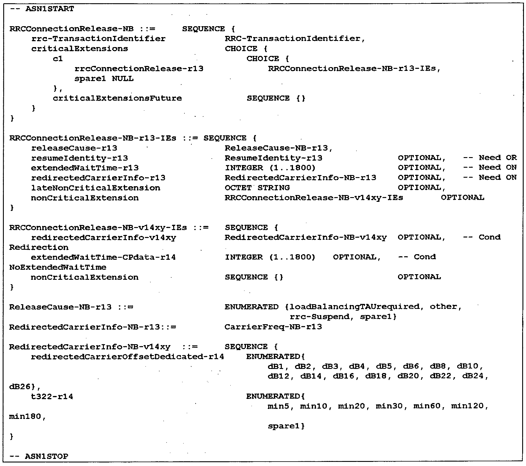
표 8과 같이, RRC Connection Release-NB 메시지는 RRCConnectionRelease-NB-v14xy-IEs 필드를 포함하고, 이 필드는 extendedWaitTime-CPdata-r14 필드를 포함한다. extendedWaitTime-CPdata-r14 필드는 1부터 1800까지의 값 중 하나로 지시될 수 있다.
아래 표 9 및 표 10은 RRC Connection Release-NB 메시지에 포함된 필드들의 설명한다.


CP CIoT EPS optimization을 위한 서비스 요청(Service request) 절차 개시
이하, TS 24.301에서 규정하는 service request 절차를 살펴본다.
UE는 다음과 같을 때 service request 절차를 호출(invoke)한다:
a) EMM-IDLE 모드인 UE가 네트워크로부터 "패킷 교환(PS: Packet Switched)"으로 셋팅된 CN 도메인 지시를 가지는 페이징 요청(paging request)을 수신할 때;
b) EMM-IDLE 모드인 UE가 전송될 대기 중인(pending) 사용자 데이터를 가질 때;
c) EMM-IDLE 모드인 UE가 대기 중인(pending) 상향링크 시그널링을 가질 때;
d) EMM-IDLE 모드 또는 EMM-CONNECTED 모드인 UE가 CS 폴백을 사용하도록 설정되고, UE가 상위 계층으로부터 수신된 단말 발생(originating) CS 폴백 요청을 가질 때;
e) EMM-IDLE 모드인 UE가 CS 폴백을 사용하도록 설정되고, 네트워크로부터 "CS"로 셋팅된 CN 도메인 지시를 가지는 페이징 요청(paging request)을 수신하거나, 또는 EMM-CONNECTED 모드인 UE가 CS 폴백을 사용하도록 설정되고 CS 서비스 통지(CS SERVICE NOTIFICATION) 메시지를 수신할 때;
f) EMM-IDLE 또는 EMM-CONNECTED 모드인 UE가 1xCS 폴백을 사용하도록 설정되고, 상위 계층으로부터 수신된 단말 발생(originating) 1xCS 폴백 요청을 가질 때;
g) EMM-CONNECTED 모드인 UE가 1xCS 폴백을 사용하도록 설정되고, E-UTRAN을 통해 수신된 1xCS 페이징 요청을 포함하는 cdma2000 시그널링 메시지를 수락할 때;
h) EMM-IDLE 모드인 UE가 E-UTRAN을 통해 전송될 대기 중인(pending) 상향링크 cdma2000 시그널링을 가질 때;
i) EMM-IDLE 또는 EMM-CONNECTED 모드인 UE가 1xCS 폴백을 사용하도록 설정되고, cdma2000 1xRTT를 통해 수신된 1xCS 페이징 요청을 포함하는 cdma2000 시그널링 메시지를 수락하고, 네트워크가 듀얼 Rx CSFB(Circuit Switched FallBack)을 지원하거나 CS 폴백 등록 파라미터를 제공할 때;
j) EMM-IDLE 또는 EMM-CONNECTED 모드인 UE가 cdma2000 1xRTT를 통해 전송될 대기 중인(pending) 상향링크 cdma2000 시그널링을 가지고, 네트워크가 듀얼 Rx CSFB을 지원하거나 CS 폴백 등록 파라미터를 제공할 때;
k) UE가 S101 모드로부터 S1 모드로 시스템 간(inter-system) 변경을 수행하고, 대기 중인(pending) 사용자 데이터를 가질 때;
l) EMM-IDLE 모드인 UE가 근접 서비스(ProSe: Proximity Service) 직접 디스커버리(direct discovery) 또는 ProSe 직접 통신(direct communication)을 위한 자원을 요청해야 할 때; 또는
m) EMM-CONNECTED 모드이고 NAS 시그널링 연결만을 가지는 UE가 control plane CIoT EPS optimization을 이용하는 EPS 서비스를 사용하고 있으며, 사용자 평면 무선 베어러를 통해 전송될 대기 중인(pending) 사용자 데이터를 가질 때; 또는
n) EMM-IDLE 모드인 UE가 PC5(UE 간 인터페이스)를 통한 V2X 통신을 위한 자원을 요청해야 할 때.
UE는 CONTROL PLANE SERVICE REQUEST 메시지를 전송하고, T3417를 시작하며, EMM-SERVICE-REQUEST-INITIATED 상태로 진입한다.
상기 a의 경우, CONTROL PLANE SERVICE REQUEST 메시지의 제어 평면 서비스 타입(Control plane service type)은 "발신 요청(mobile terminating request)"으로 셋팅한다. UE는 ESM 데이터 전달(ESM DATA TRANSPORT) 메시지를 포함시킬 수 있다. UE는 ESM 데이터 전달(ESM DATA TRANSPORT) 메시지 이외 다른 ESM 메시지를 포함시키지 않는다.
상기 b의 경우, UE가 제어 평면 무선 베어러를 통해 전송될 IP 또는 non-IP 사용자 데이터를 가지면, CONTROL PLANE SERVICE REQUEST 메시지의 Control plane service type은 "발신 요청(mobile terminating request)"으로 셋팅한다. UE는 ESM 메시지 컨테이너 IE 내 ESM DATA TRANSPORT 메시지를 포함시킨다.
상기 b 및 m의 경우, UE가 사용자 평면 무선 베어러를 통해 전송될 IP 또는 non-IP 사용자 데이터를 가지면, CONTROL PLANE SERVICE REQUEST 메시지의 Control plane service type은 "발신 요청(mobile terminating request)"으로 셋팅하고, Control plane service type IE 내 "active" 플래그를 1로 셋팅한다. UE는 CONTROL PLANE SERVICE REQUEST 메시지 내 어떠한 ESM 메시지 컨테이너 또는 NAS 메시지 컨테이너 IE를 포함시키지 않는다.
상기 c의 경우, UE는 CONTROL PLANE SERVICE REQUEST 메시지의 Control plane service type을 "발신 요청(mobile terminating request)"으로 셋팅한다. 만약, CONTROL PLANE SERVICE REQUEST가 다음과 같다면:
- SMS 전송을 위한 것이라면, UE는 NAS 메시지 컨테이너 IE 내 SMS 메시지를 포함시키고, CONTROL PLANE SERVICE REQUEST 메시지 내 어떠한 ESM 메시지 컨테이너 IE를 포함시키지 않는다; 그리고
- SMS와 상이한 시그널링을 전송하기 위한 것이라면, UE는 CONTROL PLANE SERVICE REQUEST 메시지 내 어떠한 ESM 메시지 컨테이너 또는 NAS 메시지 컨테이터 IE를 포함시키지 않는다.
제어 평면 서비스 요청(CPSR: Control Plane Service request) 메시지
이하, TS 24.301에서 규정하는 CPSR을 살펴본다.
표 11은 CPSR(CONTROL PLANE SERVICE REQUEST) 메시지를 예시한다.
이 메시지는 UE가 control plane CIoT EPS optimization을 이용하는 EPS 서비스를 사용할 때, UE에 의해 네트워크로 전송된다.

표 11을 참조하면, Protocol Discriminator는 3GPP TS 24.007 내 정의된다. 보안 보호되는 NAS 메시지의 헤더 내 Protocol discriminator는 "EPS 이동성 관리 메시지"로서 인코딩된다.
매 EPS 이동성 관리(EMM: EPS Mobility Management) 메시지의 첫 번째 옥텟의 5 내지 8번째 비트는 Security header type IE를 포함한다. 이 IE는 NAS 메시지의 보안 보호와 관련된 제어 정보를 포함한다. Security header type IE의 전체 크기는 4 비트이다.
Control plane service request message identity는 전달되는 NAS 메시지가 어떠한 메시지인지(즉, CPSR 메시지인지)를 식별하기 위해 이용된다.
제어 평면 서비스 타입(Control plane service type) IE는 CONTROL PLANE SERVICE REQUEST 메시지의 목적을 특정한다.
UE는 ESM 메시지를 네트워크에게 전송하길 원하면 ESM message container IE를 CPSR 메시지 내 포함시킨다. ESM message container IE의 목적은 EMM 메시지 내 단일의 ESM 메시지(즉, MO 데이터, ESM 데이터 전달(ESM data transport) 메시지)를 피기백(piggybacked)하여 전송할 수 있도록 하기 위함이다.
또한, UE가 EMM-IDLE 모드이고 전송될 대기 중인(pending) SMS 메시지를 가지면, UE는 NAS message container IE를 CPSR 메시지 내 포함시킨다.
또한, UE가 UE 내에서 활성화된 EPS 베어러 컨텍스트를 지시하길 원하면, UE는 EPS bearer context status IE를 CPSR 메시지 내 포함시킨다.
또한, UE가 NAS 시그널링 낮은 우선순위로 설정되면, UE는 Device properties IE를 CPSR 메시지 내 포함시킨다.
표 11에서 Control plane service type IE는 아래 표 12와 같이 코딩된다.

오버로드 제어(overload control) 방법
아래와 같이, 제어 평면(CP: Control Plane) 오버로드 제어와 관련하여 아래와 같은 합의/요구 사항이 규정되어 있다.
3GPP TS 23.401에서는 아래와 같이 규정하고 있다.
오버로드 시작(OVERLOAD START) 메시지를 이용하여, MME는 eNB에게 다음과 같이 요청할 수 있다:
- CP CIoT EPS Optimization만을 지원하는 UE로부터 "단말 발신 데이터(mo-data)" 또는 "지연 내성을 가지는 액세스(delayTolerantAccess)" 확립 원인(RRC establishment cause)을 가지는 RRC 연결 요청(RRC connection request)를 수락하지 않음
또한, 3GPP TS 36.413에서는 아래와 같이 규정하고 있다.
OVERLOAD START 메시지 내 오버로드 응답 정보(Overload Response) IE 내 오버로드 동작(Overload Action) IE는 CP CIoT EPS Optimization만을 지원하는 UE로부터 데이터 전송을 위한 RRC connection request를 수락하지 않도록(즉, "mo-data" 또는 "delayTolerantAccess" RRC 원인에 상응하는 트래픽을 수락하지 않음) 셋팅될 수 있다.
위의 규정에 따르면, eNB는 UE가 액세스를 위해 전송하는 RRC 메시지를 통해 다음의 정보를 파악하여 오버로드에 따른 CP 데이터에 대한 확장된 대기 시간(Extended wait timer for CP data)을 적용할지 여부를 결정해야 한다.
1) "mo-data" 또는 "delayTolerantAccess" RRC 확립 원인을 가지는 RRC connection request
2) CP CIoT EPS Optimization만을 지원하는 UE
위의 1)의 경우, 기존에 규정된 동작에 의해서, RRC connection request 메시지에 포함되어 전송되는 RRC 확립 원인을 통해 eNB가 파악할 수 있다.
하지만, 2)의 경우, 3GPP TS 36.331에 2.2.3.3절에 의하면, RA msg5(즉, RRC connection complete 메시지)에 포함되어 전송된다. 따라서, RA 메시지 5(msg5)까지 수신한 이후에, eNB는 CP 데이터에 대한 오버로드 제어를 적용할지 여부를 판단할 수 있다.
따라서, eNB는 RA 메시지 5(msg5)를 수신한 이후, CP 데이터에 대한 오버로드 제어를 적용할지 여부를 판단하고, 적용되는 경우, eNB는 RRC 해제(RRC release) 메시지 내에서 CP 데이터에 대한 확장된 대기 시간 타이머(extendedWaitTime-CPdata timer)를 포함시켜 UE의 AS 계층(즉, UE의 RRC 계층)에게 전송한다. 그리고, UE의 AS 계층은 UE의 NAS 계층에게 extendedWaitTime-CPdata timer를 전달한다. UE의 NAS 계층은 extendedWaitTime-CPdata timer 값을 T3446(즉, CP 백-오프 타이머)에 적용하여 동작할 것으로 예상된다.
이러한 동작과 관련하여, RRC 원인 "mo-data" 및 "delayTolerantAccess" 둘 다 CP CIoT EPS Optimization만을 지원하는 UE로부터의 RRC connection request를 거절하기 위해 eNB에 의해 사용될 수 있으므로, 다음과 같은 문제가 제기되었다.
(1) RRC 원인 "mo-data" 및 "delayTolerantAccess" 둘 다 eNB의 CP 데이터의 오버로드 제어를 위해 사용된다면(즉, eNB가 RRC 확립 원인 "mo-data" 또는 "delayTolerantAccess"를 포함하는 RRC connection request 메시지를 RRC Connection Reject 메시지로 거절한다면), eNB는 CP CIoT EPS Optimization만을 지원하고 NAS 시그널링 낮은 우선순위(low priority)로 설정된 UE에 의해 개시되는 모든 RRC Connection Request를 거절하게 될 것이다. 결과적으로 모든 초기 NAS 절차가 실패될 수 있다는 문제가 있다.
(2) (1)의 논의에 따라, 만약 "mo-data"만이 CP 데이터를 위한 오버로드 제어를 위해 eNB에 의해 사용된다면(즉, eNB가 RRC 확립 원인 "mo-data"를 포함하는 RRC connection request 메시지만을 RRC Connection Reject 메시지로 거절한다면), CP CIoT EPS Optimization만을 지원하고 NAS 시그널링 낮은 우선순위(low priority)로 설정된 UE는 eNB에서 CP 데이터를 위한 오버로드 제어가 처리되지 않을 수 있다.
하지만, 현재 3GPP 규정에 따르면, eNB가 RRC 연결 거절(RRC connection reject)을 수행하지 않으며, RRC 연결 해제(RRC connection release)을 수행하도록 규정되어 있으므로, 위의 (1)은 현재 3GPP 규정과 맞지 않다.
구체적으로 살펴보면, RRC 확립 원인은 RA 제3 메시지(msg3)(즉, RRC connection request 메시지)에 포함되어 전송되고, CP CIoT EPS optimization의 지원 또는 UP CIoT EPS optimization 지원 또는 둘 모두 지원에 대한 정보는 RA 제5 메시지(msg5)(즉, RRC connection setup complete 메시지)에 포함되어 전송된다.
따라서, eNB는 RRC 확립 원인을 RA msg3를 통해서 파악할 수 있고, CP CIoT EPS optimization만을 지원하는지 여부는 RA msg5를 통하여 파악할 수 있다. 그리고, 이를 기반으로 eNB은 CP 오버로드 제어를 적용할지 여부를 판단한다. 적용하는 경우, eNB는 RRC connection release 메시지 내 CP 데이터에 대한 확장된 대기 시간 타이머(extendedWaitTime-CPdata timer)를 포함하여 전송한다.
즉, 앞서 제기된 문제는 기술에 대한 이해 부족으로 잘못된 내용이 기술되었다.
문제점 1)
기존의 UE의 NAS 계층의 동작에 따르면, UE의 NAS 계층은 다음과 같이 CIoT EPS optimization의 사용 요청을 하위 계층에게 전달한다.
- NB-S1 모드에서, UE가 하위 계층에게 RRC 연결을 확립하도록 요청하고, UE가 EMM-REGISTERED without PDN connection 또는 user plane CIoT EPS optimization의 사용을 요청할 때, UE는 요청된 CIoT EPS optimization(들)의 지시를 하위 계층에게 전달한다. UE가 user plane CIoT optimization 없이 S1-U 데이터 전달의 사용을 요청하면, UE는 또한 user plane CIoT EPS optimization의 지시를 하위 계층에게 전달한다.
- WB-S1 모드에서, UE가 하위 계층에게 RRC 연결의 확립을 요청하고, EMM-REGISTERED without PDN connection, control plane CIoT EPS optimization 또는 user plane CIoT EPS optimization의 사용을 요청할 때, UE는 요청된 CIoT EPS optimization(들)의 지시를 하위 계층에게 전달한다.
위와 같은 동작은, 다음과 같이 attach 절차 또는 TAU 절차 중에 수행된다.
- CIoT EPS optimizations을 지원하는 UE는 attach 또는 TAU 절차 동안에 UE가 지원하고 사용하길 원하는 CIoT 네트워크 동작을 지시할 수 있다. 선호의 지시는 또한 사용의 요청으로서 간주된다.
- attach 또는 TAU 절차 동안에 CIoT EPS optimizations의 사용을 요청할 때, UE는 NB-S1 모드 또는 WB-S1 모드일 수 있다.
결국, 서비스 요청(service request) 절차 동작 시, UE는 사용을 요청하는 CIoT EPS optimization 관련 정보를 하위 계층에게 전달하지 않는다.
CP 오버헤드 제어에 의하면, 다음의 두 가지 메시지(즉, "signalling active" 플래그(이 플래그는 UE가 CP CIoT EPS optimization을 이용하는 EPS 서비스만을 사용하길 원할 때 '1'로 셋팅됨)를 포함하는 TAU request 및 ESM Data Transport 메시지가 피기백된(piggybacked) Control Plane Service Request)를 eNB가 구분하여 오버로드 제어를 적용할지 여부를 판단하여야 한다.
CP 데이터를 위한 코어 네트워크 오버로드 제어는 CP를 통한 데이터 전송에 대한 UE로부터의 요청(즉, "signalling active" 플래그를 포함하는 TAU request, ESM Data Transport 메시지가 피기백된(piggybacked) Control Plane Service Request)을 제한하기 위함이다. 따라서, 다른 NAS 시그널링 메시지(예를 들어, attach request 메시지, "signalling active" 플래그가 없는 TAU request) 및 서비스(예를 들어, SMS)는 여전히 허용된다.
하지만, 상술한 바와 같이, Service request 절차 동작 시에는 UE가 사용을 요청할 CIoT EPS optimization 관련 정보를 하위 계층에게 전달하지 않기 때문에, eNB는 ESM Data Transport 메시지가 피기백된(piggybacked) CP service request로부터 UE가 CP CIoT EPS Optimization만을 지원하는 UE인지 여부를 파악할 수 없는 문제가 있다. 즉, 기존의 동작에 따르면, ESM Data Transport 메시지가 피기백된(piggybacked) CP service request에 대하여 CP를 위한 오버로드 제어를 적용할 수 없다는 문제가 발생한다.
문제점 2)
종래 기술에 따르면, TAU 절차 도중에 UE의 NAS 계층은 CIoT EPS optimization을 사용을 요청(request the use of CIoT EPS optimization)하는 지시를 하위 계층에게 전달(pass)한다. 이 지시를 수신한 UE의 AS 계층(UE의 RRC 계층)은 해당 정보를 RA msg5(RRC connection setup complete 메시지)에 포함하여 eNB로 전송한다. 상술한 바와 같이, eNB는 RA msg5에 포함된 그 정보를 바탕으로 CP를 위한 오버로드 제어를 적용할지 여부를 결정한다.
CP를 위한 오버로드 제어는 다음과 같은 두 가지 message에 대해서 적용된다.
- "signalling active" 플래그를 포함하는 TAU request; 및
- ESM Data Transport 메시지가 피기백된(piggybacked) Control Plane Service Request
종래 동작에 따르면 TAU request 메시지 전송 시, CIoT EPS optimization을 사용을 요청 (request the use of CIoT EPS optimization)하는 지시가 하위 계층에게 전달되고, 이 정보가 eNB로 전달되기 때문에 eNB는 UE가 CP CIoT EPS optimization만을 지원하는지 확인할 수 있다. 하지만, TAU request message의 종류는 여러 가지가 존재한다.
- 어떠한 플래그도 없는 TAU request 메시지
- "액티브(active)" 플래그를 포함하는 TAU request 메시지
- "signalling active" 플래그를 포함하는 TAU request 메시지
eNB는 MME로부터 CP를 위한 overload start 메시지를 수신한 경우, 상기 TAU 메시지 중 "signalling active" 플래그를 포함하는 TAU request 메시지에만 CP를 위한 오버로드 제어를 적용해야 한다. 하지만, 종래 CIoT EPS optimization을 사용을 요청을 하는 동작은 상기 모든 TAU request 메시지에 적용되기 때문에, eNB는 이 중 "signalling active" 플래그를 포함하는 TAU request 메시지에만 구분할 수가 없다는 문제가 발생한다.
다시 말해, UE는 TAU request 메시지 전송 시, MME 선택을 위해서 CIoT EPS optimization를 사용을 요청(request the use of CIoT EPS optimization)하는 동작을 반드시 수행해야 한다. 즉, 모든 TAU request 메시지 전송 시, CIoT EPS optimization에 대한 사용 요청에 대한 지시가 하위 계층에게 전달을 전달되어야 하기 때문에, 이러한 지시는 CP CIoT EPS optimization을 "signalling active" 플래그를 포함하는 TAU request 메시지와 다른 TAU request 메시지를 구분하기 위한 구분자로 사용할 수 없는 문제가 있다.
위와 같은 문제점을 해결하기 위해, 본 발명에서는 제어 평면 오버로드 제어를 지원하기 위한 UE와 eNB의 동작을 제안한다.
다음은 EPC에서 사용하던 용어가 5G 시스템에서 사용되는 용어와의 매핑 관계를 예시한다.
- eNB: gNB
- MME: 이동성 관리 기능(AMF: access and mobility management function) (또는 세션 관리 기능(SMF: Session Management Function))
- MME-EMM (EMM 계층): AMF (5GMM(5G Mobility Management) 계층)
- MME-ESM (ESM 계층): SMF (5GSM(5G Session Management 계층)
- S-GW 사용자 평면 기능 / P-GW 사용자 평면 기능: 사용자 평면 기능(UPF: User Plane Function) (계층)
- S1AP (인터페이스/메시지): N2 (인터페이스/메시지)
- NAS (시그널링 연결/인터페이스): N1 (연결/인터페이스)
또한, 5G 시스템에서 MME-EMM은 AMF와 매핑되고, MME-ESM는 SMF와 매핑되고, MME-EMM과 MME-AMF사이의 인터페이스는 N11로 매핑되고, MME-EMM과 eNB 사이의 인터페이스는 N2로 매핑된다.
따라서, 앞서 설명한 매핑 관계에 따라 이하 본 발명의 설명을 대체함으로써, 이하 본 발명에 대한 설명이 5G 시스템에서도 동일한 방식으로 적용될 수 있다.
[실시예 1]
앞서 CP CIoT EPS optimization을 위한 service request 절차 개시에 대한 설명에서, UE의 NAS 계층이 제어 평면 서비스 요청(CPSR: Control Plane Service Request) 메시지를 전송하는 경우들에 대해서 기술하고 있다. TS 24.301의 5.6.1.1절에 service request 절차의 트리거링 조건 중 다음과 같은 세 가지 경우가 CPSR를 전송하는 경우에 관련되어 있다.
a) EMM-IDLE 모드인 UE가 네트워크로부터 "PS"으로 셋팅된 CN 도메인 지시를 가지는 페이징 요청(paging request)을 수신할 때;
b) EMM-IDLE 모드인 UE가 전송될 대기 중인(pending) 사용자 데이터를 가질 때;
c) EMM-IDLE 모드인 UE가 대기 중인(pending) 상향링크 시그널링을 가질 때;
위에서 a)는 착신(MT: mobile terminated) 응답에 관한 경우이다. CP 오버로드 제어는 mo data와 delaytolerantAccess만 적용하므로 MT 응답의 경우인 a)는 CP overload control과는 관련이 없다.
상기에서 b)의 경우는 CPSR 의 형태가 아래와 같이 두 가지 경우로 나뉜다.
- 제어 평면 무선 베어러로 전송할 데이터가 있는 경우, CPSR은 ESM 데이터 전달(ESM data transport) 메시지가 포함된 ESM 메시지 컨테이너(ESM message container) IE를 포함한다.
- 사용자 평면 무선 베어러로 전송할 데이터가 있는 경우, CPSR은 제어 평면 서비스 타입(control planer service type) IE의 "active" 플래그를 1로 하고, ESM 데이터 전달(ESM data transport) 메시지를 포함하지 않는다.
상기에서 c)의 경우는 CPSR 의 형태가 아래와 같이 두 가지 경우로 나뉜다.
- SMS를 전송하는 경우, CPSR은 NAS 메시지 컨테이너(NAS message container) IE에 SMS 메시지를 포함하고, ESM 메시지 컨테이너(ESM message container) IE를 포함하지 않는다.
- SMS와 다른 시그널링을 전송하는 경우, CPSR은 ESM 데이터 전달(ESM data transport) 메시지와 NAS 메시지 컨테이너(NAS message container) IE를 포함하지 않는다.
이하, UE의 동작에 대하여 살펴본다.
[방법 1] 종래 Control Plane CIoT EPS optimization의 사용 요청을 이용하는 방법
케이스 A)
다음과 같은 경우, UE의 NAS 계층은 Control Plane CIoT EPS optimization만 사용할 것을 요청(request the use of Control Plane CIoT EPS optimization only)하는 지시를 하위 계층에게 전달(pass)한다. 즉, 제어 평면을 통한 데이터의 전송을 지시하기 위한 지시로서 Control Plane CIoT EPS optimization만을 사용할 것을 요청하는 지시가 이용될 수 있다. 특히, UE가 NB-IoT UE의 경우(즉, UE가 NB-IoT RAT을 이용하는 UE)인 경우에만, 제어 평면을 통한 데이터의 전송을 지시하기 위한 지시로서 Control Plane CIoT EPS optimization의 사용을 요청하는 지시가 이용될 수도 있다.
- 제어 평면 무선 베어러로 전송할 데이터가 있는 경우, CPSR은 ESM 데이터 전달(ESM data transport) 메시지가 포함된 ESM 메시지 컨테이너(ESM message container) IE를 포함한다.
위의 경우에서, Control Plane CIoT EPS optimization만의 사용 요청은 User plane CIoT EPS optimization에 대한 사용 요청(request the use)을 포함하지 않으며, Control Plane CIoT EPS optimization에 대한 사용 요청(request the use)만 포함하는 경우를 의미한다.
케이스 B)
다음과 같은 경우, UE의 NAS 계층은 Control Plane CIoT EPS optimization만을 사용할 것을 요청(request the use of Control Plane CIoT EPS optimization only)하는 지시를 하위 계층에게 전달(pass)하지 않는다.
1. 사용자 평면 무선 베어러로 전송할 데이터가 있는 경우, CPSR은 제어 평면 서비스 타입(control plane service type) IE의 "active" 플래그를 1로 하고, ESM 데이터 전달(ESM data transport) 메시지를 포함하지 않는다.
이때, UE의 NAS 계층은 User plane CIoT EPS optimization만을 사용할 것을 요청(request the use of User Plane CIoT EPS optimization only)하는 지시를 하위 계층에게 전달(pass)할 수 있다.
2. SMS를 전송하는 경우, CPSR은 NAS 메시지 컨테이너(NAS message container) IE에 SMS 메시지를 포함하고, ESM message container IE를 포함하지 않는다.
3. SMS와 다른 시그널링을 전송하는 경우, CPSR은 ESM 데이터 전달(ESM data transport) 메시지와 NAS 메시지 컨테이너(NAS message container) IE를 포함하지 않는다.
[방법 2]
앞서 설명한 케이스 A) 또는 케이스 B)의 내용을 구현하는 다른 예로서 다음과 같은 방법을 생각할 수 있다.
[방법 2-1]
앞서 설명한 케이스 A)와 케이스 B)의 경우, UE의 NAS 계층은 기존의 CIoT EPS optimization을 사용할 것을 요청(request the use of CIoT EPS optimization)하는 지시와는 별도의(상이한) 지시(즉, 제어 평면을 통한 데이터의 전송을 지시하기 위한 지시)를 하위 계층에게 전달할 수 있다.
상기 지시를 UE의 AS 계층(예를 들어, UE의 RRC 계층)이 수신하면, UE의 AS 계층은 해당 지시를 RA msg5(즉, RRC connection setup complete 메시지)에 'CIoT EPS optimization을 사용할 것을 요청(request the use of CIoT EPS optimization)하는 지시'와는 별도의(상이한) 지시를 포함시켜 eNB에게 전송한다.
상기 지시는 케이스 A)의 경우, 'CP CIoT EPS Optimization을 통한 데이터 전송(data transfers via Control Plane CIoT EPS Optimization)'이거나 또는 'CP 데이터'일 수 있다. 즉, 제어 평면을 통한 데이터의 전송을 지시하기 위한 지시에 해당될 수 있다.
또한, 케이스 B-1)의 경우, 'UP CIoT EPS Optimization을 통한 데이터 전송(data transfers via User Plane CIoT EPS Optimization)'이거나 또는 'UP 데이터'일 수 있다. 즉, 사용자 평면을 통한 데이터의 전송을 지시하기 위한 지시에 해당될 수 있다.
[방법 2-2]
[방법 2-1]에서 기술된 지시는 종래 CIoT EPS optimization에 대한 지시의 또 다른 한 종류의 형태로 Msg5 내 포함되어 사용될 수 있다. 즉, 'Control plane CIoT EPS optimization'이면 제어 평면을 통한 데이터 전송과 무관한 Control plane CIoT EPS optimization을 의미하고, 'Control Plane CIoT EPS Optimization를 통한 데이터 전송'(즉, 즉, 제어 평면을 통한 데이터의 전송을 지시하기 위한 지시)은 제어 평면을 통한 데이터 전송과 관련된 Control plane CIoT EPS optimization을 의미할 수 있다.
상기 내용을 지원하기 위한 UE의 동작은 다음과 같다.
UE의 NAS 계층이 CPSR에 ESM 데이터 전달(ESM data transport) 메시지가 포함된 ESM 메시지 컨테이너(ESM message container) IE를 포함하는 경우(즉, 케이스 A의 경우), 'Control Plane CIoT EPS Optimization을 통한 데이터 전송(또는 CP 데이터)'의 사용 요청 지시를 하위 계층에게 전달한다.
UE의 NAS 계층이 사용자 평면 무선 베어러로 전송할 data가 있는 경우, CPSR은 제어 평면 서비스 타입(control planer service type) IE의 "active" 플래그를 1로 설정하는 경우(즉, 케이스 B-1의 경우), 'User Plane CIoT EPS Optimization을 통한 데이터 전송(또는 UP 데이터)'의 사용 요청 지시를 하위 계층에게 전달한다.
UE의 NAS 계층은 CPSR 전송 중 위에서 언급한 경우를 제외하고, 'Control plane CIoT EPS optimization' 사용 요청 지시를 하위 계층에게 전달한다.
상술한 지시를 수신한 UE의 AS 계층(예를 들어, UE의 RRC 계층)은 해당 지시를 RA msg5(즉, RRC connection setup complete 메시지)에 포함하여 eNB에게 전송한다.
앞서 설명한 [방법 1]은 WB-S1 모드인 경우, 그대로 적용될 수 있다. 하지만, NB-S1 모드에서는 Control plane CIoT EPS optimization이 필수적이다. 따라서, UE의 NAS 계층은 Control plane CIoT EPS optimization에 대한 사용 요청(request the use of Control plane CIoT EPS optimization)을 하위 계층에게 전달(pass)하지 않는다. 그러므로, [방법 1]을 적용하기 위해서는 NB-S1 모드에서도 UE의 NAS 계층이 Control plane CIoT EPS optimization에 대한 사용 요청(request the use of Control plane CIoT EPS optimization)을 하위 계층에게 전달(pass)하고, 이를 수신한 UE의 AS 계층(예를 들어, UE의 RRC 계층)가 RA msg5(즉, RRC connection setup complete 메시지)에 이 지시를 추가하는 동작을 가능하도록 할 필요가 있다.
[방법 2]의 경우, WB-S1 모드와 NB-S1 모드에 그대로 적용이 가능하다.
이하, eNB의 동작에 대하여 살펴본다.
eNB가 MME로부터 CP CIoT EPS optimization를 통한 데이터 전송에 대한 오버로드 제어 정보를 포함한 overload start 메시지를 수신한 경우, eNB가 앞서 설명한 지시를 수신하면, 하기와 같이 동작한다.
[방법 1]을 적용 시:
eNB는 Control Plane CIoT EPS Optimization만을 지원하는 UE로부터 RRC 확립 원인 "mo-data" 또는 "delayTolerantAccess"를 포함하는 RRC connection request를 수락하지 않는다.
이 경우, eNB는 RRC connection release 메시지에 extendedWaitTime-CPdata를 포함하여 UE에게 전송한다. 이를 수신한 UE의 AS 계층(예를 들어, UE의 RRC 계층)은 해당 extendedWaitTime-CPdata를 UE의 NAS 계층으로 전달한다. UE의 NAS 계층은 extendedWaitTime-CPdata를 T3446에 적용한다(즉, extendedWaitTime-CPdata 값으로 T3446 타이머를 시작한다).
[방법 2] 적용 시:
eNB는 'Control Plane CIoT EPS Optimization을 통한 데이터 전송(또는 CP 데이터)'을 지시하는 UE로부터 RRC 확립 원인 "mo-data" 또는 "delayTolerantAccess"를 포함하는 RRC connection request를 수락하지 않는다.
이 경우, eNB는 RRC connection release 메시지에 extendedWaitTime-CPdata를 포함하여 UE에게 전송한다. 이를 수신한 UE의 AS 계층(예를 들어, UE의 RRC 계층)은 해당 extendedWaitTime-CPdata를 UE의 NAS 계층으로 전달한다. UE의 NAS 계층은 extendedWaitTime-CPdata를 T3446에 적용한다(즉, extendedWaitTime-CPdata 값으로 T3446 타이머를 시작한다).
앞서 설명한 [방법 2]에서 지시가 종래 CIoT EPS optimization에 대한 지시의 또 다른 IE 형태로 포함되어 사용 되는 경우(즉, [방법 2-1]을 적용하는 경우), eNB는 추가적으로 다음과 같이 동작한다.
eNB는 UE로부터 'Control Plane CIoT EPS Optimization을 통한 데이터 전송(또는 CP 데이터)'을 수신하면, 종래 'Control Plane CIoT EPS optimization'이 나타내는 Control plane CIoT EPS optimization의 사용을 요청하는 의미와 더불어 Control Plane CIoT EPS optimization을 통해서 데이터를 전송한다는 의미로 이해할 수 있다. 전자의 의미는 종래와 같이 MME 선택 시 사용하고, 후자의 의미는 CP 오버로드 제어 적용 시 사용할 수 있다.
[실시예 2]
이하, UE의 동작에 대하여 살펴본다.
'signalling active' 플래그를 포함하는 TAU request 메시지를 전송하는 경우 UE는 하기와 같이 동작한다.
[방법 1]
UE의 NAS 계층은 기존의 'CIoT EPS optimization을 사용할 것을 요청(request the use of CIoT EPS optimization)하는 indication'과는 별도의(상이한) 지시를 하위 계층에게 전달할 수 있다.
상기 지시(즉, 별도의(상이한) 지시)를 UE의 AS 계층(예를 들어, UE의 RRC 계층)이 수신하면, UE의 AS 계층은 해당 지시를 RA msg5(즉, RRC connection setup complete 메시지)에 'CIoT EPS optimization을 사용할 것을 요청(request the use of CIoT EPS optimization)하는 지시'와는 별도의(상이한) 지시를 포함시켜 eNB에게 전송한다.
상기 지시(즉, 별도의(상이한) 지시)는 'CP CIoT EPS Optimization을 통한 데이터 전송(data transfers via Control Plane CIoT EPS Optimization)'이거나 또는 'CP 데이터'일 수 있다.
[방법 2]
[방법 1]에 기술된 지시는 종래 CIoT EPS optimization에 대한 지시의 또 다른 한 종류의 형태로 Msg5 내 포함되어 사용될 수 있다. 즉, 'Control plane CIoT EPS optimization'이면 제어 평면을 통한 데이터 전송과 무관한 Control plane CIoT EPS optimization을 의미하고, 'Control Plane CIoT EPS Optimization를 통한 데이터 전송'은 제어 평면을 통한 데이터 전송과 관련된 Control plane CIoT EPS optimization을 의미할 수 있다.
상기 내용을 지원하기 위한 UE의 동작은 다음과 같다.
UE의 NAS 계층이 'signalling active' 플래그를 포함하는 TAU request 메시지를 전송하는 경우, UE의 NAS 계층은 'Control Plane CIoT EPS Optimization을 통한 데이터 전송(또는 CP 데이터)'의 사용 요청 지시를 하위 계층에게 전달한다.
TAU request 메시지 전송 중 위의 경우를 제외하고, UE의 NAS 계층은 'Control plane CIoT EPS optimization' 사용 요청 지시를 하위 계층에게 전달한다.
상술한 지시를 수신한 UE의 AS 계층(예를 들어, UE의 RRC 계층)은 해당 지시를 RA msg5(즉, RRC connection setup complete 메시지)에 포함하여 eNB에게 전송한다.
다른 TAU request 메시지(즉, 어떠한 플래그도 없는 TAU request 메시지 또는 'active' 플래그를 포함하는 TAU request 메시지)의 경우, 앞서 설명한 지시와 관련된 동작이 수행되지 않을 수 있다. 또는, 'active' 플래그를 포함하는 TAU request 메시지의 경우, 'User Plane CIoT EPS Optimization을 통한 데이터 전송' 또는 'UP 데이터' 지시를 사용할 수도 있다.
이하, eNB의 동작에 대하여 살펴본다.
eNB가 MME로부터 CP CIoT EPS optimization를 통한 데이터 전송에 대한 오버로드 제어 정보를 포함한 overload start 메시지를 수신한 경우, eNB가 앞서 설명한 지시를 수신하면, 하기와 같이 동작한다.
[방법 1과 방법 2 공통]
eNB는 'Control Plane CIoT EPS Optimization을 통한 데이터 전송(또는 CP 데이터)'를 지시하는 UE로부터 RRC 확립 원인 "mo-data" 또는 "delayTolerantAccess"를 포함하는 RRC connection request를 수락하지 않는다.
이 경우, eNB는 RRC connection release 메시지에 extendedWaitTime-CPdata를 포함하여 UE에게 전송한다. 이를 수신한 UE의 AS 계층(예를 들어, UE의 RRC 계층)은 해당 extendedWaitTime-CPdata를 UE의 NAS 계층으로 전달한다. UE의 NAS 계층은 extendedWaitTime-CPdata를 T3446에 적용한다(즉, extendedWaitTime-CPdata 값으로 T3446 타이머를 시작한다).
상기 지시가 종래 CIoT EPS optimization에 대한 지시의 또 다른 IE 형태로 포함되어 사용 되는 경우(즉, [방법 2]을 적용하는 경우), eNB는 추가적으로 다음과 같이 동작한다.
eNB는 UE로부터 'Control Plane CIoT EPS Optimization을 통한 데이터 전송(또는 CP 데이터)'을 수신하면, 종래 'Control Plane CIoT EPS optimization'이 나타내는 Control plane CIoT EPS optimization의 사용을 요청하는 의미와 더불어 Control Plane CIoT EPS optimization을 통해서 데이터를 전송한다는 의미로 이해할 수 있다. 전자의 의미는 종래와 같이 MME 선택 시 사용하고, 후자의 의미는 CP 오버로드 제어 적용 시 사용할 수 있다.
도 10은 본 발명의 일 실시예에 따른 오버로드 제어 방법을 예시하는 도면이다.
도 10을 참조하면, 기지국은 코어 네트워크(예를 들어, MME 또는 AMF 또는 SMF)로부터 오버로드 시작(overload start) 메시지를 수신한다(S1001).
여기서, 오버로드 시작(overload start) 메시지는 해당 코어 네트워크로 향하여 시그널링 로드를 감소시키기 위하여 오버로드 시작(제어) 절차가 시작되었음을 알리기 위하여 이용될 수 있다.
기지국은 UE로부터 제1 RRC 메시지를 수신한다(S1002).
여기서, 제1 RRC 메시지는 RRC 연결 셋업 완료(RRC Connection Setup Complete)일 수 있다.
또한, 제1 RRC 메시지는 NAS 메시지 및/또는 제어 평면을 통한 데이터의 전송을 지시하기 위한 지시를 포함할 수 있다.
앞서 설명한 바와 같이, 이 지시는 앞서 실시예 1의 방법 1에서 기술한 CP CIoT EPS optimization만의 사용을 요청하는 지시(request the use of Control Plane CIoT EPS optimization only)가 이용될 수 있다. 특히, UE가 NB-IoT UE의 경우(즉, UE가 NB-IoT RAT을 이용하는 UE)인 경우에만, 제어 평면을 통한 데이터의 전송을 지시하기 위한 지시로서 Control Plane CIoT EPS optimization만의 사용을 요청하는 지시가 이용될 수도 있다.
또한, 앞서 설명한 실시예 1의 방법 2, 실시예 2에서 기술한 Control Plane CIoT EPS optimization의 사용을 요청하는 지시와 상이한(별도의) 지시가 이용될 수도 있다. 만약, 앞서 설명한 실시예 1의 방법 2-2, 실시예 2의 방법 2에서 기술한 지시가 이용되는 경우, 이 지시는 제어 평면 CIoT EPS 최적화의 사용 요청과 함께 제어 평면 CIoT EPS 최적화를 통한 데이터 전송으로 간주될 수 있다.
한편, 상기 지시는 UE가 CP CIoT EPS optimization만을 사용할 때에만 상기 제1 RRC 메시지에 포함될 수도 있다.
또한, 제1 RRC 메시지에 포함되는 NAS 메시지는 MO 데이터를 포함하는 제어 평면 서비스 요청(Control Plane Service Request) 메시지일 수 있다. 즉, ESM 데이터 전달(ESM data transport) 메시지(MO 데이터)를 피기백(piggybacked)하여 전송하기 위한 ESM message container IE를 포함하는 Control Plane Service Request 메시지일 수 있다. 또는, 제1 RRC 메시지에 포함되는 NAS 메시지는 시그널링 액티브(signaling active) 플래그를 포함하는 TAU 요청 메시지일 수 있다.
만약, 제1 RRC 메시지가 제어 평면을 통한 데이터의 전송을 지시하기 위한 지시를 포함하면, 기지국은 RRC 연결의 해제를 명령하기 위한 RRC 연결 해제(RRC connection release) 메시지를 UE에게 전송한다(S1003).
여기서, RRC connection release 메시지는 CP를 통한 사용자 데이터 접속을 위한 대기 시간(예를 들어, extendedWaitTime-CPdata)를 포함할 수 있다.
이를 수신한 UE는 대기 시간을 백-오프(back-off) 타이머에 적용(즉, 수신한 대기 시간으로 백-오프 타이머를 시작)할 수 있다.
한편, 기지국이 수신한 상기 오버로드 시작(overload start) 메시지 내 IE(예를 들어, 오버로드 응답(Overload Response) IE 내 오버로드 액션(Overload Action) IE)가 CP CIoT EPS Optimization만을 지원하는 UE로부터 데이터 전송을 위한 RRC 연결 요청을 수락하지 않는다고 셋팅(즉, RRC 원인 "mo-data" 또는 "mo-signaling" 또는 "delayTolerantAccess"에 상응하는 트래픽을 수락하지 않음)되었을 때, 오버로드 제어 동작이 수행될 수 있다.
기지국은 제1 RRC 메시지를 수신하기 이전에 UE로부터 발신(MO: Mobile Originated) 데이터(mo-data) 또는 발신-시그널링(mo-signaling) 또는 지연 내성이 강한 접속(delayTolerantAccess)의 RRC 확립 원인(establishment cause)을 포함하는 제2 RRC 메시지를 수신하고, 앞서 설명한 지시를 포함하는 제1 RRC 메시지를 수신할 수 있다. 여기서, 제2 RRC 메시지는 RRC 연결 요청(connection request) 메시지일 수 있다. 기지국은 위와 같은 RRC 확립 원인을 포함하는 제2 RRC 메시지를 수신하고, 그리고 앞서 설명한 지시를 포함하는 제1 RRC 메시지를 수신하면, RRC connection release 메시지를 UE에게 전송할 수 있다.
도 11은 본 발명의 일 실시예에 따른 오버로드 제어 방법을 예시하는 도면이다.
도 11을 참조하면, UE의 NAS 계층은 제어 평면을 통한 데이터의 전송을 지시하기 위한 지시 및 NAS 메시지를 UE의 AS 계층에게 전달한다(S1101).
앞서 설명한 바와 같이, 이 지시는 앞서 실시예 1의 방법 1에서 기술한 CP CIoT EPS optimization만의 사용을 요청하는 지시(request the use of Control Plane CIoT EPS optimization only)가 이용될 수 있다. 특히, UE가 NB-IoT UE의 경우(즉, UE가 NB-IoT RAT을 이용하는 UE)인 경우에만, 제어 평면을 통한 데이터의 전송을 지시하기 위한 지시로서 Control Plane CIoT EPS optimization만의 사용을 요청하는 지시가 이용될 수도 있다.
또한, 앞서 설명한 실시예 1의 방법 2, 실시예 2에서 기술한 Control Plane CIoT EPS optimization의 사용을 요청하는 지시와 상이한(별도의) 지시가 이용될 수도 있다. 만약, 앞서 설명한 실시예 1의 방법 2-2, 실시예 2의 방법 2에서 기술한 지시가 이용되는 경우, 이 지시는 제어 평면 CIoT EPS 최적화의 사용 요청과 함께 제어 평면 CIoT EPS 최적화를 통한 데이터 전송으로 간주될 수 있다.
한편, 상기 지시는 UE가 CP CIoT EPS optimization만을 사용할 때에만 상기 제1 RRC 메시지에 포함될 수도 있다.
또한, 제1 RRC 메시지에 포함되는 NAS 메시지는 MO 데이터를 포함하는 제어 평면 서비스 요청(Control Plane Service Request) 메시지일 수 있다. 즉, ESM 데이터 전달(ESM data transport) 메시지(MO 데이터)를 피기백(piggybacked)하여 전송하기 위한 ESM message container IE를 포함하는 Control Plane Service Request 메시지일 수 있다. 또는, 제1 RRC 메시지에 포함되는 NAS 메시지는 시그널링 액티브(signaling active) 플래그를 포함하는 TAU 요청 메시지일 수 있다.
UE의 AS 계층은 상기 지시 및 상기 NAS 메시지를 포함하는 제1 RRC 메시지를 기지국에게 전송한다(S1102).
여기서, 제1 RRC 메시지는 RRC 연결 셋업 완료(RRC Connection Setup Complete)일 수 있다.
UE의 AS 계층이 기지국으로부터 CP를 통한 사용자 데이터 접속을 위한 대기 시간을 포함하는 RRC 연결 해제(RRC connection release) 메시지를 수신하면(S1103), 대기 시간을 UE의 NAS 계층에게 전달한다(S1104).
UE의 NAS 계층은 대기 시간을 백-오프(back-off) 타이머에 적용(즉, 수신한 대기 시간으로 백-오프 타이머를 시작)한다(S1105).
한편, 기지국이 코어 네트워크로부터 수신한 오버로드 시작(overload start) 메시지 내 IE(예를 들어, 오버로드 응답(Overload Response) IE 내 오버로드 액션(Overload Action) IE)가 CP CIoT EPS Optimization만을 지원하는 UE로부터 데이터 전송을 위한 RRC 연결 요청을 수락하지 않는다고 셋팅(즉, RRC 원인 "mo-data" 또는 "mo-signaling" 또는 "delayTolerantAccess"에 상응하는 트래픽을 수락하지 않음)되었을 때, 오버로드 제어 동작이 수행될 수 있다.
UE의 AS 계층은 제1 RRC 메시지를 전송하기 이전에 발신(MO: Mobile Originated) 데이터(mo-data) 또는 발신-시그널링(mo-signaling) 또는 지연 내성이 강한 접속(delayTolerantAccess)의 RRC 확립 원인(establishment cause)을 포함하는 제2 RRC 메시지를 기지국에게 전송하고, 앞서 설명한 지시를 포함하는 제1 RRC 메시지를 전송할 수 있다. 여기서, 제2 RRC 메시지는 RRC 연결 요청(connection request) 메시지일 수 있다. 이 경우, 기지국은 위와 같은 RRC 확립 원인을 포함하는 제2 RRC 메시지를 수신하고, 그리고 앞서 설명한 지시를 포함하는 제1 RRC 메시지를 수신하면, RRC connection release 메시지를 UE에게 전송할 수 있다.
본 발명이 적용될 수 있는 장치 일반
도 12는 본 발명의 일 실시예에 따른 통신 장치의 블록 구성도를 예시한다.
도 12를 참조하면, 무선 통신 시스템은 네트워크 노드(1210)와 다수의 단말(UE)(1220)을 포함한다.
네트워크 노드(1210)는 프로세서(processor, 1211), 메모리(memory, 1212) 및 통신 모듈(communication module, 1213)을 포함한다. 프로세서(1211)는 앞서 도 1 내지 도 11에서 제안된 기능, 과정 및/또는 방법을 구현한다. 유/무선 인터페이스 프로토콜의 계층들은 프로세서(1211)에 의해 구현될 수 있다.
메모리(1212)는 프로세서(1211)와 연결되어, 프로세서(1211)를 구동하기 위한 다양한 정보를 저장한다. 통신 모듈(1213)은 프로세서(1211)와 연결되어, 유/무선 신호를 송신 및/또는 수신한다. 네트워크 노드(1210)의 일례로, 기지국, MME, AMF, SMF 등이 이에 해당될 수 있다. 특히, 네트워크 노드(1210)가 기지국인 경우, 통신 모듈(1213)은 무선 신호를 송/수신하기 위한 RF부(radio frequency unit)을 포함할 수 있다.
단말(1220)은 프로세서(1221), 메모리(1222) 및 통신 모듈(또는 RF부)(1223)을 포함한다. 프로세서(1221)는 앞서 도 1 내지 도 11에서 제안된 기능, 과정 및/또는 방법을 구현한다. 무선 인터페이스 프로토콜의 계층들은 프로세서(1221)에 의해 구현될 수 있다. 특히, 프로세서는 NAS 계층 및 AS 계층을 포함할 수 있다. 메모리(1222)는 프로세서(1221)와 연결되어, 프로세서(1221)를 구동하기 위한 다양한 정보를 저장한다. 통신 모듈(1223)는 프로세서(1221)와 연결되어, 무선 신호를 송신 및/또는 수신한다.
메모리(1212, 1222)는 프로세서(1211, 1221) 내부 또는 외부에 있을 수 있고, 잘 알려진 다양한 수단으로 프로세서(1211, 1221)와 연결될 수 있다. 또한, 네트워크 노드(1210)(기지국인 경우) 및/또는 단말(1220)은 한 개의 안테나(single antenna) 또는 다중 안테나(multiple antenna)를 가질 수 있다.
도 13은 본 발명의 일 실시예에 따른 통신 장치의 블록 구성도를 예시한다.
특히, 도 13에서는 앞서 도 12의 단말을 보다 상세히 예시하는 도면이다.
도 13을 참조하면, 단말은 프로세서(또는 디지털 신호 프로세서(DSP: digital signal processor)(1310), RF 모듈(RF module)(또는 RF 유닛)(1335), 파워 관리 모듈(power management module)(1305), 안테나(antenna)(1340), 배터리(battery)(1355), 디스플레이(display)(1315), 키패드(keypad)(1320), 메모리(memory)(1330), 심카드(SIM(Subscriber Identification Module) card)(1325)(이 구성은 선택적임), 스피커(speaker)(1345) 및 마이크로폰(microphone)(1350)을 포함하여 구성될 수 있다. 단말은 또한 단일의 안테나 또는 다중의 안테나를 포함할 수 있다.
프로세서(1310)는 앞서 도 1 내지 도 11에서 제안된 기능, 과정 및/또는 방법을 구현한다. 무선 인터페이스 프로토콜의 계층은 프로세서(1310)에 의해 구현될 수 있다.
메모리(1330)는 프로세서(1310)와 연결되고, 프로세서(1310)의 동작과 관련된 정보를 저장한다. 메모리(1330)는 프로세서(1310) 내부 또는 외부에 있을 수 있고, 잘 알려진 다양한 수단으로 프로세서(1310)와 연결될 수 있다.
사용자는 예를 들어, 키패드(1320)의 버튼을 누르거나(혹은 터치하거나) 또는 마이크로폰(1350)를 이용한 음성 구동(voice activation)에 의해 전화 번호 등과 같은 명령 정보를 입력한다. 프로세서(1310)는 이러한 명령 정보를 수신하고, 전화 번호로 전화를 거는 등 적절한 기능을 수행하도록 처리한다. 구동 상의 데이터(operational data)는 심카드(1325) 또는 메모리(1330)로부터 추출할 수 있다. 또한, 프로세서(1310)는 사용자가 인지하고 또한 편의를 위해 명령 정보 또는 구동 정보를 디스플레이(1315) 상에 디스플레이할 수 있다.
RF 모듈(1335)는 프로세서(1310)에 연결되어, RF 신호를 송신 및/또는 수신한다. 프로세서(1310)는 통신을 개시하기 위하여 예를 들어, 음성 통신 데이터를 구성하는 무선 신호를 전송하도록 명령 정보를 RF 모듈(1335)에 전달한다. RF 모듈(1335)은 무선 신호를 수신 및 송신하기 위하여 수신기(receiver) 및 전송기(transmitter)로 구성된다. 안테나(1340)는 무선 신호를 송신 및 수신하는 기능을 한다. 무선 신호를 수신할 때, RF 모듈(1335)은 프로세서(1310)에 의해 처리하기 위하여 신호를 전달하고 기저 대역으로 신호를 변환할 수 있다. 처리된 신호는 스피커(1345)를 통해 출력되는 가청 또는 가독 정보로 변환될 수 있다.
이상에서 설명된 실시예들은 본 발명의 구성요소들과 특징들이 소정 형태로 결합된 것들이다. 각 구성요소 또는 특징은 별도의 명시적 언급이 없는 한 선택적인 것으로 고려되어야 한다. 각 구성요소 또는 특징은 다른 구성요소나 특징과 결합되지 않은 형태로 실시될 수 있다. 또한, 일부 구성요소들 및/또는 특징들을 결합하여 본 발명의 실시예를 구성하는 것도 가능하다. 본 발명의 실시예들에서 설명되는 동작들의 순서는 변경될 수 있다. 어느 실시예의 일부 구성이나 특징은 다른 실시예에 포함될 수 있고, 또는 다른 실시예의 대응하는 구성 또는 특징과 교체될 수 있다. 특허청구범위에서 명시적인 인용 관계가 있지 않은 청구항들을 결합하여 실시예를 구성하거나 출원 후의 보정에 의해 새로운 청구항으로 포함시킬 수 있음은 자명하다.
본 발명에 따른 실시예는 다양한 수단, 예를 들어, 하드웨어, 펌웨어(firmware), 소프트웨어 또는 그것들의 결합 등에 의해 구현될 수 있다. 하드웨어에 의한 구현의 경우, 본 발명의 일 실시예는 하나 또는 그 이상의 ASICs(application specific integrated circuits), DSPs(digital signal processors), DSPDs(digital signal processing devices), PLDs(programmable logic devices), FPGAs(field programmable gate arrays), 프로세서, 콘트롤러, 마이크로 콘트롤러, 마이크로 프로세서 등에 의해 구현될 수 있다.
펌웨어나 소프트웨어에 의한 구현의 경우, 본 발명의 일 실시예는 이상에서 설명된 기능 또는 동작들을 수행하는 모듈, 절차, 함수 등의 형태로 구현될 수 있다. 소프트웨어 코드는 메모리에 저장되어 프로세서에 의해 구동될 수 있다. 상기 메모리는 상기 프로세서 내부 또는 외부에 위치하여, 이미 공지된 다양한 수단에 의해 상기 프로세서와 데이터를 주고 받을 수 있다.
본 발명은 본 발명의 필수적 특징을 벗어나지 않는 범위에서 다른 특정한 형태로 구체화될 수 있음은 당업자에게 자명하다. 따라서, 상술한 상세한 설명은 모든 면에서 제한적으로 해석되어서는 아니 되고 예시적인 것으로 고려되어야 한다. 본 발명의 범위는 첨부된 청구항의 합리적 해석에 의해 결정되어야 하고, 본 발명의 등가적 범위 내에서의 모든 변경은 본 발명의 범위에 포함된다.
본 발명은 3GPP LTE/LTE-A 시스템에 적용되는 예를 중심으로 설명하였으나, 3GPP LTE/LTE-A 시스템 이외에도 다양한 무선 통신 시스템, 특히 5G(5 generation) 시스템에 적용하는 것이 가능하다.
Claims (12)
- 무선 통신 시스템에서 기지국이 오버로드 제어(overload control)를 수행하는 방법에 있어서,코어 네트워크(core network)로부터 오버로드 시작(overload start) 메시지를 수신하는 단계;사용자 장치(UE: User Equipment)로부터 NAS(Non-Access Stratum) 메시지를 포함하는 제1 무선 자원 제어(RRC: Radio Resource Control) 메시지를 수신하는 단계; 및상기 제1 RRC 메시지 내 제어 평면을 통한 데이터의 전송을 지시하기 위한 지시가 포함되면, RRC 연결의 해제를 명령하기 위한 RRC 연결 해제(RRC connection release) 메시지를 상기 UE에게 전송하는 단계를 포함하는 오버로드 제어 방법.
- 제1항에 있어서,상기 UE로부터 RRC 확립 원인을 포함하는 제2 RRC 메시지를 수신하는 단계를 더 포함하고,상기 RRC 확립 원인은 발신(MO: Mobile Originated) 데이터(mo-data) 또는 발신(MO: Mobile Originated) 시그널링(mo-signalling) 또는 지연 내성이 강한 접속(delayTolerantAccess)인 오버로드 제어 방법.
- 제1항에 있어서,상기 RRC connection release 메시지는 제어 평면(CP: Control Plane)을 통한 사용자 데이터 접속을 위한 대기 시간을 포함하는 오버로드 제어 방법.
- 제1항에 있어서,상기 지시로서 CP 셀룰러 IoT(CIoT: Cellular Internet of Things) 진보된 패킷 시스템(EPS: Evolved Packet System) 최적화만의 사용을 요청하는 지시가 이용되는 오버로드 제어 방법.
- 제4항에 있어서,상기 UE가 협대역-IoT(NB: Narrow IoT) 무선 접속 기술(RAT: Radio Access Technology)을 이용하는 UE인 경우, 상기 CIoT EPS 최적화의 사용을 요청하는 지시가 이용되는 오버로드 제어 방법.
- 제1항에 있어서,상기 지시가 제어 평면 CIoT EPS 최적화를 통한 데이터 전송인 경우, 상기 지시는 제어 평면 CIoT EPS 최적화의 사용 요청과 함께 제어 평면 CIoT EPS 최적화를 통한 데이터 전송으로 간주되는 오버로드 제어 방법.
- 제1항에 있어서,상기 NAS 메시지는 MO 데이터를 포함하는 제어 평면 서비스 요청(CPSR: Control Plane Service Request) 메시지 또는 시그널링 액티브(signaling active) 플래그를 포함하는 트래킹 영역 업데이트(TAU: Tracking Area Update) 요청(TAU Request) 메시지인 오버로드 제어 방법.
- 무선 통신 시스템에서 오버로드 제어(overload control)를 위한 사용자 장치(UE: User Equipment)의 동작 방법에 있어서,NAS(Non-Access Stratum) 계층이 제어 평면을 통한 데이터의 전송을 지시하기 위한 지시 및 NAS 메시지를 AS(Access Stratum) 계층에게 전달하는 단계;AS 계층이 상기 지시 및 상기 NAS 메시지를 포함하는 제1 무선 자원 제어(RRC: Radio Resource Control) 메시지를 기지국에게 전송하는 단계;상기 AS 계층이 상기 기지국으로부터 제어 평면(CP: Control Plane)을 통한 사용자 데이터 접속을 위한 대기 시간을 포함하는 RRC 연결 해제(RRC connection release) 메시지를 수신하면, 상기 대기 시간을 상기 NAS 계층에게 전달하는 단계; 및상기 NAS 계층이 상기 대기 시간을 백-오프(back-off) 타이머에 적용하는 단계를 포함하는 오버로드 제어 방법.
- 제8항에 있어서,상기 AS 계층이 RRC 확립 원인을 포함하는 제2 RRC 메시지를 상기 기지국에게 전송하는 단계를 더 포함하고,상기 RRC 확립 원인은 발신(MO: Mobile Originated) 데이터(mo-data) 또는 지연 내성이 강한 접속(delayTolerantAccess)인 오버로드 제어 방법.
- 제8항에 있어서,상기 지시로서 CP 셀룰러 IoT(CIoT: Cellular Internet of Things) 진보된 패킷 시스템(EPS: Evolved Packet System) 최적화만의 사용을 요청하는 지시가 이용되는 오버로드 제어 방법.
- 제10항에 있어서,상기 UE가 협대역-IoT(NB: Narrow IoT) 무선 접속 기술(RAT: Radio Access Technology)을 이용하는 UE인 경우, 상기 CIoT EPS 최적화의 사용을 요청하는 지시가 이용되는 오버로드 제어 방법.
- 제8항에 있어서,상기 NAS 메시지는 MO 데이터를 포함하는 제어 평면 서비스 요청(CPSR: Control Plane Service Request) 메시지 또는 시그널링 액티브(signaling active) 플래그를 포함하는 트래킹 영역 업데이트(TAU: Tracking Area Update) 요청(TAU Request) 메시지인 오버로드 제어 방법.
Priority Applications (1)
| Application Number | Priority Date | Filing Date | Title |
|---|---|---|---|
| US16/620,455 US11259208B2 (en) | 2017-06-08 | 2018-06-08 | Overload control method in wireless communication system and device for same |
Applications Claiming Priority (2)
| Application Number | Priority Date | Filing Date | Title |
|---|---|---|---|
| US201762517142P | 2017-06-08 | 2017-06-08 | |
| US62/517,142 | 2017-06-08 |
Publications (2)
| Publication Number | Publication Date |
|---|---|
| WO2018226072A2 true WO2018226072A2 (ko) | 2018-12-13 |
| WO2018226072A3 WO2018226072A3 (ko) | 2019-02-28 |
Family
ID=64566198
Family Applications (1)
| Application Number | Title | Priority Date | Filing Date |
|---|---|---|---|
| PCT/KR2018/006551 Ceased WO2018226072A2 (ko) | 2017-06-08 | 2018-06-08 | 무선 통신 시스템에서 오버로드 제어 방법 및 이를 위한 장치 |
Country Status (2)
| Country | Link |
|---|---|
| US (1) | US11259208B2 (ko) |
| WO (1) | WO2018226072A2 (ko) |
Cited By (2)
| Publication number | Priority date | Publication date | Assignee | Title |
|---|---|---|---|---|
| WO2021162535A1 (en) * | 2020-02-16 | 2021-08-19 | Samsung Electronics Co., Ltd. | Method and apparatus for defining ue behavior in restricted service area |
| WO2021162395A1 (en) * | 2020-02-12 | 2021-08-19 | Samsung Electronics Co., Ltd. | Method and apparatus for network security |
Families Citing this family (14)
| Publication number | Priority date | Publication date | Assignee | Title |
|---|---|---|---|---|
| WO2017170123A1 (en) | 2016-04-01 | 2017-10-05 | Nec Corporation | LOAD CONTROL FROM CONTROL PLANE CIoT EPS OPTIMISATION |
| CN109429348B (zh) * | 2017-07-19 | 2022-03-29 | 华为技术有限公司 | 一种数据的处理方法、移动性管理设备和终端设备 |
| WO2019216809A1 (en) * | 2018-05-07 | 2019-11-14 | Telefonaktiebolaget Lm Ericsson (Publ) | Methods and apparatuses for handling radio access network notification area (rna) update configuration upon reject |
| ES2984927T3 (es) * | 2018-11-14 | 2024-10-31 | Nokia Technologies Oy | Aparato, método, y programa informático para la gestión de conexiones |
| WO2020155048A1 (en) * | 2019-01-31 | 2020-08-06 | Nokia Solutions And Networks Oy | Packet switch (ps) data off feature initiated in a network |
| US11265958B2 (en) | 2019-04-12 | 2022-03-01 | Ofinno, Llc | Access information for node configuration |
| EP3991369B1 (en) * | 2019-06-26 | 2024-02-28 | Telefonaktiebolaget LM Ericsson (publ) | Application control of providing application data to radio link |
| GB2593912B (en) * | 2020-04-08 | 2022-09-14 | Samsung Electronics Co Ltd | Emergency services for user equipment |
| GB2596905B (en) * | 2020-05-22 | 2023-05-24 | Samsung Electronics Co Ltd | Methods for PDU session in interworking across EPS and 5GS for NB-IoT |
| WO2022216704A1 (en) * | 2021-04-05 | 2022-10-13 | Ofinno, Llc | Connection establishment |
| EP4075903B1 (en) * | 2021-04-16 | 2025-05-28 | Deutsche Telekom AG | Techniques for steering communication traffic of a user equipment in a wireless communication network |
| US12550207B2 (en) * | 2021-05-12 | 2026-02-10 | Mediatek Inc. | Enhanced handling of 5GSM procedure collision |
| EP4142373A1 (en) | 2021-08-27 | 2023-03-01 | Samsung Electronics Co., Ltd. | Methods and user equipment for handling resource in wireless network |
| CN116828543A (zh) * | 2022-03-21 | 2023-09-29 | 中移物联网有限公司 | 数据流量控制方法、装置、用户设备及核心网设备 |
Family Cites Families (14)
| Publication number | Priority date | Publication date | Assignee | Title |
|---|---|---|---|---|
| WO2010078255A1 (en) | 2008-12-29 | 2010-07-08 | Interdigital Patent Holdings, Inc. | Method and apparatus for tracking area update procedure and eps bearer contexts representation |
| WO2012064076A2 (ko) * | 2010-11-08 | 2012-05-18 | 엘지전자 주식회사 | 무선 통신 시스템에서 단말의 rrc 연결 방법 및 이를 위한 장치 |
| GB2512393A (en) * | 2013-03-28 | 2014-10-01 | Nec Corp | Apparatus and methods for small data transmission |
| WO2016122830A1 (en) * | 2015-01-30 | 2016-08-04 | Interdigital Patent Holdings, Inc. | Methods, apparatus and system for application specific congestion control for data communication (acdc) |
| US9603044B2 (en) | 2015-06-10 | 2017-03-21 | Cisco Technology, Inc. | Use of traffic load reduction indicator for facilitating mobility management entity overload control function |
| WO2017018838A1 (ko) * | 2015-07-28 | 2017-02-02 | 엘지전자(주) | 무선 통신 시스템에서 다중의 위치 영역 관리 방법 및 이를 위한 장치 |
| EP3372009A1 (en) * | 2015-11-06 | 2018-09-12 | Interdigital Patent Holdings, Inc. | Methods, core network entity and wireless transmit/receive unit (wtru) using enhanced dedicated core network (dcn) selection |
| CN106937238B (zh) * | 2015-12-30 | 2021-02-23 | 夏普株式会社 | 基于非访问层消息的数据传输方法、基站和用户设备 |
| US10708973B2 (en) * | 2016-01-12 | 2020-07-07 | Intel Corporation | Cellular internet of things (CIoT) optimizations for narrowband (NB) and non-NB IoT networks |
| WO2017172912A1 (en) * | 2016-03-29 | 2017-10-05 | Alcatel-Lucent Usa Inc. | Method and apparatus for clot device data transfer |
| RU2732510C1 (ru) * | 2016-09-07 | 2020-09-18 | Хуавэй Текнолоджиз Ко., Лтд. | Способ управления доступом и устройство |
| US10750400B2 (en) * | 2016-09-30 | 2020-08-18 | Qualcomm Incorporated | Processing a data packet received over control plane in congestion scenario |
| CN109952783B (zh) * | 2016-11-08 | 2022-04-05 | 瑞典爱立信有限公司 | 故障设备负载保护 |
| MX2019010912A (es) * | 2017-03-15 | 2020-02-13 | Nokia Solutions & Networks Oy | Temporizador de reducción para reconexión de red. |
-
2018
- 2018-06-08 WO PCT/KR2018/006551 patent/WO2018226072A2/ko not_active Ceased
- 2018-06-08 US US16/620,455 patent/US11259208B2/en active Active
Cited By (7)
| Publication number | Priority date | Publication date | Assignee | Title |
|---|---|---|---|---|
| WO2021162395A1 (en) * | 2020-02-12 | 2021-08-19 | Samsung Electronics Co., Ltd. | Method and apparatus for network security |
| US11678192B2 (en) | 2020-02-12 | 2023-06-13 | Samsung Electronics Co., Ltd. | Method and apparatus for network security |
| US12114163B2 (en) | 2020-02-12 | 2024-10-08 | Samsung Electronics Co., Ltd. | Method and apparatus for network security |
| WO2021162535A1 (en) * | 2020-02-16 | 2021-08-19 | Samsung Electronics Co., Ltd. | Method and apparatus for defining ue behavior in restricted service area |
| US11558807B2 (en) | 2020-02-16 | 2023-01-17 | Samsung Electronics Co., Ltd. | Method and apparatus for defining UE behavior in restricted service area |
| US11844011B2 (en) | 2020-02-16 | 2023-12-12 | Samsung Electronics Co., Ltd. | Method and apparatus for defining UE behavior in restricted service area |
| US12284592B2 (en) | 2020-02-16 | 2025-04-22 | Samsung Electronics Co., Ltd. | Method and apparatus for defining UE behavior in restricted service area |
Also Published As
| Publication number | Publication date |
|---|---|
| US11259208B2 (en) | 2022-02-22 |
| US20210084528A1 (en) | 2021-03-18 |
| WO2018226072A3 (ko) | 2019-02-28 |
Similar Documents
| Publication | Publication Date | Title |
|---|---|---|
| WO2018226072A2 (ko) | 무선 통신 시스템에서 오버로드 제어 방법 및 이를 위한 장치 | |
| WO2018147698A1 (ko) | 무선 통신 시스템에서 nas 메시지 송수신 방법 및 이를 위한 장치 | |
| WO2019054783A1 (ko) | 무선 통신 시스템에서 v2x 통신을 수행하기 방법 및 이를 위한 장치 | |
| WO2017188758A1 (ko) | 무선 통신 시스템에서 nas 시그널링 유보/재개를 수행하기 위한 방법 및 이를 위한 장치 | |
| WO2018117775A1 (ko) | 무선 통신 시스템에서 v2x 통신을 수행하기 방법 및 이를 위한 장치 | |
| WO2018164552A1 (ko) | 무선 통신 시스템에서 릴레이를 통한 데이터 송수신 방법 및 이를 위한 장치 | |
| WO2018079947A1 (ko) | 무선 통신 시스템에서 ue 이동성을 지원하기 위한 방법 및 이를 위한 장치 | |
| WO2018155908A1 (ko) | 무선 통신 시스템에서 릴레이를 통한 데이터 송수신 방법 및 이를 위한 장치 | |
| WO2018080230A1 (ko) | 무선 통신 시스템에서 emm 모드를 결정하는 방법 및 이를 위한 장치 | |
| WO2018044144A1 (ko) | 무선 통신 시스템에서 서비스 요청 절차를 수행하기 위한 방법 및 이를 위한 장치 | |
| WO2017126884A1 (ko) | 무선 통신 시스템에서 혼잡 제어 방법 및 이를 위한 장치 | |
| WO2018174524A1 (ko) | 무선 통신 시스템에서 계층간 상호작용 방법 및 이를 위한 장치 | |
| WO2018131984A1 (ko) | 무선 통신 시스템에서 ue 설정 업데이트 방법 및 이를 위한 장치 | |
| WO2016111591A1 (ko) | 무선 통신 시스템에서 페이징 전송 방법 및 이를 위한 장치 | |
| WO2018128528A1 (ko) | 무선 통신 시스템에서 pdu 세션 관리 방법 및 이를 위한 장치 | |
| WO2017200269A1 (ko) | 무선 통신 시스템에서 착신 데이터 제어 방법 및 이를 위한 장치 | |
| WO2017126922A1 (ko) | 무선 통신 시스템에서 연결 재개 방법 및 이를 위한 장치 | |
| WO2018231027A1 (ko) | 무선 통신 시스템에서 단말의 등록 방법 및 이를 위한 장치 | |
| WO2018110939A1 (ko) | 무선 통신 시스템에서의 트래킹 영역 할당 방법 및 이를 위한 장치 | |
| WO2017164679A1 (ko) | 무선 통신 시스템에서 트래킹 영역 업데이트 방법 및 이를 위한 장치 | |
| WO2018097601A1 (ko) | 무선 통신 시스템에서의 등록 해제 방법 및 이를 위한 장치 | |
| WO2018070689A1 (ko) | 무선 통신 시스템에서의 반영형 서비스 퀄리티 적용 방법 및 이를 위한 장치 | |
| WO2017119802A1 (ko) | 무선 통신 시스템에서 nidd(non-ip data delivery) 구성 설정 방법 및 이를 위한 장치 | |
| WO2017069597A1 (ko) | 무선 통신 시스템에서 단말의 아이들 모드 시그널링 감소를 제어하기 위한 방법 및 이를 위한 장치 | |
| WO2016099138A1 (ko) | 무선 통신 시스템에서 페이징 전송 방법 및 이를 위한 장치 |
Legal Events
| Date | Code | Title | Description |
|---|---|---|---|
| 121 | Ep: the epo has been informed by wipo that ep was designated in this application |
Ref document number: 18813319 Country of ref document: EP Kind code of ref document: A2 |
|
| NENP | Non-entry into the national phase |
Ref country code: DE |
|
| 122 | Ep: pct application non-entry in european phase |
Ref document number: 18813319 Country of ref document: EP Kind code of ref document: A2 |