WO2018230187A1 - Dispositif de surveillance de batterie - Google Patents
Dispositif de surveillance de batterie Download PDFInfo
- Publication number
- WO2018230187A1 WO2018230187A1 PCT/JP2018/017697 JP2018017697W WO2018230187A1 WO 2018230187 A1 WO2018230187 A1 WO 2018230187A1 JP 2018017697 W JP2018017697 W JP 2018017697W WO 2018230187 A1 WO2018230187 A1 WO 2018230187A1
- Authority
- WO
- WIPO (PCT)
- Prior art keywords
- voltage
- battery
- potential side
- monitoring device
- battery monitoring
- Prior art date
- Legal status (The legal status is an assumption and is not a legal conclusion. Google has not performed a legal analysis and makes no representation as to the accuracy of the status listed.)
- Ceased
Links
Images



Classifications
-
- G—PHYSICS
- G01—MEASURING; TESTING
- G01R—MEASURING ELECTRIC VARIABLES; MEASURING MAGNETIC VARIABLES
- G01R31/00—Arrangements for testing electric properties; Arrangements for locating electric faults; Arrangements for electrical testing characterised by what is being tested not provided for elsewhere
- G01R31/36—Arrangements for testing, measuring or monitoring the electrical condition of accumulators or electric batteries, e.g. capacity or state of charge [SoC]
- G01R31/382—Arrangements for monitoring battery or accumulator variables, e.g. SoC
- G01R31/3835—Arrangements for monitoring battery or accumulator variables, e.g. SoC involving only voltage measurements
-
- G—PHYSICS
- G01—MEASURING; TESTING
- G01R—MEASURING ELECTRIC VARIABLES; MEASURING MAGNETIC VARIABLES
- G01R31/00—Arrangements for testing electric properties; Arrangements for locating electric faults; Arrangements for electrical testing characterised by what is being tested not provided for elsewhere
- G01R31/50—Testing of electric apparatus, lines, cables or components for short-circuits, continuity, leakage current or incorrect line connections
- G01R31/54—Testing for continuity
-
- G—PHYSICS
- G01—MEASURING; TESTING
- G01R—MEASURING ELECTRIC VARIABLES; MEASURING MAGNETIC VARIABLES
- G01R31/00—Arrangements for testing electric properties; Arrangements for locating electric faults; Arrangements for electrical testing characterised by what is being tested not provided for elsewhere
- G01R31/36—Arrangements for testing, measuring or monitoring the electrical condition of accumulators or electric batteries, e.g. capacity or state of charge [SoC]
- G01R31/367—Software therefor, e.g. for battery testing using modelling or look-up tables
-
- G—PHYSICS
- G01—MEASURING; TESTING
- G01R—MEASURING ELECTRIC VARIABLES; MEASURING MAGNETIC VARIABLES
- G01R31/00—Arrangements for testing electric properties; Arrangements for locating electric faults; Arrangements for electrical testing characterised by what is being tested not provided for elsewhere
- G01R31/36—Arrangements for testing, measuring or monitoring the electrical condition of accumulators or electric batteries, e.g. capacity or state of charge [SoC]
- G01R31/396—Acquisition or processing of data for testing or for monitoring individual cells or groups of cells within a battery
-
- G—PHYSICS
- G01—MEASURING; TESTING
- G01R—MEASURING ELECTRIC VARIABLES; MEASURING MAGNETIC VARIABLES
- G01R31/00—Arrangements for testing electric properties; Arrangements for locating electric faults; Arrangements for electrical testing characterised by what is being tested not provided for elsewhere
- G01R31/50—Testing of electric apparatus, lines, cables or components for short-circuits, continuity, leakage current or incorrect line connections
- G01R31/58—Testing of lines, cables or conductors
-
- H—ELECTRICITY
- H01—ELECTRIC ELEMENTS
- H01M—PROCESSES OR MEANS, e.g. BATTERIES, FOR THE DIRECT CONVERSION OF CHEMICAL ENERGY INTO ELECTRICAL ENERGY
- H01M10/00—Secondary cells; Manufacture thereof
- H01M10/42—Methods or arrangements for servicing or maintenance of secondary cells or secondary half-cells
- H01M10/48—Accumulators combined with arrangements for measuring, testing or indicating the condition of cells, e.g. the level or density of the electrolyte
-
- H—ELECTRICITY
- H02—GENERATION; CONVERSION OR DISTRIBUTION OF ELECTRIC POWER
- H02J—ELECTRIC POWER NETWORKS; CIRCUIT ARRANGEMENTS OR SYSTEMS FOR SUPPLYING OR DISTRIBUTING ELECTRIC POWER; SYSTEMS FOR STORING ELECTRIC ENERGY
- H02J7/00—Circuit arrangements for charging or discharging batteries or for supplying loads from batteries
-
- H—ELECTRICITY
- H02—GENERATION; CONVERSION OR DISTRIBUTION OF ELECTRIC POWER
- H02J—ELECTRIC POWER NETWORKS; CIRCUIT ARRANGEMENTS OR SYSTEMS FOR SUPPLYING OR DISTRIBUTING ELECTRIC POWER; SYSTEMS FOR STORING ELECTRIC ENERGY
- H02J7/00—Circuit arrangements for charging or discharging batteries or for supplying loads from batteries
- H02J7/02—Circuit arrangements for charging or discharging batteries or for supplying loads from batteries for charging batteries from AC mains by converters
-
- H—ELECTRICITY
- H02—GENERATION; CONVERSION OR DISTRIBUTION OF ELECTRIC POWER
- H02J—ELECTRIC POWER NETWORKS; CIRCUIT ARRANGEMENTS OR SYSTEMS FOR SUPPLYING OR DISTRIBUTING ELECTRIC POWER; SYSTEMS FOR STORING ELECTRIC ENERGY
- H02J7/00—Circuit arrangements for charging or discharging batteries or for supplying loads from batteries
- H02J7/50—Circuit arrangements for charging or discharging batteries or for supplying loads from batteries acting upon multiple batteries simultaneously or sequentially
- H02J7/52—Circuit arrangements for charging or discharging batteries or for supplying loads from batteries acting upon multiple batteries simultaneously or sequentially for charge balancing, e.g. equalisation of charge between batteries
- H02J7/54—Passive balancing, e.g. using resistors or parallel MOSFETs
-
- H—ELECTRICITY
- H02—GENERATION; CONVERSION OR DISTRIBUTION OF ELECTRIC POWER
- H02J—ELECTRIC POWER NETWORKS; CIRCUIT ARRANGEMENTS OR SYSTEMS FOR SUPPLYING OR DISTRIBUTING ELECTRIC POWER; SYSTEMS FOR STORING ELECTRIC ENERGY
- H02J7/00—Circuit arrangements for charging or discharging batteries or for supplying loads from batteries
- H02J7/60—Circuit arrangements for charging or discharging batteries or for supplying loads from batteries including safety or protection arrangements
- H02J7/64—Circuit arrangements for charging or discharging batteries or for supplying loads from batteries including safety or protection arrangements against overvoltage
-
- H—ELECTRICITY
- H02—GENERATION; CONVERSION OR DISTRIBUTION OF ELECTRIC POWER
- H02J—ELECTRIC POWER NETWORKS; CIRCUIT ARRANGEMENTS OR SYSTEMS FOR SUPPLYING OR DISTRIBUTING ELECTRIC POWER; SYSTEMS FOR STORING ELECTRIC ENERGY
- H02J7/00—Circuit arrangements for charging or discharging batteries or for supplying loads from batteries
- H02J7/80—Circuit arrangements for charging or discharging batteries or for supplying loads from batteries including monitoring or indicating arrangements
-
- Y—GENERAL TAGGING OF NEW TECHNOLOGICAL DEVELOPMENTS; GENERAL TAGGING OF CROSS-SECTIONAL TECHNOLOGIES SPANNING OVER SEVERAL SECTIONS OF THE IPC; TECHNICAL SUBJECTS COVERED BY FORMER USPC CROSS-REFERENCE ART COLLECTIONS [XRACs] AND DIGESTS
- Y02—TECHNOLOGIES OR APPLICATIONS FOR MITIGATION OR ADAPTATION AGAINST CLIMATE CHANGE
- Y02E—REDUCTION OF GREENHOUSE GAS [GHG] EMISSIONS, RELATED TO ENERGY GENERATION, TRANSMISSION OR DISTRIBUTION
- Y02E60/00—Enabling technologies; Technologies with a potential or indirect contribution to GHG emissions mitigation
- Y02E60/10—Energy storage using batteries
-
- Y—GENERAL TAGGING OF NEW TECHNOLOGICAL DEVELOPMENTS; GENERAL TAGGING OF CROSS-SECTIONAL TECHNOLOGIES SPANNING OVER SEVERAL SECTIONS OF THE IPC; TECHNICAL SUBJECTS COVERED BY FORMER USPC CROSS-REFERENCE ART COLLECTIONS [XRACs] AND DIGESTS
- Y02—TECHNOLOGIES OR APPLICATIONS FOR MITIGATION OR ADAPTATION AGAINST CLIMATE CHANGE
- Y02T—CLIMATE CHANGE MITIGATION TECHNOLOGIES RELATED TO TRANSPORTATION
- Y02T10/00—Road transport of goods or passengers
- Y02T10/60—Other road transportation technologies with climate change mitigation effect
- Y02T10/70—Energy storage systems for electromobility, e.g. batteries
Definitions
- the present invention relates to a battery monitoring device.
- an assembled battery configured by connecting a plurality of single cells composed of secondary batteries in series and parallel to ensure a desired high voltage. Is used.
- a monitoring circuit for monitoring the state of the unit cell and controlling charging / discharging is provided, and the voltage of each unit cell is used by using this monitoring circuit. Is adjusted.
- a voltage detection line is provided between each unit cell and the monitoring circuit, if the voltage detection line is disconnected, the voltage of the unit cell cannot be measured accurately, and the voltage of each unit cell cannot be adjusted correctly.
- a resistor is provided between voltage detection lines connected to a positive electrode and a negative electrode of a unit cell, and the unit cell is discharged through the resistor for a predetermined time to fix a detection voltage between the voltage detection lines.
- An apparatus for comparing with a threshold is described.
- a switch element connected between the voltage detection lines via a resistor is controlled to be ON, and if the detected voltage between the voltage detection lines is equal to or less than a fixed threshold value, a disconnection is diagnosed.
- the battery monitoring device is provided corresponding to an assembled battery composed of a plurality of single cells, and is provided corresponding to the single cell, a monitoring circuit for monitoring the state of the single cell, the single cell and the A battery monitoring device comprising: a voltage detection line that connects a monitoring circuit; and a switch element that is provided between the voltage detection lines and adjusts the voltage of the unit cell.
- the battery voltage of the battery is compared with a fluctuation threshold determined based on the voltage immediately before diagnosing the disconnection state, and the disconnection state of the voltage detection line is detected based on the comparison result.
- the ON control time of the switch element is shortened, and the disconnection state can be reliably detected.
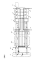
- FIG. 1 is a circuit configuration diagram of the battery monitoring device.
- the assembled battery 200 has a plurality of single cells 210 to 240.
- the cells 210 to 240 are discharged by supplying power to a load (not shown). Further, the cells 210 to 240 are charged with electric power supplied from a charging device (not shown) or the like.
- the connection harness 300 has voltage detection lines 310 to 350.
- the battery monitoring device 400 is connected to the assembled battery 200 via the connection harness 300.
- the assembled battery 200 shows an example in which the single cells 210 to 240 are connected in series. However, the assembled battery 200 may have other configurations such as a series connection of the single cells connected in parallel.
- the number of single cells is not limited.
- the battery monitoring device 400 includes a measurement filter circuit 410, an adjustment circuit 420, and a monitoring circuit 100 corresponding to the upper unit cells 210 to 220 and the lower unit cells 230 to 240, respectively.
- a microcomputer 500 is connected to the monitoring circuit 100.
- the monitoring circuit 100 is a semiconductor integrated circuit including a discharge circuit 110, a voltage measurement circuit 120, a differential amplifier 130, an AD converter 140, and a communication circuit 150, and monitors the state of a single cell.
- the voltage detection lines 310 to 350 have one end connected to the positive and negative electrodes of the cells 210 to 240, respectively, and the other end connected to the voltage measurement circuit 120 via the measurement filter circuit 410.
- the voltage of each single cell measured by the voltage measurement circuit 120 is amplified to an appropriate voltage level by the differential amplifier 130, converted to a digital value by the AD converter 140, and transmitted to the microcomputer 500 from the communication circuit 150.
- the measurement filter circuit 410 is connected to the voltage detection lines 310 to 350 and constitutes a filter circuit composed of a resistor and a measurement filter capacitor.
- the adjustment circuit 420 is a portion branched from the voltage detection lines 310 to 350 and connected to a resistor.
- the discharge circuit 110 is connected to the resistance of the adjustment circuit 420 and includes switch elements 111 to 114.
- the switch elements 111 to 114 are installed between the positive and negative electrodes of the single cells 210 to 240 and are ON / OFF controlled by the voltage measurement circuit 120. For example, when the switch element 112 is turned on for a predetermined time by the voltage measurement circuit 120, the positive electrode and the negative electrode of the single cell 220 are short-circuited via the adjustment circuit 420, and the single cell 220 is discharged. At this time, adjacent switch elements, for example, the switch element 111 are not simultaneously turned ON. *
- FIG. 2 is a circuit diagram of a main part of the battery monitoring device.
- the main circuit configuration diagram shown in FIG. 2 includes two unit cells 220 and 230 adjacent to each other, a connection harness 300 connected to the unit cells 220 and 230, filter resistors for measurement 411, 412, 413, and 414, and measurement.
- Measurement filter circuit 410 composed of filter capacitors 415, 416, and adjustment circuit 420 composed of resistors 421, 422, 423, 424.
- switch elements 112 and 113, a voltage measurement circuit 120, a differential amplifier 130, an AD converter 140, a communication circuit 150, and a microcomputer 500 are included.
- the V1 voltage is a voltage input from the upper unit cell 220 to the voltage measurement circuit 120
- the V2 voltage is a voltage input from the lower unit cell 230 adjacent to the upper unit cell 220 to the voltage measurement circuit 120. is there.
- FIG. 3A and 3B are diagrams showing changes in the V1 voltage and the V2 voltage input to the voltage measurement circuit 120.
- FIG. 3A shows a change in the V1 voltage
- FIG. 3B shows a change in the V2 voltage.
- the disconnection said by this embodiment includes that a voltage detection line becomes high resistance and will be in the state close
- the detection of the disconnection state of the voltage detection line will be described with reference to FIGS.
- the V1 voltage and the V2 voltage are the same as those in FIG.
- the voltages are the same as the voltages of the single cells 220 and 230, respectively, and there is no change.
- the voltage detection line 330 is in a disconnected state at the disconnected point B in FIG. 2
- the low potential side of V1 and the high potential side of V2 are respectively in a floating state. That is, the V1 voltage and the V2 voltage are not determined by the influence of the component characteristic variation and the consumption current variation, as indicated by reference numerals 603 and 604 in FIGS.
- the sum of the V1 voltage and the V2 voltage is always equal to the sum of the voltage of the unit cell 220 and the voltage of the unit cell 230.
- V1 + V2 single cell 220 voltage + single cell 230 voltage (1)
- the measurement filter capacitor 415 When the switch element 112 shown in FIG. 2 is turned on at time t4 for disconnection detection, the measurement filter capacitor 415 is discharged through the measurement filter resistors 411 and 412 and the adjustment resistors 421 and 422. .
- the voltage V1 is changed to 605 in FIG. 3A by the time constant calculated from the capacitance of the measurement filter capacitor 415 and the combined resistance of the resistors 411, 412, 421, and 422.
- the voltage V2 increases as indicated by 606 in FIG. 3B according to the equation (1).
- the disconnection state is detected using the difference between the V1 voltage and the V2 voltage depending on whether the voltage detection line 330 is not in the disconnection state or in the disconnection state. That is, when the value V1_d2 of the V1 voltage after the switch element 112 is turned on at time t4 falls below the low potential side fluctuation threshold, or when the value V2_d2 of the V2 voltage exceeds the high potential side fluctuation threshold, It is determined that 330 is in a disconnected state.
- the low potential side variation threshold value and the high potential side variation threshold value are obtained based on the equations (2) and (3).
- the voltage just before the high potential side in Expression (2) is the voltage V2_b2 immediately before time t4 shown in FIG. 3B, and is the voltage immediately before turning on the switch element 112.
- the voltage immediately before the low potential side in the expression (3) is the voltage V1_b2 immediately before the time t4 shown in FIG. 3A, and is a voltage immediately before the switch element 112 is turned ON.
- ⁇ is a coefficient greater than 0 and less than 1, and an optimal value is set according to the time for which the switch element 112 is turned on and the time constant of the measurement filter capacitor 415.
- High potential side fluctuation threshold High potential side immediately preceding voltage ⁇ (1 + ⁇ ) (2)
- Low potential side fluctuation threshold Low potential side immediately preceding voltage ⁇ (1- ⁇ ) (3)
- the switch element 112 is turned off at time t5, but before this time, the value V1_d2 of the V1 voltage falls below the low potential side fluctuation threshold or the value V2_d2 of the V2 voltage exceeds the high potential side fluctuation threshold, The disconnection state can be detected in a shorter time than the detection using the fixed threshold. Note that, at time t6, an example in which the switch element 112 is turned on for discharge adjustment is shown.
- the disconnection state of the voltage detection line 330 can also be detected by turning on the switch element 113.
- this case will be described with reference to FIGS.
- the switch element 112 is OFF and the switch element 113 is turned ON.
- the measurement filter capacitor 416 is discharged through the measurement filter resistors 413 and 414 and the adjustment resistors 423 and 424.
- the voltage V2 becomes 608 in FIG. 3B by the time constant calculated from the capacitance of the measurement filter capacitor 416 and the combined resistance of the resistors 413, 414, 423, and 424. Decreases as shown.
- the voltage V2 decreases, the V1 voltage increases as indicated by 607 in FIG.
- the high potential side variation threshold and the low potential side variation threshold are obtained based on Equation (2) and Equation (3).
- the voltage just before the high potential side in Expression (2) is the voltage V1_b3 immediately before time t7 shown in FIG.
- the voltage immediately before the low potential side in the equation (3) is the voltage V2_b3 immediately before time t7 shown in FIG.
- the voltage immediately before the low potential side is the value of the V2 voltage or the value of the V1 voltage corresponding to the switch element turned on.
- the voltage immediately before the low potential side is the value of the V2 voltage, and is the voltage V2_b3.
- the voltage immediately before the low potential side is the value of the V1 voltage, which is the voltage V1_b2.
- the voltage just before the high potential side is the value of the V2 voltage or the value of the V1 voltage corresponding to the switch element that is OFF.
- the switch element 113 is turned off at time t8, but before this time, the value V1_d3 of the V1 voltage exceeds the high potential side fluctuation threshold value or the value V2_d3 of the V2 voltage falls below the low potential side fluctuation threshold value.
- the disconnection state can be detected in a shorter time than the detection using the fixed threshold. Note that, at time t9, an example in which the switch element 113 is turned on for discharge adjustment is shown.
- the voltage measurement circuit 120 can measure the V1 voltage and the V2 voltage up to the input range upper limit voltage 710 shown in FIGS. 3A and 3B.
- the input range upper limit voltage 710 is determined by the combination of the AD converter 140 and the differential amplifier 130.
- the monitoring circuit 100 recognizes the input voltage as the input range upper limit voltage 710 voltage.
- the voltage V2_b3 may be lower than the actual V2 voltage, and the low potential side fluctuation threshold calculated by the equation (3) may be set inappropriately low. In this case, the voltage V2_d3 illustrated in FIG. 3B may not fall below the low potential side variation threshold.
- the high potential side variation threshold is set appropriately, and the voltage V1_d3 shown in FIG. When the value exceeds the high potential side fluctuation threshold, a disconnection state is detected.
- the coefficient ⁇ in the expressions (2) and (3) is set inappropriately large, the high potential side fluctuation threshold becomes higher than the input range upper limit voltage, and the voltage V1_d3 shown in FIG.
- the high potential fluctuation threshold cannot be exceeded. Therefore, the coefficient ⁇ is set as follows in consideration of the input range upper limit voltage 710 so that the disconnection state can be detected by at least one of the V1 voltage and the V2 voltage. That is, at least one of the formula (4) and the formula (5) is satisfied when A is in the range of 0 to 1.
- the maximum value of the battery voltage to be used is the maximum value of the voltages of the single cells 220 and 230.
- FIG. 4 is a flowchart of the battery monitoring device that detects the disconnection state of the voltage detection line.
- the detection of the disconnection state of the voltage detection line 330 will be described with reference to FIGS.
- step 801 the switch element 112 and the switch element 113 are turned off.
- step 802 the V1 voltage and the V2 voltage V1_b2 and V2_b2 in the OFF state of the switch element 112 and the switch element 113 are measured immediately before time t4 shown in FIG.
- step 803 the measured voltage V1_b2 is substituted for the voltage immediately before the low potential side in the equation (3) to calculate the low potential side fluctuation threshold. Further, the measured voltage V2_b2 is substituted for the voltage just before the high potential side in the equation (2) to calculate the high potential side variation threshold.
- step 804 the switch element 112 is turned on and the switch element 113 is turned off at time t4 shown in FIG.
- Step 805 waits for a predetermined time. This waiting time is shorter than the time required for detection using a conventional fixed threshold, and is determined by the time constant of the measurement filter capacitor 415.
- step 806 V1 voltage and V2 voltage V1_d2 and V2_d2 are measured.
- step 807 the measured voltage V1_d2 and voltage V2_d2 are compared with the low potential side variation threshold and the high potential side variation threshold calculated in step 803, respectively. If the voltage V1_d2 is smaller than the low potential side variation threshold, or if the voltage V2_d2 is larger than the high potential side variation threshold, it is determined that the circuit is disconnected, and the process proceeds to the next step 808. In step 808, the disconnection counter is incremented. The battery monitoring device 400 determines the disconnection state when the disconnection counter reaches a certain level or more.
- step 807 if the voltage V1_d2 is not smaller than the low potential side variation threshold and the voltage V2_d2 is not larger than the high potential side variation threshold, it is determined that there is no disconnection state, and step 808 is skipped.
- step 809 the switch element 112 is turned OFF at time t5 shown in FIG.
- the above processing is an example in which the switch element 112 is turned on and the disconnection state is detected. However, in the following processing, the switch element 113 is turned on and the disconnection state is detected. This example will be described below with reference to the flowchart shown in FIG.
- step 810 the switch element 112 and the switch element 113 are turned off.
- step 811 the V1 voltage and the V2 voltage V1_b3 and V2_b3 in the OFF state of the switch element 112 and the switch element 113 are measured immediately before time t7 shown in FIG.
- step 812 the measured voltage V2_b3 is substituted for the voltage immediately before the low potential side in the equation (3) to calculate the low potential side variation threshold. Further, the measured voltage V1_b3 is substituted for the voltage immediately before the high potential side in Expression (2) to calculate the high potential side variation threshold.
- step 813 the switch element 112 is turned off and the switch element 113 is turned on at time t7 shown in FIG.
- Step 814 waits for a predetermined time. This waiting time is shorter than the time required for detection using the conventional fixed threshold.
- step 815 the V1 voltage and the V2 voltage V1_d3 and V2_d3 are measured.
- step 816 the measured voltage V1_d3 and voltage V2_d3 are respectively compared with the low potential side variation threshold and the high potential side variation threshold calculated in step 812. If the voltage V1_d3 is larger than the high potential side variation threshold, or if the voltage V2_d3 is smaller than the low potential side variation threshold, it is determined that the circuit is disconnected and the process proceeds to the next step 817.
- step 817 the disconnection counter is incremented. The battery monitoring device determines the disconnection state when the disconnection counter reaches a certain level or more.
- step 816 If it is determined in step 816 that the voltage V1_d3 is not smaller than the low potential side variation threshold and the voltage V2_d3 is not larger than the high potential variation threshold, it is determined that there is no disconnection and step 817 is skipped.
- step 818 the switch element 113 is turned OFF at time t8 shown in FIG.
- the disconnection state of the voltage detection line 330 can be detected by the processing described above.
- the disconnection state may be detected by turning on the switch element 113, or the disconnection state may be detected by turning on the switch element 112.
- the switch element 112 may be turned on to detect a disconnection state, and then the switch element 113 may be turned on to detect the disconnection state. In this case, the disconnection state can be reliably detected.
- the detection of the disconnection state of the voltage detection line 330 has been described. However, the detection of the disconnection state of the voltage detection lines 320 and 340 can be performed in the same manner.
- the disconnection state of the voltage detection lines 310 and 350 can be detected by turning on the switch element 111 or 114.
- a monitoring circuit 100 that is provided corresponding to the assembled battery 200 including a plurality of unit cells 210, 220, 230, and 240 and that monitors the state of the unit cells 210, 220, 230, and 240; 220, 230, 240, voltage detection lines 310, 320, 330, 340, 350 that connect the cells 210, 220, 230, 240 and the monitoring circuit 100, and voltage detection lines 310, 320, 330, 340, 350, and a battery monitoring device 400 that includes switch elements 111, 112, 113, 114 that adjust the voltage of the single cells 210, 220, 230, 240.
- Fluctuation threshold value determined based on the voltage immediately before diagnosing the disconnection state of the battery voltage of the adjacent single cells 210, 220, 230, 240 Comparison detects the disconnection state of the voltage detecting lines 310,320,330,340,350 on the basis of the comparison result. As a result, even when the battery voltage is high, the ON control time of the switch element is shortened, and the disconnection state can be reliably detected.
- the battery monitoring apparatus 400 further includes measurement filter capacitors 415 and 416 connected between the voltage detection lines 310, 320, 330, 340, and 350, and the switch elements 111, 112, 113, and 114 are in a conductive state.
- the battery voltage associated with charging / discharging of the measurement filter capacitors 415 and 416 is compared with the fluctuation threshold value. Thereby, the ON control time of the switch element is shortened, and the disconnection state can be reliably detected.
- the fluctuation threshold value has a high potential side fluctuation threshold value and a low potential side fluctuation threshold value
- the high potential side fluctuation threshold value is a voltage on the high potential side immediately before diagnosing the disconnection state.
- the low-potential-side variation threshold is a low-potential voltage that is a voltage on the low-potential side immediately before diagnosing a disconnection state It is determined based on the following equation (2) based on the immediately preceding voltage and the coefficient ⁇ .
- High potential side fluctuation threshold high potential side immediately preceding voltage ⁇ (1 + ⁇ ) (1)
- Low potential side fluctuation threshold Low potential side immediately preceding voltage ⁇ (1 ⁇ ) (2)
- the coefficient ⁇ is expressed by the following formula (3) or formula (3) or the formula (3) or the formula ( It is a value satisfying at least one of 4).
- the high potential side variation threshold and the low potential side variation threshold can be appropriately set.
- the present invention is not limited to the above-described embodiment, and other forms conceivable within the scope of the technical idea of the present invention are also included in the scope of the present invention as long as the characteristics of the present invention are not impaired. .
- DESCRIPTION OF SYMBOLS 100 Monitoring circuit 110 Discharge circuit 111 Switch element 112 Switch element 113 Switch element 114 Switch element 120 Voltage measurement circuit 130 Differential amplifier 140 AD converter 150 Communication circuit 200 Battery pack 210 Cell 220 Battery 210 Cell 240 Cell 300 Connection Harness 310 Voltage detection line 320 Voltage detection line 330 Voltage detection line 340 Voltage detection line 350 Voltage detection line 400 Battery monitoring device 410 Measurement filter circuit 411 Measurement filter resistance 412 Measurement filter resistance 413 Measurement filter resistance 414 Measurement filter resistance 415 Filter capacitor for measurement 416 Filter capacitor for measurement 420 Adjustment circuit 421 Adjustment resistor 422 Adjustment resistor 423 Adjustment resistor 424 Adjustment resistor 500 Microcomputer
Landscapes
- Physics & Mathematics (AREA)
- General Physics & Mathematics (AREA)
- Engineering & Computer Science (AREA)
- Power Engineering (AREA)
- Manufacturing & Machinery (AREA)
- Chemical & Material Sciences (AREA)
- Chemical Kinetics & Catalysis (AREA)
- Electrochemistry (AREA)
- General Chemical & Material Sciences (AREA)
- Testing Of Short-Circuits, Discontinuities, Leakage, Or Incorrect Line Connections (AREA)
- Secondary Cells (AREA)
- Charge And Discharge Circuits For Batteries Or The Like (AREA)
Abstract
Lorsque la tension de batterie d'une batterie unitaire est une tension élevée, un certain temps s'est écoulé jusqu'à ce que la tension détectée diminue jusqu'à une valeur seuil fixe, ce qui allonge le temps de commande MARCHE d'un élément de commutation afin de détecter de manière fiable une rupture de fil. La présente invention concerne un dispositif de surveillance de batterie comprenant : un circuit de surveillance disposé en correspondance avec un ensemble batterie composé d'une pluralité de batteries unitaires et surveillant les états des batteries unitaires; des lignes de détection de tension disposées en correspondance avec les batteries unitaires connectant les batteries unitaires et le circuit de surveillance; et des éléments de commutation disposés entre les lignes de détection de tension et réglant les tensions des batteries unitaires, le dispositif de surveillance de batterie comparant les tensions de batterie de batteries unitaires voisines avec une valeur seuil fluctuante déterminée en fonction d'une tension juste avant qu'un état de rupture de fil soit diagnostiqué et détectant l'état de rupture de fil d'une ligne de détection de tension en fonction d'un résultat de la comparaison.
Priority Applications (2)
| Application Number | Priority Date | Filing Date | Title |
|---|---|---|---|
| JP2019525195A JP6853884B2 (ja) | 2017-06-14 | 2018-05-08 | 電池監視装置 |
| US16/619,397 US11249139B2 (en) | 2017-06-14 | 2018-05-08 | Battery monitoring system |
Applications Claiming Priority (2)
| Application Number | Priority Date | Filing Date | Title |
|---|---|---|---|
| JP2017-117182 | 2017-06-14 | ||
| JP2017117182 | 2017-06-14 |
Publications (1)
| Publication Number | Publication Date |
|---|---|
| WO2018230187A1 true WO2018230187A1 (fr) | 2018-12-20 |
Family
ID=64661000
Family Applications (1)
| Application Number | Title | Priority Date | Filing Date |
|---|---|---|---|
| PCT/JP2018/017697 Ceased WO2018230187A1 (fr) | 2017-06-14 | 2018-05-08 | Dispositif de surveillance de batterie |
Country Status (3)
| Country | Link |
|---|---|
| US (1) | US11249139B2 (fr) |
| JP (1) | JP6853884B2 (fr) |
| WO (1) | WO2018230187A1 (fr) |
Cited By (2)
| Publication number | Priority date | Publication date | Assignee | Title |
|---|---|---|---|---|
| CN110441697A (zh) * | 2019-08-30 | 2019-11-12 | 浙江八达电子仪表有限公司 | 一种快速检测电能表锂电池电量的装置 |
| JP2021009032A (ja) * | 2019-06-28 | 2021-01-28 | 株式会社デンソーテン | 断線検知装置および断線検知方法 |
Families Citing this family (4)
| Publication number | Priority date | Publication date | Assignee | Title |
|---|---|---|---|---|
| CA3067183A1 (fr) * | 2017-06-16 | 2018-12-20 | Koki Holdings Co., Ltd. | Bloc-batterie et appareil electrique utilisant le bloc-batterie |
| DE102020117744A1 (de) * | 2020-07-06 | 2022-01-13 | HELLA GmbH & Co. KGaA | Verfahren und Vorrichtung zur Überwachen eines Tiefpassfilters sowie Batteriemanagementsystem, Batterie sowie Fahrzeug |
| CN113311342A (zh) * | 2021-05-28 | 2021-08-27 | 中国电力科学研究院有限公司 | 一种锂离子电池热失控监测系统及方法 |
| CN119270140B (zh) * | 2024-09-11 | 2025-10-24 | 武汉小鹏智能制造有限公司 | 电池包电流采样断线诊断方法、存储介质及电子装置 |
Citations (4)
| Publication number | Priority date | Publication date | Assignee | Title |
|---|---|---|---|---|
| JP2010256155A (ja) * | 2009-04-24 | 2010-11-11 | Yazaki Corp | 断線検出装置 |
| JP2012122856A (ja) * | 2010-12-08 | 2012-06-28 | Toshiba Corp | 組電池装置 |
| JP2014102127A (ja) * | 2012-11-19 | 2014-06-05 | Denso Corp | 電池監視装置 |
| JP2016152720A (ja) * | 2015-02-18 | 2016-08-22 | 三菱電機株式会社 | セルバランス回路及びその故障診断装置 |
Family Cites Families (11)
| Publication number | Priority date | Publication date | Assignee | Title |
|---|---|---|---|---|
| JP3956932B2 (ja) * | 2003-11-07 | 2007-08-08 | ソニー株式会社 | 充電器および充電状態判定方法 |
| KR100812760B1 (ko) * | 2005-12-08 | 2008-03-12 | 김득수 | 축전지 내부 임피던스 유효성분 측정연산 장치 및 그 방법 |
| JP5469813B2 (ja) * | 2008-01-29 | 2014-04-16 | 株式会社日立製作所 | 車両用電池システム |
| JP5486780B2 (ja) * | 2008-07-01 | 2014-05-07 | 株式会社日立製作所 | 電池システム |
| US8629687B2 (en) | 2009-04-24 | 2014-01-14 | Yazaki Corporation | Disconnection detecting device |
| US9411004B2 (en) * | 2014-05-28 | 2016-08-09 | Ford Global Technologies, Llc | Continuous leakage detection circuit with integrated robustness check and balanced fault detection |
| WO2016051684A1 (fr) * | 2014-09-29 | 2016-04-07 | パナソニックIpマネジメント株式会社 | Dispositif de commande de pile rechargeable et système de gestion de module de stockage |
| DE102015117171B4 (de) * | 2014-10-09 | 2019-03-21 | Denso Corporation | Batteriezustandsabschätzvorrichtung |
| JP6402597B2 (ja) | 2014-11-12 | 2018-10-10 | 株式会社Gsユアサ | 組電池の監視装置、蓄電装置、断線診断方法 |
| JP2018038097A (ja) * | 2015-01-16 | 2018-03-08 | パナソニックIpマネジメント株式会社 | 蓄電池制御システム |
| WO2017133400A2 (fr) * | 2016-02-05 | 2017-08-10 | 广东欧珀移动通信有限公司 | Adaptateur et procédé de commande de charge |
-
2018
- 2018-05-08 WO PCT/JP2018/017697 patent/WO2018230187A1/fr not_active Ceased
- 2018-05-08 JP JP2019525195A patent/JP6853884B2/ja active Active
- 2018-05-08 US US16/619,397 patent/US11249139B2/en active Active
Patent Citations (4)
| Publication number | Priority date | Publication date | Assignee | Title |
|---|---|---|---|---|
| JP2010256155A (ja) * | 2009-04-24 | 2010-11-11 | Yazaki Corp | 断線検出装置 |
| JP2012122856A (ja) * | 2010-12-08 | 2012-06-28 | Toshiba Corp | 組電池装置 |
| JP2014102127A (ja) * | 2012-11-19 | 2014-06-05 | Denso Corp | 電池監視装置 |
| JP2016152720A (ja) * | 2015-02-18 | 2016-08-22 | 三菱電機株式会社 | セルバランス回路及びその故障診断装置 |
Cited By (5)
| Publication number | Priority date | Publication date | Assignee | Title |
|---|---|---|---|---|
| JP2021009032A (ja) * | 2019-06-28 | 2021-01-28 | 株式会社デンソーテン | 断線検知装置および断線検知方法 |
| EP3839538A4 (fr) * | 2019-06-28 | 2022-06-22 | Denso Ten Limited | Dispositif de détection de déconnexion et procédé de détection de déconnexion |
| JP7240972B2 (ja) | 2019-06-28 | 2023-03-16 | 株式会社デンソーテン | 断線検知装置および断線検知方法 |
| US11909233B2 (en) | 2019-06-28 | 2024-02-20 | Denso Ten Limited | Disconnection detection device and disconnection detection method |
| CN110441697A (zh) * | 2019-08-30 | 2019-11-12 | 浙江八达电子仪表有限公司 | 一种快速检测电能表锂电池电量的装置 |
Also Published As
| Publication number | Publication date |
|---|---|
| JP6853884B2 (ja) | 2021-03-31 |
| JPWO2018230187A1 (ja) | 2020-03-19 |
| US20200124677A1 (en) | 2020-04-23 |
| US11249139B2 (en) | 2022-02-15 |
Similar Documents
| Publication | Publication Date | Title |
|---|---|---|
| JP6853884B2 (ja) | 電池監視装置 | |
| US8489347B2 (en) | Battery pack monitoring apparatus | |
| US8841915B2 (en) | Battery voltage monitoring apparatus | |
| US9128161B2 (en) | Voltage monitoring device | |
| EP2418751B1 (fr) | Chargeur de batterie et procédé de charge de batterie | |
| JP5928509B2 (ja) | 電池監視装置 | |
| JP5326973B2 (ja) | 電池監視装置 | |
| US20120194135A1 (en) | Battery voltage monitoring apparatus | |
| JP5974849B2 (ja) | 電池監視装置 | |
| US9863993B2 (en) | Storage battery monitoring device with wiring disconnection detection | |
| JP6016754B2 (ja) | 組電池電圧検出装置 | |
| WO2014045567A1 (fr) | Dispositif de source de puissance, et véhicule électrique et dispositif d'accumulation de puissance fournis avec ledit dispositif de source de puissance | |
| US20150048795A1 (en) | Charge control apparatus and charge control method | |
| JP2012016174A (ja) | 車両用の電源装置 | |
| US11824392B2 (en) | Battery pack | |
| US11909233B2 (en) | Disconnection detection device and disconnection detection method | |
| US9466993B2 (en) | Charge and discharge control circuit having an intermediate terminal disconnection detecting circuit for detecting disconnection with secondary batteries | |
| US10627453B2 (en) | Integrated circuit with built-in status monitoring unit and power supply device provided with said integrated circuit | |
| JP6236775B2 (ja) | 検知装置 | |
| JP6787705B2 (ja) | 異常検出装置、および組電池システム | |
| JP6598209B2 (ja) | 電圧検出装置 | |
| JP4693761B2 (ja) | 組電池システム | |
| JP2012084443A (ja) | 電源装置 | |
| JP2013179751A (ja) | 組電池の制御装置 | |
| US20260011999A1 (en) | Vehicle cutoff device |
Legal Events
| Date | Code | Title | Description |
|---|---|---|---|
| 121 | Ep: the epo has been informed by wipo that ep was designated in this application |
Ref document number: 18816495 Country of ref document: EP Kind code of ref document: A1 |
|
| ENP | Entry into the national phase |
Ref document number: 2019525195 Country of ref document: JP Kind code of ref document: A |
|
| NENP | Non-entry into the national phase |
Ref country code: DE |
|
| 122 | Ep: pct application non-entry in european phase |
Ref document number: 18816495 Country of ref document: EP Kind code of ref document: A1 |