WO2018230281A1 - 空調システム、空調方法、及び制御装置 - Google Patents
空調システム、空調方法、及び制御装置 Download PDFInfo
- Publication number
- WO2018230281A1 WO2018230281A1 PCT/JP2018/019740 JP2018019740W WO2018230281A1 WO 2018230281 A1 WO2018230281 A1 WO 2018230281A1 JP 2018019740 W JP2018019740 W JP 2018019740W WO 2018230281 A1 WO2018230281 A1 WO 2018230281A1
- Authority
- WO
- WIPO (PCT)
- Prior art keywords
- air
- heat exchanger
- air conditioning
- refrigerant
- expansion valve
- Prior art date
- Legal status (The legal status is an assumption and is not a legal conclusion. Google has not performed a legal analysis and makes no representation as to the accuracy of the status listed.)
- Ceased
Links
Images

Classifications
-
- F—MECHANICAL ENGINEERING; LIGHTING; HEATING; WEAPONS; BLASTING
- F24—HEATING; RANGES; VENTILATING
- F24F—AIR-CONDITIONING; AIR-HUMIDIFICATION; VENTILATION; USE OF AIR CURRENTS FOR SCREENING
- F24F11/00—Control or safety arrangements
- F24F11/70—Control systems characterised by their outputs; Constructional details thereof
- F24F11/72—Control systems characterised by their outputs; Constructional details thereof for controlling the supply of treated air, e.g. its pressure
- F24F11/74—Control systems characterised by their outputs; Constructional details thereof for controlling the supply of treated air, e.g. its pressure for controlling air flow rate or air velocity
- F24F11/77—Control systems characterised by their outputs; Constructional details thereof for controlling the supply of treated air, e.g. its pressure for controlling air flow rate or air velocity by controlling the speed of ventilators
-
- F—MECHANICAL ENGINEERING; LIGHTING; HEATING; WEAPONS; BLASTING
- F24—HEATING; RANGES; VENTILATING
- F24F—AIR-CONDITIONING; AIR-HUMIDIFICATION; VENTILATION; USE OF AIR CURRENTS FOR SCREENING
- F24F11/00—Control or safety arrangements
- F24F11/30—Control or safety arrangements for purposes related to the operation of the system, e.g. for safety or monitoring
- F24F11/32—Responding to malfunctions or emergencies
- F24F11/36—Responding to malfunctions or emergencies to leakage of heat-exchange fluid
-
- F—MECHANICAL ENGINEERING; LIGHTING; HEATING; WEAPONS; BLASTING
- F24—HEATING; RANGES; VENTILATING
- F24F—AIR-CONDITIONING; AIR-HUMIDIFICATION; VENTILATION; USE OF AIR CURRENTS FOR SCREENING
- F24F11/00—Control or safety arrangements
- F24F11/50—Control or safety arrangements characterised by user interfaces or communication
- F24F11/52—Indication arrangements, e.g. displays
-
- F—MECHANICAL ENGINEERING; LIGHTING; HEATING; WEAPONS; BLASTING
- F24—HEATING; RANGES; VENTILATING
- F24F—AIR-CONDITIONING; AIR-HUMIDIFICATION; VENTILATION; USE OF AIR CURRENTS FOR SCREENING
- F24F11/00—Control or safety arrangements
- F24F11/62—Control or safety arrangements characterised by the type of control or by internal processing, e.g. using fuzzy logic, adaptive control or estimation of values
- F24F11/63—Electronic processing
- F24F11/64—Electronic processing using pre-stored data
-
- F—MECHANICAL ENGINEERING; LIGHTING; HEATING; WEAPONS; BLASTING
- F24—HEATING; RANGES; VENTILATING
- F24F—AIR-CONDITIONING; AIR-HUMIDIFICATION; VENTILATION; USE OF AIR CURRENTS FOR SCREENING
- F24F11/00—Control or safety arrangements
- F24F11/70—Control systems characterised by their outputs; Constructional details thereof
- F24F11/72—Control systems characterised by their outputs; Constructional details thereof for controlling the supply of treated air, e.g. its pressure
- F24F11/74—Control systems characterised by their outputs; Constructional details thereof for controlling the supply of treated air, e.g. its pressure for controlling air flow rate or air velocity
-
- F—MECHANICAL ENGINEERING; LIGHTING; HEATING; WEAPONS; BLASTING
- F24—HEATING; RANGES; VENTILATING
- F24F—AIR-CONDITIONING; AIR-HUMIDIFICATION; VENTILATION; USE OF AIR CURRENTS FOR SCREENING
- F24F11/00—Control or safety arrangements
- F24F11/70—Control systems characterised by their outputs; Constructional details thereof
- F24F11/80—Control systems characterised by their outputs; Constructional details thereof for controlling the temperature of the supplied air
- F24F11/83—Control systems characterised by their outputs; Constructional details thereof for controlling the temperature of the supplied air by controlling the supply of heat-exchange fluids to heat-exchangers
- F24F11/84—Control systems characterised by their outputs; Constructional details thereof for controlling the temperature of the supplied air by controlling the supply of heat-exchange fluids to heat-exchangers using valves
-
- F—MECHANICAL ENGINEERING; LIGHTING; HEATING; WEAPONS; BLASTING
- F24—HEATING; RANGES; VENTILATING
- F24F—AIR-CONDITIONING; AIR-HUMIDIFICATION; VENTILATION; USE OF AIR CURRENTS FOR SCREENING
- F24F11/00—Control or safety arrangements
- F24F11/70—Control systems characterised by their outputs; Constructional details thereof
- F24F11/80—Control systems characterised by their outputs; Constructional details thereof for controlling the temperature of the supplied air
- F24F11/86—Control systems characterised by their outputs; Constructional details thereof for controlling the temperature of the supplied air by controlling compressors within refrigeration or heat pump circuits
-
- F—MECHANICAL ENGINEERING; LIGHTING; HEATING; WEAPONS; BLASTING
- F24—HEATING; RANGES; VENTILATING
- F24F—AIR-CONDITIONING; AIR-HUMIDIFICATION; VENTILATION; USE OF AIR CURRENTS FOR SCREENING
- F24F3/00—Air-conditioning systems in which conditioned primary air is supplied from one or more central stations to distributing units in the rooms or spaces where it may receive secondary treatment; Apparatus specially designed for such systems
- F24F3/044—Systems in which all treatment is given in the central station, i.e. all-air systems
-
- F—MECHANICAL ENGINEERING; LIGHTING; HEATING; WEAPONS; BLASTING
- F25—REFRIGERATION OR COOLING; COMBINED HEATING AND REFRIGERATION SYSTEMS; HEAT PUMP SYSTEMS; MANUFACTURE OR STORAGE OF ICE; LIQUEFACTION SOLIDIFICATION OF GASES
- F25B—REFRIGERATION MACHINES, PLANTS OR SYSTEMS; COMBINED HEATING AND REFRIGERATION SYSTEMS; HEAT PUMP SYSTEMS
- F25B13/00—Compression machines, plants or systems, with reversible cycle
-
- F—MECHANICAL ENGINEERING; LIGHTING; HEATING; WEAPONS; BLASTING
- F25—REFRIGERATION OR COOLING; COMBINED HEATING AND REFRIGERATION SYSTEMS; HEAT PUMP SYSTEMS; MANUFACTURE OR STORAGE OF ICE; LIQUEFACTION SOLIDIFICATION OF GASES
- F25B—REFRIGERATION MACHINES, PLANTS OR SYSTEMS; COMBINED HEATING AND REFRIGERATION SYSTEMS; HEAT PUMP SYSTEMS
- F25B40/00—Subcoolers, desuperheaters or superheaters
- F25B40/02—Subcoolers
-
- F—MECHANICAL ENGINEERING; LIGHTING; HEATING; WEAPONS; BLASTING
- F25—REFRIGERATION OR COOLING; COMBINED HEATING AND REFRIGERATION SYSTEMS; HEAT PUMP SYSTEMS; MANUFACTURE OR STORAGE OF ICE; LIQUEFACTION SOLIDIFICATION OF GASES
- F25B—REFRIGERATION MACHINES, PLANTS OR SYSTEMS; COMBINED HEATING AND REFRIGERATION SYSTEMS; HEAT PUMP SYSTEMS
- F25B49/00—Arrangement or mounting of control or safety devices
- F25B49/02—Arrangement or mounting of control or safety devices for compression type machines, plants or systems
-
- F—MECHANICAL ENGINEERING; LIGHTING; HEATING; WEAPONS; BLASTING
- F24—HEATING; RANGES; VENTILATING
- F24F—AIR-CONDITIONING; AIR-HUMIDIFICATION; VENTILATION; USE OF AIR CURRENTS FOR SCREENING
- F24F2140/00—Control inputs relating to system states
- F24F2140/20—Heat-exchange fluid temperature
-
- F—MECHANICAL ENGINEERING; LIGHTING; HEATING; WEAPONS; BLASTING
- F25—REFRIGERATION OR COOLING; COMBINED HEATING AND REFRIGERATION SYSTEMS; HEAT PUMP SYSTEMS; MANUFACTURE OR STORAGE OF ICE; LIQUEFACTION SOLIDIFICATION OF GASES
- F25B—REFRIGERATION MACHINES, PLANTS OR SYSTEMS; COMBINED HEATING AND REFRIGERATION SYSTEMS; HEAT PUMP SYSTEMS
- F25B2313/00—Compression machines, plants or systems with reversible cycle not otherwise provided for
- F25B2313/029—Control issues
- F25B2313/0293—Control issues related to the indoor fan, e.g. controlling speed
-
- F—MECHANICAL ENGINEERING; LIGHTING; HEATING; WEAPONS; BLASTING
- F25—REFRIGERATION OR COOLING; COMBINED HEATING AND REFRIGERATION SYSTEMS; HEAT PUMP SYSTEMS; MANUFACTURE OR STORAGE OF ICE; LIQUEFACTION SOLIDIFICATION OF GASES
- F25B—REFRIGERATION MACHINES, PLANTS OR SYSTEMS; COMBINED HEATING AND REFRIGERATION SYSTEMS; HEAT PUMP SYSTEMS
- F25B2313/00—Compression machines, plants or systems with reversible cycle not otherwise provided for
- F25B2313/031—Sensor arrangements
- F25B2313/0314—Temperature sensors near the indoor heat exchanger
-
- F—MECHANICAL ENGINEERING; LIGHTING; HEATING; WEAPONS; BLASTING
- F25—REFRIGERATION OR COOLING; COMBINED HEATING AND REFRIGERATION SYSTEMS; HEAT PUMP SYSTEMS; MANUFACTURE OR STORAGE OF ICE; LIQUEFACTION SOLIDIFICATION OF GASES
- F25B—REFRIGERATION MACHINES, PLANTS OR SYSTEMS; COMBINED HEATING AND REFRIGERATION SYSTEMS; HEAT PUMP SYSTEMS
- F25B2400/00—Component parts or details not otherwise provided for in this subclass
- F25B2400/04—Refrigeration circuit bypassing means
- F25B2400/0401—Refrigeration circuit bypassing means for compressors
-
- F—MECHANICAL ENGINEERING; LIGHTING; HEATING; WEAPONS; BLASTING
- F25—REFRIGERATION OR COOLING; COMBINED HEATING AND REFRIGERATION SYSTEMS; HEAT PUMP SYSTEMS; MANUFACTURE OR STORAGE OF ICE; LIQUEFACTION SOLIDIFICATION OF GASES
- F25B—REFRIGERATION MACHINES, PLANTS OR SYSTEMS; COMBINED HEATING AND REFRIGERATION SYSTEMS; HEAT PUMP SYSTEMS
- F25B2400/00—Component parts or details not otherwise provided for in this subclass
- F25B2400/13—Economisers
-
- F—MECHANICAL ENGINEERING; LIGHTING; HEATING; WEAPONS; BLASTING
- F25—REFRIGERATION OR COOLING; COMBINED HEATING AND REFRIGERATION SYSTEMS; HEAT PUMP SYSTEMS; MANUFACTURE OR STORAGE OF ICE; LIQUEFACTION SOLIDIFICATION OF GASES
- F25B—REFRIGERATION MACHINES, PLANTS OR SYSTEMS; COMBINED HEATING AND REFRIGERATION SYSTEMS; HEAT PUMP SYSTEMS
- F25B2500/00—Problems to be solved
- F25B2500/22—Preventing, detecting or repairing leaks of refrigeration fluids
- F25B2500/222—Detecting refrigerant leaks
-
- F—MECHANICAL ENGINEERING; LIGHTING; HEATING; WEAPONS; BLASTING
- F25—REFRIGERATION OR COOLING; COMBINED HEATING AND REFRIGERATION SYSTEMS; HEAT PUMP SYSTEMS; MANUFACTURE OR STORAGE OF ICE; LIQUEFACTION SOLIDIFICATION OF GASES
- F25B—REFRIGERATION MACHINES, PLANTS OR SYSTEMS; COMBINED HEATING AND REFRIGERATION SYSTEMS; HEAT PUMP SYSTEMS
- F25B2600/00—Control issues
- F25B2600/25—Control of valves
- F25B2600/2513—Expansion valves
-
- Y—GENERAL TAGGING OF NEW TECHNOLOGICAL DEVELOPMENTS; GENERAL TAGGING OF CROSS-SECTIONAL TECHNOLOGIES SPANNING OVER SEVERAL SECTIONS OF THE IPC; TECHNICAL SUBJECTS COVERED BY FORMER USPC CROSS-REFERENCE ART COLLECTIONS [XRACs] AND DIGESTS
- Y02—TECHNOLOGIES OR APPLICATIONS FOR MITIGATION OR ADAPTATION AGAINST CLIMATE CHANGE
- Y02B—CLIMATE CHANGE MITIGATION TECHNOLOGIES RELATED TO BUILDINGS, e.g. HOUSING, HOUSE APPLIANCES OR RELATED END-USER APPLICATIONS
- Y02B30/00—Energy efficient heating, ventilation or air conditioning [HVAC]
- Y02B30/70—Efficient control or regulation technologies, e.g. for control of refrigerant flow, motor or heating
Definitions
- the present invention relates to an air conditioning system, an air conditioning method, and a control device.
- Patent Document 1 discloses an air conditioning system including “a number control unit that controls the number of operating compressors and the operating frequency of each compressor to be operated so as to satisfy the capacity requirement according to the air conditioning load”. Is described.
- Patent Document 1 describes the control of the compressor as described above, but does not describe the control of the equipment included in the air handling unit.
- an air handling unit to be connected to an outdoor unit its specifications are often limited in consideration of the reliability of the refrigeration cycle.
- the specifications of the air handling unit have been limited so as to have a heat exchange performance equivalent to that of a general indoor unit.
- an air handling unit having a large-capacity heat exchanger is selected, and the others are excluded from the selection.
- the degree of freedom in selection is reduced (that is, there are fewer options for an air handling unit that can be combined with an outdoor unit).
- an object of the present invention is to provide an air conditioning system having a high degree of freedom when selecting an air handling unit.
- the present invention provides an outdoor unit having at least a compressor and a first heat exchanger, an air handling unit having an air supply fan and a second heat exchanger, an expansion valve, and a control unit.
- the rotational speed of the air supply fan and / or the opening of the expansion valve is adjusted based on information including a detection value.
- FIG. 1 is a configuration diagram of an air conditioning system 100 according to the first embodiment. 1 indicates the direction in which the refrigerant flows during the cooling operation, and the broken line arrow in FIG. 1 indicates the direction in which the refrigerant flows during the heating operation. Moreover, the white arrow described in the vicinity of the air handling unit 30 (Air Handling Unit: described as “AHU” in FIG. 1) in FIG. 1 indicates the direction in which air flows.
- Air Handling Unit: described as “AHU” in FIG. 1 indicates the direction in which air flows.
- the air conditioning system 100 is a system that performs air conditioning by circulating a refrigerant in a refrigeration cycle (heat pump cycle). As shown in FIG. 1, the air conditioning system 100 includes an outdoor unit 10, an air handling unit 30, and a decompression device 40. In addition to the configuration described above, the air conditioning system 100 includes refrigerant temperature sensors 51 and 52, air temperature sensors 53 and 54, a control unit 60 (control unit), and a remote controller 70 (display unit). Yes.
- the outdoor unit 10 includes a compressor 11, an accumulator 12, an outdoor heat exchanger 13 (first heat exchanger), an outdoor fan 14, a four-way valve 15, and an outdoor expansion valve 16.
- the outdoor unit 10 has an oil separator 17, capillary tubes 18 and 22, a check valve 19, a two-way valve 21, a supercooler 23, and a supercooling expansion valve 24 in addition to the above-described configuration. And an outdoor control circuit 25.
- the compressor 11 is a device that compresses a low-temperature and low-pressure gas refrigerant and discharges it as a high-temperature and high-pressure gas refrigerant.
- the accumulator 12 is a shell-like member for gas-liquid separation of the refrigerant, and is provided on the suction side of the compressor 11.
- the outdoor heat exchanger 13 is a heat exchanger in which heat exchange is performed between the refrigerant flowing through the heat transfer tube (not shown) and the outside air sent from the outdoor fan 14.
- the outdoor fan 14 is a fan that sends outside air to the outdoor heat exchanger 13, and is installed in the vicinity of the outdoor heat exchanger 13.
- the four-way valve 15 is a valve that switches the flow direction of the refrigerant according to the operation mode of the air conditioning system 100. That is, during the cooling operation (see the solid line arrow), the discharge side of the compressor 11 is connected to one end m of the outdoor heat exchanger 13 via the four-way valve 15 or the like, and the suction side of the compressor 11 is connected to the four-way valve 15. And one end n of the heat exchanger 32 (second heat exchanger) via a pipe k1 and the like. Thereby, the outdoor heat exchanger 13 functions as a condenser, and the heat exchanger 32 functions as an evaporator.
- the above-described pipe k1 is a pipe through which the gas refrigerant flows.
- the four-way valve 15 and one end n of the heat exchanger 32 are connected via the pipe k1.
- the discharge side of the compressor 11 is connected to one end n of the heat exchanger 32 via the four-way valve 15, the pipe k ⁇ b> 1, and the like, and the suction side of the compressor 11 is It is connected to one end m of the outdoor heat exchanger 13 through a valve 15 or the like.
- the heat exchanger 32 functions as a condenser
- the outdoor heat exchanger 13 functions as an evaporator.
- the outdoor expansion valve 16 is a valve that depressurizes the refrigerant flowing into itself, and is installed near the other end v of the outdoor heat exchanger 13 in the pipe k2.
- the pipe k2 is a pipe through which a liquid refrigerant or a gas-liquid two-phase refrigerant flows.
- the other end v of the outdoor heat exchanger 13 and the other end w of the heat exchanger 32 are connected via the pipe k2.
- a part of the pipe k2 (between the outdoor expansion valve 16 and the supercooler 23) is configured as a heat transfer pipe ka, and the heat transfer pipe ka passes through the fins of the outdoor heat exchanger 13. Yes.
- the oil separator 17 separates lubricating oil mixed in the refrigerant discharged from the compressor 11, and is installed on the discharge side of the compressor 11.
- the lubricating oil separated by the oil separator 17 is guided to the accumulator 12 through the pipe k3.
- the refrigerant from which the lubricating oil is separated by the oil separator 17 is guided to the four-way valve 15 via a check valve 19 and the like which will be described later.
- the capillary tube 18 is a metal tube having a relatively small diameter, and is installed in the pipe k3.
- the check valve 19 is a valve that allows the flow of refrigerant toward the four-way valve 15 via the oil separator 17 and prohibits the reverse flow, and is installed on the downstream side of the oil separator 17.
- the two-way valve 21 and the capillary tube 22 are members for returning the lubricating oil mixed in the refrigerant to the accumulator 12, and are installed in the pipe k5.
- the upstream end of the pipe k5 is connected to the downstream side of the check valve 19, and the downstream end branched into three is connected to the pipe k6 (pipe connecting the four-way valve 15 and the accumulator 12). It is connected.
- the subcooler 23 cools the refrigerant condensed in the outdoor heat exchanger 13 or the heat exchanger 32, and is installed between the outdoor expansion valve 16 and an expansion valve 41 described later in the pipe k2. .
- the supercooler 23 includes a subcooling main flow pipe 23a constituting a part of the pipe k2, and a subcooling subflow having a double pipe structure together with the supercooling main flow pipe 23a.
- the subcooling subflow pipe 23b has one end connected to a pipe k2 (between the supercooler 23 and the outdoor expansion valve 16) via a pipe k7, and the other end connected to the pipe. It is connected to the piping k6 (upstream side of the accumulator 12) via k8.
- the supercooling expansion valve 24 is a valve that depressurizes the refrigerant flowing into the subcooling expansion valve 24, and is installed in the pipe k7.
- the outdoor control circuit 25 includes electronic circuits such as a CPU (Central Processing Unit), a ROM (Read Only Memory), a RAM (Random Access Memory), and various interfaces. Then, the program stored in the ROM is read out and expanded in the RAM, and the CPU executes various processes.
- a CPU Central Processing Unit
- ROM Read Only Memory
- RAM Random Access Memory
- the outdoor control circuit 25 includes a receiving unit 25a, a calculation unit 25b, and a communication unit 25c.
- the receiving unit 25a receives detection values of sensors (not shown) installed in the outdoor unit 10 (outdoor temperature sensors, sensors that detect the suction temperature, discharge temperature, discharge pressure, and the like of the compressor 11).
- the computing unit 25b is configured to use the compressor 11, the outdoor fan 14, the four-way valve 15, the outdoor expansion valve 16, and the supercooling expansion valve based on the detection values received by the receiving unit 25a, data acquired from the control unit 60, and the like.
- a control command value such as 24 is calculated.
- the communication unit 25c has a function of performing predetermined communication with the control unit 60 described later.
- the air handling unit 30 is a device that takes in air through the opening h1 of the housing 31 and supplies the air subjected to heat exchange by the heat exchanger 32 to the air-conditioned space through another opening h2. As shown in FIG. 1, the air handling unit 30 includes a housing 31, a heat exchanger 32, and an air supply fan 33.
- the casing 31 is a box-like member in which the heat exchanger 32 and the air supply fan 33 are installed.
- the heat exchanger 32 is a heat exchanger in which heat exchange is performed between the refrigerant flowing through the heat transfer tube (not shown) and the air fed from the air supply fan 33.
- the air supply fan 33 is a fan that sends air into the heat exchanger 32, and is installed in the vicinity of the heat exchanger 32.
- the decompression device 40 includes an expansion valve 41.
- the expansion valve 41 is a valve that depressurizes the refrigerant flowing through itself and adjusts the circulation flow rate of the refrigerant. As shown in FIG. 1, the expansion valve 41 is installed between the supercooler 23 and the heat exchanger 32 in the pipe k2.
- the refrigerant circulates in the refrigeration cycle.
- the phrase “sequentially connected in a ring” does not limit the direction in which the refrigerant flows.
- the refrigerant circulates through the compressor 11, the heat exchanger 32, the expansion valve 41, the supercooler 23, the outdoor expansion valve 16, and the outdoor heat exchanger 13 in order. To do.
- the refrigerant temperature sensor 51 is a sensor that detects the temperature of the refrigerant on the one end n side of the heat exchanger 32, and is installed in the pipe k1.
- the refrigerant temperature sensor 52 is a sensor that detects the temperature of the refrigerant on the other end w side of the heat exchanger 32, and is installed in the pipe k2.
- the air temperature sensor 53 is a sensor that detects the temperature of air on the suction side of the air handling unit 30 and is installed in the vicinity of the opening h1. That is, the air temperature sensor 53 is a sensor that detects the temperature of the air toward the heat exchanger 32.
- the air temperature sensor 54 is a sensor that detects the temperature of air on the outlet side of the air handling unit 30 and is installed in the vicinity of the opening h2. That is, the air temperature sensor 54 is a sensor that detects the temperature of the air heat-exchanged by the heat exchanger 32.
- control unit 60 includes electronic circuits such as a CPU, a ROM, a RAM, and various interfaces.
- the control unit 60 reads out a program stored in the ROM and develops the program in the RAM so that the CPU executes various processes. It has become.
- the control unit 60 controls the air supply fan 33 and the expansion valve 41 based on the detection values of the refrigerant temperature sensors 51 and 52 and the air temperature sensors 53 and 44.
- the control unit 60 includes a reception unit 61, a calculation unit 62, and a communication unit 63.
- the receiving unit 61 receives detection values of the refrigerant temperature sensors 51 and 52 and the air temperature sensors 53 and 54.
- the computing unit 62 computes control command values for the air supply fan 33 and the expansion valve 41 based on the detected values received by the receiving unit 61.
- the communication unit 63 outputs the control command value calculated by the calculation unit 62 to the air supply fan 33 and the outdoor expansion valve 16, and performs predetermined communication with the outdoor control circuit 25 and the remote controller 70.
- the remote controller 70 performs a predetermined display related to air conditioning (display of operation mode, timer setting, set temperature, etc., and alarm display described later), and transmits a predetermined signal based on a user operation to the control unit 60. have.
- FIG. 2 is a flowchart showing processing executed by the control unit 60 (see FIG. 1 as appropriate). Note that the series of processing shown in FIG. 2 may be performed during the trial operation stage of the air conditioning system 100 or during normal air conditioning operation.
- the control unit 60 side the heat exchange performance (heat transfer area and pipe internal volume) of the heat exchanger 32 and the optimum air volume based on the heat exchange performance are often not known in advance. In such a case, the control unit 60 drives the air supply fan 33 at a predetermined rotation speed set in advance in the initial operation of the air conditioning system 100.
- step S101 the control unit 60 reads the detection value Tg of the refrigerant temperature sensor 51 and the detection value Tq of the refrigerant temperature sensor 52. In step S101, the control unit 60 reads the detection value Ts of the air temperature sensor 53 and the detection value Td of the air temperature sensor 54.
- step S102 the control unit 60 estimates the refrigerant pressure P.
- the control unit 60 calculates the liquid-side refrigerant pressure P (the pressure of the refrigerant condensed in the heat exchanger 32) based on the detection values Tg and Tq read in step S101.
- Information regarding the physical properties (relationship between saturation pressure and saturation temperature) of the refrigerant sealed in the refrigerant circuit G is stored in the control unit 60 in advance.
- the control unit 60 estimates the refrigerant pressure P based on the information on the physical properties of the refrigerant and the detected values Tg and Tq.
- step S103 the control unit 60 calculates a refrigerant temperature difference (Tg ⁇ Tq) based on the detection values Tg and Tq read in step S101. That is, the control unit 60 determines the refrigerant temperature difference (Tg ⁇ ) which is the difference between the refrigerant temperature (detected value Tg) on the one end n side of the heat exchanger 32 and the refrigerant temperature (detected value Tq) on the other end w side. Tq) is calculated.
- step S103 the control unit 60 calculates an air temperature difference (Ts ⁇ Td) based on the detection values Ts and Td read in step S101. That is, the control unit 60 calculates the air temperature difference (Ts ⁇ Td), which is the difference between the temperature on the air suction side (detected value Ts) in the heat exchanger 32 and the temperature on the outlet side (detected value Td). To do.
- step S104 the control unit 60 determines whether or not the refrigeration cycle in the refrigerant circuit G is in an appropriate state. In other words, the control unit 60 determines whether or not heat exchange is appropriately performed in the above-described condenser or evaporator. For example, the control unit 60 condenses based on the refrigerant pressure P calculated in step S102, the refrigerant temperature difference (Tg-Tq) and the air temperature difference (Ts-Td) calculated in step S103. The degree of supercooling of the refrigerant and the degree of superheat of the evaporated refrigerant are calculated, and it is determined whether or not these values are within an appropriate predetermined range.
- step S104 when the refrigeration cycle is in an appropriate state (S104: Yes), the process of the control unit 60 returns to “START” (“RETURN”). On the other hand, when the refrigeration cycle is not in an appropriate state in step S104 (S104: No), the process of the control unit 60 proceeds to step S105.
- step S105 If the air conditioning capacity is excessive with respect to the air conditioning load in step S105 (S105: Yes), the process of the control unit 60 proceeds to step S106.
- the air conditioning capability may be excessive. If such a state continues for a long time, the air-conditioned space may be too cold or too warm.
- step S106 the control unit 60 determines whether or not the current rotation speed of the air supply fan 33 has decreased to a predetermined rotation speed lower limit value.
- the rotation speed lower limit value is a lower limit value of the rotation speed of the air supply fan 33 and is set in advance.
- step S106 When the current rotation speed of the air supply fan 33 is larger than the rotation speed lower limit value in step S106 (S106: No), the process of the control unit 60 proceeds to step S107.
- step S ⁇ b> 107 the control unit 60 decreases the rotation speed of the air supply fan 33. As a result, the air volume of the air supply fan 33 is reduced and the heat exchange performance of the air handling unit 30 is suppressed, so that the air-conditioned space is appropriately air-conditioned.
- Step S106 when the current rotation speed of the air supply fan 33 is reduced to the rotation speed lower limit value in Step S106 (S106: Yes), the process of the control unit 60 proceeds to Step S108.
- step S108 the control unit 60 transmits an alarm display signal to the remote controller 70. That is, even if the rotation speed of the air supply fan 33 is decreased to a predetermined rotation speed lower limit value (S106: Yes), if the air conditioning capacity is excessive (S105: Yes), the control unit 60 notifies the remote controller 70 to that effect. (S108).
- the specification of the air handling unit 30 to be connected to the outdoor unit 10 may be changed, and the amount of the refrigerant sealed in the refrigerant circuit G is reduced. You may make it do. As a result, the air conditioning capability is suppressed, and then appropriate air conditioning can be performed.
- step S105 If the air conditioning capability is not excessive with respect to the air conditioning load in step S105 (S105: No), the process of the control unit 60 proceeds to step S109. That is, when the air conditioning capacity of the air conditioning system 100 is too small with respect to the air conditioning load, the process of the control unit 60 proceeds to step S109. For example, when a small capacity heat exchanger 32 having a small heat transfer area or a pipe internal volume is used and the air flow rate of the air supply fan 33 is relatively small, the air conditioning capability may be excessively small. If such a state continues for a long time, a situation may occur in which the air-conditioned space does not cool or warm.
- step S109 the control unit 60 determines whether or not the current rotation speed of the air supply fan 33 has reached a predetermined rotation speed upper limit value.
- the upper limit value of the rotation speed is an upper limit value of the rotation speed of the air supply fan 33 and is set in advance.
- step S109 when the current rotation speed of the supply air fan 33 is smaller than the rotation speed upper limit value (S109: No), the control unit 60 increases the rotation speed of the supply air fan 33. As a result, the air volume of the air supply fan 33 is increased and the heat exchange performance of the air handling unit 30 is enhanced, so that the air-conditioned space is appropriately air-conditioned.
- step S109 the process of the control unit 60 proceeds to step S111.
- step S111 the control unit 60 transmits an alarm display signal to the remote controller. That is, even if the rotation speed of the air supply fan 33 is increased to the predetermined rotation speed upper limit value (S109: Yes), when the air conditioning capability is too low (S105: No), the control unit 60 notifies the remote controller 70 to that effect. To display.
- the specification of the air handling unit 30 to be connected to the outdoor unit 10 may be changed, and an additional refrigerant may be enclosed in the refrigerant circuit G. Also good. As a result, the air-conditioning capability is increased, and thereafter appropriate air-conditioning can be performed.
- step S111 when the alarm display in step S111 is performed during the normal air conditioning operation, it may be displayed on the remote controller 70 that the heat exchanger 32 needs to be cleaned. This is because the heat exchange performance of the air handling unit 30 can often be recovered by washing away dust and the like adhering to the heat exchanger 32.
- step S104 After performing the process of step S104 (Yes), S107, S108, S110, or S111, the process of the control unit 60 returns to “START” (“RETURN”). In this way, the control unit 60 repeats a series of processes shown in FIG.
- the air conditioning capability of the air conditioning system 100 can be within an appropriate range.
- moderate air conditioning can be performed by driving the air supply fan 33 at a relatively low rotational speed.
- moderate air conditioning can be performed by driving the air supply fan 33 at a relatively high rotational speed. Therefore, the air handling unit 30 having various specifications can be connected to the outdoor unit 10.
- Patent Document 1 which is a conventional technique, and the processing of the control unit 60 is relatively simple, so that the cost of the air conditioning system 100 can be reduced.
- the second embodiment is different from the first embodiment in that the air conditioning capacity is increased / decreased by adjusting the opening of the expansion valve 41 (see FIG. 1), but the other (configuration of the air conditioning system 100, etc .: see FIG. 1). Is the same as in the first embodiment. Therefore, a different part from 1st Embodiment is demonstrated and description is abbreviate
- FIG. 3 is a flowchart showing processing executed by the control unit 60 (see FIG. 1 as appropriate). In addition, the same step number is attached
- step S104 the control unit 60 determines whether or not the refrigeration cycle in the refrigerant circuit G is in an appropriate state. When the refrigeration cycle is not in an appropriate state (S104: No), the process of the control unit 60 proceeds to step S105.
- step S105 the control unit 60 determines whether the air conditioning capability is excessive with respect to the air conditioning load.
- the method for determining whether the air conditioning capacity is excessive (or excessive) is as described in the first embodiment.
- the process of the control unit 60 proceeds to step S206. For example, when a large-capacity heat exchanger 32 is used, the flow rate of the refrigerant circulating in the refrigerant circuit G tends to be excessive, and as a result, the air conditioning capacity tends to be excessive.
- step S206 the control unit 60 determines whether or not the current opening degree of the expansion valve 41 has decreased to a predetermined opening lower limit value.
- This lower limit of the opening is a lower limit of the opening of the expansion valve 41 and is set in advance.
- step S206 When the current opening degree of the expansion valve 41 is larger than the opening degree lower limit value in step S206 (S206: No), the process of the control unit 60 proceeds to step S207.
- step S207 the control unit 60 decreases the opening degree of the expansion valve 41. Thereby, since the circulating flow rate of the refrigerant in the refrigerant circuit G is reduced, the air conditioning capability is suppressed, and the air-conditioned space is appropriately air-conditioned.
- step S206 when the current opening degree of the expansion valve 41 is reduced to the opening lower limit value in step S206 (S206: Yes), the process of the control unit 60 proceeds to step S208.
- step S208 the control unit 60 transmits an alarm display signal to the remote controller. That is, even if the opening degree of the expansion valve 41 is decreased to a predetermined opening degree lower limit value (S206: Yes), when the air conditioning capacity is excessive (S105: Yes), the control unit 60 notifies the remote controller 70 to that effect. It is displayed (S208).
- the specification of the air handling unit 30 to be connected to the outdoor unit 10 may be changed, and the amount of the refrigerant sealed in the refrigerant circuit G is reduced. You may make it do. As a result, the air conditioning capability is suppressed, and then appropriate air conditioning can be performed.
- step S105 If the air conditioning capability is not excessive with respect to the air conditioning load in step S105 (S105: No), the process of the control unit 60 proceeds to step S209.
- the control unit 60 determines whether or not the current opening degree of the expansion valve 41 has reached a predetermined opening upper limit value. This upper limit value of the opening is an upper limit value of the opening of the expansion valve 41 and is set in advance.
- step S210 the control unit 60 increases the opening degree of the expansion valve 41. Thereby, since the circulation flow rate of the refrigerant in the refrigerant circuit G is increased, the air conditioning capability is increased, and the air-conditioned space is appropriately air-conditioned.
- step S211 the control unit 60 transmits a warning display signal to the remote controller 70. That is, even if the opening degree of the expansion valve 41 is increased to a predetermined opening degree upper limit value (S209: Yes), when the air conditioning capability is too low (S105: No), the control unit 60 informs the remote controller 70 to that effect. It is displayed (S211). Thereby, the addition of the refrigerant in the trial operation stage and the maintenance during the subsequent air conditioning operation can be alerted to the user.
- step S104 After performing the processing of step S104 (Yes), S207, S208, S210, or S211, the processing of the control unit 60 returns to “START” (“RETURN”). In this way, the control unit 60 repeats a series of processes shown in FIG.
- the air conditioning capability of the air conditioning system 100 can be within an appropriate range. Therefore, since the air handling unit 30 having various specifications can be connected to the outdoor unit 10, the degree of freedom in selecting the air handling unit 30 can be increased as compared with the conventional case.
- the opening degree of the expansion valve 41 is decreased to the opening degree lower limit value (S206: Yes), if the air conditioning capacity is excessive (S105: Yes), that effect is displayed on the remote controller 70 (S208).
- the opening degree of the expansion valve 41 is increased to the opening degree upper limit value (S209: Yes), if the air conditioning capacity is too low (S105: No), that fact is displayed on the remote controller 70 (S211).
- the third embodiment is different from the first embodiment in that the refrigerant leakage is detected based on the detected temperature value of the refrigerant, but the other embodiments (the configuration of the air conditioning system 100 and the like: see FIG. 1) are the first implementation. It is the same as the form. Therefore, a different part from 1st Embodiment is demonstrated and description is abbreviate
- FIG. 4 is a flowchart showing processing executed by the control unit 60 (see FIG. 1 as appropriate). It is assumed that the heating operation is performed during the series of processes shown in FIG. 4 (that is, the heat exchanger 32 functions as a condenser). Moreover, a series of processes shown in FIG. 4 are performed in parallel with the process (see FIG. 2) of the control unit 60 described in the first embodiment.
- step S301 the control unit 60 reads the detection value Tq of the refrigerant temperature sensor 52. That is, the control unit 60 reads the temperature (detected value Tq) of the refrigerant that has exchanged heat with the heat exchanger 32 that is a condenser.
- step S302 the control unit 60 determines whether or not the detection value Tq read in step S301 is equal to or less than a predetermined threshold value T1.
- the predetermined threshold value T1 is a threshold value that serves as a criterion for determining whether or not refrigerant leakage has occurred in the refrigerant circuit G, and is set in advance.
- step S302 when the detected value Tq is equal to or smaller than the predetermined threshold T1 (S302: Yes), the process of the control unit 60 proceeds to step S303. If refrigerant leakage occurs, the amount of refrigerant sealed in the refrigerant circuit G becomes smaller than normal. As a result, when the heat exchanger 32 condenses, the refrigerant is often cooled down, and the temperature of the refrigerant is often lower than normal.
- step S303 the control unit 60 determines that “refrigerant leaks” in the refrigerant circuit G.
- the detection value Tq of the refrigerant temperature sensor 52 based on the rotational speed of the motor (not shown) of the compressor 11, the opening of the outdoor expansion valve 16 and the expansion valve 41, detection values of other sensors, and the like.
- the control unit 60 may determine whether or not there is a refrigerant leak.
- step S304 the control unit 60 stops the compressor 11 and closes the expansion valve 41. Thereby, the flow of the refrigerant in the refrigerant circuit G can be stopped (that is, the air-conditioning operation is forcibly stopped).
- step S305 the control unit 60 transmits a signal for notifying the refrigerant leakage to the remote controller 70.
- the remote controller 70 displays that a refrigerant leak has occurred in the refrigerant circuit G. Therefore, it is possible to notify the user that maintenance such as pipe replacement is required.
- step S302 the control unit 60 determines “no refrigerant leakage” in the refrigerant circuit G, and continues the air conditioning operation. After performing the process of step S305 or S306, the process of the control unit 60 returns to “START” (“RETURN”). In this way, the control unit 60 repeats a series of processes shown in FIG.
- the outdoor unit 10 demonstrated the structure provided with the four-way valve 15, it is not restricted to this. That is, the four-way valve 15 may be omitted, and a configuration dedicated to cooling or heating may be used.
- the air-conditioning system 100 demonstrated the structure provided with the outdoor expansion valve 16 and the expansion valve 41 of the pressure reduction apparatus 40, you may abbreviate
- control unit 60 may transmit a signal for performing an alarm display or the like to the outdoor control circuit 25 and perform a predetermined notification on the outdoor unit 10 side by a 7-segment display or the like.
- each embodiment the configuration in which one outdoor unit 10 and one air handling unit 30 are provided has been described.
- the present invention is not limited to this. That is, a plurality of outdoor units 10 may be connected in parallel, or a plurality of air handling units 30 may be connected in parallel.
- the control unit 60 determines that “the refrigerant leaks”.
- T1 the predetermined threshold
- the control unit 60 may determine that “the refrigerant leaks”.
- the control unit 60 determines that “refrigerant leaks” when the temperature detection value of the refrigerant heat-exchanged by the heat exchanger 32 is equal to or greater than a predetermined threshold value. You may make it do. This is because when the refrigerant leaks, the temperature of the refrigerant often rises excessively in the heat exchanger 32 that is an evaporator. As described above, when it is determined that “the refrigerant leaks”, the control unit 60 stops the compressor 11, closes the expansion valve 41, and further indicates that a refrigerant leak has occurred in the refrigerant circuit G. 70.
- each embodiment can be combined suitably.
- the control unit 60 decreases the rotation speed of the air supply fan 33 and decreases the opening degree of the expansion valve 41. You may make it do. As a result, the air-conditioning capacity can be suppressed and the air-conditioned space can be appropriately air-conditioned.
- the control unit 60 may increase the rotation speed of the air supply fan 33 and increase the opening degree of the expansion valve 41. As a result, the air-conditioning capacity can be increased and the air-conditioned space can be appropriately air-conditioned.
- control unit 60 adjusts the rotational speed of the air supply fan 33 and / or the opening degree of the expansion valve 41 based on the information including the detection values of the refrigerant temperature sensors 51 and 52 and the air temperature sensors 53 and 54. You may make it do.
- the second embodiment may be combined with the third embodiment, and the refrigerant leakage may be detected while adjusting the opening degree of the expansion valve 41 based on the air conditioning capability (second embodiment) (third embodiment).
- Embodiment ).
- Air conditioning system Air conditioner
- Air conditioner DESCRIPTION OF SYMBOLS 10
- Outdoor unit 11
- Compressor 12
- Accumulator 13
- Outdoor heat exchanger (1st heat exchanger) 30
- Air handling unit 31
- Housing 32
- Heat exchanger (second heat exchanger) 33
- Air supply fan 40
- Pressure reducing device 41
- Expansion valve 51
- Refrigerant temperature sensor 52
- Refrigerant temperature sensor 53
- Air temperature sensor Air temperature sensor
- Air temperature sensor 60
- Control unit (control unit, control device) Remote control (display unit)
- G refrigerant circuit n one end (one end of the second heat exchanger) w The other end (the other end of the second heat exchanger)
Landscapes
- Engineering & Computer Science (AREA)
- General Engineering & Computer Science (AREA)
- Mechanical Engineering (AREA)
- Chemical & Material Sciences (AREA)
- Combustion & Propulsion (AREA)
- Physics & Mathematics (AREA)
- Thermal Sciences (AREA)
- Signal Processing (AREA)
- Fluid Mechanics (AREA)
- Fuzzy Systems (AREA)
- Mathematical Physics (AREA)
- Human Computer Interaction (AREA)
- Air Conditioning Control Device (AREA)
Abstract
エアハンドリングユニットを選定する際の自由度が高い空調システム等を提供する。空調システム(100)は、少なくとも圧縮機(11)及び室外熱交換器(13)を有する室外機(10)と、給気ファン(33)及び熱交換器(32)を有するエアハンドリングユニット(30)と、膨張弁(41)と、制御ユニット(60)と、を備える。制御ユニット(60)は、熱交換器(32)の一端側・他端側のそれぞれにおける冷媒の温度検出値、熱交換器(32)に向かう空気の温度検出値、及び熱交換器(32)で熱交換した空気の温度検出値を含む情報に基づいて、給気ファン(33)の回転速度及び/又は膨張弁(41)の開度を調整する。
Description
本発明は、空調システム、空調方法、及び制御装置に関する。
熱交換器及び給気ファンを有し、大型施設等の空調に用いられるエアハンドリングユニットが知られている。このようなエアハンドリングユニットを備える空調システムとして、例えば、特許文献1に記載の技術が知られている。すなわち、特許文献1には、「空調負荷に応じた能力要求を満たすように、…圧縮機の運転台数と、運転する各圧縮機それぞれの運転周波数とを制御する台数制御部」を備える空調システムについて記載されている。
特許文献1には、前記したように、圧縮機の制御については記載されているが、エアハンドリングユニットが備える機器の制御については記載されていない。
ところで、室外機の接続対象となるエアハンドリングユニットが選定される際には、冷凍サイクルの信頼性を考慮して、その仕様が制限されることが多かった。例えば、一般的な室内機と同等の熱交換性能を有するように、エアハンドリングユニットの仕様が制限されていた。具体例を挙げると、高い熱交換性能が求められる場合には、大容量の熱交換器を有するエアハンドリングユニットが選定対象となり、それ以外のものは選定対象から除外されていた。このようにエアハンドリングユニットを選定する際、その仕様が制限されると、選定時の自由度が狭まる(つまり、室外機と組合せ可能なエアハンドリングユニットの選択肢が少なくなる)という事情がある。
そこで、本発明は、エアハンドリングユニットを選定する際の自由度が高い空調システム等を提供することを課題とする。
前記した課題を解決するために、本発明は、少なくとも圧縮機及び第1熱交換器を有する室外機と、給気ファン及び第2熱交換器を有するエアハンドリングユニットと、膨張弁と、制御部と、を備え、前記圧縮機、前記第1熱交換器、前記膨張弁、及び前記第2熱交換器が環状に順次接続されて冷媒が循環される冷媒回路を有し、前記制御部は、前記第2熱交換器の一端側・他端側のそれぞれにおける冷媒の温度検出値、前記第2熱交換器に向かう空気の温度検出値、及び前記第2熱交換器で熱交換した空気の温度検出値を含む情報に基づいて、前記給気ファンの回転速度及び/又は前記膨張弁の開度を調整することを特徴とする。
本発明によれば、エアハンドリングユニットを選定する際の自由度が高い空調システム等を提供できる。
≪第1実施形態≫
<空調システムの構成>
図1は、第1実施形態に係る空調システム100の構成図である。
なお、図1の実線矢印は、冷房運転時に冷媒が流れる向きを示し、図1の破線矢印は、暖房運転時に冷媒が流れる向きを示している。
また、図1のエアハンドリングユニット30(Air Handling Unit:図1では「AHU」と記載)の付近に記載した白抜き矢印は、空気が通流する向きを示している。
<空調システムの構成>
図1は、第1実施形態に係る空調システム100の構成図である。
なお、図1の実線矢印は、冷房運転時に冷媒が流れる向きを示し、図1の破線矢印は、暖房運転時に冷媒が流れる向きを示している。
また、図1のエアハンドリングユニット30(Air Handling Unit:図1では「AHU」と記載)の付近に記載した白抜き矢印は、空気が通流する向きを示している。
空調システム100は、冷凍サイクル(ヒートポンプサイクル)で冷媒を循環させることによって、空調を行うシステムである。
図1に示すように、空調システム100は、室外機10と、エアハンドリングユニット30と、減圧装置40と、を備えている。また、空調システム100は、前記した構成の他に、冷媒温度センサ51,52と、空気温度センサ53,54と、制御ユニット60(制御部)と、リモコン70(表示部)と、を備えている。
図1に示すように、空調システム100は、室外機10と、エアハンドリングユニット30と、減圧装置40と、を備えている。また、空調システム100は、前記した構成の他に、冷媒温度センサ51,52と、空気温度センサ53,54と、制御ユニット60(制御部)と、リモコン70(表示部)と、を備えている。
(室外機)
室外機10は、圧縮機11と、アキュムレータ12と、室外熱交換器13(第1熱交換器)と、室外ファン14と、四方弁15と、室外膨張弁16と、を備えている。また、室外機10は、前記した構成の他に、オイルセパレータ17と、キャピラリチューブ18,22と、逆止弁19と、二方弁21と、過冷却器23と、過冷却用膨張弁24と、室外制御回路25と、を備えている。
室外機10は、圧縮機11と、アキュムレータ12と、室外熱交換器13(第1熱交換器)と、室外ファン14と、四方弁15と、室外膨張弁16と、を備えている。また、室外機10は、前記した構成の他に、オイルセパレータ17と、キャピラリチューブ18,22と、逆止弁19と、二方弁21と、過冷却器23と、過冷却用膨張弁24と、室外制御回路25と、を備えている。
圧縮機11は、低温低圧のガス冷媒を圧縮し、高温高圧のガス冷媒として吐出する機器である。
アキュムレータ12は、冷媒を気液分離するための殻状部材であり、圧縮機11の吸込側に設けられている。
アキュムレータ12は、冷媒を気液分離するための殻状部材であり、圧縮機11の吸込側に設けられている。
室外熱交換器13は、その伝熱管(図示せず)を通流する冷媒と、室外ファン14から送り込まれる外気と、の間で熱交換が行われる熱交換器である。
室外ファン14は、室外熱交換器13に外気を送り込むファンであり、室外熱交換器13の付近に設置されている。
室外ファン14は、室外熱交換器13に外気を送り込むファンであり、室外熱交換器13の付近に設置されている。
四方弁15は、空調システム100の運転モードに応じて、冷媒の流れる向きを切り替える弁である。すなわち、冷房運転時(実線矢印を参照)には、圧縮機11の吐出側が、四方弁15等を介して室外熱交換器13の一端mに接続され、圧縮機11の吸込側が、四方弁15や配管k1等を介して熱交換器32(第2熱交換器)の一端nに接続される。これによって、室外熱交換器13が凝縮器として機能し、熱交換器32が蒸発器として機能する。なお、前記した配管k1は、ガス冷媒が通流する配管である。この配管k1を介して、四方弁15と、熱交換器32の一端nと、が接続されている。
また、暖房運転時(破線矢印を参照)には、圧縮機11の吐出側が、四方弁15や配管k1等を介して熱交換器32の一端nに接続され、圧縮機11の吸込側が、四方弁15等を介して室外熱交換器13の一端mに接続される。これによって、熱交換器32が凝縮器として機能し、室外熱交換器13が蒸発器として機能する。
室外膨張弁16は、自身に流入する冷媒を減圧する弁であり、配管k2において、室外熱交換器13の他端v付近に設置されている。なお、配管k2は、液冷媒又は気液二相の冷媒が通流する配管である。この配管k2を介して、室外熱交換器13の他端vと、熱交換器32の他端wと、が接続されている。図1に示す例では、配管k2の一部(室外膨張弁16と過冷却器23との間)が伝熱管kaとして構成され、この伝熱管kaが室外熱交換器13のフィンを貫通している。
オイルセパレータ17は、圧縮機11から吐出された冷媒に混在している潤滑油を分離するものであり、圧縮機11の吐出側に設置されている。オイルセパレータ17によって分離された潤滑油は、配管k3を介してアキュムレータ12に導かれる。一方、オイルセパレータ17によって潤滑油が分離された冷媒は、後記する逆止弁19等を介して四方弁15に導かれる。
キャピラリチューブ18は、その径が比較的小さい金属製の管であり、前記した配管k3に設置されている。
逆止弁19は、オイルセパレータ17を介して四方弁15に向かう冷媒の流れを許容し、逆向きの流れを禁止する弁であり、オイルセパレータ17の下流側に設置されている。
逆止弁19は、オイルセパレータ17を介して四方弁15に向かう冷媒の流れを許容し、逆向きの流れを禁止する弁であり、オイルセパレータ17の下流側に設置されている。
二方弁21及びキャピラリチューブ22は、冷媒に混在している潤滑油をアキュムレータ12に戻すための部材であり、配管k5に設置されている。なお、前記した配管k5は、その上流端が逆止弁19の下流側に接続され、3つに分岐している下流端が、配管k6(四方弁15とアキュムレータ12とを接続する配管)に接続されている。
過冷却器23は、室外熱交換器13又は熱交換器32で凝縮した冷媒を冷やすものであり、配管k2において、室外膨張弁16と、後記する膨張弁41と、の間に設置されている。図1に示すように、過冷却器23は、配管k2の一部を構成している過冷却用主流管23aと、この過冷却用主流管23aとともに二重管構造を呈する過冷却用副流管23bと、を備えている。そして、過冷却用主流管23aを流れる冷媒と、過冷却用副流管23bを流れる冷媒と、の間で熱交換が行われるようになっている。
図1に示すように、過冷却用副流管23bは、その一端が、配管k7を介して配管k2(過冷却器23と室外膨張弁16との間)に接続され、他端が、配管k8を介して配管k6(アキュムレータ12の上流側)に接続されている。
過冷却用膨張弁24は、自身に流入する冷媒を減圧する弁であり、前記した配管k7に設置されている。
過冷却用膨張弁24は、自身に流入する冷媒を減圧する弁であり、前記した配管k7に設置されている。
室外制御回路25は、図示はしないが、CPU(Central Processing Unit)、ROM(Read Only Memory)、RAM(Random Access Memory)、各種インタフェース等の電子回路を含んで構成されている。そして、ROMに記憶されたプログラムを読み出してRAMに展開し、CPUが各種処理を実行するようになっている。
図1に示すように、室外制御回路25は、受信部25aと、演算部25bと、通信部25cと、を備えている。
受信部25aは、室外機10に設置されている不図示の各センサ(室外温度センサ、圧縮機11の吸込温度、吐出温度、吐出圧力等を検出するセンサ)の検出値を受信する。
受信部25aは、室外機10に設置されている不図示の各センサ(室外温度センサ、圧縮機11の吸込温度、吐出温度、吐出圧力等を検出するセンサ)の検出値を受信する。
演算部25bは、受信部25aが受信した各検出値や、制御ユニット60から取得したデータ等に基づいて、圧縮機11、室外ファン14、四方弁15、室外膨張弁16、過冷却用膨張弁24等の制御指令値を演算する。
通信部25cは、後記する制御ユニット60との間で所定の通信を行う機能を有している。
通信部25cは、後記する制御ユニット60との間で所定の通信を行う機能を有している。
(エアハンドリングユニット)
エアハンドリングユニット30は、筐体31の開口h1を介して空気を取り込み、熱交換器32で熱交換した空気を別の開口h2を介して被空調空間に供給する機器である。図1に示すように、エアハンドリングユニット30は、筐体31と、熱交換器32と、給気ファン33と、を備えている。
エアハンドリングユニット30は、筐体31の開口h1を介して空気を取り込み、熱交換器32で熱交換した空気を別の開口h2を介して被空調空間に供給する機器である。図1に示すように、エアハンドリングユニット30は、筐体31と、熱交換器32と、給気ファン33と、を備えている。
筐体31は、熱交換器32や給気ファン33が設置される箱状の部材である。
熱交換器32は、その伝熱管(図示せず)を通流する冷媒と、給気ファン33から送り込まれる空気と、の間で熱交換が行われる熱交換器である。
給気ファン33は、熱交換器32に空気を送り込むファンであり、熱交換器32の付近に設置されている。
熱交換器32は、その伝熱管(図示せず)を通流する冷媒と、給気ファン33から送り込まれる空気と、の間で熱交換が行われる熱交換器である。
給気ファン33は、熱交換器32に空気を送り込むファンであり、熱交換器32の付近に設置されている。
(減圧装置)
減圧装置40は、膨張弁41を備えている。膨張弁41は、自身を通流する冷媒を減圧したり、冷媒の循環流量を調整したりする弁である。図1に示すように、膨張弁41は、配管k2において過冷却器23と熱交換器32との間に設置されている。
減圧装置40は、膨張弁41を備えている。膨張弁41は、自身を通流する冷媒を減圧したり、冷媒の循環流量を調整したりする弁である。図1に示すように、膨張弁41は、配管k2において過冷却器23と熱交換器32との間に設置されている。
そして、圧縮機11、室外熱交換器13、室外膨張弁16、過冷却器23、膨張弁41、及び熱交換器32が、四方弁15を介して環状に順次接続されてなる冷媒回路Gにおいて、冷凍サイクルで冷媒が循環するようになっている。
なお、前記した「環状に順次接続」という文言は、冷媒の流れる向きを限定するものではない。例えば、暖房運転中(破線矢印を参照)は、圧縮機11、熱交換器32、膨張弁41、過冷却器23、室外膨張弁16、室外熱交換器13、を順次に介して冷媒が循環する。
なお、前記した「環状に順次接続」という文言は、冷媒の流れる向きを限定するものではない。例えば、暖房運転中(破線矢印を参照)は、圧縮機11、熱交換器32、膨張弁41、過冷却器23、室外膨張弁16、室外熱交換器13、を順次に介して冷媒が循環する。
(センサ類)
冷媒温度センサ51は、熱交換器32の一端n側における冷媒の温度を検出するセンサであり、配管k1に設置されている。
冷媒温度センサ52は、熱交換器32の他端w側における冷媒の温度を検出するセンサであり、配管k2に設置されている。
冷媒温度センサ51は、熱交換器32の一端n側における冷媒の温度を検出するセンサであり、配管k1に設置されている。
冷媒温度センサ52は、熱交換器32の他端w側における冷媒の温度を検出するセンサであり、配管k2に設置されている。
空気温度センサ53は、エアハンドリングユニット30の吸込側における空気の温度を検出するセンサであり、開口h1の付近に設置されている。つまり、空気温度センサ53は、熱交換器32に向かう空気の温度を検出するセンサである。
空気温度センサ54は、エアハンドリングユニット30の吹出側における空気の温度を検出するセンサであり、開口h2の付近に設置されている。つまり、空気温度センサ54は、熱交換器32で熱交換した空気の温度を検出するセンサである。
空気温度センサ54は、エアハンドリングユニット30の吹出側における空気の温度を検出するセンサであり、開口h2の付近に設置されている。つまり、空気温度センサ54は、熱交換器32で熱交換した空気の温度を検出するセンサである。
(制御ユニット)
制御ユニット60は、図示はしないが、CPU、ROM、RAM、各種インタフェース等の電子回路を含んで構成され、ROMに記憶されたプログラムを読み出してRAMに展開し、CPUが各種処理を実行するようになっている。制御ユニット60は、冷媒温度センサ51,52や空気温度センサ53,44の検出値等に基づいて、給気ファン33や膨張弁41を制御する。
制御ユニット60は、図示はしないが、CPU、ROM、RAM、各種インタフェース等の電子回路を含んで構成され、ROMに記憶されたプログラムを読み出してRAMに展開し、CPUが各種処理を実行するようになっている。制御ユニット60は、冷媒温度センサ51,52や空気温度センサ53,44の検出値等に基づいて、給気ファン33や膨張弁41を制御する。
図1に示すように、制御ユニット60は、受信部61と、演算部62と、通信部63と、を備えている。
受信部61は、冷媒温度センサ51,52や空気温度センサ53,54の検出値を受信する。
演算部62は、受信部61が受信した各検出値に基づいて、給気ファン33や膨張弁41の制御指令値を演算する。
通信部63は、演算部62によって演算された制御指令値を給気ファン33や室外膨張弁16に出力したり、室外制御回路25やリモコン70との間で所定の通信を行ったりする。
受信部61は、冷媒温度センサ51,52や空気温度センサ53,54の検出値を受信する。
演算部62は、受信部61が受信した各検出値に基づいて、給気ファン33や膨張弁41の制御指令値を演算する。
通信部63は、演算部62によって演算された制御指令値を給気ファン33や室外膨張弁16に出力したり、室外制御回路25やリモコン70との間で所定の通信を行ったりする。
(リモコン)
リモコン70は、空調に関する所定の表示(運転モード、タイマ設定、設定温度等の表示や、後記する警報表示)を行ったり、ユーザの操作に基づく所定の信号を制御ユニット60に送信したりする機能を有している。
リモコン70は、空調に関する所定の表示(運転モード、タイマ設定、設定温度等の表示や、後記する警報表示)を行ったり、ユーザの操作に基づく所定の信号を制御ユニット60に送信したりする機能を有している。
<空調システムの動作>
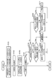
図2は、制御ユニット60が実行する処理を示すフローチャートである(適宜、図1を参照)。なお、図2に示す一連の処理は、空調システム100の試運転段階に行ってもよいし、通常の空調運転中に行ってもよい。
また、制御ユニット60側では、熱交換器32の熱交換性能(伝熱面積及び管内容積)や、それに基づく最適な風量が、事前に把握されていないことが多い。このような場合、制御ユニット60は、空調システム100の稼動初期において、予め設定された所定の回転速度で給気ファン33を駆動する。
図2は、制御ユニット60が実行する処理を示すフローチャートである(適宜、図1を参照)。なお、図2に示す一連の処理は、空調システム100の試運転段階に行ってもよいし、通常の空調運転中に行ってもよい。
また、制御ユニット60側では、熱交換器32の熱交換性能(伝熱面積及び管内容積)や、それに基づく最適な風量が、事前に把握されていないことが多い。このような場合、制御ユニット60は、空調システム100の稼動初期において、予め設定された所定の回転速度で給気ファン33を駆動する。
ステップS101において制御ユニット60は、冷媒温度センサ51の検出値Tg、及び冷媒温度センサ52の検出値Tqを読み込む。また、ステップS101において制御ユニット60は、空気温度センサ53の検出値Ts、及び空気温度センサ54の検出値Tdを読み込む。
ステップS102において制御ユニット60は、冷媒圧力Pを推定する。その一例を挙げると、制御ユニット60は、ステップS101で読み込んだ検出値Tg,Tqに基づき、液側の冷媒圧力P(熱交換器32で凝縮した冷媒の圧力)を算出する。
なお、冷媒回路Gに封入されている冷媒の物性(飽和圧力と飽和温度との関係)に関する情報が、制御ユニット60に予め記憶されている。ステップS102において制御ユニット60は、前記した冷媒の物性に関する情報や検出値Tg,Tqに基づいて、冷媒圧力Pを推定する。
なお、冷媒回路Gに封入されている冷媒の物性(飽和圧力と飽和温度との関係)に関する情報が、制御ユニット60に予め記憶されている。ステップS102において制御ユニット60は、前記した冷媒の物性に関する情報や検出値Tg,Tqに基づいて、冷媒圧力Pを推定する。
ステップS103において制御ユニット60は、ステップS101で読み込んだ検出値Tg,Tqに基づいて、冷媒温度差(Tg-Tq)を算出する。つまり、制御ユニット60は、熱交換器32の一端n側における冷媒の温度(検出値Tg)と、他端w側における冷媒の温度(検出値Tq)との差である冷媒温度差(Tg-Tq)を算出する。
また、ステップS103において制御ユニット60は、ステップS101で読み込んだ検出値Ts,Tdに基づいて、空気温度差(Ts-Td)を算出する。つまり、制御ユニット60は、熱交換器32における空気の吸込側の温度(検出値Ts)と、吹出側の温度(検出値Td)と、の差である空気温度差(Ts-Td)を算出する。
ステップS104において制御ユニット60は、冷媒回路Gにおける冷凍サイクルが適正な状態であるか否かを判定する。言い換えると、制御ユニット60は、前記した凝縮器や蒸発器において、熱交換が適切に行われているか否かを判定する。その一例を挙げると、制御ユニット60は、ステップS102で算出した冷媒圧力Pの他、ステップS103で算出した冷媒温度差(Tg-Tq)や空気温度差(Ts-Td)に基づいて、凝縮した冷媒の過冷却度や、蒸発した冷媒の過熱度を算出し、これらの値が適正な所定範囲内であるか否かを判定する。
ステップS104において冷凍サイクルが適正な状態である場合(S104:Yes)、制御ユニット60の処理は「START」に戻る(「RETURN」)。一方、ステップS104において冷凍サイクルが適正な状態でない場合(S104:No)、制御ユニット60の処理はステップS105に進む。
ステップS105において制御ユニット60は、空調能力が空調負荷に対して過大であるか否かを判定する。例えば、制御ユニット60は、冷房運転中において、リモコン70の操作に基づく設定温度Tsetから検出値Td(吹出側の空気温度)を減算した値ΔT=(Tset-Td)が所定閾値よりも大きい場合、空調能力が過大であると判定する。
ステップS105において空調能力が空調負荷に対して過大である場合(S105:Yes)、制御ユニット60の処理はステップS106に進む。例えば、伝熱面積や管内容積が大きい大容量の熱交換器32が用いられ、さらに、給気ファン33の風量が比較的大きいときには、空調能力が過大になる可能性がある。そのような状態が長時間続くと、被空調空間の冷え過ぎ又は温め過ぎといった事態が生じ得る。
ステップS106において制御ユニット60は、給気ファン33の現状の回転速度が、所定の回転速度下限値まで低下している否かを判定する。この回転速度下限値は、給気ファン33の回転速度の下限値であり、予め設定されている。
ステップS106において給気ファン33の現状の回転速度が回転速度下限値よりも大きい場合(S106:No)、制御ユニット60の処理はステップS107に進む。
ステップS107において制御ユニット60は、給気ファン33の回転速度を小さくする。これによって給気ファン33の風量が小さくなり、エアハンドリングユニット30の熱交換性能が抑えられるため、被空調空間が適度に空調される。
ステップS107において制御ユニット60は、給気ファン33の回転速度を小さくする。これによって給気ファン33の風量が小さくなり、エアハンドリングユニット30の熱交換性能が抑えられるため、被空調空間が適度に空調される。
一方、ステップS106において給気ファン33の現状の回転速度が回転速度下限値まで低下している場合(S106:Yes)、制御ユニット60の処理はステップS108に進む。
ステップS108において制御ユニット60は、警報表示の信号をリモコン70に送信する。すなわち、給気ファン33の回転速度を所定の回転速度下限値まで減少させても(S106:Yes)、空調能力が過大であるとき(S105:Yes)、制御ユニット60は、その旨をリモコン70に表示させる(S108)。このような警報表示が試運転段階でなされた場合、室外機10の接続対象となるエアハンドリングユニット30の仕様を変更してもよいし、また、冷媒回路Gに封入されている冷媒の量を少なくするようにしてもよい。これによって空調能力が抑制され、その後に適切な空調を行うことができる。
また、ステップS105において空調能力が空調負荷に対して過大でない場合(S105:No)、制御ユニット60の処理はステップS109に進む。つまり、空調システム100の空調能力が空調負荷に対して過小である場合、制御ユニット60の処理はステップS109に進む。例えば、伝熱面積や管内容積が小さい小容量の熱交換器32を用い、さらに、給気ファン33の風量が比較的小さいときには、空調能力が過小になる可能性がある。そのような状態が長時間続くと、被空調空間が冷えない、又は温まらないといった事態が生じ得る。
ステップS109において制御ユニット60は、給気ファン33の現状の回転速度が、所定の回転速度上限値に達しているか否かを判定する。この回転速度上限値は、給気ファン33の回転速度の上限値であり、予め設定されている。
ステップS109において給気ファン33の現状の回転速度が回転速度上限値よりも小さい場合(S109:No)、制御ユニット60は、給気ファン33の回転速度を大きくする。これによって給気ファン33の風量が大きくなり、エアハンドリングユニット30の熱交換性能が高められるため、被空調空間が適度に空調される。
一方、ステップS109において給気ファン33の現状の回転速度が回転速度上限値に達している場合(S109:Yes)、制御ユニット60の処理はステップS111に進む。
ステップS111において制御ユニット60は、警報表示の信号をリモコン70に送信する。すなわち、給気ファン33の回転速度を所定の回転速度上限値まで増加させても(S109:Yes)、空調能力が過小であるとき(S105:No)、制御ユニット60は、その旨をリモコン70に表示させる。このような警報表示が試運転段階でなされた場合、室外機10の接続対象となるエアハンドリングユニット30の仕様を変更してもよいし、また、追加の冷媒を冷媒回路Gに封入するようにしてもよい。これによって空調能力が高められ、その後に適切な空調を行うことができる。
また、ステップS111の警報表示が通常の空調運転中になされた場合には、熱交換器32の清掃等を要する旨をリモコン70に表示させてもよい。熱交換器32に付着した埃等を洗い流すことによって、エアハンドリングユニット30の熱交換性能を回復できることが多いからである。
ステップS104(Yes)、S107、S108、S110、又はS111の処理を行った後、制御ユニット60の処理は「START」に戻る(「RETURN」)。このようにして制御ユニット60は、図2に示す一連の処理を繰り返す。
<効果>
第1実施形態によれば、給気ファン33の回転速度を調整することによって(図2のS107、S110)、空調システム100の空調能力を適度な範囲内に収めることができる。例えば、大容量の熱交換器32を用いる場合には、給気ファン33を比較的小さい回転速度で駆動することで、適度な空調を行うことができる。一方、小容量の熱交換器32を用いる場合には、給気ファン33を比較的大きい回転速度で駆動することで、適度な空調を行うことができる。したがって、さまざまな仕様のエアハンドリングユニット30が室外機10に接続可能になる。このように、第1実施形態によれば、信頼性が高く、また、エアハンドリングユニット30を選定する際の自由度が高い空調システム100を提供できる。
第1実施形態によれば、給気ファン33の回転速度を調整することによって(図2のS107、S110)、空調システム100の空調能力を適度な範囲内に収めることができる。例えば、大容量の熱交換器32を用いる場合には、給気ファン33を比較的小さい回転速度で駆動することで、適度な空調を行うことができる。一方、小容量の熱交換器32を用いる場合には、給気ファン33を比較的大きい回転速度で駆動することで、適度な空調を行うことができる。したがって、さまざまな仕様のエアハンドリングユニット30が室外機10に接続可能になる。このように、第1実施形態によれば、信頼性が高く、また、エアハンドリングユニット30を選定する際の自由度が高い空調システム100を提供できる。
また、従来技術である特許文献1のように圧縮機を複数台設ける必要がなく、制御ユニット60の処理も比較的簡素であるため、空調システム100の低コスト化を図ることができる。
また、給気ファン33の回転速度を回転速度下限値まで減少させても(図2のS106:Yes)、空調能力が過大である場合(S105:Yes)、その旨がリモコン70に表示される(S108)。一方、給気ファン33の回転速度を回転速度上限値まで増加させても(S109:Yes)、空調能力が過小である場合(S105:No)、その旨がリモコン70に表示される(S111)。これによって、冷媒回路Gに封入されている冷媒の量を試運転段階で調整したり、その後の空調運転時に所定のメンテナンスをユーザに喚起したりすることができる。
≪第2実施形態≫
第2実施形態は、膨張弁41(図1参照)の開度調整によって空調能力を増減させる点が第1実施形態とは異なっているが、その他(空調システム100の構成等:図1参照)については第1実施形態と同様である。したがって、第1実施形態とは異なる部分について説明し、重複する部分については説明を省略する。
第2実施形態は、膨張弁41(図1参照)の開度調整によって空調能力を増減させる点が第1実施形態とは異なっているが、その他(空調システム100の構成等:図1参照)については第1実施形態と同様である。したがって、第1実施形態とは異なる部分について説明し、重複する部分については説明を省略する。
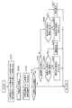
図3は、制御ユニット60が実行する処理を示すフローチャートである(適宜、図1を参照)。なお、第1実施形態(図2参照)と同様の処理には、同一のステップ番号を付している。
ステップS104において制御ユニット60は、冷媒回路Gにおける冷凍サイクルが適正な状態であるか否かを判定する。冷凍サイクルが適正な状態でない場合(S104:No)、制御ユニット60の処理はステップS105に進む。
ステップS104において制御ユニット60は、冷媒回路Gにおける冷凍サイクルが適正な状態であるか否かを判定する。冷凍サイクルが適正な状態でない場合(S104:No)、制御ユニット60の処理はステップS105に進む。
ステップS105において制御ユニット60は、空調能力が空調負荷に対して過大であるか否かを判定する。なお、空調能力が過大(又は過小)であるか否かの判定方法は、第1実施形態で説明したとおりである。ステップS105において空調能力が空調負荷に対して過大である場合(S105:Yes)、制御ユニット60の処理はステップS206に進む。例えば、大容量の熱交換器32を用いると、冷媒回路Gを循環する冷媒の流量が過多になりやすく、結果的に空調能力が過大になりやすい。
ステップS206において制御ユニット60は、膨張弁41の現状の開度が、所定の開度下限値まで低下しているか否かを判定する。この開度下限値は、膨張弁41の開度の下限値であり、予め設定されている。
ステップS206において膨張弁41の現状の開度が開度下限値よりも大きい場合(S206:No)、制御ユニット60の処理はステップS207に進む。
ステップS207において制御ユニット60は、膨張弁41の開度を小さくする。これによって、冷媒回路Gにおける冷媒の循環流量が小さくなるため、空調能力が抑えられ、被空調空間が適度に空調される。
ステップS207において制御ユニット60は、膨張弁41の開度を小さくする。これによって、冷媒回路Gにおける冷媒の循環流量が小さくなるため、空調能力が抑えられ、被空調空間が適度に空調される。
一方、ステップS206において膨張弁41の現状の開度が開度下限値まで低下している場合(S206:Yes)、制御ユニット60の処理はステップS208に進む。
ステップS208において制御ユニット60は、警報表示の信号をリモコン70に送信する。すなわち、膨張弁41の開度を所定の開度下限値まで減少させても(S206:Yes)、空調能力が過大であるとき(S105:Yes)、制御ユニット60は、その旨をリモコン70に表示させる(S208)。このような警報表示が試運転段階でなされた場合、室外機10の接続対象となるエアハンドリングユニット30の仕様を変更してもよいし、また、冷媒回路Gに封入されている冷媒の量を少なくするようにしてもよい。これによって空調能力が抑制され、その後に適切な空調を行うことができる。
また、ステップS105において空調能力が空調負荷に対して過大ではなく、過小である場合(S105:No)、制御ユニット60の処理はステップS209に進む。例えば、小容量の熱交換器32を用いると、冷媒回路Gを循環する冷媒の流量が過少になりやすく、結果的に空調能力が過小になりやすい。
ステップS209において制御ユニット60は、膨張弁41の現状の開度が、所定の開度上限値に達しているか否かを判定する。この開度上限値は、膨張弁41の開度の上限値であり、予め設定されている。
ステップS209において制御ユニット60は、膨張弁41の現状の開度が、所定の開度上限値に達しているか否かを判定する。この開度上限値は、膨張弁41の開度の上限値であり、予め設定されている。
ステップS209において膨張弁41の開度が開度上限値よりも小さい場合(S209:No)、制御ユニット60の処理はステップS210に進む。
ステップS210において制御ユニット60は、膨張弁41の開度を大きくする。これによって、冷媒回路Gにおける冷媒の循環流量が大きくなるため、空調能力が増大し、被空調空間が適度に空調される。
ステップS210において制御ユニット60は、膨張弁41の開度を大きくする。これによって、冷媒回路Gにおける冷媒の循環流量が大きくなるため、空調能力が増大し、被空調空間が適度に空調される。
一方、ステップS209において膨張弁41の開度が開度上限値に達している場合(S209:Yes)、制御ユニット60の処理はステップS211に進む。
ステップS211において制御ユニット60は、警報表示の信号をリモコン70に送信する。すなわち、膨張弁41の開度を所定の開度上限値まで増加させても(S209:Yes)、空調能力が過小であるとき(S105:No)、制御ユニット60は、その旨をリモコン70に表示させる(S211)。これによって、試運転段階における冷媒の追加や、その後の空調運転時におけるメンテナンスをユーザに喚起できる。
ステップS211において制御ユニット60は、警報表示の信号をリモコン70に送信する。すなわち、膨張弁41の開度を所定の開度上限値まで増加させても(S209:Yes)、空調能力が過小であるとき(S105:No)、制御ユニット60は、その旨をリモコン70に表示させる(S211)。これによって、試運転段階における冷媒の追加や、その後の空調運転時におけるメンテナンスをユーザに喚起できる。
ステップS104(Yes)、S207、S208、S210、又はS211の処理を行った後、制御ユニット60の処理は「START」に戻る(「RETURN」)。このようにして制御ユニット60は、図3に示す一連の処理を繰り返す。
<効果>
第2実施形態によれば、膨張弁41の開度を調整することによって(図3のS207、S210)、空調システム100の空調能力を適度な範囲内に収めることができる。したがって、さまざまな仕様のエアハンドリングユニット30が室外機10に接続可能になるため、エアハンドリングユニット30を選定する際の自由度を従来よりも高めることができる。
第2実施形態によれば、膨張弁41の開度を調整することによって(図3のS207、S210)、空調システム100の空調能力を適度な範囲内に収めることができる。したがって、さまざまな仕様のエアハンドリングユニット30が室外機10に接続可能になるため、エアハンドリングユニット30を選定する際の自由度を従来よりも高めることができる。
また、膨張弁41の開度を開度下限値まで減少させても(S206:Yes)、空調能力が過大である場合(S105:Yes)、その旨がリモコン70に表示される(S208)。一方、膨張弁41の開度を開度上限値まで増加させても(S209:Yes)、空調能力が過小である場合(S105:No)、その旨がリモコン70に表示される(S211)。これによって、冷媒回路Gに封入されている冷媒の量を試運転段階で調整したり、また、その後の空調運転時に所定のメンテナンスをユーザに喚起したりすることができる。
≪第3実施形態≫
第3実施形態は、冷媒の温度検出値に基づいて冷媒漏れを検知する点が第1実施形態とは異なっているが、その他(空調システム100の構成等:図1参照)については第1実施形態と同様である。したがって、第1実施形態とは異なる部分について説明し、重複する部分については説明を省略する。
第3実施形態は、冷媒の温度検出値に基づいて冷媒漏れを検知する点が第1実施形態とは異なっているが、その他(空調システム100の構成等:図1参照)については第1実施形態と同様である。したがって、第1実施形態とは異なる部分について説明し、重複する部分については説明を省略する。
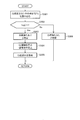
図4は、制御ユニット60が実行する処理を示すフローチャートである(適宜、図1を参照)。なお、図4に示す一連の処理中、暖房運転が行われている(つまり、熱交換器32が凝縮器として機能している)ものとする。
また、図4に示す一連の処理は、第1実施形態で説明した制御ユニット60の処理(図2参照)と並行して行われる。
また、図4に示す一連の処理は、第1実施形態で説明した制御ユニット60の処理(図2参照)と並行して行われる。
ステップS301において制御ユニット60は、冷媒温度センサ52の検出値Tqを読み込む。すなわち、制御ユニット60は、凝縮器である熱交換器32で熱交換した冷媒の温度(検出値Tq)を読み込む。
ステップS302において制御ユニット60は、ステップS301で読み込んだ検出値Tqが所定閾値T1以下であるか否かを判定する。この所定閾値T1は、冷媒回路Gにおいて冷媒漏れが生じているか否かの判定基準となる閾値であり、予め設定されている。
ステップS302において検出値Tqが所定閾値T1以下である場合(S302:Yes)、制御ユニット60の処理はステップS303に進む。仮に、冷媒漏れが生じた場合、冷媒回路Gに封入されている冷媒の量が正常時よりも少なくなる。その結果、熱交換器32で凝縮する際に冷媒が冷やされ過ぎて、冷媒の温度が正常時よりも低くなることが多い。
ステップS303において制御ユニット60は、冷媒回路Gにおいて「冷媒漏れあり」と判定する。なお、冷媒温度センサ52の検出値Tqに加えて、圧縮機11のモータ(図示せず)の回転速度、室外膨張弁16や膨張弁41の開度、その他の各センサの検出値等に基づき、制御ユニット60が冷媒漏れの有無を判定するようにしてもよい。
ステップS304において制御ユニット60は、圧縮機11を停止させるとともに、膨張弁41を閉止する。これによって、冷媒回路Gにおける冷媒の流れを止める(つまり、空調運転を強制的に停止させる)ことができる。
ステップS305において制御ユニット60は、冷媒漏れを報知するための信号をリモコン70に送信する。これによって、冷媒回路Gで冷媒漏れが発生している旨がリモコン70に表示される。したがって、配管の取替え等のメンテナンスを要する旨をユーザに報知できる。
また、ステップS302において検出値Tqが所定閾値T1よりも高い場合(S302:No)、制御ユニット60の処理はステップS306に進む。
ステップS306において制御ユニット60は、冷媒回路Gにおいて「冷媒漏れなし」と判定し、空調運転を継続する。
ステップS305又はS306の処理を行った後、制御ユニット60の処理は「START」に戻る(「RETURN」)。このようにして制御ユニット60は、図4に示す一連の処理を繰り返す。
ステップS306において制御ユニット60は、冷媒回路Gにおいて「冷媒漏れなし」と判定し、空調運転を継続する。
ステップS305又はS306の処理を行った後、制御ユニット60の処理は「START」に戻る(「RETURN」)。このようにして制御ユニット60は、図4に示す一連の処理を繰り返す。
<効果>
第3実施形態によれば、冷媒漏れが検知された場合(図4のS302:Yes、S303)、圧縮機11が停止されるとともに、膨張弁41が閉止される(S304)。これによって、冷媒漏れが生じたまま空調運転が継続されることを防止できる。また、冷媒漏れが検知された場合、その旨がリモコン70によってユーザに報知される(S304)。したがって、第3実施形態によれば、空調システム100の信頼性を第1実施形態よりも高めることができる。
第3実施形態によれば、冷媒漏れが検知された場合(図4のS302:Yes、S303)、圧縮機11が停止されるとともに、膨張弁41が閉止される(S304)。これによって、冷媒漏れが生じたまま空調運転が継続されることを防止できる。また、冷媒漏れが検知された場合、その旨がリモコン70によってユーザに報知される(S304)。したがって、第3実施形態によれば、空調システム100の信頼性を第1実施形態よりも高めることができる。
≪変形例≫
以上、本発明に係る空調システム100について各実施形態で説明したが、本発明はこれらの記載に限定されるものではなく、種々の変更を行うことができる。
例えば、各実施形態では、図1に示す室外機10が、過冷却器23、過冷却用膨張弁24、及び配管k7,k8を備える構成について説明したが、これらを適宜に省略してもよい。
また、各実施形態では、室外機10が、オイルセパレータ17、逆止弁19、キャピラリチューブ18,22、二方弁21、及び配管k3,k5を備える構成について説明したが、これらのうち一部又は全部を適宜に省略してもよい。
また、各実施形態では、室外機10が四方弁15を備える構成について説明したが、これに限らない。すなわち、四方弁15を省略し、冷房専用又は暖房専用の構成にしてもよい。
また、各実施形態では、空調システム100が、室外膨張弁16と、減圧装置40の膨張弁41と、を備える構成について説明したが、これらのうち一方を省略してもよい。すなわち、室外機10が、少なくとも圧縮機11及び室外熱交換器13を有する構成にしてもよい。つまり、圧縮機11、室外熱交換器13(第1熱交換器)、膨張弁41、及び熱交換器32(第2熱交換器)が環状に順次接続されてなる冷媒回路において、冷凍サイクルで冷媒が循環する構成になっていればよい。なお、前記した構成は、図1に示す冷媒回路Gの構成を含むものである。
以上、本発明に係る空調システム100について各実施形態で説明したが、本発明はこれらの記載に限定されるものではなく、種々の変更を行うことができる。
例えば、各実施形態では、図1に示す室外機10が、過冷却器23、過冷却用膨張弁24、及び配管k7,k8を備える構成について説明したが、これらを適宜に省略してもよい。
また、各実施形態では、室外機10が、オイルセパレータ17、逆止弁19、キャピラリチューブ18,22、二方弁21、及び配管k3,k5を備える構成について説明したが、これらのうち一部又は全部を適宜に省略してもよい。
また、各実施形態では、室外機10が四方弁15を備える構成について説明したが、これに限らない。すなわち、四方弁15を省略し、冷房専用又は暖房専用の構成にしてもよい。
また、各実施形態では、空調システム100が、室外膨張弁16と、減圧装置40の膨張弁41と、を備える構成について説明したが、これらのうち一方を省略してもよい。すなわち、室外機10が、少なくとも圧縮機11及び室外熱交換器13を有する構成にしてもよい。つまり、圧縮機11、室外熱交換器13(第1熱交換器)、膨張弁41、及び熱交換器32(第2熱交換器)が環状に順次接続されてなる冷媒回路において、冷凍サイクルで冷媒が循環する構成になっていればよい。なお、前記した構成は、図1に示す冷媒回路Gの構成を含むものである。
また、各実施形態では、警報表示等を行うための信号が制御ユニット60からリモコン70に送信される場合について説明したが、これに限らない。すなわち、警報表示等を行うための信号を制御ユニット60が室外制御回路25に送信し、室外機10側で7セグメント表示等によって所定の報知を行うようにしてもよい。
また、各実施形態では、室外機10とエアハンドリングユニット30が一台ずつ設けられる構成について説明したが、これに限らない。すなわち、複数台の室外機10を並列接続してもよいし、また、複数台のエアハンドリングユニット30を並列接続してもよい。
また、第3実施形態では、暖房運転中、冷媒温度センサ52の検出値Tqが所定閾値T1以下であるとき(図4のS302:Yes)、制御ユニット60が「冷媒漏れあり」と判定する処理(S303)について説明したが、これに限らない。例えば、冷房運転中、冷媒温度センサ51の検出値Tgが所定閾値以上である場合、制御ユニット60が「冷媒漏れあり」と判定するようにしてもよい。言い換えると、熱交換器32が蒸発器として機能している場合において、熱交換器32で熱交換した冷媒の温度検出値が所定閾値以上であるとき、制御ユニット60が「冷媒漏れあり」と判定するようにしてもよい。冷媒漏れが生じているときには、蒸発器である熱交換器32において、冷媒の温度が過度に上昇することが多いからである。前記したように、「冷媒漏れあり」と判定した場合、制御ユニット60は、圧縮機11を停止させるとともに、膨張弁41を閉止し、さらに、冷媒回路Gで冷媒漏れが生じている旨をリモコン70に表示させる。
また、各実施形態は、適宜組み合わせることができる。
例えば、第1実施形態と第2実施形態とを組み合わせ、空調能力が過大である場合には、制御ユニット60が、給気ファン33の回転速度を小さくするとともに、膨張弁41の開度を小さくするようにしてもよい。これによって、空調能力を抑制し、被空調空間を適度に空調できる。
一方、空調能力が過小である場合には、制御ユニット60が、給気ファン33の回転速度を大きくするとともに、膨張弁41の開度を大きくするようにしてもよい。これによって、空調能力を高め、被空調空間を適度に空調できる。このように、制御ユニット60が、冷媒温度センサ51,52及び空気温度センサ53,54の検出値を含む情報に基づいて、給気ファン33の回転速度及び/又は膨張弁41の開度を調整するようにしてもよい。
例えば、第1実施形態と第2実施形態とを組み合わせ、空調能力が過大である場合には、制御ユニット60が、給気ファン33の回転速度を小さくするとともに、膨張弁41の開度を小さくするようにしてもよい。これによって、空調能力を抑制し、被空調空間を適度に空調できる。
一方、空調能力が過小である場合には、制御ユニット60が、給気ファン33の回転速度を大きくするとともに、膨張弁41の開度を大きくするようにしてもよい。これによって、空調能力を高め、被空調空間を適度に空調できる。このように、制御ユニット60が、冷媒温度センサ51,52及び空気温度センサ53,54の検出値を含む情報に基づいて、給気ファン33の回転速度及び/又は膨張弁41の開度を調整するようにしてもよい。
また、第2実施形態と第3実施形態とを組み合わせ、空調能力に基づいて膨張弁41の開度を調整しつつ(第2実施形態)、冷媒漏れを検知するようにしてもよい(第3実施形態)。
また、各実施形態は本発明を分かりやすく説明するために詳細に記載したものであり、必ずしも説明した全ての構成を備えるものに限定されない。また、各実施形態の構成の一部について、他の構成の追加・削除・置換をすることが可能である。
また、前記した機構や構成は説明上必要と考えられるものを示しており、製品上必ずしも全ての機構や構成を示しているとは限らない。
また、前記した機構や構成は説明上必要と考えられるものを示しており、製品上必ずしも全ての機構や構成を示しているとは限らない。
100 空調システム(空調装置)
10 室外機
11 圧縮機
12 アキュムレータ
13 室外熱交換器(第1熱交換器)
30 エアハンドリングユニット
31 筐体
32 熱交換器(第2熱交換器)
33 給気ファン
40 減圧装置
41 膨張弁
51 冷媒温度センサ
52 冷媒温度センサ
53 空気温度センサ
54 空気温度センサ
60 制御ユニット(制御部、制御装置)
70 リモコン(表示部)
G 冷媒回路
n 一端(第2熱交換器の一端)
w 他端(第2熱交換器の他端)
10 室外機
11 圧縮機
12 アキュムレータ
13 室外熱交換器(第1熱交換器)
30 エアハンドリングユニット
31 筐体
32 熱交換器(第2熱交換器)
33 給気ファン
40 減圧装置
41 膨張弁
51 冷媒温度センサ
52 冷媒温度センサ
53 空気温度センサ
54 空気温度センサ
60 制御ユニット(制御部、制御装置)
70 リモコン(表示部)
G 冷媒回路
n 一端(第2熱交換器の一端)
w 他端(第2熱交換器の他端)
Claims (8)
- 少なくとも圧縮機及び第1熱交換器を有する室外機と、
給気ファン及び第2熱交換器を有するエアハンドリングユニットと、
膨張弁と、
制御部と、を備え、
前記圧縮機、前記第1熱交換器、前記膨張弁、及び前記第2熱交換器が環状に順次接続されて冷媒が循環される冷媒回路を有し、
前記制御部は、前記第2熱交換器の一端側・他端側のそれぞれにおける冷媒の温度検出値、前記第2熱交換器に向かう空気の温度検出値、及び前記第2熱交換器で熱交換した空気の温度検出値を含む情報に基づいて、前記給気ファンの回転速度及び/又は前記膨張弁の開度を調整すること
を特徴とする空調システム。 - 前記制御部は、前記給気ファンの回転速度を調整する場合において、
前記情報に基づく空調能力が空調負荷に対して過大であるときには、前記給気ファンの回転速度を小さくし、
前記情報に基づく空調能力が空調負荷に対して過小であるときには、前記給気ファンの回転速度を大きくすること
を特徴とする請求項1に記載の空調システム。 - 空調に関する所定の表示を行う表示部を備え、
前記制御部は、
前記給気ファンの回転速度を所定の回転速度下限値まで減少させても、前記空調能力が過大であるときには、その旨を前記表示部に表示させ、
前記給気ファンの回転速度を所定の回転速度上限値まで増加させても、前記空調能力が過小であるときには、その旨を前記表示部に表示させること
を特徴とする請求項2に記載の空調システム。 - 前記制御部は、前記膨張弁の開度を調整する場合において、
前記情報に基づく空調能力が空調負荷に対して過大であるときには、前記膨張弁の開度を小さくし、
前記情報に基づく空調能力が空調負荷に対して過小であるときには、前記膨張弁の開度を大きくすること
を特徴とする請求項1に記載の空調システム。 - 空調に関する所定の表示を行う表示部を備え、
前記制御部は、
前記膨張弁の開度を所定の開度下限値まで減少させても、前記空調能力が過大であるときには、その旨を前記表示部に表示させ、
前記膨張弁の開度を所定の開度上限値まで増加させても、前記空調能力が過小であるときには、その旨を前記表示部に表示させること
を特徴とする請求項4に記載の空調システム。 - 空調に関する所定の表示を行う表示部を備え、
前記制御部は、
前記第2熱交換器が凝縮器として機能している場合において、前記第2熱交換器で熱交換した冷媒の温度検出値が所定閾値以下であるとき、
又は、
前記第2熱交換器が蒸発器として機能している場合において、前記第2熱交換器で熱交換した冷媒の温度検出値が所定閾値以上であるとき、
前記圧縮機を停止させるとともに前記膨張弁を閉止し、さらに、前記冷媒回路で冷媒漏れが生じている旨を前記表示部に表示させること
を特徴とする請求項1に記載の空調システム。 - 少なくとも圧縮機及び第1熱交換器を有する室外機と、給気ファン及び第2熱交換器を有するエアハンドリングユニットと、膨張弁と、制御部と、を備え、前記圧縮機、前記第1熱交換器、前記膨張弁、及び前記第2熱交換器が環状に順次接続されて冷媒が循環される冷媒回路を有する空調システムの前記制御部が実行する空調方法であって、
前記制御部は、前記第2熱交換器の一端側・他端側のそれぞれにおける冷媒の温度検出値、前記第2熱交換器に向かう空気の温度検出値、及び前記第2熱交換器で熱交換した空気の温度検出値を含む情報に基づいて、前記給気ファンの回転速度及び/又は前記膨張弁の開度を調整すること
を特徴とする空調方法。 - 少なくとも圧縮機及び第1熱交換器を有する室外機と、給気ファン及び第2熱交換器を有するエアハンドリングユニットと、膨張弁と、を備え、前記圧縮機、前記第1熱交換器、前記膨張弁、及び前記第2熱交換器が環状に順次接続されて冷媒が循環される冷媒回路を有する空調装置に制御信号を出力する制御装置であって、
前記第2熱交換器の一端側・他端側のそれぞれにおける冷媒の温度検出値、前記第2熱交換器に向かう空気の温度検出値、及び前記第2熱交換器で熱交換した空気の温度検出値を含む情報に基づいて、前記給気ファンの回転速度及び/又は前記膨張弁の開度を調整する制御装置。
Priority Applications (4)
| Application Number | Priority Date | Filing Date | Title |
|---|---|---|---|
| JP2018542305A JP6685415B2 (ja) | 2017-06-12 | 2018-05-23 | 空調システム、空調方法、及び制御装置 |
| CN201880001988.XA CN109392304B (zh) | 2017-06-12 | 2018-05-23 | 空调系统、空调方法以及控制装置 |
| EP18817745.5A EP3640557A4 (en) | 2017-06-12 | 2018-05-23 | AIR CONDITIONING SYSTEM, AIR CONDITIONING PROCEDURES AND CONTROL DEVICE |
| US16/278,902 US11015834B2 (en) | 2017-06-12 | 2019-02-19 | Air conditioning system, air conditioning method, and control device |
Applications Claiming Priority (2)
| Application Number | Priority Date | Filing Date | Title |
|---|---|---|---|
| JP2017115048 | 2017-06-12 | ||
| JP2017-115048 | 2017-06-12 |
Related Child Applications (1)
| Application Number | Title | Priority Date | Filing Date |
|---|---|---|---|
| US16/278,902 Continuation US11015834B2 (en) | 2017-06-12 | 2019-02-19 | Air conditioning system, air conditioning method, and control device |
Publications (1)
| Publication Number | Publication Date |
|---|---|
| WO2018230281A1 true WO2018230281A1 (ja) | 2018-12-20 |
Family
ID=64659650
Family Applications (1)
| Application Number | Title | Priority Date | Filing Date |
|---|---|---|---|
| PCT/JP2018/019740 Ceased WO2018230281A1 (ja) | 2017-06-12 | 2018-05-23 | 空調システム、空調方法、及び制御装置 |
Country Status (5)
| Country | Link |
|---|---|
| US (1) | US11015834B2 (ja) |
| EP (1) | EP3640557A4 (ja) |
| JP (1) | JP6685415B2 (ja) |
| CN (1) | CN109392304B (ja) |
| WO (1) | WO2018230281A1 (ja) |
Cited By (2)
| Publication number | Priority date | Publication date | Assignee | Title |
|---|---|---|---|---|
| CN115789994A (zh) * | 2021-09-10 | 2023-03-14 | 松下电器研究开发(苏州)有限公司 | 空调压缩机的润滑油控制方法 |
| WO2023243089A1 (ja) * | 2022-06-17 | 2023-12-21 | 三菱電機株式会社 | 空気調和装置 |
Families Citing this family (14)
| Publication number | Priority date | Publication date | Assignee | Title |
|---|---|---|---|---|
| US20190186769A1 (en) * | 2017-12-18 | 2019-06-20 | Heatcraft Refrigeration Products Llc | Cooling system |
| WO2019211905A1 (ja) * | 2018-05-02 | 2019-11-07 | 三菱電機株式会社 | 空気調和装置 |
| JP6750696B2 (ja) * | 2019-01-31 | 2020-09-02 | ダイキン工業株式会社 | 冷媒サイクル装置 |
| US11231198B2 (en) | 2019-09-05 | 2022-01-25 | Trane International Inc. | Systems and methods for refrigerant leak detection in a climate control system |
| US20210207831A1 (en) * | 2019-09-12 | 2021-07-08 | Carrier Corporation | Refrigerant leak detection and mitigation |
| CN111237986B (zh) * | 2020-01-13 | 2022-01-04 | 广东积微科技有限公司 | 空调显示装置及空调 |
| US20230070076A1 (en) * | 2020-03-02 | 2023-03-09 | AC Companion LLC | Enhanced air conditioning chiller system |
| KR102438931B1 (ko) * | 2020-12-11 | 2022-08-31 | 엘지전자 주식회사 | 공기조화기 및 그 제어방법 |
| CN113551369B (zh) * | 2021-07-09 | 2022-04-26 | 珠海格力电器股份有限公司 | 一种用于检测制冷系统堵塞的控制系统及堵塞检测方法 |
| US12487008B2 (en) | 2022-01-14 | 2025-12-02 | Trane International Inc. | Method of commissioning an HVAC system |
| US12117191B2 (en) | 2022-06-24 | 2024-10-15 | Trane International Inc. | Climate control system with improved leak detector |
| EP4686899A1 (en) * | 2024-08-02 | 2026-02-04 | BDR Thermea Group B.V. | Controller, method, computer program product and non transitory computer readable medium for monitoring leakage of refrigerant, heat pump comprsing the controller |
| EP4686898A1 (en) * | 2024-08-02 | 2026-02-04 | BDR Thermea Group B.V. | Controller, method, computer program product and non transitory computer readable medium for monitoring leakage of refrigerant, heat pump comprsing the controller |
| WO2026027766A1 (en) * | 2024-08-02 | 2026-02-05 | Bdr Thermea Group B.V. | Heat pump with malfunction detection system |
Citations (7)
| Publication number | Priority date | Publication date | Assignee | Title |
|---|---|---|---|---|
| JPH09273797A (ja) * | 1996-04-04 | 1997-10-21 | Hitachi Ltd | 多室空気調和機 |
| JP2007263483A (ja) * | 2006-03-29 | 2007-10-11 | Yamatake Corp | 可変給気量制御確認装置および方法 |
| WO2009011197A1 (ja) * | 2007-07-18 | 2009-01-22 | Mitsubishi Electric Corporation | 冷凍サイクル装置およびその運転制御方法 |
| WO2015166576A1 (ja) * | 2014-05-01 | 2015-11-05 | 三菱電機株式会社 | 空気調和装置 |
| JP2016114286A (ja) * | 2014-12-15 | 2016-06-23 | ジョンソンコントロールズ ヒタチ エア コンディショニング テクノロジー(ホンコン)リミテッド | 空気調和機 |
| JP2017053566A (ja) * | 2015-09-10 | 2017-03-16 | ジョンソンコントロールズ ヒタチ エア コンディショニング テクノロジー(ホンコン)リミテッド | 冷凍サイクル装置 |
| US20170153037A1 (en) * | 2015-11-30 | 2017-06-01 | Lennox Industries LLC | Method and apparatus for reheat dehumidification with variable air volume |
Family Cites Families (25)
| Publication number | Priority date | Publication date | Assignee | Title |
|---|---|---|---|---|
| JPS57207773A (en) * | 1981-06-17 | 1982-12-20 | Taiheiyo Kogyo Kk | Method of controlling cooling circuit and its control valve |
| US5392612A (en) * | 1984-08-08 | 1995-02-28 | Richard H. Alsenz | Refrigeration system having a self adjusting control range |
| US4651535A (en) * | 1984-08-08 | 1987-03-24 | Alsenz Richard H | Pulse controlled solenoid valve |
| US5402652A (en) * | 1984-08-08 | 1995-04-04 | Alsenz; Richard H. | Apparatus for monitoring solenoid expansion valve flow rates |
| JP2824297B2 (ja) * | 1989-12-01 | 1998-11-11 | 株式会社日立製作所 | 空気調和機のセンサ異常時の運転方式 |
| US6105379A (en) * | 1994-08-25 | 2000-08-22 | Altech Controls Corporation | Self-adjusting valve |
| DE10021610A1 (de) * | 2000-05-04 | 2001-11-08 | Linde Ag | Verfahren zum Betreiben einer (Verbund)Kälteanlage |
| JP3815199B2 (ja) * | 2000-09-26 | 2006-08-30 | ダイキン工業株式会社 | 空気調和機 |
| CN100513941C (zh) * | 2001-09-19 | 2009-07-15 | 株式会社东芝 | 制冷冰箱的控制装置和冷媒泄漏判断方法 |
| ITTO20030792A1 (it) * | 2002-10-08 | 2004-04-09 | Danfoss As | Dispositivo e procedimento di controllo di una valvola |
| JP2004347247A (ja) * | 2003-05-23 | 2004-12-09 | Fujitsu General Ltd | 空気調和機の制御方法 |
| US7380404B2 (en) * | 2005-01-05 | 2008-06-03 | Carrier Corporation | Method and control for determining low refrigerant charge |
| JP2010007996A (ja) * | 2008-06-27 | 2010-01-14 | Daikin Ind Ltd | 空気調和装置の試運転方法および空気調和装置 |
| US9459029B2 (en) * | 2009-01-19 | 2016-10-04 | Fujikoki Corporation | Valve controller, valve controlling method, refrigeration and cold storage system, device and method for controlling the system |
| JP2011255831A (ja) * | 2010-06-11 | 2011-12-22 | Sanden Corp | 車両用空調装置及び車両用空調装置の冷媒漏出診断方法 |
| JP5511717B2 (ja) * | 2011-03-14 | 2014-06-04 | 三菱電機株式会社 | 空気調和機 |
| US9970696B2 (en) * | 2011-07-20 | 2018-05-15 | Thermo King Corporation | Defrost for transcritical vapor compression system |
| EP2888541B1 (en) * | 2012-08-23 | 2020-04-29 | Danfoss A/S | A method for controlling a vapour compression system during start-up |
| CN105378392B (zh) * | 2013-05-27 | 2018-10-26 | 三菱电机株式会社 | 空调装置 |
| US9638434B2 (en) * | 2013-09-18 | 2017-05-02 | Alaska Structures, Inc. | Environment control system and devices |
| JP6249932B2 (ja) | 2014-12-04 | 2017-12-20 | 三菱電機株式会社 | 空調システム |
| EP3124897B1 (en) * | 2015-07-27 | 2018-02-21 | Honeywell spol s.r.o. | Methods and apparatus for vapor compression circuit control |
| CN108027185B (zh) * | 2015-10-27 | 2020-06-05 | 株式会社电装 | 制冷循环装置 |
| US10663200B2 (en) | 2016-01-13 | 2020-05-26 | Danfoss A/S | Method for controlling a supply of refrigerant to an evaporator in contingency mode |
| CN105546771B (zh) * | 2016-02-29 | 2018-05-08 | 美的集团武汉制冷设备有限公司 | 空调器冷媒泄漏检测的方法和装置 |
-
2018
- 2018-05-23 EP EP18817745.5A patent/EP3640557A4/en active Pending
- 2018-05-23 JP JP2018542305A patent/JP6685415B2/ja active Active
- 2018-05-23 WO PCT/JP2018/019740 patent/WO2018230281A1/ja not_active Ceased
- 2018-05-23 CN CN201880001988.XA patent/CN109392304B/zh active Active
-
2019
- 2019-02-19 US US16/278,902 patent/US11015834B2/en active Active
Patent Citations (7)
| Publication number | Priority date | Publication date | Assignee | Title |
|---|---|---|---|---|
| JPH09273797A (ja) * | 1996-04-04 | 1997-10-21 | Hitachi Ltd | 多室空気調和機 |
| JP2007263483A (ja) * | 2006-03-29 | 2007-10-11 | Yamatake Corp | 可変給気量制御確認装置および方法 |
| WO2009011197A1 (ja) * | 2007-07-18 | 2009-01-22 | Mitsubishi Electric Corporation | 冷凍サイクル装置およびその運転制御方法 |
| WO2015166576A1 (ja) * | 2014-05-01 | 2015-11-05 | 三菱電機株式会社 | 空気調和装置 |
| JP2016114286A (ja) * | 2014-12-15 | 2016-06-23 | ジョンソンコントロールズ ヒタチ エア コンディショニング テクノロジー(ホンコン)リミテッド | 空気調和機 |
| JP2017053566A (ja) * | 2015-09-10 | 2017-03-16 | ジョンソンコントロールズ ヒタチ エア コンディショニング テクノロジー(ホンコン)リミテッド | 冷凍サイクル装置 |
| US20170153037A1 (en) * | 2015-11-30 | 2017-06-01 | Lennox Industries LLC | Method and apparatus for reheat dehumidification with variable air volume |
Non-Patent Citations (1)
| Title |
|---|
| See also references of EP3640557A4 * |
Cited By (2)
| Publication number | Priority date | Publication date | Assignee | Title |
|---|---|---|---|---|
| CN115789994A (zh) * | 2021-09-10 | 2023-03-14 | 松下电器研究开发(苏州)有限公司 | 空调压缩机的润滑油控制方法 |
| WO2023243089A1 (ja) * | 2022-06-17 | 2023-12-21 | 三菱電機株式会社 | 空気調和装置 |
Also Published As
| Publication number | Publication date |
|---|---|
| JP6685415B2 (ja) | 2020-04-22 |
| US11015834B2 (en) | 2021-05-25 |
| JPWO2018230281A1 (ja) | 2019-06-27 |
| CN109392304A (zh) | 2019-02-26 |
| CN109392304B (zh) | 2021-04-20 |
| EP3640557A4 (en) | 2021-03-17 |
| EP3640557A1 (en) | 2020-04-22 |
| US20190186777A1 (en) | 2019-06-20 |
Similar Documents
| Publication | Publication Date | Title |
|---|---|---|
| JP6685415B2 (ja) | 空調システム、空調方法、及び制御装置 | |
| JP6230931B2 (ja) | マルチ形空気調和機 | |
| JP6878612B2 (ja) | 冷凍サイクル装置 | |
| EP2339256A2 (en) | Air conditioner and method for controlling the same | |
| JP2011149659A (ja) | 空気調和機 | |
| WO2013099047A1 (ja) | 空気調和装置 | |
| CN107709887B (zh) | 空气调节装置以及运行控制装置 | |
| US11448433B2 (en) | Refrigeration apparatus | |
| JPWO2018096576A1 (ja) | 空気調和装置及び空気調和システム | |
| JP6407522B2 (ja) | 空気調和機 | |
| JP7235460B2 (ja) | 制御装置、熱源システム、冷却水入口温度下限値の算出方法、制御方法およびプログラム | |
| JP2009109065A (ja) | 冷凍装置 | |
| JP6328276B2 (ja) | 冷凍空調装置 | |
| JP2016003848A (ja) | 空気調和システムおよびその制御方法 | |
| JP5055965B2 (ja) | 空気調和装置 | |
| JP2020034250A (ja) | 冷凍サイクル装置 | |
| JP5192883B2 (ja) | マルチ形空気調和機 | |
| JP2017227412A (ja) | 空気調和機 | |
| JP6373475B2 (ja) | 冷媒量異常検知装置及び冷凍装置 | |
| JP2003240310A (ja) | 空気調和機及びそれに用いられる室外機 | |
| KR102390900B1 (ko) | 멀티형 공기조화기 및 그의 제어방법 | |
| JPWO2016129027A1 (ja) | 空気調和装置 | |
| JP2002106984A (ja) | 冷媒回路の制御方法および交換方法並びに冷媒回路装置 | |
| JP6407410B2 (ja) | 冷凍空調装置 | |
| JP2003106687A (ja) | 冷凍装置 |
Legal Events
| Date | Code | Title | Description |
|---|---|---|---|
| ENP | Entry into the national phase |
Ref document number: 2018542305 Country of ref document: JP Kind code of ref document: A |
|
| 121 | Ep: the epo has been informed by wipo that ep was designated in this application |
Ref document number: 18817745 Country of ref document: EP Kind code of ref document: A1 |
|
| NENP | Non-entry into the national phase |
Ref country code: DE |
|
| ENP | Entry into the national phase |
Ref document number: 2018817745 Country of ref document: EP Effective date: 20200113 |