WO2018230697A1 - 光照射装置、光照射方法 - Google Patents
光照射装置、光照射方法 Download PDFInfo
- Publication number
- WO2018230697A1 WO2018230697A1 PCT/JP2018/022873 JP2018022873W WO2018230697A1 WO 2018230697 A1 WO2018230697 A1 WO 2018230697A1 JP 2018022873 W JP2018022873 W JP 2018022873W WO 2018230697 A1 WO2018230697 A1 WO 2018230697A1
- Authority
- WO
- WIPO (PCT)
- Prior art keywords
- light
- reflector
- light source
- optical fiber
- focal point
- Prior art date
- Legal status (The legal status is an assumption and is not a legal conclusion. Google has not performed a legal analysis and makes no representation as to the accuracy of the status listed.)
- Ceased
Links
Images




Classifications
-
- B—PERFORMING OPERATIONS; TRANSPORTING
- B05—SPRAYING OR ATOMISING IN GENERAL; APPLYING FLUENT MATERIALS TO SURFACES, IN GENERAL
- B05C—APPARATUS FOR APPLYING FLUENT MATERIALS TO SURFACES, IN GENERAL
- B05C9/00—Apparatus or plant for applying liquid or other fluent material to surfaces by means not covered by any preceding group, or in which the means of applying the liquid or other fluent material is not important
- B05C9/08—Apparatus or plant for applying liquid or other fluent material to surfaces by means not covered by any preceding group, or in which the means of applying the liquid or other fluent material is not important for applying liquid or other fluent material and performing an auxiliary operation
- B05C9/12—Apparatus or plant for applying liquid or other fluent material to surfaces by means not covered by any preceding group, or in which the means of applying the liquid or other fluent material is not important for applying liquid or other fluent material and performing an auxiliary operation the auxiliary operation being performed after the application
-
- C—CHEMISTRY; METALLURGY
- C03—GLASS; MINERAL OR SLAG WOOL
- C03C—CHEMICAL COMPOSITION OF GLASSES, GLAZES OR VITREOUS ENAMELS; SURFACE TREATMENT OF GLASS; SURFACE TREATMENT OF FIBRES OR FILAMENTS MADE FROM GLASS, MINERALS OR SLAGS; JOINING GLASS TO GLASS OR OTHER MATERIALS
- C03C25/00—Surface treatment of fibres or filaments made from glass, minerals or slags
- C03C25/62—Surface treatment of fibres or filaments made from glass, minerals or slags by application of electric or wave energy; by particle radiation or ion implantation
- C03C25/6206—Electromagnetic waves
- C03C25/6226—Ultraviolet
-
- G—PHYSICS
- G02—OPTICS
- G02B—OPTICAL ELEMENTS, SYSTEMS OR APPARATUS
- G02B6/00—Light guides; Structural details of arrangements comprising light guides and other optical elements, e.g. couplings
- G02B6/44—Mechanical structures for providing tensile strength and external protection for fibres, e.g. optical transmission cables
Definitions
- the present invention relates to a light irradiation apparatus and a light irradiation method for irradiating light toward a wire.
- An optical fiber is manufactured by coating a resin on the surface of a bare optical fiber drawn from a preform or an optical fiber strand once wound on a bobbin. At this time, after the outer periphery of the optical fiber (wire) is coated with an ultraviolet curable resin, a step of curing the resin is performed by irradiating the resin with ultraviolet light. More specifically, ultraviolet light is irradiated from a light source to a wire that moves at a predetermined speed.
- Patent Document 1 discloses a configuration in which a light source is arranged so as to surround a wire for the purpose of efficiently irradiating light in the circumferential direction of the wire.
- Patent Document 2 discloses a configuration in which an elliptical reflector is used, a light source is disposed at one focal point, and an optical fiber as an irradiation target is disposed at the other focal point.
- JP 2010-117531 A US Patent Application Publication No. 2016/0038970
- Patent Document 1 since it is necessary to arrange a light source so as to surround the wire, there is a problem that the device configuration becomes complicated.
- An object of the present invention is to provide a light irradiation apparatus and a light irradiation method capable of irradiating light to a wire with high efficiency under a simple configuration.
- the light irradiation device includes: An insertion path for inserting a wire, A reflector having an elliptical arc shape with a first focal point decentered by a first distance from the center of the insertion path, and a reflector having a surface facing the insertion path as a reflection surface; A light source that is disposed at a position opposite to the reflector with respect to the insertion path, and that emits light toward the wire; The insertion path is arranged at a position eccentric by the first distance on the light source side with respect to the first focal point.
- the center position of the insertion path (that is, the center position of the wire) is arranged so as to be eccentric to the light source side with respect to the first focal point of the reflector having the elliptical arc-shaped reflection surface It was confirmed that the amount of light applied to the wire increased compared to the case where the first focal point of the reflector was aligned with the center of the wire. This verification result will be described later in the section “DETAILED DESCRIPTION OF THE INVENTION”.
- the light source may be arranged at a position decentered by a second distance from the second focal point of the reflector having an elliptical arc shape to the first focal point side.
- the light source may be composed of a plurality of LED elements.
- the light irradiation device is made of a material having transparency to light emitted from the light source, and includes an insertion portion that forms the insertion path therein.
- the outer periphery of the insertion part may be located on the side closer to the center of the elliptical arc of the reflector with respect to the reflecting surface of the reflector.
- the reflecting surface of the reflector may be formed as a curved surface, or may be formed by arranging a plurality of planes in an elliptical arc shape.
- the present invention is a light irradiation method in which the light irradiation device irradiates light toward the wire,
- the light irradiation device is: A reflector having an elliptical arc shape and a surface facing inward as a reflecting surface;
- a light source for irradiating light toward the wire The light irradiation method includes: Inserting the wire into a region inside the reflective surface of the reflector so that a center position of the wire is decentered by a first distance from the first focal point of the reflective surface of the reflector toward the light source side.
- the light source may be arranged at a position decentered by a second distance from the second focal point of the reflector having an elliptic arc shape toward the first focal point.
- the light irradiation apparatus of the present invention it is possible to irradiate light to the wire with high efficiency under a simple configuration.
- FIG. 3 is a cross-sectional view taken along line A1-A1 in FIG. It is an enlarged view in area
- FIG. It is drawing which shows typically the structure of the light irradiation apparatus of the comparative example 1 and Example 1.
- FIG. It is a figure which shows typically the reverse ray tracing figure in the light irradiation apparatus of the comparative example 1 and Example 1.
- FIG. 1 is a drawing schematically showing the structure of an optical fiber manufacturing apparatus including a light irradiation device. As shown in FIG. 1, the light irradiation apparatus 1 is used as a part of an optical fiber manufacturing apparatus 100 that manufactures an optical fiber. Below, before demonstrating the structure of the light irradiation apparatus 1, the optical fiber manufacturing apparatus 100 is demonstrated.
- the optical fiber manufacturing apparatus 100 includes a transport device 110 that transports the optical fiber 200 and a coating device 120 that coats the transported optical fiber 200 with an ultraviolet curable resin.
- the optical fiber 200 is constituted by, for example, a bare optical fiber made of glass fiber, and an ultraviolet curable resin is applied to the outer periphery of the bare optical fiber by passing through the coating device 120.
- the transport device 110 irradiates the transport members 111 and 112 transporting in the direction D1 in FIG. 1 while holding the optical fiber 200 so that the optical fiber 200 is inserted into a predetermined position inside the light irradiation device 1.
- the apparatus 1 is provided on the upstream side and the downstream side, respectively.
- the optical fiber 200 corresponds to a “wire”.
- the light irradiation device 1 irradiates the optical fiber 200 conveyed in the D1 direction at a speed of 1000 meters per minute with ultraviolet rays, for example. Thereby, the resin applied to the outer periphery of the optical fiber 200 is cured. As a result, the optical fiber 200 that has passed through the light irradiation device 1 has a configuration in which a coating film in which an ultraviolet curable resin is cured is covered on the outer periphery of the bare optical fiber.
- FIG. 2 is an overall front view schematically showing the structure of the light irradiation device 1.
- FIG. 3 is an overall side view schematically showing the structure of the light irradiation device 1.
- 4 is a cross-sectional view taken along line A1-A1 in FIG.
- FIG. 5 is an enlarged view of a region A2 in FIG.
- the light irradiation device 1 includes a light source unit 2 that irradiates light toward the optical fiber 200, and an insertion unit 3 into which the optical fiber 200 is inserted.
- the light irradiation device 1 includes a connection portion 4 that connects the light source unit 2 and the insertion unit 3 so as to be rotatable by a rotation shaft 4a.
- the light source unit 2 includes a light source 21 that emits light toward the optical fiber 200, a light source cooling unit 22 that cools the light source 21, and a housing 23 that houses the light source 21 and the like.
- the light source unit 2 includes a power supply unit 24 for supplying power to the light source 21.
- the light source 21 is formed to be long along the transport direction D1 of the optical fiber 200 and is disposed so as to face the optical fiber 200.
- the light source 21 is composed of a substrate on which a plurality of LED elements are mounted.
- the light source 21 emits ultraviolet light (for example, light having a wavelength of 300 nm to 400 nm) in order to cure the ultraviolet curable resin.
- the light source cooling unit 22 is connected to the light source 21, and includes a cooling main body 22a through which a refrigerant (for example, cooling water) flows, an inflow portion 22b for flowing the refrigerant into the cooling main body 22a, and a refrigerant from the cooling main body 22a. And an outflow part 22c for outflowing.
- the cooling body 22 a is disposed inside the housing 23, and the inflow portion 22 b and the outflow portion 22 c are disposed outside the housing 23.
- the housing 23 includes a light-transmitting portion 23a that transmits light emitted from the light source 21 and a light-shielding portion 23b that blocks light.
- the translucent part 23 a is formed in a long shape along the transport direction D ⁇ b> 1 of the optical fiber 200 and is disposed so as to face the light source 21. That is, the translucent part 23 a is disposed between the light source 21 and the optical fiber 200.
- the power supply unit 24 is connected to a power supply connection unit 24a to which a cable or the like is connected, and various types of electrical connection between the power supply connection unit 24a and the light source 21 are performed.
- a terminal block 24b having terminals.
- the power connection part 24 a is disposed outside the housing 23, and the terminal block 24 b is disposed inside the housing 23.
- the fixing part 7 includes a pair of clamping parts 71 and 72 that clamp the insertion part 6.
- the fixing portion 7 is configured such that the pair of sandwiching portions 71 and 72 sandwich the end portion in the longitudinal direction (D1 direction) of the insertion portion 6, whereby the longitudinal end portion of the insertion portion 6 and the longitudinal end portion of the main body portion 5 are arranged. The part is fixed.
- the insertion unit 3 includes a main body portion 5 into which the optical fiber 200 is inserted, and an insertion portion 6 that internally forms an insertion path 61 (see FIG. 5) for inserting the optical fiber 200 into the main body portion 5. And a fixing portion 7 for fixing the insertion portion 6 to the main body portion 5.
- the insertion unit 3 includes a main body cooling unit 8 that cools the main body unit 5.
- the main body cooling unit 8 is connected to the main body unit 5, and includes a cooling main body 8a through which a refrigerant (for example, cooling water) flows, an inflow portion 8b for flowing cooling water into the cooling main body 8a, and a cooling main body 8a. And an outflow portion 8c for allowing cooling water to flow out from the main body.
- the main body cooling unit 8 (cooling main body 8 a) is configured to be detachable from the main body unit 5.
- the main body 5 is formed in an elongated shape along the transport direction D ⁇ b> 1 of the optical fiber 200, and the concave portion into which the optical fiber 200 is inserted along the longitudinal direction. 50.
- the inner surface of the concave portion 50 includes a reflector 51 having a reflective surface 51c.
- the concave portion 50 includes an opening 53 on one side in the circumferential direction of the reflector 51.
- the reflector 51 is formed long along the transport direction D1 of the optical fiber 200.
- the reflecting surface 51c of the reflector 51 is formed with a curved surface.
- the reflecting surface 51c of the reflector 51 is formed in an elliptical arc shape composed of a part of an ellipse in a cross section taken along a plane orthogonal to the longitudinal direction (D2-D3 plane).
- the opening 53 is formed long along the transport direction D1 of the optical fiber 200.
- the opening 53 is covered with the light transmitting portion 23 a and is disposed so as to face the light source 21.
- the insertion portion 6 is formed of a cylindrical body that forms an insertion path 61 therein, and is formed of a member that has translucency with respect to light emitted from the light source 21.
- the insertion path 61 has a circular shape when viewed along the transport direction D1 of the optical fiber 200, that is, on the D2-D3 plane.
- the light emitted from the light source 21 is applied to the outer peripheral surface of the optical fiber 200 that is inserted into the insertion path 61 via the translucent part 23 a, the opening 53, and the insertion part 6. A part of the light is reflected once or a plurality of times by the reflecting surface 51 c of the reflector 51, and then irradiated on the outer peripheral surface of the optical fiber 200 inserted into the insertion path 61.
- the insertion portion 6 is made of a quartz tube as an example, and the inside thereof is filled with nitrogen. Since the volatile matter is generated when the resin on the outer surface of the optical fiber 200 is cured, the above configuration prevents the volatile matter from adhering to the light source unit 2 (translucent portion 23a) and the reflecting surface 51c.
- the reflector 51 is arranged so that the first focal point 51a of the reflecting surface 51c showing an elliptical arc shape is decentered from the center 61a of the insertion path 61 by a first distance d1. Further, in the present embodiment, the reflector 51 is arranged so that the second focal point 51b of the reflecting surface 51c showing an elliptical arc shape is eccentric from the position of the light emitting surface 21a of the light source 21 by the second distance d2. Yes.
- the second distance d2 is different from the first distance d1, but may be the same.
- the first distance d1 may be referred to as an eccentric amount from the first focal point 51a
- the second distance d2 may be referred to as an eccentric amount from the second focal point 51b.
- the irradiation efficiency with respect to the optical fiber 200 is improved, and the first of the reflecting surfaces 51c of the reflector 51 is increased.
- the point that the irradiation efficiency with respect to the optical fiber 200 is further improved by decentering the two focal points 51b from the position of the light emitting surface 21a of the light source 21 will be described later.
- FIG. 6 is a drawing schematically showing the configuration of the light irradiation apparatus of Comparative Example 1 and Example 1.
- the reflector 51 having the elliptical arc-shaped reflection surface 51 c has the first focal point 51 a located at the center 200 a of the optical fiber 200 and the second focal point located at the light emitting surface 21 a of the light source 21. It arrange
- the center 200a of the optical fiber 200 is located at a position that is decentered from the first focal point 51a of the reflector 51 by the first distance d1.
- the position of the light source 21 is the same as that of the first comparative example, and is arranged so as to coincide with the position of the second focal point 51b of the reflector 51.
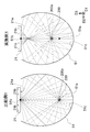
- FIG. 7 is a drawing schematically showing reverse ray tracing diagrams of Comparative Example 1 and Example 1. This drawing schematically shows the result of ray tracing of light emitted from a point light source when a virtual point light source is arranged at the position of the center 200a of the optical fiber 200 in each light irradiation device. Is. By tracing this drawing in reverse, a light beam that can irradiate the center 200a of the optical fiber 200 is determined. In FIG. 7, only light that is emitted from a virtual point light source and reaches the light source 21 after being reflected by the reflecting surface 51 c of the reflector 51 is illustrated.
- the optical fiber 200 is disposed at the position of the first focal point 51a, and the light emitting surface 21a of the light source 21 is disposed at the position of the second focal point 51b.
- the light emitted from the position of the second focal point 51b travels toward the optical fiber 200 after being reflected by the reflecting surface 51c.
- the light source 21 is composed of LED elements and emits light in a planar shape.
- the light emitting surface 21a has an area extending away from the second focal point 51b in the surface direction, that is, the end region 21b in the D2 direction, in addition to the region coinciding with the second focal point 51b.
- the light emitted from the end region 21 b and reflected by the reflecting surface 51 c of the reflector 51 does not reach the optical fiber 200 effectively.
- the optical fiber 200 when the optical fiber 200 is disposed at a position decentered from the first focal point 51a toward the light source 21 as in the first embodiment, the light emitted from the end region 21b of the light emitting surface 21a is reflected on the reflecting surface 51c. It is possible to proceed to the optical fiber 200 via That is, when the position of the optical fiber 200 is shifted from the first focal point 51a, a part of the light emitted from the position of the second focal point 51b on the light emitting surface 21a becomes difficult to reach the optical fiber 200, while on the light emitting surface 21a. The light emitted from the region (end region 21b) away from the second focal point 51b is irradiated on the optical fiber 200 after being reflected by the reflecting surface 51c.
- FIG. 8 is a graph showing the relationship between the amount of eccentricity of the optical fiber 200 from the first focal point 51a of the reflector 51 and the amount of light applied to the optical fiber 200.
- the horizontal axis indicates the value of the eccentricity d1 between the first focal point 51a of the reflector 51 and the center 200a of the optical fiber 200.
- the case where the amount of eccentricity is negative ( ⁇ ) means that the optical fiber 200 is eccentric in the direction approaching the light source 21, and the case where the amount of eccentricity is positive (+). This means that the optical fiber 200 is decentered in the direction away from the light source 21.
- the case where the amount of eccentricity is 0 means that the position of the optical fiber 200 coincides with the position of the first focal point 51a of the reflecting surface 51c of the reflector 51. This is the light irradiation of the first comparative example. Corresponds to the device.
- the position of the optical fiber 200 when the position of the optical fiber 200 is decentered from the first focus 51a toward the light source 21 (corresponding to the first embodiment), the position of the optical fiber 200 matches the position of the first focus 51a. It can be seen that the amount of irradiation light is improved as compared with the case. On the other hand, when the position of the optical fiber 200 is decentered from the first focus 51a to the side opposite to the light source 21, the amount of irradiation light is larger than when the position of the optical fiber 200 matches the position of the first focus 51a. It turns out that falls.
- the amount of the light beam that has been irradiated to the optical fiber 200 is larger than the light beam that is no longer irradiated to the optical fiber 200. It is thought that the amount of irradiation light has improved.
- the light emitted from the position of the second focal point 51b becomes difficult to reach the optical fiber 200 and the second focal point.
- the light emitted from the end region 21b away from 51b also reduces the amount of light flux that is applied to the optical fiber 200. This is because the optical fiber 200 as an irradiation target approaches the reflecting surface 51c of the reflector 51 and is at a position far from the light source 21, and as a result, the divergence angle for the light emitted from the light source 21 to reach the optical fiber 200. This is considered to be because the number of light beams reaching the optical fiber 200 is reduced.
- FIG. 9 is a graph showing the relationship between the amount of eccentricity of the light source 21 from the second focal point 51 b of the reflector 51 and the amount of light applied to the optical fiber 200.
- the horizontal axis indicates the value of the amount of eccentricity d ⁇ b> 2 between the second focal point 51 b of the reflector 51 and the light source 21.
- the vertical axis represents the relative value of the amount of light applied to the optical fiber 200, and corresponds to the ratio to the amount of light applied to the optical fiber 200 in the configuration of the first embodiment shown in FIG.
- the case where the amount of eccentricity is negative ( ⁇ ) means that the light source 21 is eccentric in the direction away from the first focal point 51a, and the case where the amount of eccentricity is positive (+). Means that the light source 21 is decentered in the direction of approaching the first focal point 51a. Moreover, the case where the amount of eccentricity is 0 means that the position of the light source 21 coincides with the position of the second focal point 51b of the reflecting surface 51c of the reflector 51. This is the light irradiation apparatus of the first embodiment.
- the amount of decrease in the amount of irradiation light by shifting the position of the light source 21 from the second focus 51 b to the side opposite to the first focus 51 a is the same as the position of the optical fiber 200.
- the amount of irradiation light is smaller than the amount of increase by shifting from the focal point 51a to the light source 21 side.
- the amount of light applied to the optical fiber 200 increases, and in addition, the position of the light source 21 is changed from the second focus 51b to the first focus 51a. It can be seen that the amount of light applied to the optical fiber 200 further increases by shifting to the side.
- the position of the light source 21 is shifted from the second focal point 51b to the opposite side of the first focal point 51a, the amount of light applied to the optical fiber 200 is reduced as compared with the configuration of the first embodiment, but the comparative example This is an improvement over the first configuration.
- the light source 21 is also arranged at a position decentered from the second focal point 51b, but the light source 21 may be arranged at the position of the second focal point 51b. .
- the first distance d1 between the center 51a of the reflecting surface 51c of the reflector 51 and the center 61a of the insertion path 61 is preferably not less than the radius of the optical fiber 200. More preferably, the diameter is equal to or larger than the diameter of the optical fiber 200. In this case, the center 51 a of the reflecting surface 51 c of the reflector 51 can be positioned outside the optical fiber 200.
- the reflecting surface 51c may be formed of an elliptical arc-shaped curved surface, or a substantially elliptical arc-shaped curved surface may be formed by combining a plurality of planes.
- the light source 21 is composed of a plurality of LED elements, but may be composed of a plurality of LD (laser diode) elements.
- the light irradiation device 1 may include a plurality of light sources 21.
- each light source 21 may be disposed at a position on the opposite side of the insertion path 61, that is, the optical fiber 200 with respect to the opening 53 (see FIG. 5) of the reflector 51.
- each light source 21 is arranged at a position opposite to the reflector 51 with respect to the insertion path 61, that is, the optical fiber 200.
- the insertion path 61 when viewed in the direction D1 is described as being circular, but the shape of the insertion path 61 is arbitrary.
- the insertion path 61 when viewed in the direction D1 may be, for example, a polygonal shape or an elliptical shape.
- the insertion path 61 is described as being configured by the inner portion of the insertion portion 6 made of a cylindrical body.
- the light irradiation device 1 does not include the insertion portion 6 itself, and the inner side of the reflector 51.
- the insertion path 61 may be configured by the partial space.
- the “center of the insertion path 61” means a passing position of the optical fiber 200 in a state in which the optical fiber 200 is inserted, and in a state before the optical fiber 200 is inserted, It means the position where the fiber 200 is to be passed. In the latter case, the center position of the insertion path 61 can be the center position of the inscribed circle of the insertion path 61.
- the optical fiber 200 is inserted with the center 200 a of the optical fiber 200 positioned at the center 61 a of the insertion path 61.
- the optical fiber 200 may be inserted with the center 200 a thereof shifted from the center 61 a of the insertion path 61.
- the center 61a of the insertion path 61 is not necessarily decentered from the first focus 51a.
- the light irradiation device 1 has been described as irradiating the optical fiber 200 to be conveyed with light.
- the present invention is not limited to such a use mode.
- the aspect of irradiating light from the light source 21 to the fixed optical fiber 200 during light irradiation is also within the scope of the present invention.
- the light irradiation device 1 is described as irradiating the optical fiber 200 with light.
- the wire as an object to be irradiated with light is not limited to an optical fiber, and may be, for example, a fiber.
- the fiber By irradiating the fiber with ultraviolet light using the light irradiation device 1, it can be used for surface modification of the fiber.
Landscapes
- Physics & Mathematics (AREA)
- Life Sciences & Earth Sciences (AREA)
- Chemical & Material Sciences (AREA)
- Chemical Kinetics & Catalysis (AREA)
- Electromagnetism (AREA)
- General Life Sciences & Earth Sciences (AREA)
- Optics & Photonics (AREA)
- Engineering & Computer Science (AREA)
- General Physics & Mathematics (AREA)
- General Chemical & Material Sciences (AREA)
- Geochemistry & Mineralogy (AREA)
- Materials Engineering (AREA)
- Organic Chemistry (AREA)
- Optical Fibers, Optical Fiber Cores, And Optical Fiber Bundles (AREA)
- Coating Apparatus (AREA)
- Surface Treatment Of Glass Fibres Or Filaments (AREA)
Applications Claiming Priority (2)
| Application Number | Priority Date | Filing Date | Title |
|---|---|---|---|
| JP2017118899A JP6815942B2 (ja) | 2017-06-16 | 2017-06-16 | 光照射装置、光照射方法 |
| JP2017-118899 | 2017-06-16 |
Publications (1)
| Publication Number | Publication Date |
|---|---|
| WO2018230697A1 true WO2018230697A1 (ja) | 2018-12-20 |
Family
ID=64660922
Family Applications (1)
| Application Number | Title | Priority Date | Filing Date |
|---|---|---|---|
| PCT/JP2018/022873 Ceased WO2018230697A1 (ja) | 2017-06-16 | 2018-06-15 | 光照射装置、光照射方法 |
Country Status (2)
| Country | Link |
|---|---|
| JP (1) | JP6815942B2 (2) |
| WO (1) | WO2018230697A1 (2) |
Citations (4)
| Publication number | Priority date | Publication date | Assignee | Title |
|---|---|---|---|---|
| JPH05254894A (ja) * | 1992-03-13 | 1993-10-05 | Furukawa Electric Co Ltd:The | 紫外線照射装置 |
| JP2004506932A (ja) * | 2000-06-22 | 2004-03-04 | フュージョン・ユーヴィー・システムズ・インコーポレイテッド | 光ファイバー表面を均一に照射するための楕円形反射器を備えるランプ構造及びその使用方法 |
| JP2013527554A (ja) * | 2009-12-23 | 2013-06-27 | フュージョン ユーブイ システムズ, インコーポレイテッド | 小型硬化用ランプ組立体用uvledを基礎としたランプ |
| JP2016534967A (ja) * | 2013-07-23 | 2016-11-10 | フォセオン テクノロジー, インコーポレイテッドPhoseon Technology, Inc. | 光ファイバー硬化のための組み合わされた楕円反射器 |
Family Cites Families (4)
| Publication number | Priority date | Publication date | Assignee | Title |
|---|---|---|---|---|
| JP4794778B2 (ja) * | 2001-09-14 | 2011-10-19 | 古河電気工業株式会社 | 光ファイバ被覆装置 |
| US8314408B2 (en) * | 2008-12-31 | 2012-11-20 | Draka Comteq, B.V. | UVLED apparatus for curing glass-fiber coatings |
| US8872137B2 (en) * | 2011-09-15 | 2014-10-28 | Phoseon Technology, Inc. | Dual elliptical reflector with a co-located foci for curing optical fibers |
| JP2016210668A (ja) * | 2015-04-28 | 2016-12-15 | Jsr株式会社 | 光ファイバ製造用紫外線照射装置 |
-
2017
- 2017-06-16 JP JP2017118899A patent/JP6815942B2/ja active Active
-
2018
- 2018-06-15 WO PCT/JP2018/022873 patent/WO2018230697A1/ja not_active Ceased
Patent Citations (4)
| Publication number | Priority date | Publication date | Assignee | Title |
|---|---|---|---|---|
| JPH05254894A (ja) * | 1992-03-13 | 1993-10-05 | Furukawa Electric Co Ltd:The | 紫外線照射装置 |
| JP2004506932A (ja) * | 2000-06-22 | 2004-03-04 | フュージョン・ユーヴィー・システムズ・インコーポレイテッド | 光ファイバー表面を均一に照射するための楕円形反射器を備えるランプ構造及びその使用方法 |
| JP2013527554A (ja) * | 2009-12-23 | 2013-06-27 | フュージョン ユーブイ システムズ, インコーポレイテッド | 小型硬化用ランプ組立体用uvledを基礎としたランプ |
| JP2016534967A (ja) * | 2013-07-23 | 2016-11-10 | フォセオン テクノロジー, インコーポレイテッドPhoseon Technology, Inc. | 光ファイバー硬化のための組み合わされた楕円反射器 |
Also Published As
| Publication number | Publication date |
|---|---|
| JP2019003107A (ja) | 2019-01-10 |
| JP6815942B2 (ja) | 2021-01-20 |
Similar Documents
| Publication | Publication Date | Title |
|---|---|---|
| WO2018230546A1 (ja) | 光照射装置、光照射方法 | |
| JP6275250B2 (ja) | 放射エネルギーの使用によって被覆を硬化させる装置、及び高アスペクト比基材上のポリマー被覆を硬化させる方法 | |
| JP2008216409A (ja) | 導光体及び2分岐線状光源装置 | |
| JP6326746B2 (ja) | 偏光光照射装置 | |
| JPH01309204A (ja) | 電磁波集中装置およびその製造方法 | |
| JP6878762B2 (ja) | 光照射装置及び光照射方法 | |
| CN106958747A (zh) | 光照射装置 | |
| CN108367976B (zh) | 光照射装置及光照射方法 | |
| WO2018230697A1 (ja) | 光照射装置、光照射方法 | |
| US10274138B2 (en) | Lighting device and lighting system | |
| EP3245464A1 (en) | Uv light curing systems and methods of designing and operating uv light curing systems | |
| JP6816413B2 (ja) | 光照射装置 | |
| JP6763450B2 (ja) | 光照射装置 | |
| JP6857334B2 (ja) | 光照射装置 | |
| JP6853943B2 (ja) | 光照射装置 | |
| CN102194645B (zh) | 照明单元及其应用 | |
| CN112955805B (zh) | 光学系统装置及双凸透镜 | |
| JP6614413B2 (ja) | 光源装置及びその製造方法 | |
| WO2018207501A1 (ja) | 光学素子および光学系装置 | |
| CN206320683U (zh) | 具有旋转变焦结构的变焦投射灯 | |
| JP2019003107A5 (2) | ||
| WO2018207380A1 (ja) | 光学素子および光学系装置 | |
| JP2015195141A (ja) | 照射装置 | |
| JP2010008672A (ja) | 光照射装置 | |
| JPH0843637A (ja) | 平行入射式の光分配構造 |
Legal Events
| Date | Code | Title | Description |
|---|---|---|---|
| 121 | Ep: the epo has been informed by wipo that ep was designated in this application |
Ref document number: 18817512 Country of ref document: EP Kind code of ref document: A1 |
|
| NENP | Non-entry into the national phase |
Ref country code: DE |
|
| 122 | Ep: pct application non-entry in european phase |
Ref document number: 18817512 Country of ref document: EP Kind code of ref document: A1 |