WO2018235157A1 - Moteur électrique, compresseur, climatiseur et procédé de fabrication d'un moteur électrique - Google Patents
Moteur électrique, compresseur, climatiseur et procédé de fabrication d'un moteur électrique Download PDFInfo
- Publication number
- WO2018235157A1 WO2018235157A1 PCT/JP2017/022658 JP2017022658W WO2018235157A1 WO 2018235157 A1 WO2018235157 A1 WO 2018235157A1 JP 2017022658 W JP2017022658 W JP 2017022658W WO 2018235157 A1 WO2018235157 A1 WO 2018235157A1
- Authority
- WO
- WIPO (PCT)
- Prior art keywords
- heat
- rotor
- base
- heat sink
- motor
- Prior art date
- Legal status (The legal status is an assumption and is not a legal conclusion. Google has not performed a legal analysis and makes no representation as to the accuracy of the status listed.)
- Ceased
Links
Images







Classifications
-
- H—ELECTRICITY
- H02—GENERATION; CONVERSION OR DISTRIBUTION OF ELECTRIC POWER
- H02K—DYNAMO-ELECTRIC MACHINES
- H02K5/00—Casings; Enclosures; Supports
- H02K5/04—Casings or enclosures characterised by the shape, form or construction thereof
- H02K5/08—Insulating casings
-
- H—ELECTRICITY
- H02—GENERATION; CONVERSION OR DISTRIBUTION OF ELECTRIC POWER
- H02K—DYNAMO-ELECTRIC MACHINES
- H02K15/00—Processes or apparatus specially adapted for manufacturing, assembling, maintaining or repairing of dynamo-electric machines
- H02K15/12—Impregnating, moulding insulation, heating or drying of windings, stators, rotors or machines
-
- H—ELECTRICITY
- H02—GENERATION; CONVERSION OR DISTRIBUTION OF ELECTRIC POWER
- H02K—DYNAMO-ELECTRIC MACHINES
- H02K15/00—Processes or apparatus specially adapted for manufacturing, assembling, maintaining or repairing of dynamo-electric machines
- H02K15/14—Casings; Enclosures; Supports
-
- H—ELECTRICITY
- H02—GENERATION; CONVERSION OR DISTRIBUTION OF ELECTRIC POWER
- H02K—DYNAMO-ELECTRIC MACHINES
- H02K5/00—Casings; Enclosures; Supports
- H02K5/04—Casings or enclosures characterised by the shape, form or construction thereof
- H02K5/18—Casings or enclosures characterised by the shape, form or construction thereof with ribs or fins for improving heat transfer
-
- H—ELECTRICITY
- H02—GENERATION; CONVERSION OR DISTRIBUTION OF ELECTRIC POWER
- H02K—DYNAMO-ELECTRIC MACHINES
- H02K9/00—Arrangements for cooling or ventilating
- H02K9/22—Arrangements for cooling or ventilating by solid heat conducting material embedded in, or arranged in contact with, the stator or rotor, e.g. heat bridges
- H02K9/227—Heat sinks
-
- F—MECHANICAL ENGINEERING; LIGHTING; HEATING; WEAPONS; BLASTING
- F04—POSITIVE - DISPLACEMENT MACHINES FOR LIQUIDS; PUMPS FOR LIQUIDS OR ELASTIC FLUIDS
- F04D—NON-POSITIVE-DISPLACEMENT PUMPS
- F04D25/00—Pumping installations or systems
- F04D25/02—Units comprising pumps and their driving means
- F04D25/08—Units comprising pumps and their driving means the working fluid being air, e.g. for ventilation
- F04D25/082—Units comprising pumps and their driving means the working fluid being air, e.g. for ventilation the unit having provision for cooling the motor
-
- F—MECHANICAL ENGINEERING; LIGHTING; HEATING; WEAPONS; BLASTING
- F24—HEATING; RANGES; VENTILATING
- F24F—AIR-CONDITIONING; AIR-HUMIDIFICATION; VENTILATION; USE OF AIR CURRENTS FOR SCREENING
- F24F1/00—Room units for air-conditioning, e.g. separate or self-contained units or units receiving primary air from a central station
- F24F1/0007—Indoor units, e.g. fan coil units
- F24F1/00073—Indoor units, e.g. fan coil units comprising a compressor in the indoor unit housing
-
- F—MECHANICAL ENGINEERING; LIGHTING; HEATING; WEAPONS; BLASTING
- F24—HEATING; RANGES; VENTILATING
- F24F—AIR-CONDITIONING; AIR-HUMIDIFICATION; VENTILATION; USE OF AIR CURRENTS FOR SCREENING
- F24F1/00—Room units for air-conditioning, e.g. separate or self-contained units or units receiving primary air from a central station
- F24F1/06—Separate outdoor units, e.g. outdoor unit to be linked to a separate room comprising a compressor and a heat exchanger
- F24F1/08—Compressors specially adapted for separate outdoor units
Definitions
- the present invention relates to a motor having a heat sink.
- a heat sink as a heat dissipating member is used to dissipate the heat of the motor to the outside.
- a motor provided with a U-shaped heat sink has been proposed (see, for example, Patent Document 1).
- An object of the present invention is to enhance the heat dissipation efficiency of a motor.
- the electric motor according to the present invention comprises a stator assembly, a rotor provided inside the stator assembly, and a heat sink fixed to the stator assembly and releasing heat of the stator assembly.
- the heat sink has a base portion and a heat dissipation portion integrally formed with the base portion.
- the heat radiation efficiency of the motor can be enhanced.
- FIG. 5 is a cross-sectional view showing a stator and a heat sink disposed in a mold.
- A is a top view which shows the other example of a heat sink roughly,
- (b) is a sectional view along line 9b-9b shown in (a).
- (A) is a plan view schematically showing the structure of the heat sink, and
- (b) is a cross-sectional view taken along the line 10b-10b shown in (a).
- FIG. 5 is a cross-sectional view showing a stator and a heat sink disposed in a mold.
- A) is a top view which shows the structure of a heat sink roughly,
- (b) is sectional drawing along line 12b-12b shown by (a).
- FIG. 5 is a cross-sectional view showing a stator and a heat sink disposed in a mold. It is a figure which shows roughly the structure of the air conditioner concerning Embodiment 4 of this invention.
- Embodiment 1 The motor 1 according to the first embodiment of the present invention will be described below.
- the z-axis direction (z-axis) is parallel to the axis A1 of the shaft 22 of the motor 1 (ie, the rotation axis of the rotor 2) ("the axial direction of the rotor 2 (Also referred to as “axial direction”)
- the x-axis direction (x-axis) indicates a direction orthogonal to the z-axis direction (z-axis)
- the y-axis direction indicates both the z-axis direction and the x-axis direction Indicates the direction orthogonal to
- FIG. 1 is a cross-sectional view schematically showing a structure of a motor 1 according to Embodiment 1 of the present invention.
- FIG. 2 is a front view schematically showing the structure of the motor 1.
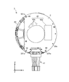
- FIG. 3 is a front view schematically showing the structure of the stator assembly 3. However, the stator assembly 3 shown in FIG. 3 is in a state before molding of the resin 6.
- the electric motor 1 (also referred to as a molded electric motor) has a rotor 2 (also referred to as a rotor assembly), a stator assembly 3 (also referred to as a molded stator), a heat sink 5 as a heat dissipation member, and bearings 7a and 7b. .
- the motor 1 further includes a bracket 8 and a waterproof rubber 9 for sealing the motor 1.
- the motor 1 is, for example, a permanent magnet synchronous motor, but is not limited thereto.
- the bearings 7 a and 7 b rotatably support both ends of the shaft 22 of the rotor 2.
- the rotor 2 has a rotor core 21 and a shaft 22.
- the rotor 2 is rotatable about the rotation axis (ie, the axis A1).
- the rotor 2 is rotatably provided inside the stator assembly 3 (specifically, the stator 30) via an air gap.
- the rotor 2 may further have permanent magnets for forming the magnetic poles of the rotor 2.
- the stator assembly 3 includes a stator 30, a printed circuit board 4, lead wires 41 connected to the printed circuit board 4, a drive circuit 42 fixed to the surface of the printed circuit board 4, and resin 6 (also referred to as mold resin). And.
- FIG. 4 is a front view schematically showing the structure of the stator 30.
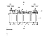
- FIG. 5 is a side view schematically showing the structure of the stator 30. As shown in FIG.
- the stator 30 has a stator core 31 in which a plurality of electromagnetic steel plates are stacked in the axial direction, a winding 32 (also referred to as a stator winding), and an insulator 33 as an insulating portion.
- a winding 32 also referred to as a stator winding
- an insulator 33 as an insulating portion.
- Each of the plurality of magnetic steel sheets is formed into a predetermined shape by a punching process, and fixed to each other by caulking, welding, adhesion or the like.
- the winding 32 is, for example, a magnet wire.
- a coil is formed by winding the winding 32 around the insulator 33 combined with the stator core 31.
- the winding 32 is electrically connected to the terminal 32a (winding terminal).
- the end of the winding 32 is hooked on the hook of the terminal 32a and is fixed to the terminal 32a by fusing or solder.
- the terminal 32 a is fixed to the insulator 33 and is electrically connected to the printed circuit board 4.
- the insulator 33 has at least one fixing portion 331 for fixing the printed circuit board 4.
- the insulator 33 is, for example, a thermoplastic resin such as PBT (polybutylene terephthalate).
- the insulator 33 electrically insulates the stator core 31 (for example, the teeth of the stator core 31).
- the insulator 33 is, for example, integrally formed with the stator core 31. However, the insulator 33 may be formed in advance, and the formed insulator 33 may be combined with the stator core 31.
- the printed circuit board 4 has positioning holes 43 (also simply referred to as “holes”) that engage with the fixing portions 331 (specifically, the protrusions 331 a) of the insulator 33.
- the fixing portion 331 of the insulator 33 has a protrusion 331 a and a support portion 331 b.
- the protrusions 331a are inserted into positioning holes 43 formed in the printed circuit board 4 (FIG. 3). Thereby, the printed circuit board 4 is fixed to the insulator 33.
- the support portion 331 b axially supports the printed circuit board 4 and positions the printed circuit board 4 in the axial direction.
- the printed circuit board 4 is integrated with the stator 30 by the resin 6 (FIG. 1).
- the drive circuit 42 controls the rotation of the rotor 2.
- the drive circuit 42 includes, for example, a drive element 42 a and a Hall IC (Integrated Circuit) 42 b.
- the drive element 42a is, for example, a power transistor.
- the drive element 42a is electrically connected to the winding 32, and supplies the winding 32 with a drive current based on the current supplied from the outside or the inside (for example, a battery) of the motor 1.
- the drive element 42 a controls the rotation of the rotor 2.
- the Hall IC 42 b detects the rotational position of the rotor 2 by detecting the magnetic field from the rotor 2.
- the resin 6 is, for example, a thermosetting resin such as BMC (bulk molding compound).
- BMC is suitable for insert molding to enable low pressure molding. Thereby, when shaping
- the resin 6 may be a thermoplastic resin such as PPS (polyphenylene sulfide). Since heat conductivity of PPS is improved compared to BMC, the heat of the stator assembly 3 is easily transmitted to the heat sink 5. Thereby, the heat dissipation of the electric motor 1 can be improved, and the temperature rise of the printed circuit board 4 and the winding 32 can be suppressed.
- PPS polyphenylene sulfide
- the heat sink 5 is formed of, for example, a metal material such as aluminum.
- the outer shape of the heat sink 5 (specifically, the planar shape on the xy plane) is circular.
- the heat sink 5 is integrated with the stator assembly 3 by the resin 6 by fitting a part of the heat sink 5 (a base 51 described later) with the resin 6.
- the heat sink 5 is fixed to the stator assembly 3 and dissipates the heat of the stator assembly 3 (for example, the heat generated from the stator 30 or the drive circuit 42) to the outside of the motor 1.
- a part of the heat sink 5 for example, the heat radiating portion 52 shown in FIG. 2 is exposed to the outside of the motor 1 (specifically, the resin 6). Thereby, the heat generated from the stator assembly 3 is released to the outside of the motor 1.
- the heat sink 5 may be in contact with the printed circuit board 4. When the heat sink 5 is in contact with the printed circuit board 4, the heat of the printed circuit board 4 can be efficiently dissipated to the outside of the motor 1.
- a heat dissipation assisting member formed of a material having high thermal conductivity may be disposed between the printed circuit board 4 and the heat sink 5. Thereby, the heat of the stator assembly 3 can be efficiently released to the outside of the motor 1.
- the heat radiation assisting member can be formed, for example, in a sheet shape or a block shape.
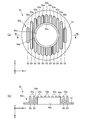
- FIG. 6 (a) is a plan view schematically showing an example of the heat sink 5
- FIG. 6 (b) is a cross-sectional view taken along the line 6b-6b shown in FIG. 6 (a).
- the heat sink 5 has a base portion 51 and a heat radiating portion 52 integrally formed with the base portion 51.
- the base portion 51 is an outer edge of the heat sink 5 and has a width in the radial direction of the heat sink 5 (also referred to as “radial direction of the rotor 2” or simply “radial direction”).
- the outer shape of the base 51 (specifically, the planar shape on the xy plane) is circular.
- the heat radiating portion 52 is formed inside the base portion 51 in the radial direction.
- the heat radiating portion 52 has a plurality of fins 53. Each fin 53 protrudes in the axial direction.
- the heat radiating portion 52 has at least one heat radiating surface 53a.
- the heat dissipation surface 53 a is an upper surface of each fin 53.
- FIG. 7 is a flowchart showing an example of a manufacturing process of the motor 1.
- the method of manufacturing the motor 1 includes the steps described below.
- step S1 the stator 30 is manufactured.
- stator iron core 31 is formed by laminating a plurality of electromagnetic steel plates in the axial direction.
- the insulator 33 formed in advance is attached to the stator core 31, and the winding 32 is wound around the stator core 31 and the insulator 33. Thereby, the stator 30 is obtained.
- the protrusion 331 a of the insulator 33 is inserted into the positioning hole 43 of the printed circuit board 4.
- a drive circuit 42 is fixed in advance to the surface of the printed circuit board 4.
- the lead wires 41 are also attached to the printed circuit board 4 in advance.
- the protrusion 331 a protruding from the positioning hole 43 may be fixed to the printed circuit board 4 by heat welding or ultrasonic welding or the like.
- FIG. 8 is a cross-sectional view showing the stator 30 and the heat sink 5 disposed in the mold 100.
- the stator 30 and the heat sink 5 are disposed in the mold 100.
- the stator 30 is disposed in the first mold 101 on the fixed side of the mold 100, and the heat sink 5 fabricated in advance is combined with the stator 30.
- the second mold 102 is combined with the first mold 101 such that the inner surface 102 a of the movable second mold 102 of the mold 100 contacts the base portion 51 of the heat sink 5.
- the second mold 102 is combined with the first mold 101 so that no gap is generated between the inner surface 102 a of the second mold 102 and the base 51.
- step S3 the resin 6 is molded. Specifically, the resin 6 is injected into the mold 100. Thus, the base portion 51 is fitted with the resin 6, and the heat sink 5 is integrated with the stator 30 and the printed circuit board 4 by the resin 6. Thereby, the stator assembly 3 is obtained.
- step S4 the rotor 2 is manufactured.
- the shaft 22 is inserted into an axial hole formed in the rotor core 21 to obtain the rotor 2.
- Permanent magnets forming the magnetic poles may be attached to the rotor core 21 in advance.
- step S5 the shaft 22 is inserted into the bearings 7a and 7b.
- step S1 to step S5 is not limited to the order shown in FIG.
- the steps from step S1 to step S3 and step S4 can be performed in parallel with each other.
- Step S4 may be performed prior to steps S1 to S3.
- step S6 the rotor 2 is inserted into the stator assembly 3 (specifically, the stator 30) together with the bearings 7a and 7b.
- step S7 the bracket 8 is fitted inside the resin 6, and the waterproof rubber 9 is fitted on the shaft 22.
- the motor 1 is assembled by the steps described above.
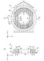
- FIG. 9 (a) is a plan view schematically showing another example of the heat sink 5 as the heat sink 5a
- FIG. 9 (b) is a cross section taken along line 9b-9b shown in FIG. 9 (a).
- the structure of the heat radiating portion 52 a is different from the structure of the heat radiating portion 52 of the heat sink 5.
- the other structure of the heat sink 5 a is the same as that of the heat sink 5.
- the heat sink 5 a is applicable to the motor 1 instead of the heat sink 5.
- the heat sink 5a has a base portion 51 and a heat radiating portion 52a.
- the heat radiating portion 52a has a plurality of fins 53, a heat radiating surface 54a (first heat radiating surface), a heat radiating surface 53a (second heat radiating surface), an outer circumferential surface 54b, and a hollow portion 54c.
- the hollow portion 54 c penetrates the base portion 51 and the heat radiating portion 52 in the axial direction.
- the hollow portion 54c extends in the circumferential direction and has a width in the axial direction. The axial length of the hollow portion 54c may be adjusted according to the position of the bearing 7b.
- the heat dissipation surface 54a is formed on the side opposite to the base portion 51 in the axial direction, and the circumferential direction of the heat sink 5 (hereinafter simply referred to as “circumferential direction”) about the rotation axis (that is, the axis A1) of the rotor 2 To extend).
- the heat dissipation surface 54a has a width in the radial direction.
- the heat sink 5 is fixed to the stator assembly 3, the heat radiation efficiency of the motor 1 can be enhanced.
- the inner surface 102a of the second mold 102 on the movable side of the mold 100 is in the manufacturing process of the motor 1 (specifically, step S2 in FIG. 7).
- the second mold 102 can be combined with the first mold 101 to contact the base 51 of the heat sink 5.
- the resin 6 passes through between the inner surface 102a of the second mold 102 and the base portion 51. It can prevent.
- the resin 6 can be prevented from entering the heat radiating portion 52 (for example, the fins 53).
- the heat dissipation efficiency of the motor 1 can be enhanced.
- the heat sink 5 can be integrated with the stator assembly 3 such that the bearing 7b is located inside the hollow portion 54c.
- the distance from the stator assembly 3 (for example, the printed circuit board 4 and the drive circuit 42) to the heat sink 5 is shortened, so the heat dissipation efficiency of the motor 1 can be enhanced.
- FIG. 10 (a) is a plan view schematically showing the structure of the heat sink 5b
- FIG. 10 (b) is a cross-sectional view taken along line 10b-10b shown in FIG. 10 (a).
- the structure of the heat sink 5 b is different from the structure of the heat sink 5 in the motor 1 according to the first embodiment.
- the structure other than the heat sink 5 b is the same as the structure of the motor 1 according to the first embodiment.
- the heat sink 5 b has a base portion 51 and a heat radiating portion 52 b integrally formed with the base portion 51.
- the heat radiating portion 52 b includes a plurality of fins 53, a heat radiating surface 54 a (first heat radiating surface), a heat radiating surface 53 a (second heat radiating surface), and an outer circumferential surface 54 b as a heat radiating wall (first wall).
- a hollow portion 54c and a heat radiation wall 54d (second wall) are provided. The hollow portion 54c penetrates the base portion 51 and the heat radiating portion 52b in the axial direction.
- the heat dissipation surface 54a is formed on the opposite side to the base 51 in the axial direction, and extends in the circumferential direction.
- the heat sink 5b further has at least one recess 55 for positioning the heat sink 5b.
- the recess 55 is formed in the heat radiation surface 54a.
- the position of the recess 55 may be other than the heat dissipation surface 54a.
- the recess 55 is, for example, a notch or a hole.
- the heat dissipation surface 53 a is an upper surface of each fin 53.
- the heat radiation surface 53a is formed on the outer side in the axial direction and the radial direction than the heat radiation surface 54a.
- the outer circumferential surface 54b forms an outer surface of the heat radiating portion 52b in the circumferential direction, and is axially long.
- the heat dissipation wall 54d is formed between the heat dissipation surface 54a and the heat dissipation surface 53a.
- the heat dissipation wall 54 d extends in the circumferential direction and has a width in the axial direction.
- FIG. 11 is a cross-sectional view showing the stator 30 and the heat sink 5 b disposed in the mold 100.
- the process in step S2 shown in FIG. 7 is different from the method of manufacturing the motor 1 according to the first embodiment.
- the stator 30 is disposed in the first mold 101 on the fixed side of the mold 100, and the heat sink 5b manufactured in advance is combined with the stator 30.
- the second mold 102 is formed so that the inner surface 102a of the second mold 102 on the movable side of the mold 100 contacts the base 51, the outer peripheral surface 54b, the heat dissipation surface 54a, and the heat dissipation wall 54d. Combine with the type 101 of.
- the second mold 102 is used as a first mold so that no gap is generated between the inner surface 102a of the second mold 102, the base portion 51, the outer peripheral surface 54b, the heat dissipation surface 54a, and the heat dissipation wall 54d. Combine with 101.
- step S2 In the method of manufacturing a motor according to the second embodiment, the processes other than step S2 are the same as the method of manufacturing the motor 1 according to the first embodiment.
- the motor according to the second embodiment has the same effect as the effect of the motor 1 according to the first embodiment (including the effect of the modification).
- the method of manufacturing the motor according to the second embodiment has the same effect as the method of manufacturing the motor 1 according to the first embodiment.
- the inner surface 102a of the second mold 102 on the movable side of the mold 100 is the base portion 51.
- the second mold 102 can be combined with the first mold 101 to be in contact with the outer peripheral surface 54b, the heat dissipation surface 54a, and the heat dissipation wall 54d.
- the resin 6 is injected into the mold 100 (specifically, step S3 in FIG. 7)
- the resin 6 passes through between the inner surface 102a of the second mold 102 and the base portion 51. It can prevent.
- the thermal radiation part 52b for example, fin 53
- the resin 6 flowing into the hollow portion 54c can be prevented from passing between the inner surface 102a and the heat dissipation surface 54a. Even when the resin 6 passes between the inner surface 102a and the heat radiation surface 54a, the heat radiation portion 52b (for example, the fins 53) is covered with the resin 6 because the inner surface 102a is in contact with the heat radiation wall 54d. It can prevent.
- the heat radiating portion 52b specifically, the plurality of fins 53 is exposed to the outside of the motor according to the second embodiment, so that the heat radiation efficiency of the motor can be enhanced.
- FIG. 12 (a) is a plan view schematically showing the structure of the heat sink 5c
- FIG. 12 (b) is a cross-sectional view taken along line 12b-12b shown in FIG. 12 (a).
- the structure of the heat sink 5c is different from the structure of the heat sink 5 in the motor 1 according to the first embodiment.
- the structure other than the heat sink 5c is the same as the structure of the motor 1 according to the first embodiment.
- the structure of the base 51a of the heat sink 5c is different from that of the base 51 of the heat sink 5b.
- the heat sink 5c has a base portion 51a and a heat dissipation portion 52b integrally formed with the base portion 51a.
- the base 51 a has at least one protrusion 56 and a flange 57.
- the protrusion 56 has a base surface 56 a (first base surface) which is an upper surface of the protrusion 56.
- the projecting portion 56 protrudes outward in the radial direction from the flange portion 57. Therefore, the base surface 56a protrudes outward in the radial direction.
- four protrusions 56 are formed on the heat sink 5c.
- the flange portion 57 has a base surface 57a (second base surface) and a step 57b (also referred to as a base wall) long in the axial direction.
- the base surface 57a is formed on the outer side ( ⁇ z side) in the axial direction than the base surface 56a, and is formed on the inner side in the radial direction than the base surface 56a. That is, the base surface 57a is a surface located between the base surface 56a and the heat dissipation surface 53a.
- the base surface 57a extends in the circumferential direction and protrudes in the radial direction. That is, the base surface 57a has a width in the radial direction.
- the step 57 b is formed between the base surface 56 a and the base surface 57 a.
- the step 57 b extends in the circumferential direction.
- the step 57 b has a width in the axial direction.
- FIG. 13 is a cross-sectional view showing the stator 30 and the heat sink 5c disposed in the mold 100. As shown in FIG. In the method of manufacturing the motor according to the third embodiment, the processes in steps S2 and S3 shown in FIG. 7 are different from the method of manufacturing the motor 1 according to the first embodiment.
- step S2 the stator 30 is disposed in the first mold 101 on the fixed side of the mold 100, and the heat sink 5c manufactured in advance is combined with the stator 30.
- the second mold 102 is formed so that the inner surface 102a of the movable second mold 102 on the movable side contacts the base surface 57a, the outer peripheral surface 54b, the heat dissipation surface 54a, and the heat dissipation wall 54d. Combine with the type 101 of.
- the second mold 102 is used as a first mold so that no gap is generated between the inner surface 102a of the second mold 102, the base surface 57a, the outer peripheral surface 54b, the heat dissipation surface 54a, and the heat dissipation wall 54d. Combine with 101. A gap is provided between the inner surface 102a and a part of the base 51a (specifically, the base surface 56a).
- step S3 the resin 6 is molded. Specifically, the resin 6 is injected into the mold 100. More specifically, the resin 6 is injected into the mold 100 so that the resin 6 enters between the inner surface 102 a and a part of the base 51 a (specifically, the base surface 56 a of the projection 56). Do. Furthermore, the resin 6 is injected into the mold 100 so that the protrusion 56 is covered with the resin 6. Thereby, a part of the base portion 51a (specifically, the base surface 56a of the projecting portion 56) is engaged with the resin 6, and the heat sink 5 is integrated with the stator 30 and the printed circuit board 4 by the resin 6. . Furthermore, the protrusion 56 is covered with the resin 6. Thereby, the stator assembly 3 is obtained.
- the manufacturing method of the motor according to the third embodiment is the same as the manufacturing method of the motor 1 according to the first embodiment except for steps S2 and S3.
- the motor according to the third embodiment has the same effects as the effects of the motor 1 according to the first embodiment (including the effects of the modification) and the motor according to the second embodiment.
- the method of manufacturing the motor according to the third embodiment has the same effect as the method of manufacturing the motor 1 according to the first embodiment and the method of manufacturing the motor according to the second embodiment.
- the heat sink 5 c can be prevented from rotating with respect to the resin 6. In other words, the displacement of the heat sink 5 c in the circumferential direction with respect to the resin 6 can be prevented.
- the resin 6 is filled between the inner surface 102a of the mold 100 and the projection 56 (specifically, the base surface 56a). Deviation of the heat sink 5c in the direction can be prevented.
- the heat sink 5c can be integrated with the stator assembly 3 without using fixing parts such as screws. Therefore, the number of parts of the motor according to the third embodiment and the number of manufacturing steps of the motor can be reduced, and the cost of the motor can be reduced.
- the projecting portion 56 in the base portion 51a, a part of the base portion 51a is made of resin 6 without forming a groove in the mold 100 (specifically, the second mold 102). It can be covered. Therefore, the manufacturing cost of the mold 100 can be reduced. Furthermore, since the projection 56 is formed on the base 51a, the portion covered with the resin 6 can be obtained, and the ratio of the surface area of the heat radiating portion 52b in the heat sink 5c can be increased. Thereby, the heat dissipation efficiency in the motor can be enhanced.
- FIG. 14 is a diagram schematically showing a configuration of the air conditioner 10 according to Embodiment 4 of the present invention.
- An air conditioner 10 for example, a refrigeration air conditioner
- An air conditioner 10 includes an indoor unit 11 as a fan (first fan), a refrigerant pipe 12, and a fan connected to the indoor unit 11 by a refrigerant pipe 12. And an outdoor unit 13 as a (second blower).
- the indoor unit 11 has a motor 11a (for example, the motor 1 according to the first embodiment), a blower 11b for blowing air by being driven by the motor 11a, and a housing 11c covering the motor 11a and the blower 11b.
- the blower 11b has, for example, a blade driven by the motor 11a.
- the outdoor unit 13 has a motor 13a (for example, the motor 1 according to the first embodiment), a blower 13b, a compressor 14, and a heat exchanger (not shown).
- the blower 13 b blows by being driven by the motor 13 a.
- the blower 13 b has, for example, a blade driven by the motor 13 a.
- the compressor 14 includes an electric motor 14a (for example, the electric motor 1 according to the first embodiment), a compression mechanism 14b (for example, a refrigerant circuit) driven by the electric motor 14a, and a housing 14c covering the electric motor 14a and the compression mechanism 14b.
- an electric motor 14a for example, the electric motor 1 according to the first embodiment
- a compression mechanism 14b for example, a refrigerant circuit driven by the electric motor 14a
- a housing 14c covering the electric motor 14a and the compression mechanism 14b.
- At least one of the indoor unit 11 and the outdoor unit 13 has the motor (including the modification) described in the first to third embodiments.
- the electric motors described in the first to third embodiments are applied to at least one of the electric motors 11a and 13a as a drive source of the blower unit.
- the motor 14a of the compressor 14 the motor (including the modification) described in the first to third embodiments may be used.
- the air conditioner 10 can perform, for example, an operation such as a cooling operation in which cold air is blown from the indoor unit 11 or a heating operation in which warm air is blown.
- the motor 11a is a drive source for driving the blower 11b.
- the blower 11b can blow the adjusted air.
- the motor (including the modification) described in the first to third embodiments is applied to at least one of the motors 11a and 13a.
- the same effect as the effect described in 3 can be obtained.
- failure of the air conditioner 10 resulting from heat generation of the motor can be prevented.
- the cost of the air conditioner 10 can be reduced by using the electric motor described in the first to third embodiments in the air conditioner 10.
- the motor according to the first to third embodiments (including the modification) as a drive source of the fan (for example, the indoor unit 11), the same effect as the first to third embodiments can be obtained. be able to. Thereby, the failure of the blower caused by the heat generation of the motor can be prevented.
- the motor described in the first to third embodiments can be mounted on an apparatus having a drive source, such as a ventilation fan, a home appliance, or a machine tool, in addition to the air conditioner 10.
- a drive source such as a ventilation fan, a home appliance, or a machine tool, in addition to the air conditioner 10.
Landscapes
- Engineering & Computer Science (AREA)
- Power Engineering (AREA)
- Manufacturing & Machinery (AREA)
- Physics & Mathematics (AREA)
- Thermal Sciences (AREA)
- Motor Or Generator Cooling System (AREA)
- Manufacture Of Motors, Generators (AREA)
- Motor Or Generator Frames (AREA)
Abstract
L'invention concerne un moteur électrique (1) comprenant un ensemble stator (3), un rotor (2) disposé à l'intérieur de l'ensemble stator (3), et un dissipateur thermique (5) servant à dissiper la chaleur de l'ensemble stator (3). Le dissipateur thermique (5) comprend une partie de base (51), et des parties de dissipation de chaleur (52) intégrées à la partie de base (51).
Priority Applications (4)
| Application Number | Priority Date | Filing Date | Title |
|---|---|---|---|
| JP2019524743A JP7093347B2 (ja) | 2017-06-20 | 2017-06-20 | 電動機、圧縮機、及び空気調和機、並びに電動機の製造方法 |
| US16/605,686 US11381137B2 (en) | 2017-06-20 | 2017-06-20 | Electric motor, compressor, air conditioner, and method for manufacturing electric motor |
| CN201780090977.9A CN110741540B (zh) | 2017-06-20 | 2017-06-20 | 电动机、压缩机、空气调节机及电动机的制造方法 |
| PCT/JP2017/022658 WO2018235157A1 (fr) | 2017-06-20 | 2017-06-20 | Moteur électrique, compresseur, climatiseur et procédé de fabrication d'un moteur électrique |
Applications Claiming Priority (1)
| Application Number | Priority Date | Filing Date | Title |
|---|---|---|---|
| PCT/JP2017/022658 WO2018235157A1 (fr) | 2017-06-20 | 2017-06-20 | Moteur électrique, compresseur, climatiseur et procédé de fabrication d'un moteur électrique |
Publications (1)
| Publication Number | Publication Date |
|---|---|
| WO2018235157A1 true WO2018235157A1 (fr) | 2018-12-27 |
Family
ID=64735577
Family Applications (1)
| Application Number | Title | Priority Date | Filing Date |
|---|---|---|---|
| PCT/JP2017/022658 Ceased WO2018235157A1 (fr) | 2017-06-20 | 2017-06-20 | Moteur électrique, compresseur, climatiseur et procédé de fabrication d'un moteur électrique |
Country Status (4)
| Country | Link |
|---|---|
| US (1) | US11381137B2 (fr) |
| JP (1) | JP7093347B2 (fr) |
| CN (1) | CN110741540B (fr) |
| WO (1) | WO2018235157A1 (fr) |
Cited By (1)
| Publication number | Priority date | Publication date | Assignee | Title |
|---|---|---|---|---|
| JPWO2023148949A1 (fr) * | 2022-02-07 | 2023-08-10 |
Families Citing this family (1)
| Publication number | Priority date | Publication date | Assignee | Title |
|---|---|---|---|---|
| SE542616C2 (en) * | 2018-09-27 | 2020-06-16 | Leine & Linde Ab | Rotary encoder and method for manufacturing a rotary encoder |
Citations (8)
| Publication number | Priority date | Publication date | Assignee | Title |
|---|---|---|---|---|
| JPH09205758A (ja) * | 1995-11-24 | 1997-08-05 | Toshiba Corp | 車両用全閉形主電動機 |
| JPH09252563A (ja) * | 1996-03-14 | 1997-09-22 | Toshiba Corp | 制御装置一体型モータ |
| JP2002027708A (ja) * | 2000-07-07 | 2002-01-25 | Railway Technical Res Inst | 全閉形駆動電動機 |
| JP2007267568A (ja) * | 2006-03-30 | 2007-10-11 | Mitsubishi Electric Corp | モールド電動機及び空気調和機 |
| WO2010029623A1 (fr) * | 2008-09-11 | 2010-03-18 | 三菱電機株式会社 | Treuil pour ascenseur |
| US20100126703A1 (en) * | 2008-09-16 | 2010-05-27 | Joy Ride Tech. Co., Ltd. | Motor device with heat dissipating capability |
| JP2010178463A (ja) * | 2009-01-28 | 2010-08-12 | Nidec Shibaura Corp | モータ及びその製造方法 |
| JP2012092747A (ja) * | 2010-10-27 | 2012-05-17 | Mitsubishi Heavy Ind Ltd | インバータ一体型電動圧縮機 |
Family Cites Families (17)
| Publication number | Priority date | Publication date | Assignee | Title |
|---|---|---|---|---|
| JP2720623B2 (ja) * | 1991-04-12 | 1998-03-04 | 三菱電機株式会社 | モールドモータ |
| JPH0898441A (ja) * | 1994-09-20 | 1996-04-12 | Fujitsu General Ltd | モールドモータ |
| JP3536394B2 (ja) * | 1994-12-22 | 2004-06-07 | 日本電産シバウラ株式会社 | モールドモータの製造方法 |
| JP3509288B2 (ja) | 1995-04-25 | 2004-03-22 | 日本電産シバウラ株式会社 | ブラシレスdcモータ |
| US5789833A (en) | 1995-11-24 | 1998-08-04 | Kabushiki Kaisha Toshiba | Totally-enclosed traction motor for electric railcar |
| US6774514B2 (en) * | 2000-02-25 | 2004-08-10 | Kabushiki Kaisha Toshiba | Totally enclosed type driving electric motor |
| JP2001327152A (ja) | 2000-05-12 | 2001-11-22 | Yaskawa Electric Corp | リニアモータ |
| JP2005094841A (ja) * | 2003-09-12 | 2005-04-07 | Matsushita Electric Ind Co Ltd | モールド電動機 |
| JP4881280B2 (ja) * | 2007-11-14 | 2012-02-22 | 住友建機株式会社 | 旋回制御装置 |
| JP5186899B2 (ja) * | 2007-11-28 | 2013-04-24 | パナソニック株式会社 | ブラシレスモータ |
| JP5264989B2 (ja) * | 2008-04-03 | 2013-08-14 | ウェンヤン ジャン | ブラシレス直流モーターおよびその放熱装置 |
| JP4806461B2 (ja) * | 2008-09-26 | 2011-11-02 | 三洋電機株式会社 | 電動モータ及び電動車輌 |
| JP2010279207A (ja) * | 2009-05-29 | 2010-12-09 | Sanyo Electric Co Ltd | モールドモータ、電動車両及びモールドモータの製造方法 |
| JP4894903B2 (ja) * | 2009-10-26 | 2012-03-14 | パナソニック株式会社 | モールド電動機 |
| JP2012174734A (ja) | 2011-02-17 | 2012-09-10 | Toyota Motor Corp | ヒートシンク及び当該ヒートシンクを備えた半導体パッケージ |
| JP2017169348A (ja) * | 2016-03-16 | 2017-09-21 | ミネベアミツミ株式会社 | モータ |
| US10840771B2 (en) * | 2016-09-28 | 2020-11-17 | Mitsubishi Electric Corporation | Motor, blower, air conditioner, and method of producing motor |
-
2017
- 2017-06-20 WO PCT/JP2017/022658 patent/WO2018235157A1/fr not_active Ceased
- 2017-06-20 US US16/605,686 patent/US11381137B2/en active Active
- 2017-06-20 JP JP2019524743A patent/JP7093347B2/ja not_active Expired - Fee Related
- 2017-06-20 CN CN201780090977.9A patent/CN110741540B/zh active Active
Patent Citations (8)
| Publication number | Priority date | Publication date | Assignee | Title |
|---|---|---|---|---|
| JPH09205758A (ja) * | 1995-11-24 | 1997-08-05 | Toshiba Corp | 車両用全閉形主電動機 |
| JPH09252563A (ja) * | 1996-03-14 | 1997-09-22 | Toshiba Corp | 制御装置一体型モータ |
| JP2002027708A (ja) * | 2000-07-07 | 2002-01-25 | Railway Technical Res Inst | 全閉形駆動電動機 |
| JP2007267568A (ja) * | 2006-03-30 | 2007-10-11 | Mitsubishi Electric Corp | モールド電動機及び空気調和機 |
| WO2010029623A1 (fr) * | 2008-09-11 | 2010-03-18 | 三菱電機株式会社 | Treuil pour ascenseur |
| US20100126703A1 (en) * | 2008-09-16 | 2010-05-27 | Joy Ride Tech. Co., Ltd. | Motor device with heat dissipating capability |
| JP2010178463A (ja) * | 2009-01-28 | 2010-08-12 | Nidec Shibaura Corp | モータ及びその製造方法 |
| JP2012092747A (ja) * | 2010-10-27 | 2012-05-17 | Mitsubishi Heavy Ind Ltd | インバータ一体型電動圧縮機 |
Cited By (2)
| Publication number | Priority date | Publication date | Assignee | Title |
|---|---|---|---|---|
| JPWO2023148949A1 (fr) * | 2022-02-07 | 2023-08-10 | ||
| WO2023148949A1 (fr) * | 2022-02-07 | 2023-08-10 | 三菱電機株式会社 | Moteur électrique et climatiseur |
Also Published As
| Publication number | Publication date |
|---|---|
| CN110741540B (zh) | 2022-01-18 |
| JP7093347B2 (ja) | 2022-06-29 |
| JPWO2018235157A1 (ja) | 2019-11-07 |
| CN110741540A (zh) | 2020-01-31 |
| US11381137B2 (en) | 2022-07-05 |
| US20200119621A1 (en) | 2020-04-16 |
Similar Documents
| Publication | Publication Date | Title |
|---|---|---|
| JP6664505B2 (ja) | 電動機、送風機、及び空気調和機、並びに電動機の製造方法 | |
| JP7042968B2 (ja) | 電動機、送風機、空気調和装置および電動機の製造方法 | |
| JP2023054248A (ja) | 回転子、電動機、送風機、空気調和装置、及び回転子の製造方法 | |
| JP6895996B2 (ja) | 電動機及び空気調和機、並びに電動機の製造方法 | |
| JP7093347B2 (ja) | 電動機、圧縮機、及び空気調和機、並びに電動機の製造方法 | |
| WO2022249307A1 (fr) | Moteur électrique et climatiseur | |
| US11996754B2 (en) | Motor, fan, air conditioner, and manufacturing method of motor | |
| JP7183401B2 (ja) | モータ、送風機、空気調和装置およびモータの製造方法 | |
| WO2023148949A1 (fr) | Moteur électrique et climatiseur | |
| WO2022180708A1 (fr) | Stator, moteur électrique et climatiseur | |
| WO2020026403A1 (fr) | Rotor, moteur, ventilateur, climatiseur et procédé de fabrication de rotor | |
| WO2024121879A1 (fr) | Moteur électrique et climatiseur | |
| WO2023233609A1 (fr) | Moteur électrique et climatiseur |
Legal Events
| Date | Code | Title | Description |
|---|---|---|---|
| 121 | Ep: the epo has been informed by wipo that ep was designated in this application |
Ref document number: 17914511 Country of ref document: EP Kind code of ref document: A1 |
|
| ENP | Entry into the national phase |
Ref document number: 2019524743 Country of ref document: JP Kind code of ref document: A |
|
| NENP | Non-entry into the national phase |
Ref country code: DE |
|
| 122 | Ep: pct application non-entry in european phase |
Ref document number: 17914511 Country of ref document: EP Kind code of ref document: A1 |