WO2018235221A1 - Soufflante de production d'air électrique, aspirateur électrique, et sèche-mains - Google Patents
Soufflante de production d'air électrique, aspirateur électrique, et sèche-mains Download PDFInfo
- Publication number
- WO2018235221A1 WO2018235221A1 PCT/JP2017/022989 JP2017022989W WO2018235221A1 WO 2018235221 A1 WO2018235221 A1 WO 2018235221A1 JP 2017022989 W JP2017022989 W JP 2017022989W WO 2018235221 A1 WO2018235221 A1 WO 2018235221A1
- Authority
- WO
- WIPO (PCT)
- Prior art keywords
- electric blower
- air
- motor
- path
- permanent magnet
- Prior art date
- Legal status (The legal status is an assumption and is not a legal conclusion. Google has not performed a legal analysis and makes no representation as to the accuracy of the status listed.)
- Ceased
Links
Images











Classifications
-
- F—MECHANICAL ENGINEERING; LIGHTING; HEATING; WEAPONS; BLASTING
- F04—POSITIVE - DISPLACEMENT MACHINES FOR LIQUIDS; PUMPS FOR LIQUIDS OR ELASTIC FLUIDS
- F04D—NON-POSITIVE-DISPLACEMENT PUMPS
- F04D29/00—Details, component parts, or accessories
- F04D29/26—Rotors specially for elastic fluids
- F04D29/28—Rotors specially for elastic fluids for centrifugal or helico-centrifugal pumps for radial-flow or helico-centrifugal pumps
- F04D29/281—Rotors specially for elastic fluids for centrifugal or helico-centrifugal pumps for radial-flow or helico-centrifugal pumps for fans or blowers
-
- F—MECHANICAL ENGINEERING; LIGHTING; HEATING; WEAPONS; BLASTING
- F04—POSITIVE - DISPLACEMENT MACHINES FOR LIQUIDS; PUMPS FOR LIQUIDS OR ELASTIC FLUIDS
- F04D—NON-POSITIVE-DISPLACEMENT PUMPS
- F04D17/00—Radial-flow pumps, e.g. centrifugal pumps; Helico-centrifugal pumps
- F04D17/06—Helico-centrifugal pumps
-
- F—MECHANICAL ENGINEERING; LIGHTING; HEATING; WEAPONS; BLASTING
- F04—POSITIVE - DISPLACEMENT MACHINES FOR LIQUIDS; PUMPS FOR LIQUIDS OR ELASTIC FLUIDS
- F04D—NON-POSITIVE-DISPLACEMENT PUMPS
- F04D17/00—Radial-flow pumps, e.g. centrifugal pumps; Helico-centrifugal pumps
- F04D17/08—Centrifugal pumps
- F04D17/16—Centrifugal pumps for displacing without appreciable compression
- F04D17/165—Axial entry and discharge
-
- F—MECHANICAL ENGINEERING; LIGHTING; HEATING; WEAPONS; BLASTING
- F04—POSITIVE - DISPLACEMENT MACHINES FOR LIQUIDS; PUMPS FOR LIQUIDS OR ELASTIC FLUIDS
- F04D—NON-POSITIVE-DISPLACEMENT PUMPS
- F04D25/00—Pumping installations or systems
- F04D25/02—Units comprising pumps and their driving means
- F04D25/06—Units comprising pumps and their driving means the pump being electrically driven
-
- F—MECHANICAL ENGINEERING; LIGHTING; HEATING; WEAPONS; BLASTING
- F04—POSITIVE - DISPLACEMENT MACHINES FOR LIQUIDS; PUMPS FOR LIQUIDS OR ELASTIC FLUIDS
- F04D—NON-POSITIVE-DISPLACEMENT PUMPS
- F04D25/00—Pumping installations or systems
- F04D25/02—Units comprising pumps and their driving means
- F04D25/08—Units comprising pumps and their driving means the working fluid being air, e.g. for ventilation
- F04D25/082—Units comprising pumps and their driving means the working fluid being air, e.g. for ventilation the unit having provision for cooling the motor
-
- F—MECHANICAL ENGINEERING; LIGHTING; HEATING; WEAPONS; BLASTING
- F04—POSITIVE - DISPLACEMENT MACHINES FOR LIQUIDS; PUMPS FOR LIQUIDS OR ELASTIC FLUIDS
- F04D—NON-POSITIVE-DISPLACEMENT PUMPS
- F04D29/00—Details, component parts, or accessories
- F04D29/40—Casings; Connections of working fluid
- F04D29/42—Casings; Connections of working fluid for radial or helico-centrifugal pumps
- F04D29/4206—Casings; Connections of working fluid for radial or helico-centrifugal pumps especially adapted for elastic fluid pumps
- F04D29/4226—Fan casings
- F04D29/4253—Fan casings with axial entry and discharge
-
- F—MECHANICAL ENGINEERING; LIGHTING; HEATING; WEAPONS; BLASTING
- F04—POSITIVE - DISPLACEMENT MACHINES FOR LIQUIDS; PUMPS FOR LIQUIDS OR ELASTIC FLUIDS
- F04D—NON-POSITIVE-DISPLACEMENT PUMPS
- F04D29/00—Details, component parts, or accessories
- F04D29/58—Cooling; Heating; Diminishing heat transfer
- F04D29/5806—Cooling the drive system
-
- F—MECHANICAL ENGINEERING; LIGHTING; HEATING; WEAPONS; BLASTING
- F04—POSITIVE - DISPLACEMENT MACHINES FOR LIQUIDS; PUMPS FOR LIQUIDS OR ELASTIC FLUIDS
- F04D—NON-POSITIVE-DISPLACEMENT PUMPS
- F04D29/00—Details, component parts, or accessories
- F04D29/05—Shafts or bearings, or assemblies thereof, specially adapted for elastic fluid pumps
- F04D29/056—Bearings
-
- F—MECHANICAL ENGINEERING; LIGHTING; HEATING; WEAPONS; BLASTING
- F05—INDEXING SCHEMES RELATING TO ENGINES OR PUMPS IN VARIOUS SUBCLASSES OF CLASSES F01-F04
- F05B—INDEXING SCHEME RELATING TO WIND, SPRING, WEIGHT, INERTIA OR LIKE MOTORS, TO MACHINES OR ENGINES FOR LIQUIDS COVERED BY SUBCLASSES F03B, F03D AND F03G
- F05B2250/00—Geometry
- F05B2250/50—Inlet or outlet
- F05B2250/502—Outlet
Definitions
- the present invention relates to an electric blower.
- an electric blower having a blade as a moving blade and a motor for driving the blade is used.
- an air passage air path
- the semiconductor element is disposed in an air passage formed between an outer cylinder as a housing and a brushless motor.
- JP-A-11-336696 (refer to FIG. 3)
- An object of the present invention is to provide an electric blower with high aerodynamic efficiency.
- the motor-driven blower according to the present invention is connected to a blower having a diagonal flow fan for generating air flow, a permanent magnet synchronous motor for rotating the diagonal flow fan, a first opening, and the first opening.
- a housing having a second opening, a first portion surrounding the mixed flow fan in the circumferential direction, and a second portion surrounding the permanent magnet synchronous motor in the circumferential direction;
- the inner diameter of the part is smaller than the inner diameter of the first part.
- an electric blower with high aerodynamic efficiency can be provided.
- FIG. 8 is a cross sectional view schematically showing a structure of an electric blower according to a first modification of the first embodiment.
- FIG. 10 is a cross sectional view schematically showing a structure of an electric blower according to a second modification of the first embodiment. It is a figure which shows the state which rotated the electric blower shown by FIG.
- FIG. 10 is a cross sectional view schematically showing a structure of an electric blower according to a third modification of the first embodiment. It is sectional drawing which shows roughly the structure of the electric blower as a comparative example. It is a figure which shows the state which rotated the electric blower shown by FIG. 9 to the circumferential direction. It is a figure which shows the flow of the air produced by rotation of a moving blade in the electric blower shown by FIG. It is a figure showing roughly the structure of the electric blower concerning the modification of the electric blower as a comparative example. It is a figure which shows the state which rotated the electric blower shown by FIG. 12 to the circumferential direction.
- FIG. 16 is a cross sectional view schematically showing a structure of an electric blower according to a first modification of the second embodiment.
- FIG. 16 is a cross sectional view schematically showing a structure of an electric blower according to a first modification of the second embodiment.
- FIG. 16 is a cross sectional view schematically showing a structure of an electric blower according to a second modification of the second embodiment.
- FIG. 16 is a cross sectional view schematically showing a structure of an electric blower according to a third modification of the second embodiment.
- FIG. 10 is a cross sectional view schematically showing a structure of an electric blower according to a third embodiment.
- (A) is a top view which shows the structure of the periphery of a stator blade,
- (b) is sectional drawing along line 23b-23b in (a).
- FIG. 16 is a cross sectional view schematically showing a structure of an electric blower according to a modification of the third embodiment.
- FIG. 14 is a side view schematically showing a vacuum cleaner according to a fourth embodiment.
- FIG. 18 is a perspective view schematically showing a hand dryer as a hand dryer according to a fifth embodiment.
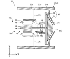
- Embodiment 1 1 and 2 are cross-sectional views schematically showing the structure of the electric blower 1 according to Embodiment 1 of the present invention.
- FIG. 2 is a view showing a state where the electric blower 1 shown in FIG. 1 is rotated in the circumferential direction.
- the “circumferential direction” refers to the direction of the arrow D1 shown in FIG. 3 and is, for example, the rotational direction of the moving blade 31.
- the electric blower 1 has a motor 10, a housing 20, and a blower 30.
- the motor 10 is, for example, a permanent magnet synchronous motor.
- a motor other than a permanent magnet synchronous motor may be used.
- the permanent magnet synchronous motor refers to a synchronous motor having a permanent magnet (ferromagnetic material) and using the permanent magnet (ferromagnetic material) in the field.
- the motor 10 has a motor frame 11 (also simply referred to as a frame), a stator 12, a rotor 13, a shaft 14, bearings 15a and 15b, and a vane support 16 (FIG. 2).
- the housing 20 is provided with a first portion 21, a second portion 22, a third portion 23, a fourth portion 24, a motor support portion 25, a first opening 26a, and a first portion. And a second opening 26b communicating with the opening 26a.
- the blower unit 30 has a rotating blade 31 and a stationary blade 32 that does not rotate.
- the blower 30 produces a flow of air.
- the moving blade 31 is, for example, a diagonal flow fan. However, the moving blade 31 is not limited to the diagonal flow fan.
- a mixed flow fan is a fan that generates an air flow in a direction inclined with respect to the rotation axis of a moving blade. The moving blades 31 rotate with the rotation of the motor 10 (specifically, the rotor 13 and the shaft 14).
- the stator 12 is fixed to the inner side (inner wall) of the motor frame 11.
- the rotor 13 is rotatably inserted inside the stator 12 via an air gap.
- One end side of the shaft 14 is fixed to an axial hole formed in the rotor 13.
- the other end side of the shaft 14 is rotatably inserted into the bearings 15 a and 15 b and fixed to the moving blade 31.
- the stator support 16 is fixed to the motor frame 11 and supports the stator 32.
- the housing 20 is formed in a tubular shape. That is, the inside of the housing 20 is hollow.
- the first portion 21 circumferentially surrounds the moving blade 31.
- the second portion 22 circumferentially surrounds the motor 10.
- the third portion 23 is provided between the first portion 21 and the second portion 22.
- the third portion 23 is integrally formed with the first portion 21 and the second portion 22.
- the fourth portion 24 is formed to face the moving blade 31 and forms a first opening 26 a.
- the fourth portion 24 is integrally formed with the first portion 21.
- the motor support 25 supports the motor 10.
- FIG. 3 is a cross-sectional view taken along line C3-C3 in FIG. As shown in FIGS. 1 and 3, the inner diameter r2 of the second portion 22 is smaller than the inner diameter r1 of the first portion 21.
- FIG. 4 is a view showing the flow of air generated by the rotation of the moving blades 31 in the electric blower 1.
- the electric blower 1 has a first path 41 through which the air passes, a second path 42 through which the air passing through the first path 41 passes, and a third through which the air passing through the second path 42 passes. And a path 43.
- the first path 41 is formed between the housing 20 (specifically, the first portion 21) and the blower 30 (specifically, the stationary blade 32).
- the second path 42 is formed between the first path 41 and the third path 43.
- the third path 43 is formed between the housing 20 (specifically, the second portion 22) and the motor 10 (specifically, the motor frame 11).
- the electric blower 1 When the electric blower 1 is powered on, the electric power is supplied to the motor 10, and the motor 10 rotates the moving blades 31. As the moving blades 31 rotate, an air flow is generated in the electric blower 1. Specifically, air flows from the outside of the electric blower 1 through the first opening 26 a into the electric blower 1. When the bucket 31 is rotating, air flows toward the second opening 26b.
- the air flow generated by the moving blade 31 passes through the stationary blade 32 and flows into the first path 41.
- the air flows in the first direction D1.
- the first direction D1 is a direction parallel to the shaft 14.
- the first direction D1 is a direction from the first opening 26a to the second opening 26b and is parallel to the X axis.
- the first direction D1 may not be exactly parallel to the shaft 14.
- the air that has passed through the first path 41 flows into the second path 42.
- the air flows in the second direction D2.
- the second direction D2 is a direction along the inner surface of the third portion 23 on the XZ plane.
- the second direction D2 is a direction from the first opening 26 a to the second opening 26 b and along the inner surface of the third portion 23. .
- the third path 43 is formed between the second portion 22 and the motor 10.
- the third direction D3 is a direction parallel to the shaft 14.
- the third direction D3 is a direction from the first opening 26a to the second opening 26b and is parallel to the X axis. That is, in the example shown in FIG. 4, the first direction D1 and the third direction D3 are parallel to each other.
- the third direction D3 may not be exactly parallel to the shaft 14.
- the air having passed through the third path 43 is discharged to the outside of the electric blower 1 from the second opening 26 b.
- FIG. 5 is a cross sectional view schematically showing a structure of an electric blower 1a according to a first modification of the first embodiment.
- the electric blower 1a according to the first modification differs from the electric blower 1 according to the first embodiment in that the motor frame 11a of the motor 10a has a through hole 17, and the other points are the same.
- At least one through hole 17 for cooling the motor 10a (specifically, inside the motor 10a) is formed at an end of the motor frame 11a in the rotation axis direction (the X axis direction in FIG. 5). .
- the air passing through the second path 42 flows into the third path 43 and also flows into the interior of the motor frame 11 a through the through hole 17.
- the air flowing into the motor frame 11a is discharged to the outside of the motor 10a through a through hole (air passage) formed in the stator 12 and a gap between the rotor 13 and the stator 12.
- the motor 10a can be cooled, and the stability of the electric blower 1a can be improved.
- Modification 2 6 and 7 are cross sectional views schematically showing the structure of an electric blower 1b according to a second modification of the first embodiment.
- FIG. 7 is a view showing a state in which the electric blower 1b shown in FIG. 6 is rotated in the circumferential direction.
- the electric blower 1b according to the second modification differs from the motor 10 of the electric blower 1 according to the first embodiment in the motor 10b (specifically, the arrangement of the bearings 15a and 15b and the structure of the motor frame 11b), The points are the same as each other.
- the bearings 15a and 15b are respectively fixed to both sides of the motor frame 11b in the rotational axis direction (the X axis direction in the examples shown in FIGS. 6 and 7). Therefore, the rotor 13 and the shaft 14 are rotatably supported by the double-supported structure. Thereby, the drive of the motor 10b can be stabilized.
- FIG. 8 is a cross sectional view schematically showing a structure of an electric blower 1c according to a third modification of the first embodiment.
- the electric blower 1c according to the third modification differs from the motor 10 of the electric blower 1 according to the first embodiment in the motor 10c (specifically, the arrangement of the bearings 15a and 15b and the structure of the motor frame 11c). The points are the same as each other.
- a plurality of through holes 17 for cooling the motor 10c are formed at both ends of the motor frame 11c in the rotational axis direction (the X axis direction in FIG. 8).
- the air passing through the second path 42 flows into the third path 43 and also flows into the motor frame 11 c from the through hole 17 on the first opening 26 a side.
- the air flowing into the motor frame 11c passes through the through hole (air passage) formed in the stator 12 and the air gap between the rotor 13 and the stator 12, and from the through hole 17 on the second opening 26b side It is discharged to the outside of 10c. Thereby, the motor 10c can be cooled, and the stability of the electric blower 1c can be improved.
- the bearings 15a and 15b are respectively fixed to both sides of the motor frame 11c in the rotational axis direction (the X axis direction in the example shown in FIG. 8). Therefore, the rotor 13 and the shaft 14 are rotatably supported by the double-supported structure. Thereby, the drive of the motor 10c can be stabilized.
- FIGS. 9, 10 and 11 are cross sectional views schematically showing the structure of an electric blower 1 d as a comparative example.
- FIG. 10 is a view showing a state in which the electric blower 1 d shown in FIG. 9 is rotated in the circumferential direction.
- FIG. 11 is a diagram showing the flow of air generated by the rotation of the moving blades 31 in the electric blower 1d.
- 12 and 13 schematically show the structure of an electric blower 1e according to a modification of the electric blower 1d as a comparative example.
- FIG. 13 is a view showing a state where the electric blower 1e shown in FIG. 12 is rotated in the circumferential direction.
- the rotor 13 and the shaft 14 are rotatably supported by a double-supported structure.
- the other points in the electric blower 1e are the same as the electric blower 1d shown in FIGS.
- the case 20 d of the electric blower 1 d is different from the case 20 according to the first embodiment (including each modification). Specifically, the structures of the first portion 21d, the second portion 22d, and the third portion 23d of the housing 20d are different. That is, the inner diameter r2 of the second portion 22 is equal to the inner diameter r1 of the first portion 21.
- the second path 42 and the third path 43 have no obstacle that inhibits the air flow, so that it is possible to prevent the decrease in aerodynamic efficiency.
- the second path 42 and the third path 43 are enlarged in the radial direction of the electric fan 1d (for example, in the Z-axis direction in FIG. 9).
- pressure loss is likely to occur.
- An increase in pressure loss causes a decrease in the aerodynamic efficiency of the electric blower.
- air can not be in close contact with the motor frame 11, so the motor 10 does not dissipate heat sufficiently.
- the path width of the second path 42 and the third path 43 is small.
- the inner diameter r2 of the second portion 22 is shorter than the inner diameter r1 of the first portion 21.
- the expansion of the air path (for example, the second path 42) in the radial direction is suppressed. Therefore, an increase in pressure loss when the air flow generated by the moving blades 31 flows from the first path 41 to the second path 42 is suppressed, and the aerodynamic efficiency is improved. Thereby, an electric blower with high aerodynamic efficiency can be provided.
- the motor 10 can dissipate heat sufficiently. Thereby, the life of electric blower 1 (specifically, motor 10) can be extended.
- At least one through hole 17 for cooling motor 10a is formed in motor frame 11a, so that motor 10a can be cooled.
- the heat radiation effect of the electric blower 1a can be enhanced. Thereby, the stability of the electric blower 1a can be improved.
- the rotor 13 and the shaft 14 are rotatably supported by a double-supported structure. Thereby, the drive of the motor 10b can be stabilized.
- the motor 10c since the plurality of through holes 17 for cooling the motor 10c are formed in the motor frame 11c, the motor 10c can be cooled.
- the heat radiation effect in the electric blower 1c can be enhanced.
- the stability of the electric blower 1c can be improved.
- the rotor 13 and the shaft 14 are rotatably supported by the double-supported structure, the drive of the motor 10c can be stabilized.
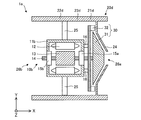
- FIG. 15 is a view showing a state in which electric blower 2 shown in FIG. 14 is rotated in the circumferential direction.
- the motor 100 (specifically, the structure of the motor frame 111) is different from the motor 10 of the electric blower 1 according to the first embodiment, and the other points are the same.
- the same reference numerals as the reference numerals of the elements described in the first embodiment are used for the reference numerals of the elements which are the same as or correspond to the elements described in the first embodiment (including each modification).
- the electric blower 2 has a motor 100, a housing 20, and a blower 30.
- the motor 100 is, for example, a permanent magnet synchronous motor. However, as the motor 100, a motor other than a permanent magnet synchronous motor may be used.
- the motor 100 includes a motor frame 111 (also referred to simply as a frame), a stator 12, a rotor 13, a shaft 14, bearings 15a and 15b, and a vane support portion 16.
- the housing 20 is provided with a first portion 21, a second portion 22, a third portion 23, a fourth portion 24, a motor support portion 25, a first opening 26a, and a first portion. And a second opening 26b communicating with the opening 26a.
- the blower unit 30 has a moving blade 31 and a stationary blade 32.
- the blower 30 produces a flow of air.
- the moving blade 31 is, for example, a diagonal flow fan. However, the moving blade 31 is not limited to the diagonal flow fan.
- the motor frame 111 has a bearing holding portion 112 for holding the bearings 15a and 15b, a stator holding portion 113 for holding the stator 12, and a guide portion 114 (also referred to as a projecting portion).
- the bearing holding portion 112, the stator holding portion 113, and the guide portion 114 are integrally formed with each other.
- the guide portion 114 is provided inside the third portion 23 in the radial direction of the electric blower 2 (the direction orthogonal to the rotation axis of the moving blade 31), and extends in the second direction D2. That is, the guide portion 114 faces the third portion 23. In the example shown in FIGS. 14 and 15, the guide portion 114 protrudes from the stator holding portion 113 toward the blower portion 30.
- the inner diameter r2 of the second portion 22 is shorter than the inner diameter r1 of the first portion 21.
- FIG. 16 is a view showing the flow of air generated by the rotation of the moving blades 31 in the electric blower 2.
- the moving blades 31 rotate to generate an air flow. Specifically, air flows from the outside of the electric blower 2 through the first opening 26 a into the electric blower 2. The air flow generated by the moving blades 31 passes through the stationary blades 32 and flows into the first path 41. In the first path 41, the air flows in the first direction D1.
- the air that has passed through the first path 41 flows into the second path 42.
- the second path 42 is formed between the third portion 23 and the guide portion 114. Therefore, the guide portion 114 guides the air having passed through the first path 41 in the second direction D2 together with the third portion 23.
- the air having passed through the first path 41 flows in the second path D2 in the second direction D2.
- the air that has passed through the second path 42 flows into the third path 43.
- the third path 43 is formed between the second portion 22 and the motor 100 (specifically, the stator holding portion 113). In the third path 43, air flows in the third direction D3.
- the air having passed through the third path 43 is discharged to the outside of the electric blower 2 from the second opening 26 b.
- Modification 1 17 and 18 are cross sectional views schematically showing a structure of an electric blower 2a according to a first modification of the second embodiment.
- the electric blower 2a according to the first modification differs from the electric blower 2 according to the second embodiment in that the motor frame 111a of the motor 100a has a through hole 17, and the other points are the same.
- At least one through hole 17 for cooling the motor 100a is formed in the motor frame 111a.
- the air that has passed through the second path 42 flows into the third path 43 and flows into the motor frame 111 a from the through hole 17.
- the air flowing into the motor frame 111a is discharged to the outside of the motor 100a through the through holes (air passage) formed in the stator 12 and the air gap between the rotor 13 and the stator 12.
- the motor 100a can be cooled, and the stability of the electric blower 2a can be improved.
- the width t1 of the first path 41 shown in FIG. 18 is a width in a direction orthogonal to the first direction D1 on the XZ plane.
- the width t2 of the second path 42 shown in FIG. 18 is a width in a direction orthogonal to the second direction D2 on the XZ plane.
- the width t3 of the third path 43 shown in FIG. 18 is a width in a direction orthogonal to the third direction D3 on the XZ plane.
- the amount of air flowing into the electric blower 2a is determined by the width t1 of the first path 41 and the inner diameter r1 of the first portion 21.
- the inner diameter r2 of the second portion 22 is smaller than the inner diameter r1 of the first portion 21.
- the width t2 of the second path 42 is preferably larger than the width t1 of the first path 41.
- the width t3 of the third path 43 (in particular, the width of the outlet of the third path 43) is desirably larger than the width t1 of the first path 41 and the width t2 of the second path 42.
- Modification 2 19 and 20 are cross sectional views schematically showing the structure of an electric blower 2b according to a second modification of the second embodiment.
- FIG. 20 is a view showing a state where the electric blower 2b shown in FIG. 19 is rotated in the circumferential direction.
- the electric blower 2b according to the second modification differs from the motor 100 of the electric blower 2 according to the second embodiment in the motor 100b (specifically, the arrangement of the bearings 15a and 15b and the structure of the motor frame 111b), The points are the same as each other.
- the bearings 15a and 15b are respectively fixed to both sides of the motor frame 111b in the rotational axis direction (the X axis direction in the example shown in FIGS. 18 and 19). Therefore, the rotor 13 and the shaft 14 are rotatably supported by the double-supported structure. Thereby, the drive of the motor 100b can be stabilized.
- FIG. 21 is a cross sectional view schematically showing a structure of an electric blower 2c according to a third modification of the second embodiment.
- the electric blower 2c according to the third modification differs from the motor 100 of the electric blower 2 according to the second embodiment in the motor 100c (specifically, the arrangement of the bearings 15a and 15b and the structure of the motor frame 111c), The points are the same as each other.
- a plurality of through holes 17 for cooling the motor 100c are formed in the motor frame 111c.
- the air that has passed through the second path 42 flows into the third path 43 and also flows into the motor frame 111 c from the through hole 17 on the first opening 26 a side.
- the air flowing into the motor frame 111c passes through the through hole (air passage) formed in the stator 12 and the air gap between the rotor 13 and the stator 12, and the through hole 17 on the second opening 26b side It is discharged to the outside of 100c.
- the motor 100c can be cooled, and the stability of the electric blower 2c can be improved.
- the bearings 15a and 15b are respectively fixed to both sides of the motor frame 111c in the rotational axis direction (the X axis direction in the example shown in FIG. 21). Therefore, the rotor 13 and the shaft 14 are rotatably supported by the double-supported structure. Thereby, the drive of the motor 100c can be stabilized.
- the electric blower 2 according to the second embodiment has the same effect as the electric blower 1 according to the first embodiment. Furthermore, the electric blower 2 has the effects described below.
- the inner diameter r2 of the second portion 22 is shorter than the inner diameter r1 of the first portion 21. Furthermore, the electric blower 2 has a guide portion 114 facing the third portion 23. Thereby, the expansion of the air path (for example, the second path 42) in the radial direction is restricted. Therefore, the increase in pressure loss when the air flow generated by the moving blades 31 flows from the first path 41 to the second path 42 is further suppressed, and the aerodynamic efficiency is further improved.
- the motor frame 111a is formed with at least one through hole 17 for cooling the motor 100a (specifically, the inside of the motor 100a).
- the motor 100a can be cooled, and the heat radiation effect of the electric blower 2a can be enhanced.
- the stability of the electric blower 2a can be improved.
- the rotor 13 and the shaft 14 are rotatably supported by a double-supported structure. Thereby, the drive of the motor 100b can be stabilized.
- motor frame 111c is provided with a plurality of through holes 17 for cooling motor 100c (specifically, the inside of motor 100c). Therefore, the motor 100c can be cooled, and the heat radiation effect of the electric blower 2c can be enhanced. Thereby, the stability of the electric blower 2c can be improved. Furthermore, since the rotor 13 and the shaft 14 are rotatably supported by the double-supported structure, the drive of the motor 100c can be stabilized.
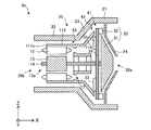
- FIG. 22 is a cross sectional view schematically showing a structure of the electric blower 3 according to the third embodiment.
- FIG. 23 (a) is a plan view showing the structure around the stator blade 32
- FIG. 23 (b) is a cross-sectional view along the line 23b-23b in FIG. 23 (a).
- the electric blower 3 according to the third embodiment has at least one wind guide plate 33.
- the other points are the same as in the first embodiment (specifically, the first modification of the first embodiment).
- the same reference numerals as the reference numerals of the elements described in the first embodiment are used for the reference numerals of the elements that are the same as or correspond to the elements described in the first embodiment (including each modification).
- At least one wind guide plate 33 is provided between the vane 32 and the motor 10a.
- the air guide plate 33 guides the air flow generated by the rotation of the moving blades 31 toward the motor 10 a.
- the main plate 34 has a first surface 34 a which is a front side and a second surface 34 b which is a back side.
- a plurality of vanes 32 are formed on the first surface 34 a, and a plurality of baffle plates 33 are formed on the second surface 34 b.
- the plurality of vanes 32 and the plurality of baffle plates 33 are spirally arranged so as to be in antiphase with each other.
- a part of the air flow that has passed through the first path 41 is guided radially inward by the air guide plate 33. As a result, part of the air flow that has passed through the first path 41 can easily flow into the motor frame 11a.
- FIG. 24 is a cross sectional view schematically showing a structure of an electric blower 3 according to a modification of the third embodiment.
- the electric blower 3a according to the modification differs from the electric blower 3 according to the third embodiment in the structure of the motor frame 111a, and the other points are the same.
- the structure and function of motor frame 111a are the same as in the first modification of the second embodiment.
- the electric blower 3a which concerns on a modification has the guide part 114 which faces the 3rd part 23. As shown in FIG. Thereby, the expansion of the air path (for example, the second path 42) in the radial direction is restricted. Therefore, compared to the electric blower 3 according to the third embodiment, an increase in pressure loss when the air flow generated by the moving blades 31 flows from the first path 41 to the second path 42 is further suppressed, and the aerodynamic efficiency is improved. It will be further improved.
- the electric blower 3 according to the third embodiment has the same effect as the electric blower 1 according to the first embodiment. Furthermore, the electric blower 3 has the effects described below.
- the electric blower 3 According to the electric blower 3 according to the third embodiment, it is possible to easily flow a part of the air flow of the air flow having passed through the first path 41 into the motor frame 11a. Thereby, the heat dissipation effect in the motor 10a can be enhanced.
- an increase in pressure loss when the air flow generated by the moving blades 31 flows from the first path 41 to the second path 42 is further suppressed. Aerodynamic efficiency can be further improved.
- FIG. 25 is a side view schematically showing the vacuum cleaner 5 according to the fourth embodiment.
- the electric vacuum cleaner 5 has a main body 51, a dust collection unit 52 for collecting dust, a duct 53, a suction nozzle 54, and a grip unit 55.
- the main body 51 includes an electric blower 51a that generates a suction force (suction wind) and an exhaust port 51b.
- the electric blower 51a is the electric blower 1 according to the first embodiment (including each modification), the electric blower 2 according to the second embodiment (including each modification), or the electric blower 3 according to the third embodiment Each modification is included).
- the dust collection unit 52 is attached to the main body 51.
- the dust collection unit 52 may be provided inside the main body 51.
- the dust collection unit 52 is a container having a filter that separates dust and air.
- the suction nozzle 54 is attached to the end of the duct 53.
- the vacuum cleaner 5 which concerns on Embodiment 4 has one of the electric blowers demonstrated by Embodiment 1-3, it has an effect similar to the effect demonstrated by Embodiment 1-3.
- the vacuum cleaner 5 which concerns on Embodiment 4 since the increase in the pressure loss in the electric blower 51a is suppressed and aerodynamic efficiency is improved, the vacuum cleaner with high suction power can be provided.
- FIG. 26 is a perspective view schematically showing a hand dryer 6 as a hand dryer according to the fifth embodiment.
- the hand dryer 6 as a hand dryer has a housing 61 (also referred to as a casing) and an electric blower 64.
- the housing 61 has an air inlet 62 and an air outlet 63.
- the electric blower 64 is fixed inside the housing 61.
- the electric blower 64 is the electric blower 1 according to the first embodiment (including each modification), the electric blower 2 according to the second embodiment (including each modification), or the electric blower 3 according to the third embodiment Each modification is included).
- the electric blower 64 sucks and blows air by generating an air flow. Specifically, the electric blower 64 sucks the air outside the housing 61 through the air inlet 62 and sends the air outside the housing 61 through the air outlet 63.
- the hand dryer 6 When the hand dryer 6 is powered on, electric power is supplied to the electric blower 64, and the electric blower 64 can be driven. While the electric blower 64 is driven, air outside the hand dryer 6 is sucked from the air inlet 62. The air drawn from the air inlet 62 passes through the inside of the electric blower 64 and is discharged from the air outlet 63. By holding the hand near the air outlet 63, the user of the hand dryer 6 can blow off the water droplets adhering to the hand and can dry the hand.
- the hand dryer 6 according to the fifth embodiment includes the electric blower according to any one of the first to third embodiments, and thus has the same effect as the effect described in the first to third embodiments.
- the increase in pressure loss in the electric blower 64 is suppressed, and the aerodynamic efficiency is improved, so a highly efficient vacuum cleaner can be provided.
Landscapes
- Engineering & Computer Science (AREA)
- Mechanical Engineering (AREA)
- General Engineering & Computer Science (AREA)
- Physics & Mathematics (AREA)
- Thermal Sciences (AREA)
- Structures Of Non-Positive Displacement Pumps (AREA)
- Electric Suction Cleaners (AREA)
Abstract
Priority Applications (4)
| Application Number | Priority Date | Filing Date | Title |
|---|---|---|---|
| PCT/JP2017/022989 WO2018235221A1 (fr) | 2017-06-22 | 2017-06-22 | Soufflante de production d'air électrique, aspirateur électrique, et sèche-mains |
| EP17914605.5A EP3643925A4 (fr) | 2017-06-22 | 2017-06-22 | Soufflante de production d'air électrique, aspirateur électrique, et sèche-mains |
| US16/606,800 US11454246B2 (en) | 2017-06-22 | 2017-06-22 | Electric blower, vacuum cleaner, and hand drying device |
| JP2019524793A JP6719670B2 (ja) | 2017-06-22 | 2017-06-22 | 電動送風機、電気掃除機、及び手乾燥装置 |
Applications Claiming Priority (1)
| Application Number | Priority Date | Filing Date | Title |
|---|---|---|---|
| PCT/JP2017/022989 WO2018235221A1 (fr) | 2017-06-22 | 2017-06-22 | Soufflante de production d'air électrique, aspirateur électrique, et sèche-mains |
Publications (1)
| Publication Number | Publication Date |
|---|---|
| WO2018235221A1 true WO2018235221A1 (fr) | 2018-12-27 |
Family
ID=64736934
Family Applications (1)
| Application Number | Title | Priority Date | Filing Date |
|---|---|---|---|
| PCT/JP2017/022989 Ceased WO2018235221A1 (fr) | 2017-06-22 | 2017-06-22 | Soufflante de production d'air électrique, aspirateur électrique, et sèche-mains |
Country Status (4)
| Country | Link |
|---|---|
| US (1) | US11454246B2 (fr) |
| EP (1) | EP3643925A4 (fr) |
| JP (1) | JP6719670B2 (fr) |
| WO (1) | WO2018235221A1 (fr) |
Cited By (2)
| Publication number | Priority date | Publication date | Assignee | Title |
|---|---|---|---|---|
| FR3101117A1 (fr) * | 2019-09-25 | 2021-03-26 | Sifat Aeraulique | Ventilateur centrifuge axial à rendement amélioré |
| US20220010799A1 (en) * | 2020-07-10 | 2022-01-13 | Lg Electronics Inc. | Air circulator and air cleaner including air circulator |
Families Citing this family (1)
| Publication number | Priority date | Publication date | Assignee | Title |
|---|---|---|---|---|
| GB2575814B (en) * | 2018-07-23 | 2020-12-09 | Dyson Technology Ltd | A wearable air purifier |
Citations (6)
| Publication number | Priority date | Publication date | Assignee | Title |
|---|---|---|---|---|
| JP2000249098A (ja) * | 1999-02-26 | 2000-09-12 | Hitachi Ltd | 電動送風機および電気掃除機 |
| JP2011052591A (ja) * | 2009-09-02 | 2011-03-17 | Panasonic Corp | 電動送風機およびそれを用いた電気掃除機 |
| JP2012202282A (ja) * | 2011-03-25 | 2012-10-22 | Panasonic Corp | 電動送風機およびそれを用いた電気掃除機 |
| JP2013079625A (ja) * | 2011-10-05 | 2013-05-02 | Mitsubishi Electric Corp | 電動遠心送風機及びこれを用いた電気掃除機 |
| US20130169082A1 (en) * | 2011-12-29 | 2013-07-04 | Samsung Electro-Mechanics Co., Ltd. | Fan motor assembly |
| JP2014015853A (ja) * | 2012-07-05 | 2014-01-30 | Nippon Densan Corp | 遠心ファン |
Family Cites Families (15)
| Publication number | Priority date | Publication date | Assignee | Title |
|---|---|---|---|---|
| US2658665A (en) * | 1950-12-07 | 1953-11-10 | Hoover Co | Multistage fan for suction cleaners |
| JPS6270697A (ja) | 1985-09-20 | 1987-04-01 | Matsushita Electric Ind Co Ltd | 電動送風機 |
| JP3747630B2 (ja) | 1998-05-25 | 2006-02-22 | 松下電器産業株式会社 | 電動送風機 |
| JP3532779B2 (ja) | 1998-12-17 | 2004-05-31 | シャープ株式会社 | ファンモータ装置及び環流式電気掃除機 |
| JP2000316747A (ja) * | 1999-05-10 | 2000-11-21 | Mitsubishi Electric Corp | 乾燥装置 |
| JP2005307985A (ja) * | 2005-06-17 | 2005-11-04 | Matsushita Electric Ind Co Ltd | 電気掃除機用電動送風機及びこれを用いた電気掃除機 |
| FR2908482B1 (fr) | 2006-11-13 | 2010-04-02 | Airfan | Appareil de delivrance regulee d'un gaz notamment appareil d'assistance respiratoire |
| JP2013024134A (ja) | 2011-07-21 | 2013-02-04 | Panasonic Corp | 電動送風機ならびに電気掃除機 |
| JP6155544B2 (ja) * | 2012-03-12 | 2017-07-05 | 日本電産株式会社 | 遠心ファン |
| GB2513664B (en) * | 2013-05-03 | 2016-01-06 | Dyson Technology Ltd | Compressor |
| JP6417771B2 (ja) | 2014-07-31 | 2018-11-07 | 日本電産株式会社 | 電動送風機 |
| MX2016006402A (es) * | 2015-05-21 | 2016-11-21 | Johnson Electric Sa | Motor monofasico, dispositivo generador de flujo de aire, y aparato electrico. |
| EP3133723A1 (fr) | 2015-08-18 | 2017-02-22 | Johnson Electric S.A. | Dispositif de génération de fluide et appareil électrique utilisant celui-ci |
| JP6717029B2 (ja) | 2015-11-09 | 2020-07-01 | 日本電産株式会社 | 送風装置、および清掃機器 |
| JP2018105269A (ja) * | 2016-12-28 | 2018-07-05 | 日本電産株式会社 | 送風装置及びそれを備えた掃除機 |
-
2017
- 2017-06-22 EP EP17914605.5A patent/EP3643925A4/fr not_active Withdrawn
- 2017-06-22 JP JP2019524793A patent/JP6719670B2/ja active Active
- 2017-06-22 US US16/606,800 patent/US11454246B2/en active Active
- 2017-06-22 WO PCT/JP2017/022989 patent/WO2018235221A1/fr not_active Ceased
Patent Citations (6)
| Publication number | Priority date | Publication date | Assignee | Title |
|---|---|---|---|---|
| JP2000249098A (ja) * | 1999-02-26 | 2000-09-12 | Hitachi Ltd | 電動送風機および電気掃除機 |
| JP2011052591A (ja) * | 2009-09-02 | 2011-03-17 | Panasonic Corp | 電動送風機およびそれを用いた電気掃除機 |
| JP2012202282A (ja) * | 2011-03-25 | 2012-10-22 | Panasonic Corp | 電動送風機およびそれを用いた電気掃除機 |
| JP2013079625A (ja) * | 2011-10-05 | 2013-05-02 | Mitsubishi Electric Corp | 電動遠心送風機及びこれを用いた電気掃除機 |
| US20130169082A1 (en) * | 2011-12-29 | 2013-07-04 | Samsung Electro-Mechanics Co., Ltd. | Fan motor assembly |
| JP2014015853A (ja) * | 2012-07-05 | 2014-01-30 | Nippon Densan Corp | 遠心ファン |
Non-Patent Citations (1)
| Title |
|---|
| See also references of EP3643925A4 |
Cited By (3)
| Publication number | Priority date | Publication date | Assignee | Title |
|---|---|---|---|---|
| FR3101117A1 (fr) * | 2019-09-25 | 2021-03-26 | Sifat Aeraulique | Ventilateur centrifuge axial à rendement amélioré |
| US20220010799A1 (en) * | 2020-07-10 | 2022-01-13 | Lg Electronics Inc. | Air circulator and air cleaner including air circulator |
| US12152594B2 (en) * | 2020-07-10 | 2024-11-26 | Lg Electronics Inc. | Air circulator and air cleaner including air circulator |
Also Published As
| Publication number | Publication date |
|---|---|
| JP6719670B2 (ja) | 2020-07-08 |
| US11454246B2 (en) | 2022-09-27 |
| US20200318646A1 (en) | 2020-10-08 |
| EP3643925A4 (fr) | 2020-06-17 |
| EP3643925A1 (fr) | 2020-04-29 |
| JPWO2018235221A1 (ja) | 2019-11-07 |
Similar Documents
| Publication | Publication Date | Title |
|---|---|---|
| CN114555952B (zh) | 电动送风机以及具备该电动送风机的电动吸尘器 | |
| JP7516221B2 (ja) | 電動送風機及びそれを備えた電気掃除機 | |
| JP2003139094A (ja) | 電気掃除機用電動送風機及びこれを用いた電気掃除機 | |
| JP6798011B2 (ja) | 電動送風機、電気掃除機、及び手乾燥装置 | |
| JP6840243B2 (ja) | 電動送風機、電気掃除機、及び手乾燥装置 | |
| JP6719670B2 (ja) | 電動送風機、電気掃除機、及び手乾燥装置 | |
| US6461124B1 (en) | Through-flow blower with cooling fan | |
| JP4942795B2 (ja) | 電気掃除機 | |
| KR102585277B1 (ko) | 팬 모터 | |
| JP7500345B2 (ja) | 電動送風機及びそれを備えた電気掃除機 | |
| CN103999336A (zh) | 用于冷却电机的装置和方法 | |
| KR100808205B1 (ko) | 진공청소기용 모터 어셈블리 | |
| JP7477432B2 (ja) | 電動送風機及びそれを備えた電気掃除機 | |
| KR100437037B1 (ko) | 청소기용 원심송풍기 | |
| JP7842656B2 (ja) | 電動送風機およびそれを備えた電気掃除機 | |
| JP2005137064A (ja) | 電動送風機及び電気掃除機 | |
| JP2004197587A (ja) | 電動送風機 | |
| JP7428630B2 (ja) | 電動送風機及びそれを備えた電気掃除機 | |
| JP2013170531A (ja) | 電動送風機、電気掃除機 | |
| KR100437036B1 (ko) | 청소기용 원심송풍기 | |
| WO2006067736A1 (fr) | Moteur electrique | |
| JP2011185113A (ja) | 冷却ファン装置 | |
| KR100445649B1 (ko) | 진공청소기용 모터 | |
| KR100408055B1 (ko) | 진공청소기용 팬-모터의 하우징 공기유로구조 | |
| JP2025124209A (ja) | 羽根車、送風機、送風機付衣服 |
Legal Events
| Date | Code | Title | Description |
|---|---|---|---|
| 121 | Ep: the epo has been informed by wipo that ep was designated in this application |
Ref document number: 17914605 Country of ref document: EP Kind code of ref document: A1 |
|
| WWE | Wipo information: entry into national phase |
Ref document number: 2019524793 Country of ref document: JP |
|
| NENP | Non-entry into the national phase |
Ref country code: DE |
|
| ENP | Entry into the national phase |
Ref document number: 2017914605 Country of ref document: EP Effective date: 20200122 |
|
| WWW | Wipo information: withdrawn in national office |
Ref document number: 2017914605 Country of ref document: EP |