WO2018235375A1 - 現像カートリッジ - Google Patents
現像カートリッジ Download PDFInfo
- Publication number
- WO2018235375A1 WO2018235375A1 PCT/JP2018/012300 JP2018012300W WO2018235375A1 WO 2018235375 A1 WO2018235375 A1 WO 2018235375A1 JP 2018012300 W JP2018012300 W JP 2018012300W WO 2018235375 A1 WO2018235375 A1 WO 2018235375A1
- Authority
- WO
- WIPO (PCT)
- Prior art keywords
- holder
- coupling
- developing cartridge
- state
- developing
- Prior art date
- Legal status (The legal status is an assumption and is not a legal conclusion. Google has not performed a legal analysis and makes no representation as to the accuracy of the status listed.)
- Ceased
Links
Images


Classifications
-
- G—PHYSICS
- G03—PHOTOGRAPHY; CINEMATOGRAPHY; ANALOGOUS TECHNIQUES USING WAVES OTHER THAN OPTICAL WAVES; ELECTROGRAPHY; HOLOGRAPHY
- G03G—ELECTROGRAPHY; ELECTROPHOTOGRAPHY; MAGNETOGRAPHY
- G03G21/00—Arrangements not provided for by groups G03G13/00 - G03G19/00, e.g. cleaning, elimination of residual charge
- G03G21/16—Mechanical means for facilitating the maintenance of the apparatus, e.g. modular arrangements
- G03G21/1661—Mechanical means for facilitating the maintenance of the apparatus, e.g. modular arrangements means for handling parts of the apparatus in the apparatus
- G03G21/1676—Mechanical means for facilitating the maintenance of the apparatus, e.g. modular arrangements means for handling parts of the apparatus in the apparatus for the developer unit
-
- G—PHYSICS
- G03—PHOTOGRAPHY; CINEMATOGRAPHY; ANALOGOUS TECHNIQUES USING WAVES OTHER THAN OPTICAL WAVES; ELECTROGRAPHY; HOLOGRAPHY
- G03G—ELECTROGRAPHY; ELECTROPHOTOGRAPHY; MAGNETOGRAPHY
- G03G15/00—Apparatus for electrographic processes using a charge pattern
- G03G15/01—Apparatus for electrographic processes using a charge pattern for producing multicoloured copies
- G03G15/0142—Structure of complete machines
- G03G15/0147—Structure of complete machines using a single reusable electrographic recording member
-
- G—PHYSICS
- G03—PHOTOGRAPHY; CINEMATOGRAPHY; ANALOGOUS TECHNIQUES USING WAVES OTHER THAN OPTICAL WAVES; ELECTROGRAPHY; HOLOGRAPHY
- G03G—ELECTROGRAPHY; ELECTROPHOTOGRAPHY; MAGNETOGRAPHY
- G03G15/00—Apparatus for electrographic processes using a charge pattern
- G03G15/06—Apparatus for electrographic processes using a charge pattern for developing
- G03G15/08—Apparatus for electrographic processes using a charge pattern for developing using a solid developer, e.g. powder developer
- G03G15/0822—Arrangements for preparing, mixing, supplying or dispensing developer
- G03G15/0863—Arrangements for preparing, mixing, supplying or dispensing developer provided with identifying means or means for storing process- or use parameters, e.g. an electronic memory
-
- G—PHYSICS
- G03—PHOTOGRAPHY; CINEMATOGRAPHY; ANALOGOUS TECHNIQUES USING WAVES OTHER THAN OPTICAL WAVES; ELECTROGRAPHY; HOLOGRAPHY
- G03G—ELECTROGRAPHY; ELECTROPHOTOGRAPHY; MAGNETOGRAPHY
- G03G15/00—Apparatus for electrographic processes using a charge pattern
- G03G15/06—Apparatus for electrographic processes using a charge pattern for developing
- G03G15/08—Apparatus for electrographic processes using a charge pattern for developing using a solid developer, e.g. powder developer
- G03G15/0822—Arrangements for preparing, mixing, supplying or dispensing developer
- G03G15/0865—Arrangements for supplying new developer
-
- G—PHYSICS
- G03—PHOTOGRAPHY; CINEMATOGRAPHY; ANALOGOUS TECHNIQUES USING WAVES OTHER THAN OPTICAL WAVES; ELECTROGRAPHY; HOLOGRAPHY
- G03G—ELECTROGRAPHY; ELECTROPHOTOGRAPHY; MAGNETOGRAPHY
- G03G15/00—Apparatus for electrographic processes using a charge pattern
- G03G15/06—Apparatus for electrographic processes using a charge pattern for developing
- G03G15/08—Apparatus for electrographic processes using a charge pattern for developing using a solid developer, e.g. powder developer
- G03G15/0896—Arrangements or disposition of the complete developer unit or parts thereof not provided for by groups G03G15/08 - G03G15/0894
-
- G—PHYSICS
- G03—PHOTOGRAPHY; CINEMATOGRAPHY; ANALOGOUS TECHNIQUES USING WAVES OTHER THAN OPTICAL WAVES; ELECTROGRAPHY; HOLOGRAPHY
- G03G—ELECTROGRAPHY; ELECTROPHOTOGRAPHY; MAGNETOGRAPHY
- G03G21/00—Arrangements not provided for by groups G03G13/00 - G03G19/00, e.g. cleaning, elimination of residual charge
- G03G21/16—Mechanical means for facilitating the maintenance of the apparatus, e.g. modular arrangements
- G03G21/1604—Arrangement or disposition of the entire apparatus
- G03G21/1623—Means to access the interior of the apparatus
-
- G—PHYSICS
- G03—PHOTOGRAPHY; CINEMATOGRAPHY; ANALOGOUS TECHNIQUES USING WAVES OTHER THAN OPTICAL WAVES; ELECTROGRAPHY; HOLOGRAPHY
- G03G—ELECTROGRAPHY; ELECTROPHOTOGRAPHY; MAGNETOGRAPHY
- G03G21/00—Arrangements not provided for by groups G03G13/00 - G03G19/00, e.g. cleaning, elimination of residual charge
- G03G21/16—Mechanical means for facilitating the maintenance of the apparatus, e.g. modular arrangements
- G03G21/1642—Mechanical means for facilitating the maintenance of the apparatus, e.g. modular arrangements for connecting the different parts of the apparatus
- G03G21/1647—Mechanical connection means
-
- G—PHYSICS
- G03—PHOTOGRAPHY; CINEMATOGRAPHY; ANALOGOUS TECHNIQUES USING WAVES OTHER THAN OPTICAL WAVES; ELECTROGRAPHY; HOLOGRAPHY
- G03G—ELECTROGRAPHY; ELECTROPHOTOGRAPHY; MAGNETOGRAPHY
- G03G21/00—Arrangements not provided for by groups G03G13/00 - G03G19/00, e.g. cleaning, elimination of residual charge
- G03G21/16—Mechanical means for facilitating the maintenance of the apparatus, e.g. modular arrangements
- G03G21/1642—Mechanical means for facilitating the maintenance of the apparatus, e.g. modular arrangements for connecting the different parts of the apparatus
- G03G21/1652—Electrical connection means
-
- G—PHYSICS
- G03—PHOTOGRAPHY; CINEMATOGRAPHY; ANALOGOUS TECHNIQUES USING WAVES OTHER THAN OPTICAL WAVES; ELECTROGRAPHY; HOLOGRAPHY
- G03G—ELECTROGRAPHY; ELECTROPHOTOGRAPHY; MAGNETOGRAPHY
- G03G21/00—Arrangements not provided for by groups G03G13/00 - G03G19/00, e.g. cleaning, elimination of residual charge
- G03G21/16—Mechanical means for facilitating the maintenance of the apparatus, e.g. modular arrangements
- G03G21/18—Mechanical means for facilitating the maintenance of the apparatus, e.g. modular arrangements using a processing cartridge, whereby the process cartridge comprises at least two image processing means in a single unit
- G03G21/1839—Means for handling the process cartridge in the apparatus body
- G03G21/1857—Means for handling the process cartridge in the apparatus body for transmitting mechanical drive power to the process cartridge, drive mechanisms, gears, couplings, braking mechanisms
- G03G21/1864—Means for handling the process cartridge in the apparatus body for transmitting mechanical drive power to the process cartridge, drive mechanisms, gears, couplings, braking mechanisms associated with a positioning function
-
- G—PHYSICS
- G03—PHOTOGRAPHY; CINEMATOGRAPHY; ANALOGOUS TECHNIQUES USING WAVES OTHER THAN OPTICAL WAVES; ELECTROGRAPHY; HOLOGRAPHY
- G03G—ELECTROGRAPHY; ELECTROPHOTOGRAPHY; MAGNETOGRAPHY
- G03G15/00—Apparatus for electrographic processes using a charge pattern
- G03G15/01—Apparatus for electrographic processes using a charge pattern for producing multicoloured copies
- G03G15/0105—Details of unit
- G03G15/0121—Details of unit for developing
-
- G—PHYSICS
- G03—PHOTOGRAPHY; CINEMATOGRAPHY; ANALOGOUS TECHNIQUES USING WAVES OTHER THAN OPTICAL WAVES; ELECTROGRAPHY; HOLOGRAPHY
- G03G—ELECTROGRAPHY; ELECTROPHOTOGRAPHY; MAGNETOGRAPHY
- G03G2215/00—Apparatus for electrophotographic processes
- G03G2215/01—Apparatus for electrophotographic processes for producing multicoloured copies
- G03G2215/0167—Apparatus for electrophotographic processes for producing multicoloured copies single electrographic recording member
- G03G2215/0174—Apparatus for electrophotographic processes for producing multicoloured copies single electrographic recording member plural rotations of recording member to produce multicoloured copy
- G03G2215/0177—Rotating set of developing units
-
- G—PHYSICS
- G03—PHOTOGRAPHY; CINEMATOGRAPHY; ANALOGOUS TECHNIQUES USING WAVES OTHER THAN OPTICAL WAVES; ELECTROGRAPHY; HOLOGRAPHY
- G03G—ELECTROGRAPHY; ELECTROPHOTOGRAPHY; MAGNETOGRAPHY
- G03G2221/00—Processes not provided for by group G03G2215/00, e.g. cleaning or residual charge elimination
- G03G2221/16—Mechanical means for facilitating the maintenance of the apparatus, e.g. modular arrangements and complete machine concepts
- G03G2221/163—Mechanical means for facilitating the maintenance of the apparatus, e.g. modular arrangements and complete machine concepts for the developer unit
Definitions
- the present invention relates to a developing cartridge.
- a developing cartridge is used in the image forming apparatus.
- the developing cartridge has a developing roller for supplying toner.
- the developer cartridge described in Patent Document 1 is attached to the drawer unit.
- the drawer unit is accommodated inside the image forming apparatus and is pulled out of the image forming apparatus.
- the drawer unit has a photosensitive drum. When the developing cartridge is attached to the drawer unit, the photosensitive drum and the developing roller face each other.
- the developing cartridge described in Patent Document 2 is mounted to the drum cartridge.
- the drum cartridge has a photosensitive drum.
- the photosensitive drum and the developing roller face each other. Then, in a state where the developing cartridge is mounted to the drum cartridge, the developing cartridge is mounted to the image forming apparatus.
- a developing cartridge having a storage medium is also known.
- the storage medium is, for example, an IC chip.
- the storage medium has an electrical contact surface.
- the developer cartridge has a holder for holding a storage medium.
- the developing cartridge has a coupling. For example, when the coupling and the holder are arranged side by side on the side surface of the cartridge, the size of the developing cartridge may be increased.
- An object of the present invention is to provide a structure capable of miniaturizing a developing cartridge.
- a first invention of the present application is a developing cartridge, and a housing capable of containing a developer, and a developing roller positioned at an end of the housing in a first direction, A developing roller rotatable about a first axis extending in two directions, a storage medium having an electrical contact surface, and a first holder movable in the first direction with respect to the housing A first holder for holding the electrical contact surface; and a second holder movable with the first holder in the first direction with respect to the housing, the third holder intersecting the electrical contact surface A second holder located apart from the first holder in a direction, and a coupling rotatable about a second axis extending in the second direction, the coupling being rotatable with the developing roller;
- the first holder and the second The loader is a first position in the first direction and a second position in the first direction with respect to the housing and the coupling, and is positioned closer to the developing roller than the first position. Between the first holder
- the developing cartridge according to the first aspect, wherein the elastic member is located between the first holder and the second holder, and the elastic member is disposed between the first state and the second state.
- the holder can be extended and / or retracted in a third direction, and the length of the third direction in the first state includes an elastic member longer than the length in the third direction in the second state, and the first holder Is movable in the third direction between the third position and the fourth position with respect to the second holder along with the extension and / or contraction of the elastic member, and the elastic member is the first member.
- the first holder When in the state, the first holder is at the third position, and when the elastic member is in the second state, the first holder is at the fourth position.
- a third invention of the present application is the developing cartridge of the first invention or the second invention, wherein when the first holder and the second holder are in the first position, a part of the coupling is the first one. It is located between the holder and the second holder.
- a fourth invention of the present application is the developing cartridge of the first invention to the third invention, which is a connecting portion which extends in the third direction and connects the first holder and the second holder.
- a portion of the coupling is the first holder, and the connecting portion has a length in the direction shorter than the first holder and the second holder.
- a portion of the coupling is spaced apart from the coupling portion while being positioned between the second holder and the second holder.
- a fifth invention of the present application is the developing cartridge of the fourth invention, wherein when the first holder and the second holder are at the first position, a part of the coupling is the first holder and the second holder. And a portion of the coupling is spaced apart from the coupling portion.
- a sixth invention of the present application is the developing cartridge according to the first invention to the third invention, wherein the coupling is located away from the outer surface of the housing in the second direction in the second direction,
- the developing cartridge is further located at the first end of the housing and is a developing roller gear rotatable with the developing roller, a coupling gear engaged with the developing roller gear, and a shaft shaft extending in the second direction.
- a part of the coupling is: Located between the serial first holder and the second holder.
- a seventh invention of the present application is the developing cartridge of the sixth invention, wherein one of the first holder and the second holder has a through hole extending in the second direction, and the shaft shaft is in the through hole. By being inserted, a part of the coupling is located between the first holder and the second holder.
- An eighth invention of the present application is the developing cartridge of the sixth invention, wherein the connecting portion extends in the third direction and connects the first holder and the second holder, and has a length in the first direction. Is shorter than the first holder and the second holder, and when the first holder and the second holder are in the second position, a part of the coupling is the first holder and the first holder. In a state of being positioned between the two holders, the shaft axis is positioned apart from the connecting portion.
- a ninth invention of the present application is the developing cartridge of the eighth invention, wherein when the first holder and the second holder are in the first position, a part of the coupling is the first holder and the second holder. And the shaft shaft is spaced apart from the connection portion.
- a tenth invention of the present application is the developing cartridge according to the first invention to the third invention, further comprising a shaft shaft extending in the second direction, the shaft being connected to the coupling, wherein the first holder and One of the second holders is a through hole extending in the second direction, and the length of the first direction and the third direction has a through hole longer than the outer diameter of the shaft, and the shaft Is inserted into the through hole, so that a part of the coupling is located between the first holder and the second holder.
- An eleventh invention of the present application is a developing cartridge, and a housing capable of containing a developer and a developing roller positioned at an end of the housing in the first direction, the first shaft extending in the second direction A developer carrier, a storage medium having an electrical contact surface, and a first holder movable in the first direction with respect to the housing, wherein the electrical contact surface is held on the outer surface A first holder, and a second holder movable with the first holder in the first direction with respect to the housing, the first holder in a third direction intersecting the electric contact surface And a coupling rotatable relative to a second shaft extending in the second direction, the coupling being rotatable with the developing roller, the first holder and the first One of the two holders is before The first holder and the second holder have the through hole extending in the second direction, and the first holder and the second holder with respect to the housing and the coupling in a state where the coupling is inserted into the through hole. It is movable in the direction.
- a twelfth invention of the present application is the developing cartridge of the eleventh invention, wherein the first holder and the second holder are at a first position in the first direction with respect to the housing and the coupling. It is movable between a second position in the first direction and a second position located closer to the developing roller than the first position.
- the thirteenth invention of the present application is the developing cartridge of the eleventh invention or the twelfth invention, which is an elastic member positioned between the first holder and the second holder, wherein the elastic member has a first state and a second state. And an elastic member which is stretchable and / or contractible in the third direction between the two, and the length in the third direction in the first state is longer than the length in the third direction in the second state,
- the first holder is movable in the third direction between the third position and the fourth position with respect to the second holder as the elastic member expands and / or contracts.
- the elastic member When the first state is the first state, the first holder is located at the third position, and when the elastic member is in the second state, the first holder is located at the fourth position.
- a fourteenth invention of the present application is a developing cartridge, which is a housing capable of containing a developer, and a developing roller positioned at an end of the housing in the first direction, the first shaft extending in the second direction A developer carrier, a storage medium having an electrical contact surface, and a first holder movable in the first direction with respect to the housing, wherein the electrical contact surface is held on the outer surface A first holder, and a second holder movable with the first holder in the first direction with respect to the housing, the first holder in a third direction intersecting the electric contact surface And a coupling rotatable relative to a second shaft extending in the second direction, the coupling being rotatable with the developing roller, the first holder, and the second holder Elastic member located between And extendable and / or contractible in the third direction between the first state and the second state, and the length in the third direction in the first state is the third state in the second state.
- the first holder is movable in the third direction between the one position and the other position with respect to the second holder in accordance with the extension and / or contraction of the elastic member.
- the first holder is located at the one position when the elastic member is in the first state, and is located at the other position when the elastic member is in the second state.
- the developing cartridge of the fourteenth invention of the present application can also be expressed as follows. That is, the developing cartridge is a housing capable of containing a developer, and a developing roller positioned at an end of the housing in the first direction, the developing roller being rotatable about a first axis extending in the second direction
- a storage medium having an electrical contact surface; a first holder movable in the first direction with respect to the housing, the first holder holding the electrical contact surface on an outer surface;
- An elastic member which is rotatable about a holder and a second shaft extending in the second direction, the coupling being rotatable with the developing roller, the first holder and the second holder And in the first state Between the second state and the second state, the length can be changed in the third direction, and the length of the third direction in the first state is
- a member, and any one of the first holder and the second holder has a through hole extending in the second direction, and the first holder with the coupling inserted in the through hole Is movable in the third direction between the one position and the other position with respect to the second holder along with a change in length of the elastic member, and the first holder is When the member is in the first state, it is located at the one position, and when the elastic member is in the second state, it is located at the other position.
- the developing cartridge of the fourteenth invention of the present application can also be expressed as follows. That is, the developing cartridge is a housing capable of containing a developer, and a developing roller positioned at an end of the housing in the first direction, the developing roller being rotatable about a first axis extending in the second direction
- a storage medium having an electrical contact surface; a first holder movable in the first direction with respect to the housing, the first holder holding the electrical contact surface on an outer surface;
- An elastic member which is rotatable about a holder and a second shaft extending in the second direction, the coupling being rotatable with the developing roller, the first holder and the second holder And in the third direction It can be changed to the first state or the second state by any one of stretchability to expand, contractility to contract in the third direction, and
- the first holder In the state of having a through hole and the coupling being inserted into the through hole, the first holder is located at one position with respect to the second holder as the elastic member expands and / or contracts.
- the third holder is movable in the third direction to another position, and the first holder is located at the one position when the elastic member is in the first state, and the elastic member is in the second state. When in the state, it is located at the other position.
- a fifteenth invention of the present application is the developing cartridge of the eleventh invention to the fourteenth invention, wherein the first holder has the through hole.
- a sixteenth invention of the present application is the developing cartridge of the eleventh invention to the fourteenth invention, wherein the second holder has the through hole.
- a seventeenth invention of the present application is the developing cartridge according to any one of the first invention to the sixteenth invention, wherein the coupling has a recess which is recessed in the second direction.
- An eighteenth invention of the present application is the developing cartridge according to the first invention to the seventeenth invention, wherein the coupling can receive a driving force, and the developing is performed based on the driving force received by the coupling.
- the roller rotates.
- a nineteenth invention of the present application is the developing cartridge according to the first invention to the eighteenth invention, wherein the developing roller gear rotatable with the developing roller and the coupling gear meshing with the developing roller gear are rotatable with the coupling. Coupling gear.
- the twentieth invention of the present application is the developing cartridge of the first invention to the nineteenth invention, wherein the storage medium is located on the outer surface of the first holder.
- a twenty-first invention of the present application is the developing cartridge according to the eleventh invention to the fourteenth invention, wherein the through holes have lengths in the first direction and the third direction longer than the outer diameter of the coupling.
- the first holder and the second holder and the coupling overlap in the first direction, the first holder and the second holder and the coupling are mutually different in the first direction. It can be made close. As a result, the developing cartridge can be miniaturized.
- the first holder and the second holder are positioned between the coupling and the coupling gear, whereby a part of the coupling is 1 Located between the holder and the second holder. For this reason, the first holder and the second holder and the coupling can be brought close to each other in the third direction. As a result, the developing cartridge can be miniaturized.
- the shaft is connected to the coupling into the through-hole of one of the first holder and the second holder, whereby the coupling is formed of the first holder and the first holder. It is located between 2 holders. For this reason, the first holder and the second holder and the coupling can be brought close to each other in the second direction. As a result, the developing cartridge can be miniaturized.
- the first holder and the second holder and the coupling overlap in the first direction
- the first holder and the second holder and the coupling in the first direction Can be brought close to each other, and further, the coupling is inserted into the through hole of one of the first holder and the second holder, whereby the first holder and the second holder and the coupling in the second direction They are arranged in close proximity to one another.
- the developing cartridge can be miniaturized.
- the fourteenth invention of the present application since the first holder and the second holder and the coupling overlap in the first direction, the first holder and the second holder and the coupling are brought close to each other in the first direction. Further, by inserting the coupling into the through hole of one of the first holder and the second holder, the position where the first holder and the second holder and the coupling are close to each other in the second direction. Will be placed. As a result, the developing cartridge can be miniaturized.
- FIG. 1 is a conceptual view of an image forming apparatus.
- FIG. 2 is a perspective view of a drawer unit and a developing cartridge according to Embodiment 1.
- FIG. 2 is a perspective view of the developing cartridge of Embodiment 1;
- FIG. 2 is an exploded perspective view of the developing cartridge of Embodiment 1; It is the figure which looked at an IC chip assembly from the 2nd direction. It is the figure which looked at an IC chip assembly from the 1st direction. It is a figure which shows the initial position and shrinking
- FIG. 7 is a view of the outer surface of the developing cartridge as seen from a second direction.
- FIG. 10 is a perspective view of a developing cartridge of Embodiment 2.
- FIG. 14 is an exploded perspective view of the developing cartridge of Embodiment 2.
- FIG. 14 is a view of the outer surface of the developing cartridge of Embodiment 2 from the second direction.
- 14 is a perspective view of an IC chip holder and a coupling of the developing cartridge of Embodiment 3.
- FIG. It is the figure which looked at the IC chip holder and coupling of FIG. 12 from the 2nd direction.
- FIG. 18 is a perspective view of an IC chip holder and a coupling of the developing cartridge of Modification 1 when the coupling is positioned in the second holder. It is the figure which looked at the IC chip holder and coupling of FIG. 14 from the 2nd direction.
- FIG. 18 is a perspective view of an IC chip holder and a coupling of the developing cartridge of Modification 2; It is the figure which looked at the IC chip holder and coupling of FIG. 16 from the 2nd direction.
- FIG. 18 is a view showing a positional relationship between an IC chip holder of the developing cartridge of Modification 3 and a coupling. It is the figure which looked at the IC chip holder of FIG. 18, and coupling from the 2nd direction.
- FIG. 18 is a view showing a positional relationship between an IC chip holder of the developing cartridge of Modification 4 and a coupling. It is the figure which looked at the IC chip holder of FIG. 20, and the coupling from the 2nd direction.
- Embodiment 1 The developing cartridge 1 according to Embodiment 1 of the present invention will be described with reference to FIGS. 1 to 8.
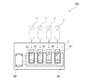
- FIG. 1 is a conceptual view of an image forming apparatus 100.
- the image forming apparatus 100 is an electrophotographic printer. Examples of the image forming apparatus 100 include a laser printer or an LED printer.
- the image forming apparatus 100 includes four developing cartridges 1 and a drawer unit 90.
- the drawer unit 90 is a frame to which four developing cartridges 1 can be attached.
- the image forming apparatus 100 is configured to form an image on the recording surface of a printing sheet by the developer (for example, toner) supplied from the four developing cartridges 1.
- FIG. 2 is a perspective view of the drawer unit 90 and the developing cartridge 1.
- the four developer cartridges 1 are individually replaceable with respect to the drawer unit 90.
- the drawer unit 90 is pulled out from an opening (not shown) formed in the main body of the image forming apparatus 100. Then, in the four slots 91 provided in the drawer unit 90, the developing cartridge 1 is removed and mounted, respectively.
- the drawer unit 90 includes four photosensitive drums (not shown). The photosensitive drum is located near the bottom of each of the four slots 91. The photosensitive drum is rotatable about a rotation axis extending in a second direction described later.
- the four developer cartridges 1 are attached to one drawer unit 90.
- the four developing cartridges 1 contain developers of different colors (for example, cyan, magenta, yellow, and black).
- the number of developing cartridges 1 mounted to the drawer unit 90 may be one to three, or five or more.
- Each of the four developing cartridges 1 has an IC chip 61 as a storage medium.
- the IC chip 61 is a storage medium capable of reading and writing information.
- the image forming apparatus 100 further includes a control unit 80.
- the control unit 80 is configured of, for example, a circuit board.
- the control unit 80 has a processor such as a CPU and various memories.
- the control unit 80 is configured to execute various processes in the image forming apparatus 100 by the processor operating according to the program.
- FIG. 3 is a perspective view of the developing cartridge 1 of the present embodiment.
- FIG. 4 is an exploded perspective view of the developing cartridge 1.
- the developing cartridge 1 has a casing 10, a developing roller 30, a gear portion 40, and an IC chip assembly 60.
- the casing 10 is a housing that can accommodate a developer that extends in one direction.
- the developing roller 30 is located at the end of the casing 10 in the first direction.
- the developing roller 30 is rotatable about a first axis A1 extending in the second direction.
- the first direction intersects (preferably is orthogonal to) the second direction.
- the developing roller 30 is rotatable about a first axis extending in the second direction.
- a direction intersecting the electrical contact surface 611 of the IC chip 61 described later is referred to as a “third direction”.
- the third direction intersects (preferably is orthogonal to) each of the first direction and the second direction.
- the first direction is also the insertion direction when the developing cartridge 1 is inserted into the drawer unit 90.
- the casing 10 has a developer chamber 12 for containing a developer therein.
- the casing 10 has an opening 13.
- the opening 13 communicates the developer chamber 12 with the outside.
- the opening 13 is located at one end of the casing 10 in the first direction.
- the developing roller 30 is located at the opening 13.
- the developing roller 30 has a roller body 31 and a roller shaft 32.
- the roller body 31 is non-rotatably fixed to the roller shaft 32 extending in the second direction. Further, one end of the roller shaft 32 in the second direction is non-rotatably fixed to a developing roller gear 42 described later. Therefore, when the developing roller gear 42 rotates, the roller shaft 32 also rotates, and the roller main body 31 also rotates with the roller shaft 32.
- the developing cartridge 1 has a supply roller whose illustration is omitted.
- the developer When the developing cartridge 1 receives the driving force, the developer is supplied from the developer chamber 12 in the casing 10 to the outer peripheral surface of the developing roller 30 through the supply roller. At this time, the developer is frictionally charged between the supply roller and the developing roller 30. On the other hand, a bias voltage is applied to the roller shaft 32 of the developing roller 30. For this reason, the developer is attracted to the outer peripheral surface of the roller body 31 by the electrostatic force between the roller shaft 32 and the developer.
- the developing cartridge 1 has a layer thickness regulating blade whose illustration is omitted.
- the layer thickness regulating blade is configured to make the developer supplied to the outer peripheral surface of the roller main body 31 have a constant thickness. Thereafter, the developer on the outer peripheral surface of the roller body 31 is supplied to the photosensitive drum provided in the drawer unit 90. At this time, the developer moves from the roller main body 31 to the photosensitive drum in accordance with the electrostatic latent image formed on the outer peripheral surface of the photosensitive drum. Thereby, the electrostatic latent image is visualized on the outer peripheral surface of the photosensitive drum.
- the casing 10 has an outer surface 11 at one end in the second direction.
- Gear portion 40 and IC chip assembly 60 are provided on outer surface 11.
- the gear portion 40 is provided on the outer surface 11 movably with respect to the IC chip assembly 60 in the first direction and the third direction together with the casing 10 as described later.
- the IC chip assembly 60 is provided on the outer surface 11 so as to be movable in the first and third directions with respect to the casing 10 and the gear portion 40. That is, the coupling 41 described later is provided on the outer surface 11 movably with respect to the IC chip assembly 60 in the first and third directions together with the casing 10.
- the IC chip assembly 60 is provided on the outer surface 11 so as to be movable in the first and third directions with respect to the casing 10 and the coupling 41.
- the gear portion 40 has a coupling 41, a developing roller gear 42, an idle gear 43, an agitator gear 44, and a first cover 45, as shown in FIG. In each of the drawings, illustration of a plurality of gear teeth of each gear is omitted.
- the coupling 41 is a member that first receives the driving force supplied from the image forming apparatus 100.
- the coupling 41 is rotatable about a second axis A2 extending in the second direction.
- the coupling 41 has a fastening hole 411.
- the fastening hole 411 is a recess that is recessed in the second direction.
- a coupling gear 412 is rotatably provided on the outer surface 11 of the casing 10 about the second axis A2.
- On the outer peripheral portion of the coupling gear 412 On the outer peripheral portion of the coupling gear 412, a plurality of gear teeth are provided at equal intervals along the entire circumference.
- the coupling 41 rotates with the coupling gear 412 about the second axis A2.
- the coupling 41 and the coupling gear 412 may be integrally formed of resin, or may be separate parts. In the present embodiment, the coupling 41 and the coupling gear 412 are integrally formed.
- a drive shaft (not shown) of the image forming apparatus 100 is inserted into the fastening hole 411 of the coupling 41.
- the drive shaft and the coupling 41 are non-rotatably coupled. Therefore, when the drive shaft rotates, the coupling 41 rotates. Then, the coupling gear 412 also rotates with the coupling 41.
- the developing roller gear 42 is a gear for rotating the developing roller 30.
- the developing roller gear 42 can rotate about a first axis A1 extending in the second direction.
- On the outer peripheral portion of the developing roller gear 42 a plurality of gear teeth are provided at equal intervals over the entire circumference. At least some of the gear teeth of the coupling gear 412 mesh with at least some of the gear teeth of the developing roller gear 42.
- the developing roller gear 42 is non-rotatably fixed to the end of the roller shaft 32 of the developing roller 30 in the second direction. Therefore, when the coupling gear 412 rotates, the developing roller gear 42 rotates. Then, the developing roller 30 also rotates with the developing roller gear 42.
- the idle gear 43 is a gear for transmitting the rotation of the coupling gear 412 to the agitator gear 44.
- the idle gear 43 can rotate about a rotational axis extending in the second direction.
- the coupling gear 412 rotates
- the idle gear 43 rotates.
- the agitator gear 44 also rotates.
- the agitator gear 44 is a gear for rotating the agitator 20 in the developer chamber 12.
- the agitator 20 has an agitator shaft 21 and an agitation blade 22.
- the agitator shaft 21 has a rotational axis extending in the second direction, and can rotate about the rotational axis.
- the stirring blade 22 spreads radially outward from the agitator shaft 21.
- the stirring blade 22 is disposed in the developer chamber 12 of the casing 10.
- An agitator gear 44 is connected to an end of the agitator shaft 21 in the second direction. Therefore, the agitator shaft 21 and the stirring blade 22 rotate together with the agitator gear 44. When the stirring blade 22 rotates, the developer in the developer chamber 12 is stirred.
- the agitator gear 44 can rotate about a rotational axis extending in the second direction. On the outer peripheral portion of the agitator gear 44, a plurality of gear teeth are provided at equal intervals over the entire circumference. When power is transmitted from the coupling 41 to the agitator gear 44 via the idle gear 43, the agitator gear 44 rotates. Then, the agitator 20 rotates with the agitator gear 44.
- a first cover 45 is fixed to the outer surface 11 of the casing 10, for example by at least one screw.
- the coupling gear 412, the developing roller gear 42, the idle gear 43 and the agitator gear 44 are accommodated in the space between the outer surface 11 and the first cover 45.
- the first cover 45 has a through hole 451 penetrating in the second direction.
- the fastening hole 411 of the coupling 41 is exposed to the outside through the through hole 451 of the first cover 45.
- the first cover 45 doubles as a holder cover for holding an IC chip holder 62 of an IC chip assembly 60 described later.
- the IC chip assembly 60 is disposed on the outer surface 11 of the casing 10 and is held by the first cover 45.
- the IC chip assembly 60 has an IC chip 61 which is a storage medium, and an IC chip holder 62 for holding the IC chip 61.
- the IC chip 61 various information related to the developing cartridge 1 is recorded.
- the IC chip 61 has an electrical contact surface 611.
- the electrical contact surface 611 is made of metal which is a conductor.
- the IC chip 61 is fixed to the outer surface 62A of the IC chip holder 62 in the third direction. However, only the electrical contact surface 611 may be fixed to the outer surface 62A of the IC chip holder 62, and the circuit of the IC chip 61 may be provided at another position.
- the drawer unit 90 has an electrical connector whose illustration is omitted.
- the electrical connector is made of metal, for example.
- the electrical contact surface 611 contacts the electrical connector of the drawer unit 90.
- the image forming apparatus 100 can perform at least one of reading of information from the IC chip 61 and writing of information to the IC chip 61.
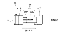
- FIG. 5A is a view of the IC chip assembly 60 viewed from the second direction.
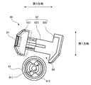
- FIG. 5B is a view of the IC chip assembly 60 as viewed from the first direction.
- FIG. 6 is a view showing an initial position and a contracted position of the first holder 621 when the IC chip holder 62 is in the first position.
- the IC chip holder 62 has a first holder 621, a second holder 622, and a connecting portion 623.
- the first holder 621 and the second holder 622 are arranged in the third direction.
- the connecting portion 623 extends in the third direction.
- the first holder 621 and the second holder 622 are connected by a connecting portion 623. That is, the first holder 621 and the second holder 622 are separated in the third direction.
- the first holder 621 has an outer surface 62A for holding the IC chip 61 (see FIG. 4).
- the connecting portion 623 is a first connecting portion 623A extending in the third direction from the first holder 621 toward the second holder 622, and a second connecting portion extending in the third direction from the second holder 622 toward the first holder 621. And 623 B. That is, the connecting portion 623 is configured by combining the first connecting portion 623A and the second connecting portion 623B.
- the first holder 621 and the first connecting portion 623A may be integrally formed.
- the second holder 622 and the second connecting portion 623B may be integrally formed.
- the first connection portion 623A When the first connection portion 623A is fitted into the second connection portion 623B, the first connection portion 623A can move in the third direction along the second connection portion 623B. Thereby, the first holder 621 can move in the third direction with respect to the second holder 622.
- the connecting portion 623 has the same length in the first direction at any position in the third direction.
- the length of the connecting portion 623 in the first direction is represented by L1.
- the length in the first direction of the first holder 621 in a portion facing the second holder 622 in the third direction is represented by L2.
- the length in the first direction of the second holder 622 in a portion facing the first holder 621 is represented by L3.
- the length L1 is shorter than the length L2 and the length L3. Since the length L1 is shorter than the length L2 and the length L3, a space 64 (see FIG. 5A) is provided between the first holder 621 and the second holder 622 and around the connecting portion 623. is there.
- the IC chip assembly 60 further includes a coil spring 63.
- the coil spring 63 is an elastically deformable member that expands and contracts in a third direction between the first state and the second state. That is, the coil spring 63 is elastically deformable in the third direction between the first state and the second state.
- the coil spring 63 is disposed between the first holder 621 and the second holder 622.
- the first holder 621 moves in the third direction with respect to the second holder 622 in accordance with elastic deformation (specifically, expansion and contraction) of the coil spring 63.
- the connecting portion 623 has a hollow internal space extending in the third direction, and the coil spring 63 is disposed in the hollow of the connecting portion 623.
- the length in the third direction of the coil spring 63 in the first state is longer than the length in the third direction of the coil spring 63 in the second state.
- the coil spring 63 in the second state is contracted more than the natural length.
- the position in the third direction of the first holder 621 with respect to the second holder 622 in the first state in which the coil spring 63 is in the first state will be referred to as “initial position (an example of third position and one position)”.
- the position in the third direction of the first holder 621 with respect to the second holder 622 in the second state of the coil spring 63 is referred to as “contraction position (an example of the fourth position and another position)”.
- the first holder 621 is located at the contracted position when the coil spring 63 is in the second state, and is located at the initial position when the coil spring 63 is in the first state. That is, the first holder 621 can move in the third direction between the initial position and the contracted position with respect to the second holder 622 as the coil spring 63 expands and contracts.
- the position of the first holder 621 indicated by the solid line is the initial position
- the position of the first holder 621 indicated by the two-dot chain line is the contracted position.
- the IC chip assembly 60 configured in this manner is held by the first cover 45 on the outer surface 11 of the casing 10.
- the first cover 45 has an opening 452 penetrating in the third direction.
- the IC chip assembly 60 is held by the first cover 45 by inserting the connecting portion 623 (the first connecting portion 623A and the second connecting portion 623B) of the IC chip holder 62 into the opening 452.
- the length in the first direction of the opening 452 of the first cover 45 is shorter than the length L2 in the first direction of the first holder 621 and the length L3 in the first direction of the second holder 622. Therefore, the IC chip assembly 60 in which the connecting portion 623 is inserted into the opening 452 does not fall off the first cover 45.
- the length in the first direction of the opening 452 of the first cover 45 is longer than the length L1 in the first direction of the connecting portion 623. For this reason, the first holder 621 and the second holder 622 can move in the first direction with respect to the casing 10, the coupling 41 and the first cover 45.
- the first holder 621 moves toward the second holder 622.
- the second holder 622 abuts on the drawer unit 90, movement in a direction away from the first holder 621 in the third direction is prevented.
- the coil spring 63 contracts.
- the second holder 622 maintains the contact with the drawer unit 90, and the first holder 621 receives the third force by the restoring force (elastic force) of the coil spring 63. It moves away from the second holder 622 in the direction.
- the electrical contact surface 611 is pressed against the electrical connector of the drawer unit 90, and the electrical contact surface 611 and the electrical connector are in contact and maintained in contact.
- the image forming apparatus 100 also has a contact state and a separation state.
- the contact state the contact between the developing roller 30 and the photosensitive drum is maintained while the contact between the electrical contact surface 611 and the electrical connector is maintained.
- the separated state the image forming apparatus 100 separates the developing roller 30 and the photosensitive drum from each other.
- the image forming apparatus 100 operates in either a contact state or a separation state.
- the casing 10, the coupling 41, and the first cover 45 are in a state where the contact between the electrical contact surface 611 and the electrical connector is maintained. Move in one direction. Therefore, when the image forming apparatus 100 changes between the separated state and the contact state, the casing 10, the coupling 41 and the first cover 45 move in the first direction with respect to the IC chip holder 62.
- first position the position of the IC chip holder 62 with respect to the casing 10 and the first cover 45 in the contact state of the image forming apparatus 100
- second position the position of the IC chip holder 62 with respect to the casing 10 and the first cover 45 in the separated state of the image forming apparatus 100
- the second position is closer to the developing roller 30 than the first position.
- the first cover 45 has the through hole 451 into which the coupling 41 is inserted.
- the opening 452 and the through hole 451 are provided side by side in the first direction. That is, the IC chip assembly 60 is attached to the first cover 45 with the IC chip assembly 60 and the coupling 41 aligned in the first direction, and the fastening hole 411 of the coupling 41 is of the first cover 45. It is exposed from the through hole 451.
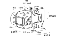
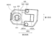
- FIG. 7 is a view of the outer surface 11 of the developing cartridge 1 viewed from the second direction.
- FIG. 7 is a view in which the first cover 45 is omitted. Further, FIG. 7 shows a state in which the IC chip holder 62 is in the first position.
- FIG. 8 is a view showing the positional relationship between the IC chip holder 62 and the coupling 41 when the IC chip holder 62 is in the first position and in the second position.
- the upper drawing of FIG. 8 shows the case where the IC chip holder 62 is at the second position, and the lower drawing of FIG. 8 shows the case where the IC chip holder 62 is at the second position.
- the first holder 621 is at the initial position.
- the IC chip assembly 60 and the coupling 41 are arranged side by side in the first direction.
- a part of the coupling 41 is located between the first holder 621 and the second holder 622 in the third direction, and located apart from the connecting portion 623 in the first direction. That is, part of the coupling 41 is located in the space 64 between the first holder 621 and the second holder 622.
- the coupling 41 is positioned between the first holder 621 and the second holder 622 in the third direction, and the first holder 621 and the second holder 622 and the coupling 41 are partially in the first direction. Overlap.
- the first holder 621 and the second holder 622 and the coupling 41 can be brought close to each other in the first direction.
- the developing cartridge 1 can be miniaturized, and the downsizing of the image forming apparatus 100 to which the developing cartridge 1 is mounted can also be realized.
- the coupling 41 can be positioned in the space 64 (see FIG. 6). That is, the length in the third direction between the first holder 621 in the contracted position and the second holder 622 is longer than the length in the third direction of a portion of the coupling 41 located in the space 64. Therefore, even if the coupling 41 enters the space 64 of the IC chip assembly 60 in the first direction as shown in FIG. 7, the coupling 41, the first holder 621 and the second holder 622 are There is no interference with one another.
- the coupling 41 is positioned between the first holder 621 and the second holder 622 in the third direction, and the first holder The first holder 621 and the second holder 622 partially overlap the coupling 41 in the first direction. Therefore, the first holder 621 and the second holder 622 and the coupling 41 can be brought close to each other in the first direction. As a result, the developing cartridge 1 can be miniaturized.
- the part of the coupling 41 may be positioned in the space 64 between the first holder 621 and the second holder 622 only when the IC chip holder 62 is in the second position. That is, in the contact state of the image forming apparatus 100 in which the IC chip holder 62 is at the first position, a part of the coupling 41 is not located in the space 64 between the first holder 621 and the second holder 622. Even in this case, at least in the separated state of image forming apparatus 100 in which IC chip holder 62 is at the second position, coupling 41 is interposed between first holder 621 and second holder 622 in the third direction. The first holder 621 and the second holder 622 and the coupling 41 partially overlap in the first direction. Therefore, the first holder 621 and the second holder 622 and the coupling 41 can be brought close to each other in the first direction.
- Embodiment 2 the developing cartridge 2 according to the second embodiment of the present invention will be described with reference to FIGS. 9 to 11.
- the same members as those of the developing cartridge 1 of the first embodiment are denoted by the same reference numerals, and the description thereof is omitted.
- the structure for miniaturizing the developing cartridge 2 in the first direction is different from the developing cartridge 1 of the first embodiment.
- the IC chip holder 62 of the first embodiment has the space 64 shown in FIG. 5A, whereas the IC chip holder 65 of the present embodiment does not have the space 64.
- the coupling 41 of the first embodiment is provided on the outer surface 11 of the developing cartridge 1 and is integrally formed with the coupling gear 412
- the coupling 141 of the present embodiment is different from the coupling gear 412 and the coupling gear 412. It is separately formed, and is disposed apart from the outer surface 11 of the developing cartridge 2 in the second direction.
- the IC chip holder 65 is positioned between the coupling 141 and the coupling gear 412 in the second direction.
- FIG. 9 is a perspective view of the developing cartridge 2 of the present embodiment.
- FIG. 10 is an exploded perspective view of the developing cartridge 2.
- the coupling 141 is disposed away from the outer surface 11 in the second direction, as shown in FIG.
- Coupling gear 412 is rotatably supported on outer surface 11. That is, the coupling gear 412 is rotatable relative to the outer surface 11.
- the coupling 141 and the coupling gear 412 are spaced apart in the second direction.
- the developer cartridge 2 further has a shaft 413 extending in the second direction from the coupling 141 toward the coupling gear 412.
- the shaft shaft 413 couples the coupling 141 and the coupling gear 412.
- the coupling gear 412 rotates with the coupling 141 via the shaft shaft 413.
- the coupling 141 is rotatable about a second axis A2 extending in the second direction.
- the coupling 141, the coupling gear 412 and the shaft shaft 413 may be separate parts or may be integrally formed. In the present embodiment, the coupling 141 and the shaft shaft 413 are integrally formed.
- the shaft axis 413 has a cylindrical shape.
- the outer diameter of the shaft shaft 413 is smaller than the outer diameter of each of the coupling 141 and the coupling gear 412.
- the outer diameter of the coupling gear 412 may be the diameter excluding the gear teeth (diameter of the bottom circle) or the diameter including the gear teeth (diameter of the tip circle).
- a space may be formed at least between the coupling 141 and the coupling gear 412 and around the shaft axis 413.
- the IC chip assembly 60 has an IC chip holder 65. Similar to the IC chip holder 62 of the first embodiment, the IC chip holder 65 is movable to the first position and the second position.
- the IC chip holder 65 has a first holder 651, a second holder 652, and a connecting portion 653.
- the first holder 651 and the second holder 652 are non-removably combined via the connecting portion 653. That is, the first holder 651 and the second holder 652 are located apart in the third direction.
- the first holder 651 and the second holder 652 are movable in the first direction and the third direction with respect to the casing 10 and the coupling 141.
- the first holder 651 is movable in the third direction with respect to the second holder 652.
- the first holder 651 has an outer surface 65 A for holding the IC chip 61.
- the connecting portion 653 is a cylindrical first connecting portion 651A extending in the third direction from the first holder 651 to the second holder 652, and a cylinder extending in the third direction from the second holder 652 to the first holder 651.
- a second connecting portion 652A a cylindrical first connecting portion 651A extending in the third direction from the first holder 651 to the second holder 652, and a cylinder extending in the third direction from the second holder 652 to the first holder 651.
- a second connecting portion 652A The first holder 651 and the first connecting portion 651A may be integrally formed.
- the second holder 652 and the second connecting portion 652A may be integrally formed.
- the inner diameter of the first connecting portion 651A is larger than the outer diameter of the second connecting portion 652A, and the second connecting portion 652A can be inserted inside the first connecting portion 651A.
- the inner diameter of the second connection portion 652A is larger than the outer diameter of the coil spring 63, and the coil spring 63 can be accommodated inside the first connection portion 651A and the second connection portion 652A.
- the coil spring 63 is accommodated inside the first connecting portion 651A and the second connecting portion 652A in a state at least shorter than the natural length.
- the first holder 651 is located at the contracted position (the fourth position and an example of another position) when the coil spring 63 is in the second state, and at the initial position (when the coil spring 63 is in the first state). Position in the third position and one position). That is, with the elastic deformation (specifically, expansion and contraction) of the coil spring 63, the first holder 651 is movable in the third direction with respect to the second holder 652 between the initial position and the contracted position.
- the first holder 651 has a through hole 651B penetrating in the second direction.
- the shaft shaft 413 is inserted into the through hole 651B.
- the length between the coupling 141 and the coupling gear 412 in the second direction is longer than the length in the second direction of the first holder 651.
- the first holder 651 is located between the coupling 141 and the coupling gear 412. That is, the coupling 141 and the coupling gear 412 are held by the first holder 651 in a state where the shaft shaft 413 is inserted into the through hole 651B. Then, in a state in which the shaft shaft 413 is inserted into the through hole 451 of the first cover 145, the IC chip holder 65 is sandwiched and held between the first cover 145 and the outer surface 11.
- the lengths in the first direction and the third direction of the through hole 651 B of the first holder 651 are larger than the outer diameter of the shaft shaft 413 and smaller than the outer diameters of the coupling 141 and the coupling gear 412.
- the first holder 651 can move in the first direction and the third direction with respect to the coupling 141 and the coupling gear 412.
- the first holder 651 can move in the third direction with respect to the second holder 652 in accordance with elastic deformation (specifically, expansion and contraction) of the coil spring 63.
- the image forming apparatus 100 can operate in either a contact state where the developing roller 30 and the photosensitive drum contact or a separated state where the developing roller 30 and the photosensitive drum are separated from each other.
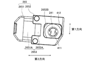
- FIG. 11 is a view of the outer surface 11 of the developing cartridge 2 as viewed from the second direction.
- FIG. 11 is a view in which the first cover 145 is omitted.
- the IC chip assembly 60 and the coupling 141 are arranged side by side in the first direction. Also, by inserting the shaft shaft 413 into the through hole 651 B of the first holder 651, a part of the coupling 141 is positioned between the first holder 651 and the second holder 652 in the third direction. . Since the shaft shaft 413 is inserted into the through hole 651 B of the first holder 651, a part of the coupling 141 is in the third direction, regardless of whether the IC chip holder 65 is in the first position or the second position. It is located between the first holder 651 and the second holder 652.
- the coupling 141 is positioned between the first holder 651 and the second holder 652 in the third direction, and the first holder 651 and the second holder 652 and the coupling 141 are in the first direction. And in the third direction. That is, the first holder 651 and the second holder 652 and the coupling 141 are disposed in positions adjacent to each other in the first direction and the third direction. Furthermore, since the shaft shaft 413 connected to the coupling 141 is inserted into the through hole 651 B of the first holder 651, the first holder 651 and the second holder 652 and the coupling 141 approach each other also in the second direction. Placed in position. As a result, the developing cartridge 2 can be miniaturized.
- Embodiment 3 the developing cartridge of Embodiment 3 of the present invention will be described with reference to FIGS. 12 and 13.
- FIG. in the third embodiment the same members as those of the developing cartridge 1 of the first embodiment and the developing cartridge 2 of the second embodiment are designated by the same reference numerals, and the description thereof will be omitted.
- the third embodiment is common to the second embodiment in that the first holder 1651 is provided with a hole 1651C penetrating in the second direction and the coupling 241 is inserted into the hole 1651C.
- a part of the coupling 141 is located between the first holder 651 and the second holder 652, but in the third embodiment, a part of the coupling 241 is the first holder It is located in 1651.
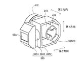
- FIG. 12 is a perspective view of the IC chip holder 165 and the coupling 241 of the developing cartridge of the third embodiment.
- FIG. 13 is a view of the IC chip holder 165 and the coupling 241 of FIG. 12 as viewed from the second direction.
- the coupling 241 has a cylindrical shape extending in the second direction. At one end of the coupling 241 in the second direction, a fastening hole 411 (recess) recessed in the second direction is provided. Further, the other end of the coupling 241 in the second direction is connected to the coupling gear 412. Then, the coupling 241 rotates with the coupling gear 412 about a second axis extending in the second direction.
- the coupling 241 and the coupling gear 412 may be separate parts or may be integrally formed.
- the IC chip assembly 60 has an IC chip holder 165. Similar to the IC chip holder 65 of the second embodiment, the IC chip holder 165 includes a first holder 1651, a second holder 1652, and a connecting portion 1653.
- the first holder 1651 is movable in the third direction with respect to the second holder 1652.
- the connecting portion 1653 is a cylindrical first connecting portion 1651 A extending in the third direction from the first holder 1651 toward the second holder 1652, and in the third direction from the second holder 1652 toward the first holder 1651.
- an extending cylindrical second connecting portion 1652A is integrally formed.
- the second holder 1652 and the second connecting portion 1652A may be integrally formed.
- the first connecting portion 1651A and the second connecting portion 1652A are arranged side by side in the third direction. That is, the first holder 1651 and the second holder 1652 are located apart in the third direction.
- the coil spring 63 is accommodated inside the first connection portion 1651A and the second connection portion 1652A.
- the first holder 1651 moves in the third direction with respect to the second holder 1652 in accordance with elastic deformation (specifically, expansion and contraction) of the coil spring 63.
- the first holder 1651 has a through hole 1651C penetrating in the second direction.
- the coupling 241 is inserted into the through hole 1651C.
- the lengths in the first direction and the third direction of the through holes 1651 C are larger than the outer diameter of the coupling 241.
- the initial position an example of the third position and one position
- the contracted position with respect to the second holder 1652 It is movable in the third direction between the fourth position and an example of another position).
- the first holder 1651 and the second holder 1652 overlap the coupling 241 in the first direction. That is, the first holder 1651 and the second holder 1652 and the coupling 241 are disposed in positions adjacent to each other in the first direction. As a result, the developing cartridge can be miniaturized in the first direction. Further, since the coupling 241 is inserted into the through hole 1651 C of the first holder 1651, the developing cartridge can be further miniaturized in the second direction and the third direction.
- the structure for miniaturizing the developing cartridge in the first direction is not limited to the above.
- the first modification is a modification of the third embodiment.
- symbol is attached
- the through hole 1651 C in which the coupling 241 is inserted is provided in the first holder 1651, but the through hole may be provided in the second holder 1652.
- a configuration in which a through hole 2652 B for inserting the coupling 241 is provided in the second holder 2652 will be described.
- FIG. 14 is a perspective view of the IC chip holder 265 and the coupling 241 when the coupling 241 is positioned in the second holder 2652.
- FIG. 15 is a view of the IC chip holder 265 and the coupling 241 of FIG. 14 as viewed from the second direction.
- the IC chip holder 265 has a first holder 2651, a second holder 2652, and a connecting portion 2653.
- the connecting portion 2653 is a cylindrical first connecting portion 2651 A extending in the third direction from the first holder 2651 to the second holder 2652, and a cylinder extending in the third direction from the second holder 2652 toward the first holder 2651.
- a second connecting portion 2652A a second connecting portion 2652A.
- the first holder 2651 and the second holder 2652 are spaced apart in the third direction.
- the first connecting portion 2651A may be integrally formed with the first holder 2651.
- the second connecting portion 2652A may be integrally formed with the second holder 2652.
- the second holder 2652 is provided with a through hole 2652B penetrating in the second direction.
- the coupling 241 is inserted into the through hole 2652B.
- the lengths in the first direction and the third direction of the through holes 2652 B are larger than the outer diameter of the coupling 241.
- the first holder 2651 and the second holder 2652 are the casing 10 in a state where the coupling 241 is inserted into the through hole 2652B.
- the coupling 241 can be moved in the first direction and the third direction. With the coupling 241 inserted in the through hole 2652B, the first holder 2651 and the second holder 2652 are movable to the first position and the second position.
- the first holder 2651 is an initial position (an example of the third position and one position) and a contracted position (the third position and one position) with respect to the second holder 2652 in accordance with elastic deformation (specifically, expansion and contraction) of the coil spring 63. It is movable in the third direction between the fourth position and an example of another position).
- the first holder 2651 and the second holder 2652 overlap the coupling 241 in the first direction. That is, the first holder 2651 and the second holder 2652 and the coupling 241 are disposed in positions adjacent to each other in the first direction. As a result, the developing cartridge can be miniaturized in the first direction. Further, since the coupling 241 is inserted into the through hole 2652 B of the second holder 2652, the developing cartridge can be further miniaturized in the second and third directions.
- the first holder 1651 (2651) and the second holder 1652 (2652) are not limited to the configurations of the third embodiment and the first modification.
- the modification 2 is another modification of the third embodiment.
- the modification 2 about the member same as Embodiment 3, the same numerals are attached and the explanation is omitted.
- FIG. 16 is a perspective view of the IC chip holder 365 and the coupling 241 of the second modification.
- FIG. 17 is a view of the IC chip holder 365 and the coupling 241 of FIG. 16 as viewed from the second direction.
- the second holder 3652 is provided with a through hole 3652C penetrating in the second direction.
- the IC chip holder 365 has a first holder 3651, a second holder 3652, and a connecting portion 3653.
- the first holder 3651 and the second holder 3652 are spaced apart in the third direction.
- a coil spring 63 is accommodated in the connection portion 3653.
- the lengths in the first direction and the third direction of the through holes 3652 C are larger than the outer diameter of the coupling 241.
- the coupling 241 is inserted into the through hole 3652B. Thereby, in a state where the coupling 241 is inserted into the through hole 3652C, the first holder 3651 and the second holder 3652 can move in the first direction and the third direction with respect to the casing 10 and the coupling 241. It becomes. With the coupling 241 inserted in the through hole 3652C, the first holder 3651 and the second holder 3652 are movable to the first position and the second position.
- the first holder 3651 and the second holder 3652 overlap the coupling 241 in the first direction. That is, the first holder 3651 and the second holder 3652 and the coupling 241 are disposed in positions adjacent to each other in the first direction. As a result, the developing cartridge can be miniaturized in the first direction. Further, since the coupling 241 is inserted into the through hole 3652C of the second holder 3652, the developing cartridge can be further miniaturized in the second direction and the third direction.
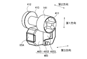
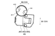
- FIG. 18 is a perspective view of the IC chip holder 465 and the coupling 141 of the third modification.
- FIG. 19 is a view of the IC chip holder 465 and the coupling 141 of FIG. 18 as viewed from the second direction. In FIG. 18 and FIG. 19, the other members of the developing cartridge are omitted.
- the IC chip holder 465 of the third modification has the first holder 4651, the second holder 4652, and the connecting portion 4653.
- the first holder 4651 of the third modification does not have the through hole 651B shown in FIG.
- the first holder 4651 and the second holder 4652 are spaced apart in the third direction.
- the coil spring 63 is housed inside the connection portion 4653.
- the first holder 4651 and the second holder 4652 are movable in the first direction and the third direction with respect to the casing 10 and the coupling 141.
- the first holder 4651 is an initial position (an example of the third position and one position) and a contracted position (the third position and one position) with respect to the second holder 4652 along with elastic deformation (specifically, expansion and contraction) of the coil spring 63. It is movable in the third direction between the fourth position and an example of another position).
- the coupling 141 of the third modification is coupled to the coupling gear 412 by a shaft 413 extending in the second direction toward the coupling gear 412. That is, the coupling 141 is coupled to the coupling gear 412 via the shaft shaft 413.
- the length in the second direction between the coupling 141 and the coupling gear 412 is longer than the length in the second direction of the IC chip holder 465.
- the IC chip holder 465 is located between the coupling 141 and the coupling gear 412. Then, even if the IC chip holder 465 is positioned at either the first position or the second position, a part of the coupling 141 is positioned between the first holder 4651 and the second holder 4652 in the third direction. Do.
- the coupling 141 is positioned between the first holder 4651 and the second holder 4652 in the third direction, and the first holder 4651 and the second holder 4652, the coupling 141 Since the first and second holders 4651 and 4652 and the coupling 141 can be made to approach each other in the first direction, because they partially overlap in the first direction. As a result, the developing cartridge can be miniaturized.
- the IC chip holder 62 of the first embodiment may be combined with the configuration of the coupling 141 and the shaft shaft 413 of the second embodiment.
- a fourth modification will be described with reference to FIGS. 20 and 21.
- the same members as those in the first and second embodiments described above are given the same reference numerals, and descriptions thereof will be omitted.
- FIGS. 20 and 21 are diagrams showing the positional relationship between the IC chip holder 62 of the fourth modification and the coupling 141.
- FIG. 20 and 21 are diagrams showing the positional relationship between the IC chip holder 62 of the fourth modification and the coupling 141.
- the coupling 141 is coupled with the coupling gear 412 via the shaft shaft 413 as in the second embodiment.
- the shaft shaft 413 is positioned in the space 64 of the IC chip holder 62, a part of the coupling 141 is the first holder regardless of whether the IC chip holder 62 is positioned at either the first position or the second position. 621 and a second holder 622. Whether the IC chip holder 62 is located at the first position or the second position, the shaft shaft 413 is in a state where a part of the coupling 141 is located between the first holder 621 and the second holder 622 , And separated from the connecting portion 623.
- the coupling 141 can be disposed closer to the IC chip holder 62 in the first direction, as compared with the first embodiment. Therefore, as compared with Embodiment 1, the coupling 141 can be arranged such that the first holder 621 and the second holder 622 and the coupling 141 have a large overlap in the first direction. As a result, as compared with the first embodiment, the first holder 621 and the second holder 622 and the coupling 141 can be further brought closer to each other in the first direction.
- the coil spring 63 is used as the elastic member.
- another type of spring such as a leaf spring or a torsion spring may be used as the elastic member.
- the elastic member may be, for example, rubber.
- the coil spring 63 was comprised so that it could expand-contract.
- the elastic member may be configured only to expand as long as it elastically deforms, or may be configured only to contract. Note that "the elastic member is elastically deformable” means that the elastic member is stretchable, shrinkable, or stretchable. That is, the elastic member is configured to expand or contract in the third direction between the first state and the second state, or to expand and contract.
- the elastic member is configured to change its length in the third direction between the first state and the second state.
- the elastic member has any one of the extensibility that extends in the third direction, the contractility that contracts in the third direction, and the stretchability that expands and contracts in the third direction, whereby the first member It is configured to change between the state and the second state.
- the IC chip 61 having the electrical contact surface 611 is fixed to the outer surface of the IC chip holder (first holder).
- the electrical contact surface in contact with the electrical connector may be fixed to the outer surface of the first holder, and the portion other than the electrical contact surface of the IC chip may be disposed at another location of the developing cartridge. .
Landscapes
- Physics & Mathematics (AREA)
- General Physics & Mathematics (AREA)
- Engineering & Computer Science (AREA)
- Computer Vision & Pattern Recognition (AREA)
- Electrophotography Configuration And Component (AREA)
- Dry Development In Electrophotography (AREA)
Abstract
現像カートリッジを小型化できる構造を提供することを目的とする。現像剤を収容可能なケーシング10に対して、第1方向に移動可能で、電気的接触面611を保持する第1ホルダ621と、ケーシング10に対して第1方向に、第1ホルダ621と共に移動可能であって、第3方向について、第1ホルダ621と離れて位置する第2ホルダ622と、第2方向に延びる第2軸について回転可能なカップリング41と、を備える。第1ホルダ621と第2ホルダ622とは、ケーシング10およびカップリング41に対して、第1方向における第1位置と、第2位置との間で移動可能であり、第1ホルダ621と第2ホルダ622が第2位置の場合、カップリング41の一部は、第1ホルダ621と第2ホルダ622との間に位置する。
Description
本発明は、現像カートリッジに関する。
従来、レーザプリンタ、LEDプリンタ等の電子写真方式の画像形成装置が知られている。画像形成装置には、現像カートリッジが用いられる。現像カートリッジは、トナーを供給するための現像ローラを有する。特許文献1に記載の現像カートリッジは、ドロアユニットに対して装着される。ドロアユニットは、画像形成装置の内部に収容され、画像形成装置から引き出される。ドロアユニットは、感光ドラムを有する。ドロアユニットに現像カートリッジが装着されると、感光ドラムと現像ローラとが向かい合う。
また、特許文献2に記載の現像カートリッジは、ドラムカートリッジに対して装着される。ドラムカートリッジは、感光ドラムを有する。ドラムカートリッジに現像カートリッジが装着されると、感光ドラムと現像ローラとが向かい合う。そして、現像カートリッジがドラムカートリッジに装着された状態で、現像カートリッジは、画像形成装置に装着される。
また、従来、記憶媒体を有する現像カートリッジも知られている。記憶媒体は、例えば、ICチップである。記憶媒体は電気的接触面を有する。現像カートリッジは、記憶媒体を保持するホルダを有している。また、現像カートリッジは、カップリングを有している。例えば、カップリングと、ホルダとが、カートリッジの側面に並んで配置される場合、現像カートリッジが大型化するおそれがある。
本発明は、現像カートリッジを小型化できる構造を提供することを目的とする。
上記課題を解決するため、本願の第1発明は、現像カートリッジであって、現像剤を収容可能な筐体と、第1方向における前記筐体の端部に位置する現像ローラであって、第2方向に延びる第1軸について回転可能な現像ローラと、電気的接触面を有する記憶媒体と、前記筐体に対して、前記第1方向に移動可能な第1ホルダであって、外表面に前記電気的接触面を保持する第1ホルダと、前記筐体に対して前記第1方向に、前記第1ホルダと共に移動可能な第2ホルダであって、前記電気的接触面に交差する第3方向について、前記第1ホルダと離れて位置する第2ホルダと、前記第2方向に延びる第2軸について回転可能なカップリングであって、前記現像ローラと共に回転可能なカップリングと、を備え、前記第1ホルダと前記第2ホルダとは、前記筐体および前記カップリングに対して、前記第1方向における第1位置と、前記第1方向における第2位置であって、前記第1位置よりも前記現像ローラの近くに位置する第2位置との間で移動可能であり、前記第1ホルダと前記第2ホルダが前記第2位置の場合、前記カップリングの一部は、前記第1ホルダと前記第2ホルダとの間に位置する。
本願の第2発明は、第1発明の現像カートリッジであって、前記第1ホルダと前記第2ホルダとの間に位置する弾性部材であって、第1状態と第2状態との間で前記第3方向に伸張および/または収縮可能であり、前記第1状態における前記第3方向の長さは、前記第2状態における前記第3方向の長さよりも長い弾性部材を備え、前記第1ホルダは、前記弾性部材の伸張および/または収縮に伴い、前記第2ホルダに対して、第3位置と第4位置との間で前記第3方向に移動可能であり、前記弾性部材が前記第1状態のときに、前記第1ホルダは前記第3位置に位置し、前記弾性部材が前記第2状態のときに、前記第4位置に位置する。
本願の第3発明は、第1発明または第2発明の現像カートリッジであって、前記第1ホルダおよび前記第2ホルダが前記第1位置にある場合、前記カップリングの一部が、前記第1ホルダと前記第2ホルダとの間に位置する。
本願の第4発明は、第1発明から第3発明の現像カートリッジであって、前記第3方向に延び、前記第1ホルダと前記第2ホルダとを連結する連結部であって、前記第1方向の長さが前記第1ホルダおよび前記第2ホルダよりも短い連結部を備え、前記第1ホルダと前記第2ホルダが前記第2位置の場合、前記カップリングの一部が前記第1ホルダと前記第2ホルダとの間に位置する状態で、前記カップリングの一部は、前記連結部と離れて位置する。
本願の第5発明は、第4発明の現像カートリッジであって、前記第1ホルダと前記第2ホルダが前記第1位置の場合、前記カップリングの一部が前記第1ホルダと前記第2ホルダとの間に位置する状態で、前記カップリングの一部は、前記連結部と離れて位置する。
本願の第6発明は、第1発明から第3発明の現像カートリッジであって、前記カップリングは、前記第2方向における前記筐体の外表面から、前記第2方向に離れて位置し、前記現像カートリッジは、さらに、前記筐体の前記第1端部に位置し、前記現像ローラと共に回転可能な現像ローラギアと、前記現像ローラギアと噛み合うカップリングギアと、前記第2方向に延びるシャフト軸であって、前記カップリングと前記カップリングギアとを連結するシャフト軸と、を備え、前記シャフト軸の径は、前記カップリングの径および前記カップリングギアの径より短く、前記カップリングと前記カップリングギアとの間に、前記第1ホルダの一部および前記第2ホルダの一部の少なくとも一方が位置することで、前記カップリングの一部が、前記第1ホルダと前記第2ホルダとの間に位置する。
本願の第7発明は、第6発明の現像カートリッジであって、前記第1ホルダおよび前記第2ホルダの一方は、前記第2方向に延びる貫通孔を有し、前記シャフト軸が前記貫通孔に挿入されることで、前記カップリングの一部が、前記第1ホルダと前記第2ホルダとの間に位置する。
本願の第8発明は、第6発明の現像カートリッジであって、前記第3方向に延び、前記第1ホルダと前記第2ホルダとを連結する連結部であって、前記第1方向の長さが前記第1ホルダおよび前記第2ホルダよりも短い連結部、を備え、前記第1ホルダと前記第2ホルダが前記第2位置の場合、前記カップリングの一部が前記第1ホルダと前記第2ホルダとの間に位置する状態で、前記シャフト軸は、前記連結部と離れて位置する。
本願の第9発明は、第8発明の現像カートリッジであって、前記第1ホルダと前記第2ホルダが前記第1位置の場合、前記カップリングの一部が前記第1ホルダと前記第2ホルダとの間に位置する状態で、前記シャフト軸は、前記連結部と離れて位置する。
本願の第10発明は、第1発明から第3発明の現像カートリッジであって、前記第2方向に延びるシャフト軸であって、前記カップリングに連結されるシャフト軸を備え、前記第1ホルダおよび前記第2ホルダの一方は、前記第2方向に延びる貫通孔であって、第1方向および第3方向の長さが、前記シャフト軸の外径よりも長い貫通孔を有し、前記シャフト軸が前記貫通孔に挿入されることで、前記カップリングの一部が、前記第1ホルダと前記第2ホルダとの間に位置する。
本願の第11発明は、現像カートリッジであって、現像剤を収容可能な筐体と、第1方向における前記筐体の端部に位置する現像ローラであって、第2方向に延びる第1軸について回転可能な現像ローラと、電気的接触面を有する記憶媒体と、前記筐体に対して、前記第1方向に移動可能な第1ホルダであって、外表面に前記電気的接触面を保持する第1ホルダと、前記筐体に対して前記第1方向に、前記第1ホルダと共に移動可能な第2ホルダであって、前記電気的接触面に交差する第3方向について、前記第1ホルダと離れて位置する第2ホルダと、前記第2方向に延びる第2軸について回転可能なカップリングであって、前記現像ローラと共に回転可能なカップリングと、を備え、前記第1ホルダと前記第2ホルダのいずれかは、前記第2方向に延びる貫通孔を有し、前記カップリングが前記貫通孔に挿入された状態で、前記第1ホルダと前記第2ホルダとは、前記筐体および前記カップリングに対して前記第1方向に移動可能である。
本願の第12発明は、第11発明の現像カートリッジであって、前記第1ホルダと前記第2ホルダとは、前記筐体および前記カップリングに対して、前記第1方向における第1位置と、前記第1方向における第2位置であって、前記第1位置よりも前記現像ローラの近くに位置する第2位置との間で移動可能である。
本願の第13発明は、第11発明または第12発明の現像カートリッジであって、前記第1ホルダと前記第2ホルダとの間に位置する弾性部材であって、第1状態と第2状態との間で前記第3方向に伸張および/または収縮可能であり、前記第1状態における前記第3方向の長さは、前記第2状態における前記第3方向の長さよりも長い弾性部材を備え、前記第1ホルダは、前記弾性部材の伸張および/または収縮に伴い、前記第2ホルダに対して、第3位置と第4位置との間で前記第3方向に移動可能であり、前記弾性部材が前記第1状態のときに、前記第1ホルダは前記第3位置に位置し、前記弾性部材が前記第2状態のときに、前記第4位置に位置する。
本願の第14発明は、現像カートリッジであって、現像剤を収容可能な筐体と、第1方向における前記筐体の端部に位置する現像ローラであって、第2方向に延びる第1軸について回転可能な現像ローラと、電気的接触面を有する記憶媒体と、前記筐体に対して、前記第1方向に移動可能な第1ホルダであって、外表面に前記電気的接触面を保持する第1ホルダと、前記筐体に対して前記第1方向に、前記第1ホルダと共に移動可能な第2ホルダであって、前記電気的接触面に交差する第3方向について、前記第1ホルダと離れて位置する第2ホルダと、前記第2方向に延びる第2軸について回転可能なカップリングであって、前記現像ローラと共に回転可能なカップリングと、前記第1ホルダと前記第2ホルダとの間に位置する弾性部材であって、第1状態と第2状態との間で前記第3方向に伸張および/または収縮可能であり、前記第1状態における前記第3方向の長さは、前記第2状態における前記第3方向の長さよりも長い弾性部材と、を備え、前記第1ホルダと前記第2ホルダのいずれかは、前記第2方向に延びる貫通孔を有し、前記カップリングが前記貫通孔に挿入された状態で、前記第1ホルダは、前記弾性部材の伸張および/または収縮に伴い、前記第2ホルダに対して、一の位置と他の位置との間で前記第3方向に移動可能であり、前記第1ホルダは、前記弾性部材が前記第1状態のときに、前記一の位置に位置し、前記弾性部材が前記第2状態のときに、前記他の位置に位置する。
本願の第14発明の現像カートリッジの構成は、以下のように表現することもできる。すなわち、現像カートリッジは、現像剤を収容可能な筐体と、第1方向における前記筐体の端部に位置する現像ローラであって、第2方向に延びる第1軸について回転可能な現像ローラと、電気的接触面を有する記憶媒体と、前記筐体に対して、前記第1方向に移動可能な第1ホルダであって、外表面に前記電気的接触面を保持する第1ホルダと、前記筐体に対して前記第1方向に、前記第1ホルダと共に移動可能な第2ホルダであって、前記電気的接触面に交差する第3方向について、前記第1ホルダと離れて位置する第2ホルダと、前記第2方向に延びる第2軸について回転可能なカップリングであって、前記現像ローラと共に回転可能なカップリングと、前記第1ホルダと前記第2ホルダとの間に位置する弾性部材であって、第1状態と第2状態との間で前記第3方向にその長さを変化可能であり、前記第1状態における前記第3方向の長さは、前記第2状態における前記第3方向の長さよりも長い弾性部材と、を備え、前記第1ホルダと前記第2ホルダのいずれかは、前記第2方向に延びる貫通孔を有し、前記カップリングが前記貫通孔に挿入された状態で、前記第1ホルダは、前記弾性部材の長さの変化に伴い、前記第2ホルダに対して、一の位置と他の位置との間で前記第3方向に移動可能であり、前記第1ホルダは、前記弾性部材が前記第1状態のときに、前記一の位置に位置し、前記弾性部材が前記第2状態のときに、前記他の位置に位置する。
本願の第14発明の現像カートリッジの構成は、あるいは、以下のように表現することもできる。すなわち、現像カートリッジは、現像剤を収容可能な筐体と、第1方向における前記筐体の端部に位置する現像ローラであって、第2方向に延びる第1軸について回転可能な現像ローラと、電気的接触面を有する記憶媒体と、前記筐体に対して、前記第1方向に移動可能な第1ホルダであって、外表面に前記電気的接触面を保持する第1ホルダと、前記筐体に対して前記第1方向に、前記第1ホルダと共に移動可能な第2ホルダであって、前記電気的接触面に交差する第3方向について、前記第1ホルダと離れて位置する第2ホルダと、前記第2方向に延びる第2軸について回転可能なカップリングであって、前記現像ローラと共に回転可能なカップリングと、前記第1ホルダと前記第2ホルダとの間に位置する弾性部材であって、第3方向に伸張する伸張性、第3方向に収縮する収縮性、および、第3方向に伸縮する伸縮性のうちのいずれか一により第1状態と第2状態とに変化可能であり、前記第1状態における前記第3方向の長さは、前記第2状態における前記第3方向の長さよりも長い弾性部材と、を備え、前記第1ホルダと前記第2ホルダのいずれかは、前記第2方向に延びる貫通孔を有し、前記カップリングが前記貫通孔に挿入された状態で、前記第1ホルダは、前記弾性部材の伸張および/または収縮に伴い、前記第2ホルダに対して、一の位置と他の位置との間で前記第3方向に移動可能であり、前記第1ホルダは、前記弾性部材が前記第1状態のときに、前記一の位置に位置し、前記弾性部材が前記第2状態のときに、前記他の位置に位置する。
本願の第15発明は、第11発明から第14発明の現像カートリッジであって、前記第1ホルダが前記貫通孔を有する。
本願の第16発明は、第11発明から第14発明の現像カートリッジであって、前記第2ホルダが前記貫通孔を有する。
本願の第17発明は、第1発明から第16発明の現像カートリッジであって、前記カップリングは、前記第2方向に凹む凹部を有する。
本願の第18発明は、第1発明から第17発明の現像カートリッジであって、前記カップリングは、駆動力を受けることが可能であり、前記カップリングが受けた駆動力に基づいて、前記現像ローラは回転する。
本願の第19発明は、第1発明から第18発明の現像カートリッジであって、前記現像ローラと共に回転可能な現像ローラギアと、前記現像ローラギアと噛み合うカップリングギアであって、前記カップリングと共に回転可能なカップリングギアと、を備える。
本願の第20発明は、第1発明から第19発明の現像カートリッジであって、前記記憶媒体は、前記第1ホルダの前記外表面に位置する。
本願の第21発明は、第11発明から第14発明の現像カートリッジであって、前記貫通孔は、第1方向および第3方向の長さが、前記カップリングの外径よりも長い。
本願の第1発明から第21発明によれば、第1ホルダおよび第2ホルダと、カップリングとが第1方向において重なるため、第1方向において第1ホルダおよび第2ホルダとカップリングとを互いに近接させることができる。その結果、現像カートリッジを小型化できる。
また、本願の第6発明から第9発明によれば、カップリングとカップリングギアとの間に、第1ホルダおよび第2ホルダの一部が位置することで、カップリングの一部が、第1ホルダと第2ホルダとの間に位置する。このため、第3方向において第1ホルダおよび第2ホルダとカップリングとを互いに近接させることができる。その結果、現像カートリッジを小型化できる。
また、本願の第10発明によれば、カップリングに連結されるシャフト軸が、第1ホルダおよび第2ホルダの一方が有する貫通孔に挿入されることで、カップリングが、第1ホルダと第2ホルダとの間に位置する。このため、第2方向において第1ホルダおよび第2ホルダとカップリングとを互いに近接させることができる。その結果、現像カートリッジを小型化できる。
また、本願の第11発明から第13発明によれば、第1ホルダおよび第2ホルダと、カップリングとが第1方向において重なるため、第1方向において第1ホルダおよび第2ホルダとカップリングとを互いに近接させることができ、さらに、カップリングが、第1ホルダおよび第2ホルダの一方が有する貫通孔に挿入されることで、第2方向において第1ホルダおよび第2ホルダとカップリングとが互いに近接した位置に配置される。その結果、現像カートリッジを小型化できる。
また、本願の第14発明によれば、第1ホルダおよび第2ホルダと、カップリングとが第1方向において重なるため、第1方向において第1ホルダおよび第2ホルダとカップリングとを互いに近接させることができ、さらに、カップリングが、第1ホルダおよび第2ホルダの一方が有する貫通孔に挿入されることで、第2方向において第1ホルダおよび第2ホルダとカップリングとが互いに近接した位置に配置される。その結果、現像カートリッジを小型化できる。
<1.実施形態1>
本発明の実施形態1による現像カートリッジ1について、図1乃至図8を参照しつつ説明する。
本発明の実施形態1による現像カートリッジ1について、図1乃至図8を参照しつつ説明する。
<1.1.画像形成装置の構成>
図1は、画像形成装置100の概念図である。この画像形成装置100は、電子写真方式のプリンタである。画像形成装置100の例としては、レーザプリンタまたはLEDプリンタが挙げられる。画像形成装置100は、4つの現像カートリッジ1と、ドロアユニット90とを備える。ドロアユニット90は、4つの現像カートリッジ1が装着可能なフレームである。画像形成装置100は、4つの現像カートリッジ1から供給される現像剤(例えば、トナー)により、印刷用紙の記録面に画像を形成するように構成されている。
図1は、画像形成装置100の概念図である。この画像形成装置100は、電子写真方式のプリンタである。画像形成装置100の例としては、レーザプリンタまたはLEDプリンタが挙げられる。画像形成装置100は、4つの現像カートリッジ1と、ドロアユニット90とを備える。ドロアユニット90は、4つの現像カートリッジ1が装着可能なフレームである。画像形成装置100は、4つの現像カートリッジ1から供給される現像剤(例えば、トナー)により、印刷用紙の記録面に画像を形成するように構成されている。
図2は、ドロアユニット90および現像カートリッジ1の斜視図である。図1および図2に示すように、4つの現像カートリッジ1は、ドロアユニット90に対して、個別に交換可能である。現像カートリッジ1の交換時には、画像形成装置100の本体に形成された開口部(図示省略)からドロアユニット90が引き出される。そして、ドロアユニット90に設けられた4つのスロット91において、それぞれ、現像カートリッジ1の取り外しおよび装着が行われる。ドロアユニット90は、図示を省略した、4つの感光ドラムを備える。感光ドラムは、4つのスロット91の各々の底部付近に位置する。感光ドラムは、後述の第2方向に延びる回転軸について回転可能である。
本実施形態では、1つのドロアユニット90には、4つの現像カートリッジ1が装着される。4つの現像カートリッジ1は、互いに異なる色(例えば、シアン、マゼンタ、イエロー、およびブラックの各色)の現像剤を収容する。ただし、ドロアユニット90に装着される現像カートリッジ1の数は、1~3つであってもよく、5つ以上であってもよい。
4つの現像カートリッジ1は、それぞれ、記憶媒体としてのICチップ61を有する。ICチップ61は、情報の読み出しおよび書き込みが可能な記憶媒体である。また、画像形成装置100は制御部80を備える。ドロアユニット90に4つの現像カートリッジ1が装着されると、各現像カートリッジ1のICチップ61と、制御部80とが、それぞれ電気的に接続される。制御部80は、例えば、回路基板により構成される。制御部80は、CPUなどのプロセッサおよび各種のメモリを有する。制御部80は、プログラムに従ってプロセッサが動作することにより、画像形成装置100における諸処理を実行するように構成されている。
<1.2.現像カートリッジ1について>
図3は、本実施形態の現像カートリッジ1の斜視図である。図4は、現像カートリッジ1の分解斜視図である。図3および図4に示すように、現像カートリッジ1は、ケーシング10、現像ローラ30、ギア部40、およびICチップアセンブリ60を有する。
図3は、本実施形態の現像カートリッジ1の斜視図である。図4は、現像カートリッジ1の分解斜視図である。図3および図4に示すように、現像カートリッジ1は、ケーシング10、現像ローラ30、ギア部40、およびICチップアセンブリ60を有する。
ケーシング10は、一方向に延びる、現像剤を収容可能な筐体である。ケーシング10の第1方向における端部には、現像ローラ30が位置する。現像ローラ30は、第2方向に延びる第1軸A1について回転可能である。第1方向と、第2方向とは、交差(好ましくは直交)する。現像ローラ30は、第2方向に延びる第1軸について、回転可能である。さらに、後述するICチップ61の電気的接触面611と交差する方向を「第3方向」と称する。第3方向は、第1方向と第2方向とのそれぞれに交差(好ましくは直交)する。なお、第1方向は、現像カートリッジ1をドロアユニット90に挿入する際の挿入方向でもある。
ケーシング10は、現像剤を収容する現像剤室12を内部に有する。ケーシング10は開口部13を有する。開口部13は、現像剤室12と外部とを連通する。開口部13は、第1方向におけるケーシング10の一端部に位置する。現像ローラ30は、開口部13に位置する。
現像ローラ30は、ローラ本体31と、ローラシャフト32とを有する。ローラ本体31は、第2方向に延びるローラシャフト32に対して、回転不能に固定される。また、ローラシャフト32の第2方向の一方の端部は、後述する現像ローラギア42に対して、回転不能に固定される。したがって、現像ローラギア42が回転すると、ローラシャフト32も回転し、ローラシャフト32と共にローラ本体31も回転する。
また、現像カートリッジ1は、図示を省略した供給ローラを有する。
現像カートリッジ1が駆動力を受けると、ケーシング10内の現像剤室12から、供給ローラを介して、現像ローラ30の外周面に、現像剤が供給される。その際、供給ローラと現像ローラ30との間において、現像剤は摩擦帯電される。一方、現像ローラ30のローラシャフト32には、バイアス電圧がかけられている。このため、ローラシャフト32と現像剤との間の静電気力によって、ローラ本体31の外周面に、現像剤が引き付けられる。
また、現像カートリッジ1は、図示を省略した層厚規制ブレードを有する。層厚規制ブレードは、ローラ本体31の外周面に供給された現像剤を、一定の厚みにするように構成されている。その後、ローラ本体31の外周面の現像剤は、ドロアユニット90に設けられた感光ドラムへ供給される。このとき、現像剤は、感光ドラムの外周面に形成された静電潜像に応じて、ローラ本体31から感光ドラムへ移動する。これにより、感光ドラムの外周面において、静電潜像が可視像化される。
ケーシング10は、第2方向の一端部に外表面11を有する。外表面11には、ギア部40およびICチップアセンブリ60が設けられる。ギア部40は、後述のように、ケーシング10とともに第1方向および第3方向に、ICチップアセンブリ60に対して移動可能に、外表面11に設けられる。ICチップアセンブリ60は、ケーシング10およびギア部40に対して、第1方向および第3方向に移動可能に、外表面11に設けられる。つまり、後述のカップリング41は、ケーシング10とともに第1方向および第3方向に、ICチップアセンブリ60に対して移動可能に、外表面11に設けられる。ICチップアセンブリ60は、ケーシング10およびカップリング41に対して、第1方向および第3方向に移動可能に、外表面11に設けられる。
ギア部40は、図4に示すように、カップリング41、現像ローラギア42、アイドルギア43、アジテータギア44、および第1カバー45を有する。なお、各図では、各ギアの複数のギア歯の図示が省略されている。
カップリング41は、画像形成装置100から供給される駆動力を、最初に受ける部材である。カップリング41は、第2方向に延びる第2軸A2について回転可能である。カップリング41は締結穴411を有する。締結穴411は、第2方向に凹む凹部である。ケーシング10の外表面11には、カップリングギア412が、第2軸A2について回転可能に設けられる。カップリングギア412の外周部には、全周に亘って等間隔に複数のギア歯が設けられている。カップリング41は、カップリングギア412と共に、第2軸A2について回転する。カップリング41およびカップリングギア412は、樹脂により一体に形成されてもよいし、別部品であってもよい。本実施形態では、カップリング41およびカップリングギア412は、一体形成されている。
現像カートリッジ1が装着されたドロアユニット90が、画像形成装置100に収納されると、画像形成装置100の図示せぬ駆動シャフトが、カップリング41の締結穴411に挿入される。これにより、駆動シャフトとカップリング41とが、回転不能に連結される。したがって、駆動シャフトが回転すると、カップリング41が回転する。そして、カップリング41と共にカップリングギア412も回転する。
現像ローラギア42は、現像ローラ30を回転させるためのギアである。現像ローラギア42は、第2方向に延びる第1軸A1について回転することが可能である。現像ローラギア42の外周部には、全周に亘って等間隔に複数のギア歯が設けられている。カップリングギア412の複数のギア歯のうちの少なくとも一部のギア歯と、現像ローラギア42の複数のギア歯のうちの少なくとも一部のギア歯とは、互いに噛み合う。また、現像ローラギア42は、現像ローラ30のローラシャフト32の第2方向の端部に、回転不能に固定されている。このため、カップリングギア412が回転すると、現像ローラギア42が回転する。そして、現像ローラギア42と共に現像ローラ30も回転する。
アイドルギア43は、カップリングギア412の回転をアジテータギア44に伝達するためギアである。アイドルギア43は、第2方向に延びる回転軸について回転することが可能である。カップリングギア412が回転すると、アイドルギア43が回転する。そして、アイドルギア43の回転に伴い、アジテータギア44も回転する。
アジテータギア44は、現像剤室12内のアジテータ20を回転させるためのギアである。アジテータ20は、アジテータシャフト21と撹拌羽根22とを有する。アジテータシャフト21は、第2方向に延びる回転軸を有し、かかる回転軸について回転することが可能である。撹拌羽根22は、アジテータシャフト21から径方向外側へ向けて拡がる。撹拌羽根22は、ケーシング10の現像剤室12内に配置される。アジテータシャフト21の第2方向の端部には、アジテータギア44が連結される。したがって、アジテータシャフト21および撹拌羽根22は、アジテータギア44と共に回転する。撹拌羽根22が回転すると、現像剤室12内の現像剤が撹拌される。
アジテータギア44は、第2方向に延びる回転軸について回転することが可能である。アジテータギア44の外周部には、全周に亘って等間隔に複数のギア歯が設けられている。カップリング41からアイドルギア43を介してアジテータギア44に動力が伝達されると、アジテータギア44が回転する。そして、アジテータギア44と共にアジテータ20も回転する。
ケーシング10の外表面11には、第1カバー45が、例えば少なくとも一つのねじにより、固定される。カップリングギア412、現像ローラギア42、アイドルギア43、およびアジテータギア44は、外表面11と第1カバー45との間の空間に収容される。第1カバー45は、第2方向に貫通する貫通孔451を有する。カップリング41の締結穴411は、第1カバー45の貫通孔451を介して、外部に露出する。第1カバー45は、後述するICチップアセンブリ60のICチップホルダ62を保持するホルダカバーを兼ねている。
<1.3.ICチップアセンブリについて>
ICチップアセンブリ60は、ケーシング10の外表面11に配置され、第1カバー45に保持される。ICチップアセンブリ60は、記憶媒体であるICチップ61と、ICチップ61を保持するICチップホルダ62とを有する。
ICチップアセンブリ60は、ケーシング10の外表面11に配置され、第1カバー45に保持される。ICチップアセンブリ60は、記憶媒体であるICチップ61と、ICチップ61を保持するICチップホルダ62とを有する。
ICチップ61には、現像カートリッジ1に関する種々の情報が記録されている。ICチップ61は、電気的接触面611を有する。電気的接触面611は、導体である金属からなる。ICチップ61は、ICチップホルダ62の第3方向の外表面62Aに固定される。ただし、ICチップホルダ62の外表面62Aには、電気的接触面611のみが固定され、ICチップ61の回路等は他の位置に設けられてもよい。
ドロアユニット90は、図示を省略した電気コネクタを有する。電気コネクタは、例えば金属製である。現像カートリッジ1がドロアユニット90に装着されると、電気的接触面611は、ドロアユニット90の電気コネクタに接触する。これにより、画像形成装置100は、ICチップ61からの情報の読み出し、およびICチップ61への情報の書き込みの少なくとも一方を行うことが可能となる。
図5Aは、ICチップアセンブリ60を第2方向から視た図である。図5Bは、ICチップアセンブリ60を第1方向から視た図である。図6は、ICチップホルダ62が第1位置にある場合の第1ホルダ621の初期位置と収縮位置とを示す図である。
ICチップホルダ62は、第1ホルダ621と、第2ホルダ622と、連結部623と、を有する。第1ホルダ621と、第2ホルダ622とは、第3方向に配列される。連結部623は、第3方向に延びる。第1ホルダ621と、第2ホルダ622とは、連結部623によって連結される。つまり、第1ホルダ621と第2ホルダ622とは、第3方向において、離れて位置している。
第1ホルダ621は、ICチップ61を保持する外表面62Aを有する(図4参照)。連結部623は、第1ホルダ621から第2ホルダ622に向けて第3方向に延びる第1連結部623Aと、第2ホルダ622から第1ホルダ621に向けて第3方向に延びる第2連結部623Bと、を有する。つまり、連結部623は、第1連結部623Aと、第2連結部623Bとが、組み合わされることで構成される。第1ホルダ621と第1連結部623Aとは、一体に形成されていてもよい。第2ホルダ622と第2連結部623Bとは、一体に形成されていてもよい。第1連結部623Aは、第2連結部623Bに嵌め込まれると、第2連結部623Bに沿って、第3方向に移動可能となる。これにより、第1ホルダ621は、第2ホルダ622に対して、第3方向に移動可能となる。
連結部623は、第3方向のいずれの位置においても、第1方向の長さは同じである。連結部623の第1方向の長さをL1で表す。また、第3方向において、第2ホルダ622と向かい合う部分の第1ホルダ621の第1方向の長さをL2で表す。さらに、第3方向において、第1ホルダ621と向かい合う部分の第2ホルダ622の第1方向の長さをL3で表す。この場合において、長さL1は、長さL2および長さL3よりも短い。長さL1が、長さL2および長さL3よりも短いため、第1ホルダ621と、第2ホルダ622との間であって、連結部623の周囲には、空間64(図5A参照)がある。
ICチップアセンブリ60は、さらに、コイルばね63を有する。コイルばね63は、第1状態と第2状態との間で第3方向に伸縮する弾性変形可能な部材である。つまり、コイルばね63は、第1状態と第2状態との間で第3方向に弾性変形可能である。コイルばね63は、第1ホルダ621と、第2ホルダ622との間に配置される。第1ホルダ621は、コイルばね63の弾性変形(具体的には、伸縮)に伴い、第2ホルダ622に対して、第3方向に移動する。連結部623は、第3方向に延びる空洞の内部空間を有し、コイルばね63は、連結部623の空洞に配置される。
コイルばね63の第1状態における第3方向の長さは、コイルばね63の第2状態における第3方向の長さよりも長い。第1状態でのコイルばね63が自然長である場合、第2状態でのコイルばね63は、自然長よりも収縮している。以下では、コイルばね63が第1状態での、第2ホルダ622に対する第1ホルダ621の第3方向の位置を、「初期位置(第3位置および一の位置の一例)」と称する。また、コイルばね63が第2状態での、第2ホルダ622に対する第1ホルダ621の第3方向の位置を、「収縮位置(第4位置および他の位置の一例)」と称する。第1ホルダ621は、コイルばね63が第2状態のときに収縮位置に位置し、コイルばね63が第1状態のときに初期位置に位置する。すなわち、第1ホルダ621は、コイルばね63の伸縮に伴い、第2ホルダ622に対して初期位置と収縮位置との間で第3方向に移動可能である。なお、図6において、実線で示した第1ホルダ621の位置が初期位置であり、二点鎖線で示した第1ホルダ621の位置が収縮位置である。
このように構成されるICチップアセンブリ60は、ケーシング10の外表面11において、第1カバー45に保持される。第1カバー45は、第3方向に貫通する開口452を有する。ICチップアセンブリ60は、ICチップホルダ62の連結部623(第1連結部623A、および第2連結部623B)が、開口452に挿入されることで、第1カバー45に保持される。
第1カバー45の開口452の第1方向の長さは、第1ホルダ621の第1方向の長さL2、および第2ホルダ622の第1方向の長さL3よりも短い。このため、開口452に連結部623が挿入されたICチップアセンブリ60は、第1カバー45から抜け落ちることはない。
また、第1カバー45の開口452の第1方向の長さは、連結部623の第1方向の長さL1よりも長い。このため、第1ホルダ621および第2ホルダ622は、ケーシング10、カップリング41および第1カバー45に対して、第1方向に移動可能となる。
現像カートリッジ1がドロアユニット90に装着される途中で、第1ホルダ621は、第2ホルダ622に向かって移動する。このとき、第2ホルダ622は、ドロアユニット90に当接することにより、第3方向において、第1ホルダ621と離れる方向への移動が妨げられる。第1ホルダ621の移動に伴い、コイルばね63は収縮する。現像カートリッジ1がドロアユニット90に装着されると、第2ホルダ622は、ドロアユニット90との接触を維持したまま、第1ホルダ621は、コイルばね63の復元力(弾性力)により、第3方向において、第2ホルダ622と離れる方向へ移動する。電気的接触面611は、ドロアユニット90の電気コネクタに向かって押圧され、電気的接触面611と電気コネクタとが接触し、接触が維持される。
また、画像形成装置100は、接触状態と離間状態とを有する。接触状態は、電気的接触面611と電気コネクタとの接触が維持されつつ、現像ローラ30と感光ドラムとが接触する状態である。また、離間状態は、画像形成装置100が、現像ローラ30と感光ドラムとを互いに離れさせる状態である。画像形成装置100は、接触状態と離間状態とのいずれかの状態で動作する。画像形成装置100が離間状態と接触状態との間で変化する場合、電気的接触面611と電気コネクタとの接触が維持された状態で、ケーシング10、カップリング41および第1カバー45は、第1方向に移動する。このため、画像形成装置100が離間状態と接触状態との間で変化する場合、ケーシング10、カップリング41および第1カバー45は、ICチップホルダ62に対して、第1方向に移動する。
以下、画像形成装置100の接触状態における、ケーシング10および第1カバー45に対する、ICチップホルダ62の位置を、「第1位置」と称す。また、画像形成装置100の離間状態における、ケーシング10および第1カバー45に対する、ICチップホルダ62の位置を、「第2位置」と称す。第2位置は、第1位置よりも現像ローラ30の近くに位置する。
前記のように、第1カバー45は、カップリング41が挿入される貫通孔451を有する。開口452と、貫通孔451とは、第1方向に並んで設けられる。つまり、ICチップアセンブリ60と、カップリング41とは、第1方向に並んだ状態で、ICチップアセンブリ60は第1カバー45に取り付けられ、カップリング41の締結穴411は、第1カバー45の貫通孔451から露出される。
図7は、第2方向から現像カートリッジ1の外表面11を視た図である。図7は、第1カバー45を省略した図である。また、図7は、ICチップホルダ62が第1位置にある状態を示す。図8は、ICチップホルダ62が第1位置にある場合と、第2位置にある場合とにおける、ICチップホルダ62と、カップリング41との位置関係を示す図である。図8の上図は、ICチップホルダ62が第1位置にある場合、図8の下図は、ICチップホルダ62が第2位置にある場合を示す。なお、図8において、第1ホルダ621は、初期位置にある。
図7に示すように、ICチップアセンブリ60と、カップリング41とは、第1方向に並んで配置される。また、カップリング41の一部は、第3方向において、第1ホルダ621と第2ホルダ622との間に位置し、かつ、連結部623と第1方向に離れて位置する。つまり、カップリング41の一部は、第1ホルダ621と第2ホルダ622との間の空間64に位置する。これにより、第3方向において第1ホルダ621と第2ホルダ622との間にカップリング41が位置し、第1ホルダ621および第2ホルダ622と、カップリング41とは、第1方向において一部重なる。したがって、第1方向において第1ホルダ621および第2ホルダ622とカップリング41とを互いに近接させることができる。その結果、現像カートリッジ1を小型化でき、これが装着される画像形成装置100の小型化も実現できる。
なお、第1ホルダ621が収縮位置にあっても、カップリング41の一部は、空間64に位置することができる(図6参照)。つまり、収縮位置にある第1ホルダ621と、第2ホルダ622との間の第3方向の長さは、空間64に位置するカップリング41の一部の第3方向の長さよりも長い。このため、図7に示されるような、第1方向において、カップリング41がICチップアセンブリ60の空間64に入り込んだ構造であっても、カップリング41と、第1ホルダ621および第2ホルダ622とが、干渉しあうことはない。
また、図8の下図に示すように、ICチップホルダ62が第2位置にある場合にも、カップリング41の一部は、第3方向において、第1ホルダ621と第2ホルダ622との間に位置し、その状態で、カップリング41の一部は、連結部623と第1方向に離れて位置する。つまり、カップリング41の一部は、第1ホルダ621と第2ホルダ622との間の空間64に位置する。
つまり、ICチップホルダ62が第1位置および第2位置のいずれに位置していても、第3方向において第1ホルダ621と第2ホルダ622との間にカップリング41が位置し、第1ホルダ621および第2ホルダ622と、カップリング41とは、第1方向において一部重なる。したがって、第1方向において第1ホルダ621および第2ホルダ622とカップリング41とを互いに近接させることができる。その結果、現像カートリッジ1を小型化できる。
なお、ICチップホルダ62が第2位置にあるときのみ、カップリング41の一部が、第1ホルダ621と第2ホルダ622との間の空間64に位置する構成であってもよい。すなわち、ICチップホルダ62が第1位置にある、画像形成装置100の接触状態では、カップリング41の一部は、第1ホルダ621と第2ホルダ622との間の空間64に位置しない。この場合であっても、少なくとも、ICチップホルダ62が第2位置にある、画像形成装置100の離間状態時には、第3方向において第1ホルダ621と第2ホルダ622との間にカップリング41が位置し、第1ホルダ621および第2ホルダ622と、カップリング41とは、第1方向において一部重なる。したがって、第1方向において第1ホルダ621および第2ホルダ622とカップリング41とを互いに近接させることができる。
<2.実施形態2>
以下、本発明の実施形態2の現像カートリッジ2について、図9乃至図11を参照して説明する。実施形態2の現像カートリッジ2において、実施形態1の現像カートリッジ1と同一の部材については同一の符号を付し、その説明を省略する。
以下、本発明の実施形態2の現像カートリッジ2について、図9乃至図11を参照して説明する。実施形態2の現像カートリッジ2において、実施形態1の現像カートリッジ1と同一の部材については同一の符号を付し、その説明を省略する。
本実施形態では、現像カートリッジ2を第1方向に小型化するための構造が、実施形態1の現像カートリッジ1と相違する。詳しくは、実施形態1のICチップホルダ62は、図5Aに示す空間64を有しているのに対し、本実施形態のICチップホルダ65は、空間64を有していない。また、実施形態1のカップリング41は、現像カートリッジ1の外表面11に設けられ、カップリングギア412と一体形成されているのに対し、本実施形態のカップリング141は、カップリングギア412と別体に形成されており、現像カートリッジ2の外表面11と第2方向に離れて配置される。そして、第2方向において、カップリング141と、カップリングギア412との間に、ICチップホルダ65が位置する。
図9は、本実施形態の現像カートリッジ2の斜視図である。図10は、現像カートリッジ2の分解斜視図である。
カップリング141は、図10に示すように、外表面11から、第2方向に離れて配置される。カップリングギア412は、外表面11に回転可能に支持されている。つまり、カップリングギア412は、外表面11に対して回転可能である。カップリング141と、カップリングギア412とは、第2方向に離れて位置する。
現像カートリッジ2は、さらに、カップリング141からカップリングギア412に向かって、第2方向に延びるシャフト軸413を有する。シャフト軸413は、カップリング141とカップリングギア412とを連結する。カップリングギア412は、シャフト軸413を介して、カップリング141と共に回転する。カップリング141は、第2方向に延びる第2軸A2について回転可能である。カップリング141、カップリングギア412およびシャフト軸413は、別部品であってもよいし、一体形成されていてもよい。本実施形態では、カップリング141とシャフト軸413とは、一体形成されている。
シャフト軸413は、円柱形状である。シャフト軸413の外径は、カップリング141およびカップリングギア412それぞれの外径よりも小さい。なお、カップリングギア412の外径は、ギア歯を除く径(歯底円の径)であってもよいし、ギア歯を含む径(歯先円の径)であってもよい。少なくとも、カップリング141と、カップリングギア412との間であって、シャフト軸413の周囲に、空間が形成されればよい。
ICチップアセンブリ60は、ICチップホルダ65を有する。ICチップホルダ65は、実施形態1のICチップホルダ62と同様、第1位置および第2位置に移動可能である。ICチップホルダ65は、第1ホルダ651と、第2ホルダ652と、連結部653と、を有する。第1ホルダ651と、第2ホルダ652とは、連結部653を介して、着脱不可に、組み合わされる。つまり、第1ホルダ651と第2ホルダ652とは、第3方向において、離れて位置している。第1ホルダ651と第2ホルダ652とは、ケーシング10およびカップリング141に対して、第1方向および第3方向に移動可能である。また、第1ホルダ651は、第2ホルダ652に対して、第3方向に移動可能である。
第1ホルダ651は、ICチップ61を保持する外表面65Aを有する。連結部653は、第1ホルダ651から第2ホルダ652に向けて第3方向に延びる円筒状の第1連結部651Aと、第2ホルダ652から第1ホルダ651に向けて第3方向に延びる円筒状の第2連結部652Aと、を有する。第1ホルダ651と第1連結部651Aとは、一体に形成されていてもよい。第2ホルダ652と第2連結部652Aとは、一体に形成されていてもよい。第1連結部651Aの内径は、第2連結部652Aの外径よりも大きく、第1連結部651Aの内側に、第2連結部652Aが挿入可能である。また、第2連結部652Aの内径は、コイルばね63の外径よりも大きく、コイルばね63は、第1連結部651Aおよび第2連結部652Aの内部に収容可能である。コイルばね63は、少なくとも自然長よりも短い状態で、第1連結部651Aおよび第2連結部652Aの内部に収容される。第1ホルダ651が、第2ホルダ652に向かって第3方向に移動すると、第1ホルダ651は、コイルばね63を収縮する。また、第1ホルダ651は、コイルばね63の復元力により、第3方向において、第2ホルダ652と離れる方向に移動する。このように、第1ホルダ651は、コイルばね63が第2状態のときに収縮位置(第4位置および他の位置の一例)に位置し、コイルばね63が第1状態のときに初期位置(第3位置および一の位置の一例)に位置する。つまり、第1ホルダ651は、コイルばね63の弾性変形(具体的には、伸縮)に伴い、第2ホルダ652に対して初期位置と収縮位置との間で第3方向に移動可能である。
第1ホルダ651は、第2方向に貫通する貫通孔651Bを有する。シャフト軸413は、この貫通孔651Bに挿入される。ここで、第2方向におけるカップリング141とカップリングギア412との間の長さは、第1ホルダ651の第2方向の長さよりも長い。第1ホルダ651は、カップリング141と、カップリングギア412との間に位置する。つまり、カップリング141と、カップリングギア412とは、シャフト軸413が貫通孔651Bに挿入された状態で、第1ホルダ651で保持される。そして、シャフト軸413が、第1カバー145の貫通孔451に挿入された状態で、ICチップホルダ65は、第1カバー145と外表面11とに挟まれて保持される。
第1ホルダ651の貫通孔651Bの第1方向および第3方向の長さは、シャフト軸413の外径よりも大きく、かつ、カップリング141およびカップリングギア412それぞれの外径よりも小さい。これにより、第1ホルダ651は、カップリング141およびカップリングギア412に対して、第1方向および第3方向に、移動可能となる。この結果、第1ホルダ651は、コイルばね63の弾性変形(具体的には、伸縮)に伴い、第2ホルダ652に対して、第3方向に移動可能となる。また、画像形成装置100は、現像ローラ30と感光ドラムとが接触する接触状態と、現像ローラ30と感光ドラムとが互いに離れた離間状態とのいずれかの状態での動作が可能となる。
図11は、第2方向から現像カートリッジ2の外表面11を視た図である。図11は、第1カバー145を省略した図である。
図11に示すように、ICチップアセンブリ60と、カップリング141とは、第1方向に並んで配置される。また、シャフト軸413が、第1ホルダ651の貫通孔651Bに挿入されることで、カップリング141の一部は、第3方向において、第1ホルダ651と第2ホルダ652との間に位置する。シャフト軸413が第1ホルダ651の貫通孔651Bに挿入されるため、ICチップホルダ65が第1位置および第2位置のいずれにあっても、カップリング141の一部は、第3方向において、第1ホルダ651と第2ホルダ652との間に位置する。
これにより、第3方向において第1ホルダ651と第2ホルダ652との間にカップリング141の一部が位置し、第1ホルダ651および第2ホルダ652と、カップリング141とは、第1方向および第3方向において重なる。つまり、第1方向および第3方向において第1ホルダ651および第2ホルダ652とカップリング141とが互いに近接した位置に配置される。さらに、カップリング141に連結されるシャフト軸413が第1ホルダ651の貫通孔651Bに挿入されるため、第2方向においても第1ホルダ651および第2ホルダ652とカップリング141とが互いに近接した位置に配置される。その結果、現像カートリッジ2を小型化できる。
<3.実施形態3>
以下、本発明の実施形態3の現像カートリッジについて、図12および図13を参照して説明する。実施形態3において、実施形態1の現像カートリッジ1および実施形態2の現像カートリッジ2と同一の部材については同一の符号を付し、その説明を省略する。
以下、本発明の実施形態3の現像カートリッジについて、図12および図13を参照して説明する。実施形態3において、実施形態1の現像カートリッジ1および実施形態2の現像カートリッジ2と同一の部材については同一の符号を付し、その説明を省略する。
実施形態3は、第1ホルダ1651に、第2方向に貫通する孔1651Cを設けて、その孔1651Cにカップリング241を挿入する点で、実施形態2と共通している。しかしながら、実施形態2では、カップリング141の一部は、第1ホルダ651と第2ホルダ652との間に位置しているが、実施形態3では、カップリング241の一部は、第1ホルダ1651内に位置している。
図12は、実施形態3の現像カートリッジのICチップホルダ165およびカップリング241の斜視図である。図13は、図12のICチップホルダ165およびカップリング241を、第2方向から視た図である。
カップリング241は、第2方向に延びる円筒状である。カップリング241の第2方向の一方端には、第2方向に凹んだ締結穴411(凹部)が設けられる。また、カップリング241の第2方向の他方端は、カップリングギア412に接続される。そして、カップリング241は、カップリングギア412とともに、第2方向に延びる第2軸について回転する。カップリング241およびカップリングギア412は、別部品であってもよいし、一体形成されていてもよい。
ICチップアセンブリ60は、ICチップホルダ165を有する。ICチップホルダ165は、実施形態2のICチップホルダ65と同様に、第1ホルダ1651と、第2ホルダ1652と、連結部1653と、を有する。第1ホルダ1651は、第2ホルダ1652に対して、第3方向に移動可能である。また、連結部1653は、第1ホルダ1651から第2ホルダ1652に向けて第3方向に延びる円筒状の第1連結部1651Aと、第2ホルダ1652から第1ホルダ1651に向けて第3方向に延びる円筒状の第2連結部1652Aと、を有する。第1ホルダ1651と第1連結部1651Aとは、一体に形成されていてもよい。第2ホルダ1652と第2連結部1652Aとは、一体に形成されていてもよい。第1連結部1651Aと、第2連結部1652Aとは、第3方向に並んで配置される。つまり、第1ホルダ1651と第2ホルダ1652とは、第3方向において、離れて位置している。コイルばね63は、その第1連結部1651Aおよび第2連結部1652Aの内部に収容される。第1ホルダ1651は、コイルばね63の弾性変形(具体的には、伸縮)に伴い、第2ホルダ1652に対して、第3方向に移動する。
第1ホルダ1651は、第2方向に貫通する貫通孔1651Cを有する。カップリング241は、貫通孔1651Cに挿入される。貫通孔1651Cの第1方向および第3方向の長さは、カップリング241の外径よりも大きい。これにより、カップリング241が貫通孔1651Cに挿入された状態で、第1ホルダ1651と、第2ホルダ1652とは、ケーシング10およびカップリング241に対して、第1方向および第3方向に移動可能となる。つまり、カップリング241が貫通孔1651Cに挿入された状態で、第1ホルダ1651と、第2ホルダ1652とは、第1位置および第2位置に移動可能である。また、第1ホルダ1651は、コイルばね63の弾性変形(具体的には、伸縮)に伴い、第2ホルダ1652に対して、初期位置(第3位置および一の位置の一例)と収縮位置(第4位置および他の位置の一例)との間で、第3方向に移動可能となる。
以上のように、第1ホルダ1651および第2ホルダ1652と、カップリング241とは、第1方向において重なる。つまり、第1方向において第1ホルダ1651および第2ホルダ1652とカップリング241とが互いに近接した位置に配置される。その結果、第1方向において現像カートリッジを小型化できる。また、カップリング241は、第1ホルダ1651の貫通孔1651Cに挿入されるため、さらに、第2方向および第3方向においても、現像カートリッジを小型化することができる。
<4.変形例>
以上、本発明の実施形態について説明したが、本発明は、上記の実施形態に限定されるものではない。
以上、本発明の実施形態について説明したが、本発明は、上記の実施形態に限定されるものではない。
例えば、現像カートリッジを第1方向に小型化するための構造は、上記の内容に限定されない。
<4.1.変形例1>
以下、変形例1について、図14および図15を参照して説明する。変形例1は、実施形態3の変形例である。変形例1について、実施形態3と同一の部材については、同一の符号を付し、その説明を省略する。
以下、変形例1について、図14および図15を参照して説明する。変形例1は、実施形態3の変形例である。変形例1について、実施形態3と同一の部材については、同一の符号を付し、その説明を省略する。
実施形態3では、第1ホルダ1651にカップリング241が挿入される貫通孔1651Cを設けられているが、第2ホルダ1652に貫通孔を設けてもよい。変形例1として、第2ホルダ2652に、カップリング241を挿入する貫通孔2652Bを設けた構成について説明する。
図14は、第2ホルダ2652内にカップリング241が位置する場合の、ICチップホルダ265およびカップリング241の斜視図である。図15は、図14のICチップホルダ265およびカップリング241を、第2方向から視た図である。
この例では、ICチップホルダ265は、第1ホルダ2651と、第2ホルダ2652と、連結部2653と、を有する。連結部2653は、第1ホルダ2651から第2ホルダ2652に向けて第3方向に延びる円筒状の第1連結部2651Aと、第2ホルダ2652から第1ホルダ2651に向けて第3方向に延びる円筒状の第2連結部2652Aと、を有する。第1ホルダ2651と第2ホルダ2652とは、第3方向において、離れて位置している。第1連結部2651Aは、第1ホルダ2651と一体に形成されていてもよい。第2連結部2652Aは、第2ホルダ2652と一体に形成されていてもよい。第2ホルダ2652に、第2方向に貫通する貫通孔2652Bが設けられる。カップリング241は、貫通孔2652Bに挿入される。貫通孔2652Bの第1方向および第3方向の長さは、カップリング241の外径よりも大きい。これにより、図12および図13に図示された実施形態3の構成と同様に、カップリング241が貫通孔2652Bに挿入された状態で、第1ホルダ2651と、第2ホルダ2652とは、ケーシング10およびカップリング241に対して、第1方向および第3方向に移動可能となる。カップリング241が貫通孔2652Bに挿入された状態で、第1ホルダ2651と、第2ホルダ2652とは、第1位置および第2位置に移動可能である。また、第1ホルダ2651は、コイルばね63の弾性変形(具体的には、伸縮)に伴い、第2ホルダ2652に対して、初期位置(第3位置および一の位置の一例)と収縮位置(第4位置および他の位置の一例)との間で、第3方向に移動可能となる。
第1ホルダ2651および第2ホルダ2652と、カップリング241とは、第1方向において重なる。つまり、第1方向において第1ホルダ2651および第2ホルダ2652とカップリング241とが互いに近接した位置に配置される。その結果、第1方向において現像カートリッジを小型化できる。また、カップリング241は、第2ホルダ2652の貫通孔2652Bに挿入されるため、さらに、第2方向および第3方向においても、現像カートリッジを小型化することができる。
<4.2.変形例2>
また、第1ホルダ1651(2651)および第2ホルダ1652(2652)は、実施形態3および変形例1の構成に限定されない。
また、第1ホルダ1651(2651)および第2ホルダ1652(2652)は、実施形態3および変形例1の構成に限定されない。
変形例2について、図16および図17を参照して説明する。変形例2は、実施形態3の別の変形例である。変形例2について、実施形態3と同一の部材については、同一の符号を付し、その説明を省略する。
図16は、変形例2のICチップホルダ365およびカップリング241の斜視図である。図17は、図16のICチップホルダ365およびカップリング241を、第2方向から視た図である。
図16および図17のICチップホルダ365では、図14および図15のICチップホルダ265と同様に、第2ホルダ3652に、第2方向に貫通する貫通孔3652Cが設けられる。
ICチップホルダ365は、第1ホルダ3651と、第2ホルダ3652と、連結部3653と、を有する。第1ホルダ3651と第2ホルダ3652とは、第3方向において、離れて位置している。連結部3653には、コイルばね63が収容される。
貫通孔3652Cの第1方向および第3方向の長さは、カップリング241の外径よりも大きい。この貫通孔3652Bにカップリング241が挿入される。これにより、カップリング241が貫通孔3652Cに挿入された状態で、第1ホルダ3651と、第2ホルダ3652とは、ケーシング10およびカップリング241に対して、第1方向および第3方向に移動可能となる。カップリング241が貫通孔3652Cに挿入された状態で、第1ホルダ3651と、第2ホルダ3652とは、第1位置および第2位置に移動可能である。
第1ホルダ3651および第2ホルダ3652と、カップリング241とは、第1方向において重なる。つまり、第1方向において第1ホルダ3651および第2ホルダ3652とカップリング241とが互いに近接した位置に配置される。その結果、第1方向において現像カートリッジを小型化できる。また、カップリング241は、第2ホルダ3652の貫通孔3652Cに挿入されるため、さらに、第2方向および第3方向においても、現像カートリッジを小型化することができる。
<4.3.変形例3>
以下、変形例3について、図18および図19を参照して説明する。変形例3は、実施形態2の変形例である。図18および図19は、変形例3による現像カートリッジを第1方向に小型化するための構造を示す図である。変形例3において、上述の実施形態2と同一の部材については同一の符号を付し、その説明を省略する。図18は、変形例3のICチップホルダ465と、カップリング141の斜視図である。図19は、図18のICチップホルダ465と、カップリング141を、第2方向から視た図である。図18および図19において、現像カートリッジの他の部材は省略している。
以下、変形例3について、図18および図19を参照して説明する。変形例3は、実施形態2の変形例である。図18および図19は、変形例3による現像カートリッジを第1方向に小型化するための構造を示す図である。変形例3において、上述の実施形態2と同一の部材については同一の符号を付し、その説明を省略する。図18は、変形例3のICチップホルダ465と、カップリング141の斜視図である。図19は、図18のICチップホルダ465と、カップリング141を、第2方向から視た図である。図18および図19において、現像カートリッジの他の部材は省略している。
変形例3のICチップホルダ465は、実施形態2のICチップホルダ65と同様に、第1ホルダ4651と、第2ホルダ4652と、連結部4653と、を有する。ただし、変形例3の第1ホルダ4651は、図10に示す貫通孔651Bを有さない。第1ホルダ4651と第2ホルダ4652とは、第3方向において、離れて位置している。コイルばね63は、連結部4653の内部に収容される。第1ホルダ4651と第2ホルダ4652とは、ケーシング10およびカップリング141に対して、第1方向および第3方向に移動可能である。また、第1ホルダ4651は、コイルばね63の弾性変形(具体的には、伸縮)に伴い、第2ホルダ4652に対して、初期位置(第3位置および一の位置の一例)と収縮位置(第4位置および他の位置の一例)との間で、第3方向に移動可能である。
変形例3のカップリング141は、実施形態2と同様に、カップリングギア412に向かって、第2方向に延びるシャフト軸413によりカップリングギア412と連結されている。つまり、カップリング141は、シャフト軸413を介して、カップリングギア412に連結される。カップリング141と、カップリングギア412との間の第2方向の長さは、ICチップホルダ465の第2方向の長さよりも長い。ICチップホルダ465は、カップリング141と、カップリングギア412との間に位置する。そして、ICチップホルダ465が第1位置および第2位置のいずれに位置していても、カップリング141の一部は、第3方向において、第1ホルダ4651と第2ホルダ4652との間に位置する。
このような構成であっても、第3方向において第1ホルダ4651と第2ホルダ4652との間にカップリング141の一部が位置し、第1ホルダ4651および第2ホルダ4652と、カップリング141とは、第1方向において一部重なるため、第1方向において第1ホルダ4651および第2ホルダ4652とカップリング141とを互いに近接させることができる。その結果、現像カートリッジを小型化できる。
<4.4.変形例4>
また、現像カートリッジを第1方向に小型化するために、実施形態1のICチップホルダ62と、実施形態2のカップリング141およびシャフト軸413の構成とを組み合わせた構造としてもよい。
また、現像カートリッジを第1方向に小型化するために、実施形態1のICチップホルダ62と、実施形態2のカップリング141およびシャフト軸413の構成とを組み合わせた構造としてもよい。
変形例4について、図20および図21を参照して説明する。変形例4において、上述の実施形態1および2と同一の部材については同一の符号を付し、その説明を省略する。
図20および図21は、変形例4のICチップホルダ62と、カップリング141との位置関係を示す図である。
変形例4では、カップリング141は、実施形態2と同様に、シャフト軸413を介して、カップリングギア412と連結する。シャフト軸413が、ICチップホルダ62の空間64に位置することで、カップリング141の一部は、ICチップホルダ62が第1位置および第2位置のいずれに位置していても、第1ホルダ621と第2ホルダ622との間に位置する。ICチップホルダ62が第1位置および第2位置のいずれに位置していても、カップリング141の一部が第1ホルダ621と第2ホルダ622との間に位置する状態で、シャフト軸413は、連結部623と離れて位置する。シャフト軸413を空間64に位置させることで、実施形態1と比べて、第1方向において、ICチップホルダ62に、カップリング141をより近くに配置させることができる。したがって、実施形態1と比べて、カップリング141を第1ホルダ621および第2ホルダ622と、カップリング141とを第1方向において重なりが大きくなるように配置することができる。その結果、実施形態1と比べて、第1方向において第1ホルダ621および第2ホルダ622とカップリング141とをより一層互いに近接させることができる。
<4.5.その他の変形例>
上記の実施形態では、弾性部材としてコイルばね63が用いられていた。しかしながら、コイルばね63に代えて、板ばね、トーションばねなどの他の種類のばねが弾性部材として用いられてもよい。あるいは、弾性部材は、例えば、ゴムでもよい。また、上記の実施形態では、コイルばね63は、伸縮するように構成されていた。しかしながら、弾性部材は、弾性変形する限りにおいては、伸張するようにのみ構成されていてもよいし、収縮するようにのみ構成されていてもよい。なお、「弾性部材は弾性変形可能である」とは、弾性部材が、伸張可能、あるいは、収縮可能、あるいは、伸縮可能であることを意味する。すなわち、弾性部材は、第1状態と第2状態との間で第3方向に伸張、または収縮、あるいは、伸張および収縮するように構成されている。言い換えれば、弾性部材は、第1状態と第2状態との間で第3方向にその長さが変化するように構成されている。さらに言い換えれば、弾性部材は、第3方向に伸張する伸張性、第3方向に収縮する収縮性、および、第3方向に伸縮する伸縮性のうちのいずれか一を有し、それによって第1状態と第2状態とに変化するように構成されている。
上記の実施形態では、弾性部材としてコイルばね63が用いられていた。しかしながら、コイルばね63に代えて、板ばね、トーションばねなどの他の種類のばねが弾性部材として用いられてもよい。あるいは、弾性部材は、例えば、ゴムでもよい。また、上記の実施形態では、コイルばね63は、伸縮するように構成されていた。しかしながら、弾性部材は、弾性変形する限りにおいては、伸張するようにのみ構成されていてもよいし、収縮するようにのみ構成されていてもよい。なお、「弾性部材は弾性変形可能である」とは、弾性部材が、伸張可能、あるいは、収縮可能、あるいは、伸縮可能であることを意味する。すなわち、弾性部材は、第1状態と第2状態との間で第3方向に伸張、または収縮、あるいは、伸張および収縮するように構成されている。言い換えれば、弾性部材は、第1状態と第2状態との間で第3方向にその長さが変化するように構成されている。さらに言い換えれば、弾性部材は、第3方向に伸張する伸張性、第3方向に収縮する収縮性、および、第3方向に伸縮する伸縮性のうちのいずれか一を有し、それによって第1状態と第2状態とに変化するように構成されている。
また、上記の実施形態では、ICチップホルダ(第1ホルダ)の外表面に、電気的接触面611を有するICチップ61が固定されていた。しかしながら、第1ホルダの外表面には、電気コネクタと接触する電気的接触面のみを固定し、ICチップの電気的接触面以外の部分は、現像カートリッジの他の箇所に配置されていてもよい。
また、上記の実施形態または変形例に登場した各要素を、矛盾が生じない範囲で、適宜に組み合わせてもよい。
1:現像カートリッジ 2:現像カートリッジ 10:ケーシング 11:外表面 12:現像剤室 13:開口部 20:アジテータ 21:アジテータシャフト 22:撹拌羽根 30:現像ローラ 31:ローラ本体 32:ローラシャフト 40:ギア部 41:カップリング 42:現像ローラギア 43:アイドルギア 44:アジテータギア 45:第1カバー 60:ICチップアセンブリ 61:ICチップ 62:ICチップホルダ 62A:外表面 63:コイルばね 64:空間 65:ホルダ 80:制御部 90:ドロアユニット 91:スロット 100:画像形成装置 411:締結穴 412:カップリングギア 413:シャフト軸 451:貫通孔 452:開口 611:電気的接触面 621:第1ホルダ 622:第2ホルダ 623:連結部 623A:第1連結部 623B:第2連結部 651:第1ホルダ 651A:第1連結部 651B:貫通孔 652:第2ホルダ 652A:第2連結部
Claims (21)
- 現像剤を収容可能な筐体と、
第1方向における前記筐体の端部に位置する現像ローラであって、第2方向に延びる第1軸について回転可能な現像ローラと、
電気的接触面を有する記憶媒体と、
前記筐体に対して、前記第1方向に移動可能な第1ホルダであって、外表面に前記電気的接触面を保持する第1ホルダと、
前記筐体に対して前記第1方向に、前記第1ホルダと共に移動可能な第2ホルダであって、前記電気的接触面に交差する第3方向について、前記第1ホルダと離れて位置する第2ホルダと、
前記第2方向に延びる第2軸について回転可能なカップリングであって、前記現像ローラと共に回転可能なカップリングと、
を備え、
前記第1ホルダと前記第2ホルダとは、
前記筐体および前記カップリングに対して、前記第1方向における第1位置と、前記第1方向における第2位置であって、前記第1位置よりも前記現像ローラの近くに位置する第2位置との間で移動可能であり、
前記第1ホルダと前記第2ホルダが前記第2位置の場合、前記カップリングの一部は、前記第1ホルダと前記第2ホルダとの間に位置する、
ことを特徴とする現像カートリッジ。 - 請求項1に記載の現像カートリッジであって、
前記第1ホルダと前記第2ホルダとの間に位置する弾性部材であって、第1状態と第2状態との間で前記第3方向に伸張および/または収縮可能であり、前記第1状態における前記第3方向の長さは、前記第2状態における前記第3方向の長さよりも長い弾性部材
を備え、
前記第1ホルダは、
前記弾性部材の伸張および/または収縮に伴い、前記第2ホルダに対して、第3位置と第4位置との間で前記第3方向に移動可能であり、前記弾性部材が前記第1状態のときに、前記第1ホルダは前記第3位置に位置し、前記弾性部材が前記第2状態のときに、前記第4位置に位置する、
ことを特徴とする現像カートリッジ。 - 請求項1または請求項2に記載の現像カートリッジであって、
前記第1ホルダおよび前記第2ホルダが前記第1位置にある場合、前記カップリングの一部が、前記第1ホルダと前記第2ホルダとの間に位置する、
ことを特徴とする現像カートリッジ。 - 請求項1から請求項3のいずれか一つに記載の現像カートリッジであって、
前記第3方向に延び、前記第1ホルダと前記第2ホルダとを連結する連結部であって、前記第1方向の長さが前記第1ホルダおよび前記第2ホルダよりも短い連結部
を備え、
前記第1ホルダと前記第2ホルダが前記第2位置の場合、前記カップリングの一部が前記第1ホルダと前記第2ホルダとの間に位置する状態で、前記カップリングの一部は、前記連結部と離れて位置する、
ことを特徴とする現像カートリッジ。 - 請求項4に記載の現像カートリッジであって、
前記第1ホルダと前記第2ホルダが前記第1位置の場合、前記カップリングの一部が前記第1ホルダと前記第2ホルダとの間に位置する状態で、前記カップリングの一部は、前記連結部と離れて位置する、
ことを特徴とする現像カートリッジ。 - 請求項1から請求項3のいずれか一つに記載の現像カートリッジであって、
前記カップリングは、前記第2方向における前記筐体の外表面から、前記第2方向に離れて位置し、
前記現像カートリッジは、さらに、
前記筐体の前記第1端部に位置し、前記現像ローラと共に回転可能な現像ローラギアと、
前記現像ローラギアと噛み合うカップリングギアと、
前記第2方向に延びるシャフト軸であって、前記カップリングと前記カップリングギアとを連結するシャフト軸と、
を備え、
前記シャフト軸の径は、前記カップリングの径および前記カップリングギアの径より短く、
前記カップリングと前記カップリングギアとの間に、前記第1ホルダの一部および前記第2ホルダの一部の少なくとも一方が位置することで、前記カップリングの一部が、前記第1ホルダと前記第2ホルダとの間に位置する、
ことを特徴とする現像カートリッジ。 - 請求項6に記載の現像カートリッジであって、
前記第1ホルダおよび前記第2ホルダの一方は、前記第2方向に延びる貫通孔を有し、
前記シャフト軸が前記貫通孔に挿入されることで、前記カップリングの一部が、前記第1ホルダと前記第2ホルダとの間に位置する、
ことを特徴とする現像カートリッジ。 - 請求項6に記載の現像カートリッジであって、
前記第3方向に延び、前記第1ホルダと前記第2ホルダとを連結する連結部であって、前記第1方向の長さが前記第1ホルダおよび前記第2ホルダよりも短い連結部、
を備え、
前記第1ホルダと前記第2ホルダが前記第2位置の場合、前記カップリングの一部が前記第1ホルダと前記第2ホルダとの間に位置する状態で、前記シャフト軸は、前記連結部と離れて位置する、
ことを特徴とする現像カートリッジ。 - 請求項8に記載の現像カートリッジであって、
前記第1ホルダと前記第2ホルダが前記第1位置の場合、前記カップリングの一部が前記第1ホルダと前記第2ホルダとの間に位置する状態で、前記シャフト軸は、前記連結部と離れて位置する、
ことを特徴とする現像カートリッジ。 - 請求項1から請求項3のいずれか一つに記載の現像カートリッジであって、
前記第2方向に延びるシャフト軸であって、前記カップリングに連結されるシャフト軸を備え、
前記第1ホルダおよび前記第2ホルダの一方は、
前記第2方向に延びる貫通孔であって、第1方向および第3方向の長さが、前記シャフト軸の外径よりも長い貫通孔を有し、
前記シャフト軸が前記貫通孔に挿入されることで、前記カップリングの一部が、前記第1ホルダと前記第2ホルダとの間に位置する、
ことを特徴とする現像カートリッジ。 - 現像剤を収容可能な筐体と、
第1方向における前記筐体の端部に位置する現像ローラであって、第2方向に延びる第1軸について回転可能な現像ローラと、
電気的接触面を有する記憶媒体と、
前記筐体に対して、前記第1方向に移動可能な第1ホルダであって、外表面に前記電気的接触面を保持する第1ホルダと、
前記筐体に対して前記第1方向に、前記第1ホルダと共に移動可能な第2ホルダであって、前記電気的接触面に交差する第3方向について、前記第1ホルダと離れて位置する第2ホルダと、
前記第2方向に延びる第2軸について回転可能なカップリングであって、前記現像ローラと共に回転可能なカップリングと、
を備え、
前記第1ホルダと前記第2ホルダのいずれかは、前記第2方向に延びる貫通孔を有し、
前記カップリングが前記貫通孔に挿入された状態で、前記第1ホルダと前記第2ホルダとは、前記筐体および前記カップリングに対して前記第1方向に移動可能である
ことを特徴とする現像カートリッジ。 - 請求項11に記載の現像カートリッジであって、
前記第1ホルダと前記第2ホルダとは、
前記筐体および前記カップリングに対して、前記第1方向における第1位置と、前記第1方向における第2位置であって、前記第1位置よりも前記現像ローラの近くに位置する第2位置との間で移動可能である、
ことを特徴とする現像カートリッジ。 - 請求項11または請求項12に記載の現像カートリッジであって、
前記第1ホルダと前記第2ホルダとの間に位置する弾性部材であって、第1状態と第2状態との間で前記第3方向に伸張および/または収縮可能であり、前記第1状態における前記第3方向の長さは、前記第2状態における前記第3方向の長さよりも長い弾性部材
を備え、
前記第1ホルダは、
前記弾性部材の伸張および/または収縮に伴い、前記第2ホルダに対して、第3位置と第4位置との間で前記第3方向に移動可能であり、前記弾性部材が前記第1状態のときに、前記第1ホルダは前記第3位置に位置し、前記弾性部材が前記第2状態のときに、前記第4位置に位置する、
ことを特徴とする現像カートリッジ。 - 現像剤を収容可能な筐体と、
第1方向における前記筐体の端部に位置する現像ローラであって、第2方向に延びる第1軸について回転可能な現像ローラと、
電気的接触面を有する記憶媒体と、
前記筐体に対して、前記第1方向に移動可能な第1ホルダであって、外表面に前記電気的接触面を保持する第1ホルダと、
前記筐体に対して前記第1方向に、前記第1ホルダと共に移動可能な第2ホルダであって、前記電気的接触面に交差する第3方向について、前記第1ホルダと離れて位置する第2ホルダと、
前記第2方向に延びる第2軸について回転可能なカップリングであって、前記現像ローラと共に回転可能なカップリングと、
前記第1ホルダと前記第2ホルダとの間に位置する弾性部材であって、第1状態と第2状態との間で前記第3方向に伸張および/または収縮可能であり、前記第1状態における前記第3方向の長さは、前記第2状態における前記第3方向の長さよりも長い弾性部材と、
を備え、
前記第1ホルダと前記第2ホルダのいずれかは、前記第2方向に延びる貫通孔を有し、
前記カップリングが前記貫通孔に挿入された状態で、前記第1ホルダは、前記弾性部材の伸張および/または収縮に伴い、前記第2ホルダに対して、一の位置と他の位置との間で前記第3方向に移動可能であり、
前記第1ホルダは、前記弾性部材が前記第1状態のときに、前記一の位置に位置し、前記弾性部材が前記第2状態のときに、前記他の位置に位置する、
ことを特徴とする現像カートリッジ。 - 請求項11から請求項14のいずれか一つに記載の現像カートリッジであって、
前記第1ホルダが前記貫通孔を有する
ことを特徴とする現像カートリッジ。 - 請求項11から請求項14のいずれか一つに記載の現像カートリッジであって、
前記第2ホルダが前記貫通孔を有する
ことを特徴とする現像カートリッジ。 - 請求項1から請求項16のいずれか一つに記載の現像カートリッジであって、
前記カップリングは、前記第2方向に凹む凹部を有する
ことを特徴とする現像カートリッジ。 - 請求項1から請求項17のいずれか一つに記載の現像カートリッジであって、
前記カップリングは、駆動力を受けることが可能であり、
前記カップリングが受けた駆動力に基づいて、前記現像ローラは回転する
ことを特徴とする現像カートリッジ。 - 請求項1から請求項18のいずれか一つに記載の現像カートリッジであって、
前記現像ローラと共に回転可能な現像ローラギアと、
前記現像ローラギアと噛み合うカップリングギアであって、前記カップリングと共に回転可能なカップリングギアと、を備える
ことを特徴とする現像カートリッジ。 - 請求項1から請求項19のいずれか一つに記載の現像カートリッジであって、
前記記憶媒体は、前記第1ホルダの前記外表面に位置する、ことを特徴とする現像カートリッジ。 - 請求項11から請求項14のいずれか一つに記載の現像カートリッジであって、
前記貫通孔は、第1方向および第3方向の長さが、前記カップリングの外径よりも長い、
ことを特徴とする現像カートリッジ。
Priority Applications (2)
| Application Number | Priority Date | Filing Date | Title |
|---|---|---|---|
| CN201880000555.2A CN109429512B (zh) | 2017-06-23 | 2018-03-27 | 显影盒 |
| EP18714421.7A EP3447586B1 (en) | 2017-06-23 | 2018-03-27 | Developing cartridge |
Applications Claiming Priority (2)
| Application Number | Priority Date | Filing Date | Title |
|---|---|---|---|
| JP2017122904A JP6958021B2 (ja) | 2017-06-23 | 2017-06-23 | 現像カートリッジ |
| JP2017-122904 | 2017-06-23 |
Publications (1)
| Publication Number | Publication Date |
|---|---|
| WO2018235375A1 true WO2018235375A1 (ja) | 2018-12-27 |
Family
ID=63174171
Family Applications (1)
| Application Number | Title | Priority Date | Filing Date |
|---|---|---|---|
| PCT/JP2018/012300 Ceased WO2018235375A1 (ja) | 2017-06-23 | 2018-03-27 | 現像カートリッジ |
Country Status (5)
| Country | Link |
|---|---|
| US (1) | US10234818B2 (ja) |
| EP (1) | EP3447586B1 (ja) |
| JP (1) | JP6958021B2 (ja) |
| CN (1) | CN109429512B (ja) |
| WO (1) | WO2018235375A1 (ja) |
Families Citing this family (7)
| Publication number | Priority date | Publication date | Assignee | Title |
|---|---|---|---|---|
| JP7154587B2 (ja) * | 2019-01-21 | 2022-10-18 | 株式会社ユニバーサルエンターテインメント | 遊技機 |
| JP7205346B2 (ja) * | 2019-03-28 | 2023-01-17 | ブラザー工業株式会社 | 現像カートリッジ |
| JP7331411B2 (ja) * | 2019-03-28 | 2023-08-23 | ブラザー工業株式会社 | 現像カートリッジ |
| JP7512652B2 (ja) * | 2020-04-01 | 2024-07-09 | ブラザー工業株式会社 | カートリッジおよびカートリッジのリサイクル方法 |
| JP7524583B2 (ja) * | 2020-04-01 | 2024-07-30 | ブラザー工業株式会社 | 現像カートリッジ |
| CN114839851B (zh) * | 2021-02-01 | 2025-03-04 | 纳思达股份有限公司 | 一种处理盒的再制造方法及再生处理盒 |
| JP2026007162A (ja) * | 2024-07-02 | 2026-01-16 | ブラザー工業株式会社 | 現像カートリッジ |
Citations (7)
| Publication number | Priority date | Publication date | Assignee | Title |
|---|---|---|---|---|
| JPH09190058A (ja) * | 1996-01-09 | 1997-07-22 | Canon Inc | プロセスカートリッジ、現像装置及び電子写真画像形成装置 |
| JP2008242084A (ja) * | 2007-03-27 | 2008-10-09 | Brother Ind Ltd | カートリッジおよび画像形成装置 |
| JP2011059510A (ja) | 2009-09-11 | 2011-03-24 | Brother Industries Ltd | 画像形成装置およびタンデム型感光体ユニット |
| JP2012234190A (ja) * | 2012-07-06 | 2012-11-29 | Oki Data Corp | 画像形成装置 |
| JP2013054058A (ja) | 2011-08-31 | 2013-03-21 | Brother Ind Ltd | プロセスカートリッジおよび現像カートリッジ |
| JP2014170144A (ja) * | 2013-03-04 | 2014-09-18 | Brother Ind Ltd | 現像カートリッジ |
| US20150139688A1 (en) * | 2013-11-20 | 2015-05-21 | Lexmark International, Inc. | Positional Control Features of a Replaceable Unit for an Electrophotographic Image Forming Device |
Family Cites Families (11)
| Publication number | Priority date | Publication date | Assignee | Title |
|---|---|---|---|---|
| KR101515184B1 (ko) * | 2010-06-11 | 2015-04-24 | 가부시키가이샤 리코 | 정보 저장 장치, 탈착 장치, 현상제 용기 및 화상 형성 장치 |
| JP6375609B2 (ja) * | 2012-10-19 | 2018-08-22 | 株式会社リコー | 着脱可能装置及び画像形成装置 |
| JP5894965B2 (ja) | 2013-05-21 | 2016-03-30 | 京セラドキュメントソリューションズ株式会社 | 画像形成装置及びトナー容器 |
| JP6091439B2 (ja) * | 2014-01-24 | 2017-03-08 | 京セラドキュメントソリューションズ株式会社 | 画像形成装置 |
| KR101580224B1 (ko) | 2014-03-12 | 2015-12-24 | 삼성전자주식회사 | 카트리지 및 이를 채용한 전자사진방식 화상형성장치 |
| KR20150106729A (ko) * | 2014-03-12 | 2015-09-22 | 삼성전자주식회사 | 카트리지 및 이를 채용한 전자사진방식 화상형성장치 |
| CN203982082U (zh) * | 2014-05-30 | 2014-12-03 | 珠海艾派克微电子有限公司 | 一种端盖、碳粉盒及电子照相图像生成设备 |
| JP6582972B2 (ja) * | 2015-12-25 | 2019-10-02 | ブラザー工業株式会社 | 現像カートリッジ |
| JP6776567B2 (ja) * | 2016-03-18 | 2020-10-28 | ブラザー工業株式会社 | 画像形成装置 |
| JP6907530B2 (ja) * | 2016-12-27 | 2021-07-21 | ブラザー工業株式会社 | 画像形成装置 |
| JP6822279B2 (ja) * | 2017-03-31 | 2021-01-27 | ブラザー工業株式会社 | 現像カートリッジ、プロセスカートリッジ、および画像形成装置 |
-
2017
- 2017-06-23 JP JP2017122904A patent/JP6958021B2/ja active Active
-
2018
- 2018-03-27 CN CN201880000555.2A patent/CN109429512B/zh active Active
- 2018-03-27 WO PCT/JP2018/012300 patent/WO2018235375A1/ja not_active Ceased
- 2018-03-27 EP EP18714421.7A patent/EP3447586B1/en active Active
- 2018-03-27 US US15/936,612 patent/US10234818B2/en active Active
Patent Citations (7)
| Publication number | Priority date | Publication date | Assignee | Title |
|---|---|---|---|---|
| JPH09190058A (ja) * | 1996-01-09 | 1997-07-22 | Canon Inc | プロセスカートリッジ、現像装置及び電子写真画像形成装置 |
| JP2008242084A (ja) * | 2007-03-27 | 2008-10-09 | Brother Ind Ltd | カートリッジおよび画像形成装置 |
| JP2011059510A (ja) | 2009-09-11 | 2011-03-24 | Brother Industries Ltd | 画像形成装置およびタンデム型感光体ユニット |
| JP2013054058A (ja) | 2011-08-31 | 2013-03-21 | Brother Ind Ltd | プロセスカートリッジおよび現像カートリッジ |
| JP2012234190A (ja) * | 2012-07-06 | 2012-11-29 | Oki Data Corp | 画像形成装置 |
| JP2014170144A (ja) * | 2013-03-04 | 2014-09-18 | Brother Ind Ltd | 現像カートリッジ |
| US20150139688A1 (en) * | 2013-11-20 | 2015-05-21 | Lexmark International, Inc. | Positional Control Features of a Replaceable Unit for an Electrophotographic Image Forming Device |
Non-Patent Citations (1)
| Title |
|---|
| See also references of EP3447586A4 |
Also Published As
| Publication number | Publication date |
|---|---|
| EP3447586B1 (en) | 2020-04-29 |
| EP3447586A1 (en) | 2019-02-27 |
| US10234818B2 (en) | 2019-03-19 |
| EP3447586A4 (en) | 2019-02-27 |
| JP6958021B2 (ja) | 2021-11-02 |
| US20180373195A1 (en) | 2018-12-27 |
| JP2019008101A (ja) | 2019-01-17 |
| CN109429512A (zh) | 2019-03-05 |
| CN109429512B (zh) | 2022-07-12 |
Similar Documents
| Publication | Publication Date | Title |
|---|---|---|
| WO2018235375A1 (ja) | 現像カートリッジ | |
| US12405552B2 (en) | Developing cartridge capable of reducing size of image forming apparatus | |
| JP6693302B2 (ja) | 現像カートリッジ | |
| JP6930204B2 (ja) | 画像形成装置 | |
| JP6776567B2 (ja) | 画像形成装置 | |
| JP7102774B2 (ja) | 現像カートリッジ | |
| US10444663B2 (en) | Developing cartridge including holder cover that covers holder holding electrical contact surface | |
| JP6880925B2 (ja) | 現像カートリッジ | |
| JP2021005112A (ja) | 画像形成装置 | |
| CN208172510U (zh) | 图像形成装置 | |
| JP2021119404A (ja) | 現像カートリッジ | |
| JP2020112833A (ja) | 現像カートリッジ |
Legal Events
| Date | Code | Title | Description |
|---|---|---|---|
| WWE | Wipo information: entry into national phase |
Ref document number: 2018714421 Country of ref document: EP |
|
| ENP | Entry into the national phase |
Ref document number: 2018714421 Country of ref document: EP Effective date: 20180412 |
|
| 121 | Ep: the epo has been informed by wipo that ep was designated in this application |
Ref document number: 18714421 Country of ref document: EP Kind code of ref document: A1 |
|
| NENP | Non-entry into the national phase |
Ref country code: DE |