WO2018235394A1 - 応力低減構造、ガスタービンケーシングおよびガスタービン - Google Patents
応力低減構造、ガスタービンケーシングおよびガスタービン Download PDFInfo
- Publication number
- WO2018235394A1 WO2018235394A1 PCT/JP2018/014929 JP2018014929W WO2018235394A1 WO 2018235394 A1 WO2018235394 A1 WO 2018235394A1 JP 2018014929 W JP2018014929 W JP 2018014929W WO 2018235394 A1 WO2018235394 A1 WO 2018235394A1
- Authority
- WO
- WIPO (PCT)
- Prior art keywords
- hole
- gas turbine
- recess
- dimension
- stress
- Prior art date
- Legal status (The legal status is an assumption and is not a legal conclusion. Google has not performed a legal analysis and makes no representation as to the accuracy of the status listed.)
- Ceased
Links
Images




Classifications
-
- F—MECHANICAL ENGINEERING; LIGHTING; HEATING; WEAPONS; BLASTING
- F01—MACHINES OR ENGINES IN GENERAL; ENGINE PLANTS IN GENERAL; STEAM ENGINES
- F01D—NON-POSITIVE DISPLACEMENT MACHINES OR ENGINES, e.g. STEAM TURBINES
- F01D25/00—Component parts, details, or accessories, not provided for in, or of interest apart from, other groups
- F01D25/24—Casings; Casing parts, e.g. diaphragms, casing fastenings
-
- F—MECHANICAL ENGINEERING; LIGHTING; HEATING; WEAPONS; BLASTING
- F02—COMBUSTION ENGINES; HOT-GAS OR COMBUSTION-PRODUCT ENGINE PLANTS
- F02C—GAS-TURBINE PLANTS; AIR INTAKES FOR JET-PROPULSION PLANTS; CONTROLLING FUEL SUPPLY IN AIR-BREATHING JET-PROPULSION PLANTS
- F02C7/00—Features, components parts, details or accessories, not provided for in, or of interest apart form groups F02C1/00 - F02C6/00; Air intakes for jet-propulsion plants
-
- F—MECHANICAL ENGINEERING; LIGHTING; HEATING; WEAPONS; BLASTING
- F23—COMBUSTION APPARATUS; COMBUSTION PROCESSES
- F23R—GENERATING COMBUSTION PRODUCTS OF HIGH PRESSURE OR HIGH VELOCITY, e.g. GAS-TURBINE COMBUSTION CHAMBERS
- F23R3/00—Continuous combustion chambers using liquid or gaseous fuel
- F23R3/002—Wall structures
-
- F—MECHANICAL ENGINEERING; LIGHTING; HEATING; WEAPONS; BLASTING
- F05—INDEXING SCHEMES RELATING TO ENGINES OR PUMPS IN VARIOUS SUBCLASSES OF CLASSES F01-F04
- F05D—INDEXING SCHEME FOR ASPECTS RELATING TO NON-POSITIVE-DISPLACEMENT MACHINES OR ENGINES, GAS-TURBINES OR JET-PROPULSION PLANTS
- F05D2220/00—Application
- F05D2220/30—Application in turbines
- F05D2220/32—Application in turbines in gas turbines
-
- F—MECHANICAL ENGINEERING; LIGHTING; HEATING; WEAPONS; BLASTING
- F05—INDEXING SCHEMES RELATING TO ENGINES OR PUMPS IN VARIOUS SUBCLASSES OF CLASSES F01-F04
- F05D—INDEXING SCHEME FOR ASPECTS RELATING TO NON-POSITIVE-DISPLACEMENT MACHINES OR ENGINES, GAS-TURBINES OR JET-PROPULSION PLANTS
- F05D2230/00—Manufacture
- F05D2230/10—Manufacture by removing material
-
- F—MECHANICAL ENGINEERING; LIGHTING; HEATING; WEAPONS; BLASTING
- F05—INDEXING SCHEMES RELATING TO ENGINES OR PUMPS IN VARIOUS SUBCLASSES OF CLASSES F01-F04
- F05D—INDEXING SCHEME FOR ASPECTS RELATING TO NON-POSITIVE-DISPLACEMENT MACHINES OR ENGINES, GAS-TURBINES OR JET-PROPULSION PLANTS
- F05D2230/00—Manufacture
- F05D2230/50—Building or constructing in particular ways
- F05D2230/53—Building or constructing in particular ways by integrally manufacturing a component, e.g. by milling from a billet or one piece construction
-
- F—MECHANICAL ENGINEERING; LIGHTING; HEATING; WEAPONS; BLASTING
- F05—INDEXING SCHEMES RELATING TO ENGINES OR PUMPS IN VARIOUS SUBCLASSES OF CLASSES F01-F04
- F05D—INDEXING SCHEME FOR ASPECTS RELATING TO NON-POSITIVE-DISPLACEMENT MACHINES OR ENGINES, GAS-TURBINES OR JET-PROPULSION PLANTS
- F05D2250/00—Geometry
- F05D2250/10—Two-dimensional
- F05D2250/19—Two-dimensional machined; miscellaneous
- F05D2250/193—Two-dimensional machined; miscellaneous milled
-
- F—MECHANICAL ENGINEERING; LIGHTING; HEATING; WEAPONS; BLASTING
- F05—INDEXING SCHEMES RELATING TO ENGINES OR PUMPS IN VARIOUS SUBCLASSES OF CLASSES F01-F04
- F05D—INDEXING SCHEME FOR ASPECTS RELATING TO NON-POSITIVE-DISPLACEMENT MACHINES OR ENGINES, GAS-TURBINES OR JET-PROPULSION PLANTS
- F05D2250/00—Geometry
- F05D2250/20—Three-dimensional
- F05D2250/29—Three-dimensional machined; miscellaneous
- F05D2250/292—Three-dimensional machined; miscellaneous tapered
-
- F—MECHANICAL ENGINEERING; LIGHTING; HEATING; WEAPONS; BLASTING
- F05—INDEXING SCHEMES RELATING TO ENGINES OR PUMPS IN VARIOUS SUBCLASSES OF CLASSES F01-F04
- F05D—INDEXING SCHEME FOR ASPECTS RELATING TO NON-POSITIVE-DISPLACEMENT MACHINES OR ENGINES, GAS-TURBINES OR JET-PROPULSION PLANTS
- F05D2250/00—Geometry
- F05D2250/70—Shape
- F05D2250/73—Shape asymmetric
-
- F—MECHANICAL ENGINEERING; LIGHTING; HEATING; WEAPONS; BLASTING
- F05—INDEXING SCHEMES RELATING TO ENGINES OR PUMPS IN VARIOUS SUBCLASSES OF CLASSES F01-F04
- F05D—INDEXING SCHEME FOR ASPECTS RELATING TO NON-POSITIVE-DISPLACEMENT MACHINES OR ENGINES, GAS-TURBINES OR JET-PROPULSION PLANTS
- F05D2260/00—Function
- F05D2260/94—Functionality given by mechanical stress related aspects such as low cycle fatigue [LCF] of high cycle fatigue [HCF]
- F05D2260/941—Functionality given by mechanical stress related aspects such as low cycle fatigue [LCF] of high cycle fatigue [HCF] particularly aimed at mechanical or thermal stress reduction
-
- F—MECHANICAL ENGINEERING; LIGHTING; HEATING; WEAPONS; BLASTING
- F23—COMBUSTION APPARATUS; COMBUSTION PROCESSES
- F23R—GENERATING COMBUSTION PRODUCTS OF HIGH PRESSURE OR HIGH VELOCITY, e.g. GAS-TURBINE COMBUSTION CHAMBERS
- F23R2900/00—Special features of, or arrangements for continuous combustion chambers; Combustion processes therefor
- F23R2900/00005—Preventing fatigue failures or reducing mechanical stress in gas turbine components
-
- F—MECHANICAL ENGINEERING; LIGHTING; HEATING; WEAPONS; BLASTING
- F23—COMBUSTION APPARATUS; COMBUSTION PROCESSES
- F23R—GENERATING COMBUSTION PRODUCTS OF HIGH PRESSURE OR HIGH VELOCITY, e.g. GAS-TURBINE COMBUSTION CHAMBERS
- F23R2900/00—Special features of, or arrangements for continuous combustion chambers; Combustion processes therefor
- F23R2900/00018—Manufacturing combustion chamber liners or subparts
Definitions
- the present invention relates to a stress reduction structure, a gas turbine casing provided with a stress reduction structure, and a gas turbine.
- Patent Document 1 in order to eliminate stress concentration occurring at the mouth of the circular hole in the pin boss of the piston, the depth direction of the circular hole near point A where the compressive load is concentrated on the inlet surface provided with the circular hole. It has been shown that the indentations are provided to distribute the compressive load to the side of point A.
- Patent Document 2 discloses that packets (recesses) are provided on both sides in the hoop direction of the hole in order to reduce hoop stress generated in the hole provided in the case of the gas turbine engine.
- the pocket has a circular outer edge including a racetrack shape and is shown to include a flat bottom, a curved bottom, or a spherical shape.
- a casing of a rotating structure such as a gas turbine is formed in a cylindrical shape, and a high thermal stress is generated due to a temperature difference generated at the time of start or stop.
- the pressure inside a casing rises with operation
- Such casings are provided with machined holes for attaching external parts and the like. And since the high thermal stress and hoop stress which were mentioned above are repeatedly applied by start and stop, a low cycle fatigue life will fall sharply.
- thickening in the vicinity of the machined hole is generally used, but it is not preferable from the viewpoint of minimizing an increase in weight as a gas turbine for aviation.
- Patent Document 2 discloses that a device for reducing hoop stress generated in a hole provided in a case of a gas turbine engine as described above is applied, it is flat as shown in the Patent Document 2 Bottoms, curved bottoms, or spherical shaped pockets suffer from poor processability and high cost.
- the present invention solves the above-mentioned problems, and provides a stress reduction structure, a gas turbine casing and a gas turbine which can be easily processed and can reduce stress concentration on a processed hole formed in a cylindrical member.
- the purpose is to
- a concave portion recessed in a depth direction of the processed hole is formed on a side portion in the circumferential direction of the processed hole formed in the cylindrical member
- the concave portion is formed such that a part of the opening edge is formed in an arc shape, the bottom portion is gradually shallowed by an inclined surface from the portion along the arc shape to the open side of the arc shape, and the arc portion is It is arranged toward the processing hole.
- the recessed part which is dented in the depth direction of the processing hole is formed in the side part of the circumferential direction of the processing hole formed in the cylindrical member. Therefore, the tensile load generated in the circumferential direction of the machined hole is relieved by the recess, and the position where the tensile load is applied is displaced from the opening of the machined hole in the depth direction, and the load is suppressed at the opening. Stress concentration at both axial ends of the hole opening can be reduced.
- the concave part which acts like this is that a part of opening edge is formed in circular arc shape, and the bottom part is formed gradually by a slope from the portion along the circular arc shape toward the open side of circular arc shape, For example, it can be easily formed without a large number of processing steps by processing with the rotation axis inclined such that a part of the tip is in contact with the surface of the cylindrical member with a tool such as an end mill. And since the concave part formed in such a shape has a part with a comparatively deep bottom circular arc shape towards the processing hole, the effect of alleviating the tensile load generated in the circumferential direction of the processing hole is remarkable You can get it. As a result, it is possible to reduce the stress concentration to the processed hole formed in the cylindrical member while suppressing the increase in weight.
- the deepest depth h of the recess is within 50% or less of the thickness H of the cylindrical member in which the processed hole is formed.
- the position to which the tensile load is applied is the depth from the opening of the processed hole.
- the shortest distance d1 to the opening edge of the processed hole is in a range of 50% or less of the circumferential dimension D of the processed hole. preferable.
- the circumferential dimension d2 is in the range of 100% to 300% of the circumferential dimension D of the processed hole.
- the circumferential dimension d2 of the recess is 100% or more of the circumferential dimension D of the machined hole, the effect of suppressing the load at the opening of the machined hole can be significantly obtained.
- the circumferential dimension d2 of the recess is 300% or less of the dimension D of the circumferential direction of the processed hole, the recess is provided while the effect of suppressing the load at the opening of the processed hole is remarkably obtained. The reduction in strength of the cylindrical member can be suppressed.
- the recess has an axial dimension w of 100% or more and 300% or less of an axial dimension W of the machined hole in the axial direction.
- the dimension W of the machined hole is included in the circumferential position of the range of.
- the dimension W of the processed hole is included at the circumferential position of the range of the dimension w with the axial dimension w of the recess 100% or more of the axial dimension W of the processed hole.
- the effect of suppressing the load at the opening of the machined hole can be remarkably obtained.
- the axial dimension w of the recess is 300% or less of the axial dimension w of the machined hole and the circumferential position of the range of the dimension w includes the machined hole dimension W, then The strength reduction of the cylindrical member by providing a recessed part can be suppressed, obtaining the effect which suppresses the load in an opening notably.
- the said recessed part is arrange
- the recessed portions are disposed on both sides in the circumferential direction of the processed hole, and are formed in a symmetrical shape based on the center of the processed hole. preferable.
- the recessed portions are disposed on both sides in the circumferential direction of the machined hole, and are formed in a symmetrical shape with respect to the center of the machined hole, whereby tension generated on both sides in the circumferential direction of the machined hole
- the effect of relieving the load can be obtained remarkably, and can be obtained equally on both sides in the circumferential direction.
- the machined hole is formed in an elliptical shape whose circumferential direction is long.
- the machined hole is formed in an elliptical shape having a long circumferential direction, the curvature at both axial ends where stress concentrates is larger than that of the circular shape. It becomes easy to disperse in the circumferential direction of both ends. As a result, it is possible to reduce stress concentration at both axial ends of the opening of the processed hole in synergy with the effect of the recess.
- a gas turbine casing according to an aspect of the present invention is a cylindrical member having the above-mentioned processed holes and recesses.
- a gas turbine concerning one mode of the present invention is provided with a gas turbine casing mentioned above as a shell.
- machining can be easily performed, and stress concentration on a machined hole formed in a cylindrical member can be reduced.
- FIG. 1 is a schematic configuration diagram of a gas turbine according to an embodiment of the present invention.
- FIG. 2 is a plan view of a stress reduction structure according to an embodiment of the present invention.
- FIG. 3 is a cross-sectional view taken along line AA in FIG.
- FIG. 4 is a plan view showing a method of manufacturing a stress reduction structure according to an embodiment of the present invention.
- FIG. 5 is a cross-sectional view taken along the line BB in FIG. 6 is a cross-sectional view taken along the line CC in FIG.
- FIG. 7 is a plan view showing another example of the stress reduction structure according to the embodiment of the present invention.
- FIG. 8 is a chart according to an embodiment of the present invention.
- FIG. 9 is a graph according to an example of the present invention.
- FIG. 10 is a graph according to an example of the present invention.
- FIG. 1 is a schematic configuration view of a gas turbine according to the present embodiment.
- the gas turbine shown in FIG. 1 is an aviation gas turbine.
- the aviation gas turbine has a fan casing 11 and a gas turbine casing 12.
- the fan casing 11 accommodates the fan 13 therein.
- the gas turbine casing 12 is formed in a cylindrical shape by continuously arranging the compressor casing 12A, the combustor casing 12B and the turbine casing 12C, and the compressor 14 and the combustor casing 12B are formed in the compressor casing 12A.
- the combustor 15 is housed inside, and the turbine 16 is housed inside the turbine casing 12C.
- the fan 13 is configured by mounting a plurality of fan blades 22 on the outer peripheral portion of the rotation shaft 21.
- the compressor 14 has a low pressure compressor 23 and a high pressure compressor 24.
- a plurality of combustors 15 are located downstream of the compressor 14 and disposed in the circumferential direction.
- the turbine 16 is located downstream of the combustor 15 and includes a high pressure turbine 25 and a low pressure turbine 26.
- the rotating shaft 21 of the fan 13 and the low pressure compressor 23 are connected, and the low pressure compressor 23 and the low pressure turbine 26 are connected by the first rotor shaft 27.
- the high pressure compressor 24 and the high pressure turbine 25 are connected by a cylindrical second rotor shaft 28 located on the outer peripheral side of the first rotor shaft 27.
- high-temperature and high-pressure compressed air is obtained by the compressor 14 compressing the air taken in from the air intake through the low pressure compressor 23 and the plurality of stationary blades and blades (not shown) in the high pressure compressor 24. It becomes.
- a predetermined fuel is supplied to the compressed air and burns.
- a high temperature and high pressure combustion gas which is a working fluid generated by the combustor 15 passes through a plurality of vanes and blades (not shown) in the high-pressure turbine 25 and the low-pressure turbine 26 constituting the turbine 16.
- the shaft 27 and the second rotor shaft 28 are driven to rotate.
- the rotational force of the low pressure turbine 26 is transmitted to the low pressure compressor 23 by the first rotor shaft 27 and driven.
- the rotational force of the high pressure turbine 25 is transmitted to the high pressure compressor 24 by the second rotor shaft 28 and driven.
- the fan 13 can be driven, and the exhaust gas discharged from the turbine 16 can provide a thrust.
- the gas turbine according to the present embodiment is not limited to the above-described aviation gas turbine, and includes, for example, a power generation gas turbine and the like.
- the stress reduction structure according to the present embodiment is applied to the gas turbine casing 12 in the gas turbine as described above.
- the gas turbine casing 12 is formed in a cylindrical shape, and a high thermal stress is generated due to a temperature difference generated when the gas turbine is started or stopped.
- the pressure inside the gas turbine casing 12 rises with the operation, and hoop stress which is a tensile stress in the circumferential direction with respect to the cylindrical shape is generated.
- Such high thermal stress and hoop stress occur particularly in the combustor casing 12B that generates combustion gas.
- the circumferential direction means a circumferential direction around an axial center R which is a rotation center of the first rotor shaft 27 and the second rotor shaft 28 in FIG. 1.
- the axial direction refers to a direction parallel to the axial center R.
- FIG. 2 is a plan view of the stress reduction structure according to the present embodiment.
- FIG. 3 is a cross-sectional view taken along line AA in FIG.
- FIG. 4 is a plan view showing a method of manufacturing the stress reduction structure according to the present embodiment.
- FIG. 5 is a cross-sectional view taken along the line BB in FIG. 6 is a cross-sectional view taken along the line CC in FIG.
- FIGS. 2 to 6 show a part of the above-described gas turbine casing 12 (in particular, the combustor casing 12B) as a part of the cylindrical member 10 having a cylindrical shape.
- the cylindrical member 10 is formed with a processed hole 1 for attaching an external part or the like.
- the stress reduction structure of the present embodiment is for suppressing the tensile load in the circumferential direction with respect to the machined hole 1 formed in the cylindrical member 10 and reducing the stress concentration.
- a recess 2 that is recessed in the depth direction of the machined hole 1 is formed on the side portion in the circumferential direction of the machined hole 1.
- the concave portion 2 has an opening edge, an arc portion 2a of which a part is formed in an arc shape (horse-horse shape or C shape), and the arc shape is released and both ends of the arc shape are It is formed by the open part 2b connected linearly.
- the concave portion 2 is formed such that the bottom portion is gradually shallower by the inclined surface 2 c from the portion along the arc portion 2 a to the open portion 2 b side.
- the bottom of the recess 2 is formed so that the portion along the arc portion 2a is deep, in particular, the central portion of the arc portion 2a is the deepest and becomes shallower on the inclined surface 2c as it approaches the open portion 2b.
- the concave portion 2 is disposed with the arc-shaped arc portion 2 a facing the processing hole 1.
- this concave portion 2 uses a cylindrical end mill 100 used for cutting, and the rotational axis Ce is inclined so that a part of the tip is in contact with the surface of the cylindrical member 10. It forms by carrying out processing. Therefore, when the tip end of the end mill 100 is in contact with the surface of the cylindrical member 10 at an angle, the recess 2 is formed with the above-mentioned arc portion 2a, the open portion 2b, and the inclined surface 2c. Further, as shown in FIG. 3 and FIG. 5, the inner surface along the arc portion 2 a is curved and formed smoothly, and the inner surface is smoothed by the shape of the cutting blade (not shown) of the end mill 100 as shown in FIGS. Is formed. As described above, the recess 2 can be easily formed by one end mill 100 without using a large number of tools or moving the tools and requiring a machining operation.
- the recessed portion 2 recessed in the depth direction of the processed hole 1 is formed on the side portion of the processed hole 1 formed in the cylindrical member 10 in the circumferential direction. For this reason, the tensile load generated in the circumferential direction of the machined hole 1 is relieved by the recess 2, the position where the tensile load is applied is displaced in the depth direction from the opening of the machined hole 1, and the load is suppressed at the opening. Thus, stress concentration at both axial ends 1 a of the opening of the machined hole 1 can be reduced.
- the recessed part 2 which acts in this way has the circular arc part 2a in which a part of opening edge was formed in circular arc shape, and the bottom part faces toward the open part 2b where circular arc shape is open from the part which follows circular arc part 2a.
- Processing is performed by making the rotation axis Ce oblique so that part of the tip contacts the surface of the cylindrical member 10 with the end mill 100 as described above. It can be easily formed without And since the concave part 2 formed in such a shape has the arc part 2a whose bottom is relatively deep toward the processing hole 1, the effect of alleviating the tensile load generated in the circumferential direction of the processing hole 1 is It can be obtained notably. As a result, it is possible to reduce the stress concentration on the machined hole 1 formed in the cylindrical member 10 while suppressing the increase in weight.
- the concave portion 2 is disposed so that the arc portion 2a whose bottom is relatively deep is directed to the processing hole 1, the effect of alleviating the tensile load generated in the circumferential direction of the processing hole 1 can be remarkably obtained.
- the open part 2 b may not be disposed in the axial direction, for example, even if the open part 2 b is disposed in the circumferential direction opposite to the processing hole 1. Good.
- the inner surface along the arc portion 2a is curved and formed smoothly and is continuous with the inclined surface 2c, a tensile load is applied to the recess 2 itself as compared with a shape having a corner portion on the inner surface. It is possible to suppress the situation that it takes.
- the recessed part 2 is provided in the side part of the circumferential direction of the processing hole 1 opened in the cylinder inside or cylinder outside of the cylindrical member 10, when the processing hole 1 penetrates. Moreover, when the processing hole 1 does not penetrate, the recessed part 2 is provided in the side part of the circumferential direction of the processing hole 1 by the side which the processing hole 1 opens.
- the deepest depth h of the recess 2 is 50% or less of the thickness H of the cylindrical member 10 in which the processed hole 1 is formed. It is preferable that it is a range.
- the deepest depth h of the recess 2 is 50% or less of the plate thickness H of the cylindrical member 10 in which the machined hole 1 is formed, the position where the tensile load is applied is displaced from the opening of the machined hole 1 in the depth direction
- the effect of suppressing the load at the opening can be remarkably obtained, and the situation where a tensile load is applied to the recess 2 itself can be suppressed.
- 50% of the recess 2 has a shortest distance d1 to the opening edge of the processed hole 1 of the peripheral dimension D of the processed hole 1. It is preferable to be in the following range.
- the shortest distance d1 of the recess 2 is 50% or less of the circumferential dimension D of the processed hole 1 in the circumferential direction, the effect of suppressing the load at the opening of the processed hole 1 can be remarkably obtained.
- the circumferential dimension d2 is in the range of 100% to 300% or less of the circumferential dimension D of the processing hole 1 in the circumferential direction. Is preferred.
- the circumferential dimension d2 of the recess 2 is 100% or more of the circumferential dimension D of the machined hole 1, the effect of suppressing the load at the opening of the machined hole 1 can be remarkably obtained.
- the circumferential dimension d2 of the recess 2 is 300% or less of the dimension D of the circumferential direction of the processed hole 1, the recess 2 is obtained while the effect of suppressing the load at the opening of the processed hole 1 is significantly obtained.
- the recess 2 in the axial direction has a range dimension 100% to 300% of the range dimension W of the processed hole 1 in the axial direction. It is preferable that the dimension W of the processing hole 1 is included in the circumferential position in the range of the dimension w.
- the processed hole The effect of suppressing the load at the opening 1 can be obtained remarkably.
- the axial cross dimension w of the recess 2 is 300% or less of the axial cross dimension W of the processed hole 1 and the circumferential position of the range of the dimension w includes the dimension W of the processed hole 1
- the effect of suppressing the load at the opening of the machined hole 1 is significantly obtained, the reduction in strength of the cylindrical member 10 due to the provision of the recess 2 can be suppressed.
- the recess 2 be disposed on both sides in the circumferential direction of the processed hole 1.
- the recess 2 is disposed on both sides in the circumferential direction of the machined hole 1.
- the effect of alleviating the tensile load generated on both sides in the circumferential direction of the machined hole 1 can be remarkably obtained.
- the concave portions 2 are disposed on both sides in the circumferential direction of the processed hole 1 and formed in a symmetrical shape based on the center of the processed hole 1. Is preferred.
- the recess 2 is disposed on one side of the machined hole 1 in the circumferential direction and formed asymmetrically with the center of the machined hole 1 as a reference, the above effect can be obtained.
- the recess 2 is disposed on both sides in the circumferential direction of the hole and formed in a symmetrical shape with respect to the center of the processing hole 1, it is possible to remarkably obtain the effect of alleviating the tensile load generated on both sides in the circumferential direction of the processing hole 1 And can be obtained equally on both sides in the circumferential direction.
- FIG. 7 is a plan view showing another example of the stress reduction structure according to the embodiment of the present invention.
- the machined hole 1 is formed in an elliptical shape whose circumferential direction is long.
- the gas turbine casing 12 of this embodiment makes the cylindrical member 10 which has the process hole 1 and the recessed part 2 which were mentioned above.
- this gas turbine casing 12 it is possible to suppress a decrease in the low cycle fatigue life based on the machined hole 1 when high thermal stress or hoop stress occurs.
- the gas turbine of this embodiment equips the outer shell with the said gas turbine casing 12.
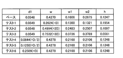
- FIG. 8 is a chart according to the present embodiment.
- 9 and 10 are graphs according to this example.
- the concave portion has an arc portion, an open portion, and an inclined surface, as shown in FIGS. 2 and 3, and is disposed on both sides in the axial direction of the processing hole. Then, in Tests 1 to 3, the axial dimension w of the recess was changed. Further, in the tests 4 to 6, the shortest distance d1 to the opening edge of the processed hole of the recess was changed.
- the unit of numerical values in FIG. 8 is inches.
- each ⁇ is a rear rear nodal point (the upper end 1a in the axial direction of the opening of the machined hole 1 in FIG. 2), and Kt at these nodal points is shown.
- Kt is a stress concentration coefficient, which is a ratio of an analysis result to a theoretical stress at infinity.
Landscapes
- Engineering & Computer Science (AREA)
- Mechanical Engineering (AREA)
- General Engineering & Computer Science (AREA)
- Chemical & Material Sciences (AREA)
- Combustion & Propulsion (AREA)
- Structures Of Non-Positive Displacement Pumps (AREA)
Abstract
加工を容易に行うことができ円筒部材に形成された加工穴に対する応力集中を低減する。円筒部材(10)に形成された加工穴1の周方向の側部において加工穴(1)の深さ方向に凹む凹部(2)が形成されており、凹部(2)は、開口縁の一部が円弧形状の円弧部(2a)に形成され、底部が円弧部(2a)に沿う部分から円弧形状が開放される開放部(2b)に向けて傾斜面(2c)により漸次浅く形成され、円弧部(2a)が加工穴(1)に向けて配置される。
Description
本発明は、応力低減構造、応力低減構造を備えるガスタービンケーシングおよびガスタービンに関する。
例えば、特許文献1には、ピストンのピンボスにおける円孔の口元に発生する応力集中をなくすため、円孔が設けられた入口面において圧縮荷重が集中する点Aの近くに円孔の深さ方向にくぼみを設け、圧縮荷重を点Aの側部に分散させることが示されている。
また、例えば、特許文献2には、ガスタービンエンジンのケースに設けられた穴に生じるフープ応力を低減するため、穴のフープ方向の両側にパケット(凹部)を設けることが示されている。ポケットは、レーストラック形状を含む円形の外縁を有し、平坦な底部、湾曲した底部、または球形の形状を含むことが示されている。
ところで、ガスタービンなどの回転構造物のケーシングは円筒形状に形成されており、起動時や停止時に生じる温度差により高い熱応力が発生する。また、運転に伴いケーシング内部の圧力は上昇し、円筒形状に対して周方向の引っ張り応力であるフープ応力が発生する。このようなケーシングには、外部部品などを取り付けるための加工穴が形成されている。そして、加工穴は、上述した高い熱応力やフープ応力が起動や停止で繰り返し掛かることから、低サイクル疲労寿命が大幅に低下することとなる。加工穴周りのフープ応力の低減策としては、加工穴近傍の肉厚化が一般的であるが、航空用のガスタービンとしては重量増加を極力抑える観点から好ましくない。
特許文献2には、上述したようにガスタービンエンジンのケースに設けられた穴に生じるフープ応力を低減する工夫が施されることは示されているが、当該特許文献2に示されるような平坦な底部、湾曲した底部、または球形の形状のポケットは、加工性が悪く高コストとなる問題がある。
本発明は上述した課題を解決するものであり、加工を容易に行うことができ円筒部材に形成された加工穴に対する応力集中を低減することのできる応力低減構造、ガスタービンケーシングおよびガスタービンを提供することを目的とする。
上述の目的を達成するために、本発明の一態様に係る応力低減構造は、円筒部材に形成された加工穴の周方向の側部において前記加工穴の深さ方向に凹む凹部が形成されており、前記凹部は、開口縁の一部が円弧形状に形成され、底部が前記円弧形状に沿う部分から前記円弧形状の開放側に向けて傾斜面により漸次浅く形成され、前記円弧形状の部分が前記加工穴に向けて配置されている。
この応力低減構造によれば、円筒部材に形成された加工穴の周方向の側部において加工穴の深さ方向に凹む凹部が形成されている。このため、加工穴の周方向に生じる引っ張り荷重が凹部により緩和されて、引っ張り荷重の掛かる位置が加工穴の開口部から深さ方向に変位し、開口部において荷重が抑制されることで、加工穴の開口部の軸方向の両端での応力集中を低減することができる。そして、このように作用する凹部は、開口縁の一部が円弧形状に形成され、底部が円弧形状に沿う部分から円弧形状の開放側に向けて傾斜面により漸次浅く形成されていることから、例えばエンドミルのような工具で円筒部材の表面に対して先端の一部が接触するように回転軸を斜めにして加工を行うことで多くの加工手数を伴わず容易に形成することができる。そして、このような形状に形成された凹部は、底部が比較的深い円弧形状の部分が加工穴に向けて配置されているため、加工穴の周方向に生じる引っ張り荷重を緩和する効果を顕著に得ることができる。この結果、重量増加を抑えつつ、円筒部材に形成された加工穴に対する応力集中を低減することができる。
また、本発明の一態様に係る応力低減構造では、前記凹部は、最も深い深さhが前記加工穴が形成された前記円筒部材の板厚Hの50%以下の範囲であることが好ましい。
この応力低減構造によれば、凹部の最も深い深さhが加工穴が形成された円筒部材の板厚Hの50%以下であれば、引っ張り荷重の掛かる位置を加工穴の開口部から深さ方向に変位させて開口部における荷重を抑制する効果を顕著に得ることができ、かつ凹部自体に引っ張り荷重が掛かる事態を抑制することができる。
また、本発明の一態様に係る応力低減構造では、前記凹部は、前記加工穴の開口縁との最短距離d1が前記加工穴の周方向の差し渡し寸法Dの50%以下の範囲であることが好ましい。
この応力低減構造によれば、凹部の最短距離d1が加工穴の周方向の差し渡し寸法Dの50%以下であれば、加工穴の開口部における荷重を抑制する効果を顕著に得ることができる。
また、本発明の一態様に係る応力低減構造では、前記凹部は、周方向の差し渡し寸法d2が前記加工穴の周方向の差し渡し寸法Dの100%以上300%以下の範囲であることが好ましい。
この応力低減構造によれば、凹部の周方向の差し渡し寸法d2が加工穴の周方向の差し渡し寸法Dの100%以上であれば、加工穴の開口部における荷重を抑制する効果を顕著に得ることができる。一方、凹部の周方向の差し渡し寸法d2が加工穴の周方向の差し渡し寸法Dの300%以下であれば、加工穴の開口部における荷重を抑制する効果を顕著に得つつ、凹部を設けることによる円筒部材の強度低下を抑えることができる。
また、本発明の一態様に係る応力低減構造では、前記凹部は、軸方向の差し渡し寸法wが前記加工穴の軸方向の差し渡し寸法Wの100%以上300%以下の範囲であり、前記寸法wの範囲の周方向の位置に前記加工穴の前記寸法Wが含まれることが好ましい。
この応力低減構造によれば、凹部の軸方向の差し渡し寸法wが加工穴の軸方向の差し渡し寸法Wの100%以上で寸法wの範囲の周方向の位置に加工穴の寸法Wが含まれていれば、加工穴の開口部における荷重を抑制する効果を顕著に得ることができる。一方、凹部の軸方向の差し渡し寸法wが加工穴の軸方向の差し渡し寸法Wの300%以下で寸法wの範囲の周方向の位置に加工穴の寸法Wが含まれていれば、加工穴の開口部における荷重を抑制する効果を顕著に得つつ、凹部を設けることによる円筒部材の強度低下を抑えることができる。
また、本発明の一態様に係る応力低減構造では、前記凹部は、前記加工穴の周方向の両側部に配置されていることが好ましい。
この応力低減構造によれば、凹部が加工穴の周方向の両側部に配置されていることで、加工穴の周方向両側に生じる引っ張り荷重を緩和する作用を顕著に得ることができる。
また、本発明の一態様に係る応力低減構造では、前記凹部は、前記加工穴の周方向の両側部に配置されて、前記加工穴の中心を基準とする対称形状に形成されていることが好ましい。
この応力低減構造によれば、凹部が加工穴の周方向の両側部に配置され、かつ加工穴の中心を基準とする対称形状に形成されていることで、加工穴の周方向両側に生じる引っ張り荷重を緩和する作用を顕著に得ることができ、かつ周方向両側で均等に得ることができる。
また、本発明の一態様に係る応力低減構造では、前記加工穴は、周方向が長尺の楕円形状に形成されていることが好ましい。
この応力低減構造によれば、加工穴が周方向が長尺の楕円形状に形成されていることで、応力の集中する軸方向の両端における曲率が円形状に比較して大きくなるため、応力が両端の周方向に分散しやすくなる。この結果、凹部による効果と相乗して加工穴の開口部の軸方向の両端での応力集中を低減することができる。
上述の目的を達成するために、本発明の一態様に係るガスタービンケーシングは、上述した加工穴および凹部を有する円筒部材をなす。
このガスタービンケーシングによれば、高い熱応力やフープ応力が発生した場合の加工穴を基にした低サイクル疲労寿命の低下を抑制することができる。
上述の目的を達成するために、本発明の一態様に係るガスタービンは、上述したガスタービンケーシングを外郭として備える。
このガスタービンによれば、ガスタービンケーシングにおいて低サイクル疲労寿命の低下が抑制されるため、長寿命化を図り信頼性を向上することができる。
本発明によれば、加工を容易に行うことができ円筒部材に形成された加工穴に対する応力集中を低減することができる。
以下に、本発明に係る実施形態を図面に基づいて詳細に説明する。なお、この実施形態によりこの発明が限定されるものではない。また、下記実施形態における構成要素には、当業者が置換可能かつ容易なもの、あるいは実質的に同一のものが含まれる。
図1は、本実施形態に係るガスタービンの概略構成図である。
図1に示すガスタービンは、航空用ガスタービンである。この航空用ガスタービンは、ファンケーシング11とガスタービンケーシング12とを有している。ファンケーシング11は、その内部にファン13が収容されている。ガスタービンケーシング12は、圧縮機ケーシング12Aと燃焼器ケーシング12Bとタービンケーシング12Cとが連続して配置されて円筒形状に形成されたもので、圧縮機ケーシング12A内に圧縮機14、燃焼器ケーシング12B内に燃焼器15、タービンケーシング12C内にタービン16がそれぞれ収容されている。
ファン13は、回転軸21の外周部に複数のファンブレード22が装着されて構成されている。圧縮機14は、低圧コンプレッサ23と高圧コンプレッサ24とを有している。燃焼器15は、圧縮機14より下流側に位置し、周方向に複数配置されている。タービン16は、燃焼器15より下流側に位置し、高圧タービン25および低圧タービン26を有している。そして、ファン13の回転軸21と低圧コンプレッサ23とが連結され、低圧コンプレッサ23と低圧タービン26とが第一ロータ軸27により連結されている。また、高圧コンプレッサ24と高圧タービン25とが、第一ロータ軸27の外周側に位置する円筒形状をなす第二ロータ軸28により連結されている。
従って、圧縮機14にて、空気取入口から取り込まれた空気が、低圧コンプレッサ23と高圧コンプレッサ24における図示しない複数の静翼と動翼を通過して圧縮されることで高温・高圧の圧縮空気となる。燃焼器15にて、この圧縮空気に対して所定の燃料が供給され、燃焼する。この燃焼器15で生成された作動流体である高温・高圧の燃焼ガスが、タービン16を構成する高圧タービン25および低圧タービン26における図示しない複数の静翼と動翼を通過することで第一ロータ軸27および第二ロータ軸28が駆動回転する。この場合、低圧タービン26の回転力が第一ロータ軸27により低圧コンプレッサ23に伝達されて駆動する。また、高圧タービン25の回転力が第二ロータ軸28により高圧コンプレッサ24に伝達されて駆動する。その結果、ファン13を駆動することができると共に、タービン16から排出される排気ガスにより推力を得ることができる。
なお、本実施形態に係るガスタービンは、上述した航空用ガスタービンに限定されるものではなく、例えば、発電用ガスタービンなどを含む。
本実施形態に係る応力低減構造は、上述したようなガスタービンにおけるガスタービンケーシング12に適用される。上述したようにガスタービンケーシング12は円筒形状に形成されたもので、ガスタービンの起動時や停止時に生じる温度差により高い熱応力が発生する。また、運転に伴いガスタービンケーシング12の内部の圧力は上昇し、円筒形状に対して周方向の引っ張り応力であるフープ応力が発生する。このような高い熱応力やフープ応力は、特に、燃焼ガスを生成する燃焼器ケーシング12Bにおいて発生する。ここで、周方向とは、図1において第一ロータ軸27および第二ロータ軸28の回転中心となる軸心Rを中心とした周り方向をいう。また、以下の説明において軸方向とは、軸心Rに平行な方向をいう。
図2は、本実施形態に係る応力低減構造の平面図である。図3は、図2におけるA-A断面図である。図4は、本実施形態に係る応力低減構造の製造方法を示す平面図である。図5は、図4におけるB-B断面図である。図6は、図2におけるC-C断面図である。
図2から図6は、円筒形状の円筒部材10の一部として、上述したガスタービンケーシング12(特に、燃焼器ケーシング12B)の一部を示している。円筒部材10は、外部部品などを取り付けるための加工穴1が形成されている。
加工穴1は、上述した高い熱応力やフープ応力が起動や停止で繰り返し掛かることから、図2において周方向の引っ張り荷重により開口部の軸方向の両端1aに応力が集中し、これにより円筒部材10の低サイクル疲労寿命が大幅に低下することとなる。従って、本実施形態の応力低減構造は、円筒部材10に形成された加工穴1に対して周方向の引っ張り荷重を抑制し応力集中を低減するためにある。
本実施形態の応力低減構造は、加工穴1の周方向の側部において加工穴1の深さ方向に凹む凹部2が形成されている。この凹部2は、図2に示すように、開口縁が、その一部を円弧形状(馬蹄形状またはC字形状)に形成された円弧部2aと、円弧形状が開放されて円弧形状の両端が直線状に繋がれた開放部2bとで形成されている。また、凹部2は、図3に示すように、底部が、円弧部2aに沿う部分から開放部2b側に向けて傾斜面2cにより漸次浅く形成されている。すなわち、凹部2の底部は、円弧部2aに沿う部分が深く、特に円弧部2aの中央部が最も深く形成され、開放部2bに近づくにつれて傾斜面2cにより浅くなるように形成されている。この凹部2は、円弧形状の円弧部2aを加工穴1に向けて配置されている。
この凹部2は、図4および図5に示すように、切削に用いられる円柱形状のエンドミル100を用い、円筒部材10の表面に対して先端の一部が接触するように回転軸Ceを斜めにして加工を行うことで形成する。従って、凹部2は、エンドミル100の先端の一部が円筒部材10の表面に対して斜めに接触することで、上述した円弧部2a、開放部2b、および傾斜面2cが形成される。また、凹部2は、図3および図5に示すように、円弧部2aに沿う内面が湾曲して滑らかに形成されており、この内面はエンドミル100の切削刃(図示せず)の形状により滑らかに形成される。このように、凹部2は、多くの工具を用いたり工具を移動させたりして加工手数を伴わず、1つのエンドミル100により容易に形成することができる。
この本実施形態の応力低減構造によれば、円筒部材10に形成された加工穴1の周方向の側部において加工穴1の深さ方向に凹む凹部2が形成されている。このため、加工穴1の周方向に生じる引っ張り荷重が凹部2により緩和されて、引っ張り荷重の掛かる位置が加工穴1の開口部から深さ方向に変位し、開口部において荷重が抑制されることで、加工穴1の開口部の軸方向の両端1aでの応力集中を低減することができる。そして、このように作用する凹部2は、開口縁の一部が円弧形状に形成された円弧部2aを有し、底部が円弧部2aに沿う部分から円弧形状が開放される開放部2bに向けて傾斜面2cにより漸次浅く形成され、上述したようにエンドミル100で円筒部材10の表面に対して先端の一部が接触するように回転軸Ceを斜めにして加工を行うことで多くの加工手数を伴わず容易に形成することができる。そして、このような形状に形成された凹部2は、底部が比較的深い円弧部2aが加工穴1に向けて配置されているため、加工穴1の周方向に生じる引っ張り荷重を緩和する効果を顕著に得ることができる。この結果、重量増加を抑えつつ、円筒部材10に形成された加工穴1に対する応力集中を低減することができる。
なお、凹部2は、底部が比較的深い円弧部2aが加工穴1に向けて配置されていれば、加工穴1の周方向に生じる引っ張り荷重を緩和する効果を顕著に得ることができるため、図2に示すように開放部2bが軸方向に向けて配置されていなくてもよく、例えば、開放部2bが周方向で加工穴1の反対方向に向けて配置されている構成であってもよい。
また、凹部2は、円弧部2aに沿う内面が湾曲して滑らかに形成されて傾斜面2cに連続していることで、内面に角部を有する形状と比較して凹部2自体に引っ張り荷重が掛かる事態を抑制することができる。
なお、凹部2は、加工穴1が貫通している場合、円筒部材10の筒内側または筒外側で開口する加工穴1の周方向の側部に設けられる。また、加工穴1が貫通していない場合、凹部2は、加工穴1が開口する側で加工穴1の周方向の側部に設けられる。
また、本実施形態の応力低減構造では、図5および図6に示すように、凹部2は、最も深い深さhが加工穴1が形成された円筒部材10の板厚Hの50%以下の範囲であることが好ましい。
凹部2の最も深い深さhが加工穴1が形成された円筒部材10の板厚Hの50%以下であれば、引っ張り荷重の掛かる位置を加工穴1の開口部から深さ方向に変位させて開口部における荷重を抑制する効果を顕著に得ることができ、かつ凹部2自体に引っ張り荷重が掛かる事態を抑制することができる。
また、本実施形態の応力低減構造では、図2および図6に示すように、凹部2は、加工穴1の開口縁との最短距離d1が加工穴1の周方向の差し渡し寸法Dの50%以下の範囲であることが好ましい。
凹部2の最短距離d1が加工穴1の周方向の差し渡し寸法Dの50%以下であれば、加工穴1の開口部における荷重を抑制する効果を顕著に得ることができる。
また、本実施形態の応力低減構造では、図2に示すように、凹部2は、周方向の差し渡し寸法d2が加工穴1の周方向の差し渡し寸法Dの100%以上300%以下の範囲であることが好ましい。
凹部2の周方向の差し渡し寸法d2が加工穴1の周方向の差し渡し寸法Dの100%以上であれば、加工穴1の開口部における荷重を抑制する効果を顕著に得ることができる。一方、凹部2の周方向の差し渡し寸法d2が加工穴1の周方向の差し渡し寸法Dの300%以下であれば、加工穴1の開口部における荷重を抑制する効果を顕著に得つつ、凹部2を設けることによる円筒部材10の強度低下を抑えることができる。
また、本実施形態の応力低減構造では、図2に示すように、凹部2は、軸方向の差し渡し寸法wが加工穴1の軸方向の差し渡し寸法Wの100%以上300%以下の範囲であり、寸法wの範囲の周方向の位置に加工穴1の寸法Wが含まれることが好ましい。
凹部2の軸方向の差し渡し寸法wが加工穴1の軸方向の差し渡し寸法Wの100%以上で寸法wの範囲の周方向の位置に加工穴1の寸法Wが含まれていれば、加工穴1の開口部における荷重を抑制する効果を顕著に得ることができる。一方、凹部2の軸方向の差し渡し寸法wが加工穴1の軸方向の差し渡し寸法Wの300%以下で寸法wの範囲の周方向の位置に加工穴1の寸法Wが含まれていれば、加工穴1の開口部における荷重を抑制する効果を顕著に得つつ、凹部2を設けることによる円筒部材10の強度低下を抑えることができる。
また、本実施形態の応力低減構造では、図2に示すように、凹部2は、加工穴1の周方向の両側部に配置されていることが好ましい。
凹部2は、加工穴1の周方向の一方の側部に配置されていても上記の効果を得ることができるが、凹部2が加工穴1の周方向の両側部に配置されていることで、加工穴1の周方向両側に生じる引っ張り荷重を緩和する作用を顕著に得ることができる。
また、本実施形態の応力低減構造では、図2に示すように、凹部2は、加工穴1の周方向の両側部に配置されて、加工穴1の中心を基準とする対称形状に形成されていることが好ましい。
凹部2は、加工穴1の周方向の一方の側部に配置されて加工穴1の中心を基準として非対称に形成されていても上記の効果を得ることができるが、凹部2が加工穴1の周方向の両側部に配置され、かつ加工穴1の中心を基準とする対称形状に形成されていることで、加工穴1の周方向両側に生じる引っ張り荷重を緩和する作用を顕著に得ることができ、かつ周方向両側で均等に得ることができる。
図7は、本発明の実施形態に係る応力低減構造の他の例を示す平面図である。
本実施形態の応力低減構造では、図7に示すように、加工穴1は、周方向が長尺の楕円形状に形成されていることが好ましい。
加工穴1が図2に示すような真円形状に形成されていても上述の効果を得ることができるが、加工穴1が周方向が長尺の楕円形状に形成されていることで、応力の集中する軸方向の両端1aにおける曲率が円形状に比較して大きくなるため、応力が両端1aの周方向に分散しやすくなる。この結果、凹部2による効果と相乗して加工穴1の開口部の軸方向の両端1aでの応力集中を低減することができる。
また、本実施形態のガスタービンケーシング12は、上述した加工穴1および凹部2を有する円筒部材10をなすことが好ましい。
このガスタービンケーシング12によれば、高い熱応力やフープ応力が発生した場合の加工穴1を基にした低サイクル疲労寿命の低下を抑制することができる。
また、本実施形態のガスタービンは、上記ガスタービンケーシング12を外郭に備えることが好ましい。
このガスタービンによれば、ガスタービンケーシング12において低サイクル疲労寿命の低下が抑制されるため、長寿命化を図り信頼性を向上することができる。
以下、実施例について説明する。図8は、本実施例に係る図表である。図9および図10は、本実施例に係るグラフである。
本実施例では、ベース、テスト1~6について3次元での静的構造解析を行った。ベース、テスト1~6は、図8に示すように、凹部の加工穴の開口縁との最短距離d1、凹部の軸方向の差し渡し寸法w、加工穴の中心から軸方向への凹部の円弧部側の寸法w1(図2参照)、加工穴の中心から軸方向への凹部の開放部側の寸法w2(図2参照)、凹部の最も深い深さhについて規定している。加工穴は、図2を参照するように、真円形状であり差し渡し寸法Dはベース、テスト1~6において同一(0.26)である。凹部は、図2および図3を参照するように、円弧部、開放部、および傾斜面を有し、加工穴の軸方向の両側部に配置されている。そして、テスト1~3は、凹部の軸方向の差し渡し寸法wを変化させた。また、テスト4~6は、凹部の加工穴の開口縁との最短距離d1を変化させた。なお、図8における数値の単位はインチである。
図9および図10において、各◇は加工穴の外側後方の節点(図2における加工穴1の開口部の軸方向の上側の端1a)であり、これら節点におけるKtを示している。Ktは、(応力集中係数であって解析結果と無限遠での理論応力の比である。
テスト1~3において、図9に示すように、Ktは、w=Dに対してw=2Dの場合に2割近く減少し、w=3Dの場合に5割近く減少することが分かる。なお、図9には明示しないが、図2における加工穴1の開口部の軸方向の下側の端1aでも同様の傾向となる。従って、w=Dに対してDを大きくすると応力低減効果が得られることが分かる。
テスト4~6において、図10に示すように、Ktは、d1=Dに対してd1=D/2、d1=D/3の場合に1割近く減少することが分かる。なお、図10には明示しないが、図2における加工穴1の開口部の軸方向の下側の端1aでも同様の傾向となる。従って、d1=Dに対してDを大きくすると応力低減効果が得られることが分かる。
1 加工穴
1a 軸方向の端
2 凹部
2a 円弧部
2b 開放部
2c 傾斜面
10 円筒部材
12 ガスタービンケーシング
1a 軸方向の端
2 凹部
2a 円弧部
2b 開放部
2c 傾斜面
10 円筒部材
12 ガスタービンケーシング
Claims (10)
- 円筒部材に形成された加工穴の周方向の側部において前記加工穴の深さ方向に凹む凹部が形成されており、前記凹部は、開口縁の一部が円弧形状に形成され、底部が前記円弧形状に沿う部分から前記円弧形状の開放側に向けて傾斜面により漸次浅く形成され、前記円弧形状の部分が前記加工穴に向けて配置されている、応力低減構造。
- 前記凹部は、最も深い深さhが前記加工穴が形成された前記円筒部材の板厚Hの50%以下の範囲である、請求項1に記載の応力低減構造。
- 前記凹部は、前記加工穴の開口縁との最短距離d1が前記加工穴の周方向の差し渡し寸法Dの50%以下の範囲である、請求項1または2に記載の応力低減構造。
- 前記凹部は、周方向の差し渡し寸法d2が前記加工穴の周方向の差し渡し寸法Dの100%以上300%以下の範囲である、請求項1から3のいずれか1つに記載の応力低減構造。
- 前記凹部は、軸方向の差し渡し寸法wが前記加工穴の軸方向の差し渡し寸法Wの100%以上300%以下の範囲であり、前記寸法wの範囲の周方向の位置に前記加工穴の前記寸法Wが含まれる、請求項1から4のいずれか1つに記載の応力低減構造。
- 前記凹部は、前記加工穴の周方向の両側部に配置されている、請求項1から5のいずれか1つに記載の応力低減構造。
- 前記凹部は、前記加工穴の周方向の両側部に配置されて、前記加工穴の中心を基準とする対称形状に形成されている、請求項1から5のいずれか1つに記載の応力低減構造。
- 前記加工穴は、周方向が長尺の楕円形状に形成されている、請求項1から7のいずれか1つに記載の応力低減構造。
- 請求項1から8のいずれか1つに記載の加工穴および凹部を有する円筒部材をなす、ガスタービンケーシング。
- 請求項9に記載のガスタービンケーシングを外郭に備える、ガスタービン。
Priority Applications (3)
| Application Number | Priority Date | Filing Date | Title |
|---|---|---|---|
| EP18819966.5A EP3643903B1 (en) | 2017-06-21 | 2018-04-09 | Stress reduction structure in a gas turbine casing, and gas turbine engine |
| CA3066209A CA3066209C (en) | 2017-06-21 | 2018-04-09 | Stress reduction structure, gas turbine casing, and gas turbine |
| US16/623,434 US11168586B2 (en) | 2017-06-21 | 2018-04-09 | Stress reduction structure, gas turbine casing, and gas turbine |
Applications Claiming Priority (2)
| Application Number | Priority Date | Filing Date | Title |
|---|---|---|---|
| JP2017-121293 | 2017-06-21 | ||
| JP2017121293A JP6800813B2 (ja) | 2017-06-21 | 2017-06-21 | 応力低減構造、ガスタービンケーシングおよびガスタービン |
Publications (1)
| Publication Number | Publication Date |
|---|---|
| WO2018235394A1 true WO2018235394A1 (ja) | 2018-12-27 |
Family
ID=64735670
Family Applications (1)
| Application Number | Title | Priority Date | Filing Date |
|---|---|---|---|
| PCT/JP2018/014929 Ceased WO2018235394A1 (ja) | 2017-06-21 | 2018-04-09 | 応力低減構造、ガスタービンケーシングおよびガスタービン |
Country Status (5)
| Country | Link |
|---|---|
| US (1) | US11168586B2 (ja) |
| EP (1) | EP3643903B1 (ja) |
| JP (1) | JP6800813B2 (ja) |
| CA (1) | CA3066209C (ja) |
| WO (1) | WO2018235394A1 (ja) |
Citations (6)
| Publication number | Priority date | Publication date | Assignee | Title |
|---|---|---|---|---|
| JPH0345449U (ja) * | 1989-09-11 | 1991-04-26 | ||
| JPH05240110A (ja) | 1992-02-28 | 1993-09-17 | Suzuki Motor Corp | 内燃機関のピストン |
| US20020015642A1 (en) * | 2000-07-07 | 2002-02-07 | London Richard Allan | Turbine disc |
| US20110064580A1 (en) * | 2009-09-16 | 2011-03-17 | United Technologies Corporation | Turbofan flow path trenches |
| WO2013141401A1 (ja) * | 2012-03-23 | 2013-09-26 | 日本発條株式会社 | 皿ばね |
| WO2015038931A1 (en) | 2013-09-13 | 2015-03-19 | United Technologies Corporation | Shielding pockets for case holes |
Family Cites Families (10)
| Publication number | Priority date | Publication date | Assignee | Title |
|---|---|---|---|---|
| US3661045A (en) | 1970-09-17 | 1972-05-09 | Tyco Lab | Apparatus for stabilizing a rotary saw blade |
| US5485723A (en) * | 1994-04-29 | 1996-01-23 | United Technologies Corporation | Variable thickness isogrid case |
| GB2296039A (en) | 1994-12-16 | 1996-06-19 | Perkins Ltd | Stress reduction at a high pressure fluid passage junction |
| US6237344B1 (en) * | 1998-07-20 | 2001-05-29 | General Electric Company | Dimpled impingement baffle |
| JP2003075489A (ja) * | 2001-09-07 | 2003-03-12 | Communication Research Laboratory | 無線機器の空中線電力測定方法及びそれに用いる電波暗箱 |
| US6681577B2 (en) * | 2002-01-16 | 2004-01-27 | General Electric Company | Method and apparatus for relieving stress in a combustion case in a gas turbine engine |
| JP5137365B2 (ja) | 2006-09-20 | 2013-02-06 | エドワーズ株式会社 | 真空ポンプ及びフランジ |
| US9157328B2 (en) | 2010-12-24 | 2015-10-13 | Rolls-Royce North American Technologies, Inc. | Cooled gas turbine engine component |
| EP3967854B1 (en) * | 2013-11-25 | 2023-07-05 | Raytheon Technologies Corporation | Assembly for a turbine engine |
| WO2015130381A2 (en) | 2013-12-20 | 2015-09-03 | United Technologies Corporation | A gas turbine engine integrally bladed rotor with asymmetrical trench fillets |
-
2017
- 2017-06-21 JP JP2017121293A patent/JP6800813B2/ja active Active
-
2018
- 2018-04-09 US US16/623,434 patent/US11168586B2/en active Active
- 2018-04-09 EP EP18819966.5A patent/EP3643903B1/en active Active
- 2018-04-09 WO PCT/JP2018/014929 patent/WO2018235394A1/ja not_active Ceased
- 2018-04-09 CA CA3066209A patent/CA3066209C/en active Active
Patent Citations (7)
| Publication number | Priority date | Publication date | Assignee | Title |
|---|---|---|---|---|
| JPH0345449U (ja) * | 1989-09-11 | 1991-04-26 | ||
| JPH05240110A (ja) | 1992-02-28 | 1993-09-17 | Suzuki Motor Corp | 内燃機関のピストン |
| US20020015642A1 (en) * | 2000-07-07 | 2002-02-07 | London Richard Allan | Turbine disc |
| US20110064580A1 (en) * | 2009-09-16 | 2011-03-17 | United Technologies Corporation | Turbofan flow path trenches |
| WO2013141401A1 (ja) * | 2012-03-23 | 2013-09-26 | 日本発條株式会社 | 皿ばね |
| WO2015038931A1 (en) | 2013-09-13 | 2015-03-19 | United Technologies Corporation | Shielding pockets for case holes |
| US20160201511A1 (en) * | 2013-09-13 | 2016-07-14 | United Technologies Corporation | Shielding pockets for case holes |
Non-Patent Citations (1)
| Title |
|---|
| See also references of EP3643903A4 |
Also Published As
| Publication number | Publication date |
|---|---|
| EP3643903B1 (en) | 2022-02-23 |
| JP2019007368A (ja) | 2019-01-17 |
| CA3066209A1 (en) | 2018-12-27 |
| US11168586B2 (en) | 2021-11-09 |
| CA3066209C (en) | 2023-03-07 |
| JP6800813B2 (ja) | 2020-12-16 |
| EP3643903A1 (en) | 2020-04-29 |
| US20200109647A1 (en) | 2020-04-09 |
| EP3643903A4 (en) | 2020-12-23 |
Similar Documents
| Publication | Publication Date | Title |
|---|---|---|
| KR101070904B1 (ko) | 레이디얼 터빈 휠 | |
| US20160032739A1 (en) | Axial flow compressor and gas turbine equipped with axial flow compressor | |
| JP6945284B2 (ja) | タービンブレード用ダンパピン | |
| CN105041870A (zh) | 用于空气轴承的轴承套筒 | |
| CN104136719A (zh) | 涡轮发动机转子叶片凹槽 | |
| JP2016035209A5 (ja) | ||
| JP2017048788A (ja) | タービンブレード用ダンパピン | |
| JP2017048791A (ja) | 隣接するタービンブレードの制振用ダンパピン | |
| JP2017082758A (ja) | タービンブレード用スロット付きダンパピン | |
| US20170254210A1 (en) | Airfoil tip geometry to reduce blade wear in gas turbine engines | |
| JP7196120B2 (ja) | タービンホイール | |
| TW201819751A (zh) | 流體壓縮裝置的雙面壓縮葉輪及其製造方法 | |
| JP6929031B2 (ja) | タービンブレード用ダンパピン | |
| JP6986155B2 (ja) | タービン動翼、ターボ機械及びコンタクト面製造方法 | |
| WO2018235394A1 (ja) | 応力低減構造、ガスタービンケーシングおよびガスタービン | |
| JP5223779B2 (ja) | コンプレッサ及びこれを用いたターボチャージャ | |
| JP2008133763A (ja) | スクリュー流体機械 | |
| JP5987374B2 (ja) | ターボ機械及び過給機 | |
| CN103452905A (zh) | 压缩机 | |
| JP7235536B2 (ja) | 回転機械 | |
| JP5039676B2 (ja) | 回転体ボルト締結構造及び回転機械 | |
| US12163443B2 (en) | Turbine rotor blade and turbine | |
| KR102610387B1 (ko) | 로터 및 압축기 | |
| JP5894224B2 (ja) | ロータリータービンエンジン | |
| RU128247U1 (ru) | Вал турбомашины |
Legal Events
| Date | Code | Title | Description |
|---|---|---|---|
| 121 | Ep: the epo has been informed by wipo that ep was designated in this application |
Ref document number: 18819966 Country of ref document: EP Kind code of ref document: A1 |
|
| ENP | Entry into the national phase |
Ref document number: 3066209 Country of ref document: CA |
|
| NENP | Non-entry into the national phase |
Ref country code: DE |
|
| ENP | Entry into the national phase |
Ref document number: 2018819966 Country of ref document: EP Effective date: 20200121 |