WO2013141401A1 - 皿ばね - Google Patents
皿ばね Download PDFInfo
- Publication number
- WO2013141401A1 WO2013141401A1 PCT/JP2013/058570 JP2013058570W WO2013141401A1 WO 2013141401 A1 WO2013141401 A1 WO 2013141401A1 JP 2013058570 W JP2013058570 W JP 2013058570W WO 2013141401 A1 WO2013141401 A1 WO 2013141401A1
- Authority
- WO
- WIPO (PCT)
- Prior art keywords
- disc spring
- long
- elliptical
- short
- radius
- Prior art date
- Legal status (The legal status is an assumption and is not a legal conclusion. Google has not performed a legal analysis and makes no representation as to the accuracy of the status listed.)
- Ceased
Links
Images




Classifications
-
- F—MECHANICAL ENGINEERING; LIGHTING; HEATING; WEAPONS; BLASTING
- F16—ENGINEERING ELEMENTS AND UNITS; GENERAL MEASURES FOR PRODUCING AND MAINTAINING EFFECTIVE FUNCTIONING OF MACHINES OR INSTALLATIONS; THERMAL INSULATION IN GENERAL
- F16F—SPRINGS; SHOCK-ABSORBERS; MEANS FOR DAMPING VIBRATION
- F16F1/00—Springs
- F16F1/02—Springs made of steel or other material having low internal friction; Wound, torsion, leaf, cup, ring or the like springs, the material of the spring not being relevant
- F16F1/32—Belleville-type springs
-
- F—MECHANICAL ENGINEERING; LIGHTING; HEATING; WEAPONS; BLASTING
- F16—ENGINEERING ELEMENTS AND UNITS; GENERAL MEASURES FOR PRODUCING AND MAINTAINING EFFECTIVE FUNCTIONING OF MACHINES OR INSTALLATIONS; THERMAL INSULATION IN GENERAL
- F16F—SPRINGS; SHOCK-ABSORBERS; MEANS FOR DAMPING VIBRATION
- F16F1/00—Springs
- F16F1/02—Springs made of steel or other material having low internal friction; Wound, torsion, leaf, cup, ring or the like springs, the material of the spring not being relevant
- F16F1/025—Springs made of steel or other material having low internal friction; Wound, torsion, leaf, cup, ring or the like springs, the material of the spring not being relevant characterised by having a particular shape
-
- F—MECHANICAL ENGINEERING; LIGHTING; HEATING; WEAPONS; BLASTING
- F16—ENGINEERING ELEMENTS AND UNITS; GENERAL MEASURES FOR PRODUCING AND MAINTAINING EFFECTIVE FUNCTIONING OF MACHINES OR INSTALLATIONS; THERMAL INSULATION IN GENERAL
- F16F—SPRINGS; SHOCK-ABSORBERS; MEANS FOR DAMPING VIBRATION
- F16F1/00—Springs
- F16F1/02—Springs made of steel or other material having low internal friction; Wound, torsion, leaf, cup, ring or the like springs, the material of the spring not being relevant
- F16F1/025—Springs made of steel or other material having low internal friction; Wound, torsion, leaf, cup, ring or the like springs, the material of the spring not being relevant characterised by having a particular shape
- F16F1/027—Planar, e.g. in sheet form; leaf springs
-
- F—MECHANICAL ENGINEERING; LIGHTING; HEATING; WEAPONS; BLASTING
- F16—ENGINEERING ELEMENTS AND UNITS; GENERAL MEASURES FOR PRODUCING AND MAINTAINING EFFECTIVE FUNCTIONING OF MACHINES OR INSTALLATIONS; THERMAL INSULATION IN GENERAL
- F16F—SPRINGS; SHOCK-ABSORBERS; MEANS FOR DAMPING VIBRATION
- F16F1/00—Springs
- F16F1/02—Springs made of steel or other material having low internal friction; Wound, torsion, leaf, cup, ring or the like springs, the material of the spring not being relevant
- F16F1/04—Wound springs
- F16F1/08—Wound springs with turns lying in mainly conical surfaces, i.e. characterised by varying diameter
-
- F—MECHANICAL ENGINEERING; LIGHTING; HEATING; WEAPONS; BLASTING
- F16—ENGINEERING ELEMENTS AND UNITS; GENERAL MEASURES FOR PRODUCING AND MAINTAINING EFFECTIVE FUNCTIONING OF MACHINES OR INSTALLATIONS; THERMAL INSULATION IN GENERAL
- F16F—SPRINGS; SHOCK-ABSORBERS; MEANS FOR DAMPING VIBRATION
- F16F1/00—Springs
- F16F1/02—Springs made of steel or other material having low internal friction; Wound, torsion, leaf, cup, ring or the like springs, the material of the spring not being relevant
- F16F1/34—Ring springs, i.e. annular bodies deformed radially due to axial load
Definitions
- the present invention relates to a disc spring used for various applications such as a pressing means and an impact buffering means, and more particularly to an improvement in the shape of the body of the disc spring.
- the disc spring includes a disc-shaped (substantially conical) main body, and the main body has a ring shape with a hole in the center.
- Disc springs are used in various applications such as pressing means and impact buffering means in the fields of vehicles, industrial machines, home appliances and the like.
- a disc spring is used as pressing means for pressing a semiconductor element against a heat sink.
- a disc spring is used as an impact buffering means when the clutch of the clutch mechanism is engaged (for example, Patent Documents 1 and 2).
- the disc spring when the disc spring is used as the pressing means for the semiconductor element, in the converter, usually, a plurality of semiconductor elements are arranged in a straight line, and the shape of the installation space of the pressing means is rectangular.
- the outer diameter of the circular disc spring 1 needs to correspond to the rectangular short side of the installation space S.
- a dead space that cannot be pressed by the disc spring 1 is generated.
- a plurality of disc springs 1 are required as shown in FIG. Therefore, the number of parts and cost increase.
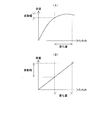
- the load characteristic of the leaf spring is different from the load characteristic of the disc spring, which exhibits nonlinear characteristics as shown in FIG. 8A, and has the linear characteristic shown in FIG. If the height changes even a little due to height variation or thermal expansion, the generated load fluctuates greatly. Therefore, in order to reduce the number of parts and cost, and to obtain nonlinear load characteristics, it is conceivable to make the outer periphery of the disc spring elliptical.
- Patent Documents 1 and 2 using a disc spring as an impact buffering means for the clutch mechanism propose that the outer periphery of the main body is elliptical.
- a disc spring is used as an impact buffering means for the clutch mechanism, and the main body and the hole of the disc spring are elliptical in order to improve the assembly of the disc spring to the clutch mechanism.
- the plate width is set equal in all of the disc spring main bodies.
- an annular groove is provided on the opposing surface of the piston on the friction plate side, and the inner peripheral portion of the hole of the disc spring is engaged with the annular groove.
- the long radius portion side curved portion is a portion on the long radius portion side having a small curvature radius, and is a portion within a predetermined angle range from the major axis in the elliptical outer peripheral portion, and the short radius portion side curved portion. Is a portion on the short radius side having a larger radius of curvature than the long radius portion side curved portion, and is a portion other than the long radius portion side curved portion in the elliptical outer peripheral portion.
- the present invention can deal with the rectangular shape of the arrangement space, and can obtain non-linear load characteristics as well as the stress difference between the long radius side curved portion and the short radius side curved portion.
- An object of the present invention is to provide an elliptical disc spring that can be reduced.
- the disc spring of the present invention includes a plate-shaped main body having an aperture and an elliptical outer periphery, and the plate width of the long radius portion of the main body is set larger than the plate width of the short radius portion of the main body. It is characterized by that.
- the long radius portion and the short radius portion are defined as follows.
- the portion having the maximum outer diameter (major axis) in the oval body is the long axis portion
- the portion having the minimum outer diameter (minor axis) in the ellipse body is the short axis portion.
- Each of the shaft portion and the short shaft portion is symmetric with respect to the center of the ellipse.
- the long radius part is each part obtained by dividing the long axis part at the center of the ellipse
- the short radius part is each part obtained by dividing the short axis part at the center of the ellipse.
- the plate width of the long radius portion is 1/2 of the difference between the outer diameter (long diameter) and the inner diameter of the long shaft portion
- the plate width of the short radius portion is the outer diameter (short diameter) of the short shaft portion. )
- the inner diameter is 1/2 of the difference between the outer diameter (long diameter) and the inner diameter of the long shaft portion
- the plate width of the short radius portion is the outer diameter (short diameter) of the short shaft portion.
- the disc spring of the present invention has a disc-shaped main body, a non-linear load characteristic can be obtained like a conventional disc spring having a circular outer periphery.
- the outer periphery of the main body has an elliptical shape and the major axis and the minor axis can be appropriately set, it is possible to correspond to a rectangular arrangement space.
- the stress generated in the long radius side curved portion is larger in the radius of curvature than the long radius side curved portion.
- the disc spring of the present invention since the plate width of the long radius portion is set larger than the plate width of the short radius portion, the long radius portion side curve The stress difference between the portion and the short radius portion curved portion can be reduced. As a result, the generated stress can be made uniform in the circumferential direction of the main body. Therefore, unlike the conventional elliptical disc spring, it is possible to set a large stroke application range (load) without being limited by the stress at the long radius side curved portion with a small curvature radius.
- the disc spring of the present invention can have various configurations.
- a mode in which the inner diameter of the long shaft portion is set to be equal to or larger than the inner diameter of the short shaft portion can be used.
- the stress difference between the long radius portion side curved portion and the short radius portion side curved portion can be effectively reduced, and the generated stress can be effectively uniformed in the circumferential direction of the main body.
- the disc spring of the present invention it is possible to correspond to the rectangular shape of the arrangement space, and it is possible to obtain non-linear load characteristics, as well as between the long radius portion side curved portion and the short radius portion side curved portion. Effects such as a reduction in stress difference can be obtained.
- FIG. 1A shows a configuration of a disc spring according to an embodiment of the present invention, wherein (A) is a top view of a disc spring, a lower view is an axial sectional view of a long shaft portion of the disc spring, and a right view is a disc spring. Sectional drawing of the axial direction of a short shaft part, (B) is a top view of a part of a disc spring. (A), (B) is a top view showing the structure of the modification of the disc spring which concerns on one Embodiment of this invention. It is a top view of the elliptical disc spring of the example of the present invention provided on the arrangement space.
- FIG. 1B are diagrams illustrating the configuration of an elliptical disc spring according to an embodiment of the present invention.
- the XY coordinate system is set, the center of the ellipse is set as the origin of the XY coordinate system, and the part having the major axis of the ellipse (major axis part) is set in the X-axis direction.
- the part (short axis part) which has an elliptical minor axis is set to the Y-axis direction. Since the elliptical disc spring 100 has a symmetrical shape with respect to each of the X axis and the Y axis, only the first quadrant of the XY coordinate system is shown in FIG. 1B for convenience of illustration.
- the elliptical disc spring 100 is used for various applications such as a pressing unit and an impact buffering unit.
- An elliptical disc spring 100 (disc spring) includes a main body 110 having a disc shape (substantially conical shape) and an outer periphery being elliptical as shown in FIGS. 1 (A) and 1 (B), for example.
- a hole 110 ⁇ / b> A is formed at the center of the main body 110.
- the main body 110 has a long radius portion 111 and a short radius portion 112.
- the long radius portion 111 is an X-axis plus direction portion and an X-axis minus direction portion obtained by dividing the long axis portion at the origin 0 (ellipse center) of the coordinate system.
- the short radius portion 112 is a Y-axis plus direction portion and a Y-axis minus direction portion obtained by dividing the short axis portion at the origin 0 (ellipse center) of the coordinate system.
- the plate width of the predetermined part of the main body is the outer diameter (interval of the intersection of the straight line passing through the center of the ellipse and the outer periphery of the ellipse) and the inner diameter (straight line passing through the center of the ellipse and the inner circumference of the ellipse) Of the difference between the crossing points and the part).
- the long radius portion side bending portion 111A shown in FIG. 1B is a bending portion on the long radius portion 111 side, and is within a range of a predetermined angle from the X axis in the outer peripheral portion of the main body 110 (for example, with reference to the X axis). 0 to ⁇ (°).
- the short radius portion side curved portion 112A shown in FIG. 1B is a curved portion on the short radius portion 112 side, and a portion other than the long radius portion side curved portion 111A in the outer peripheral portion of the main body 110 (for example, the Y axis
- the plate width a of the long radius portion 111 is set to be larger than the plate width b of the short radius portion 112 as described above.
- the plate width decreases from the long radius portion 111 toward the short radius portion 112.
- the height is set to H and the plate thickness is set to T.
- the height H can be appropriately set according to the application.
- the hole 110A has an elliptical shape.
- the inner diameter Dai of the long shaft portion is set smaller than the inner diameter Dbi of the short shaft portion (that is, Dai ⁇ Dbi).
- the inner diameter Dai of the long shaft portion is set larger than the inner diameter Dbi of the short shaft portion (that is, Dai> Dbi).
- the inner diameter Dai of the long shaft portion is preferably set to be equal to or larger than the inner diameter Dbi of the short shaft portion (that is, Dai ⁇ Dbi).
- the shape of the hole 110A it is preferable to set the shape of the hole 110A to be elliptic when engaging the inner peripheral portion of the hole 110A with the annular groove on the opposed surface of the piston. is there.
- a method for manufacturing the elliptical disc spring 100 will be described. First, an elliptical blank (elliptical blank) having a hole in the center is punched out of a plate material having a thickness T by, for example, pressing. Next, the elliptical blank is formed into a dish shape by bending the elliptical blank, for example. Subsequently, if necessary, the dish-shaped elliptical blank 100 (plate thickness T, height H) is obtained by performing heat treatment on the dish-shaped elliptical blank as necessary. In addition, you may perform the bending process to a blank, and heat processing simultaneously.
- a known disc spring manufacturing method can be used within the scope of the present invention.
- the dish-shaped main body 110 since the dish-shaped main body 110 is provided, a non-linear load characteristic can be obtained in the same manner as a conventional disk spring having a circular outer periphery. Moreover, since the outer periphery of the main body 110 has an elliptical shape and the major axis and the minor axis can be set as appropriate, it can correspond to a rectangular arrangement space.
- the elliptical disc spring 100 of the present invention example shown in FIG. 3 was used, and the three disc springs 1 of the comparative example shown in FIG. 7B were used.
- the major axis was set to 60 mm
- the minor axis was set to 23.5 mm
- the plate width a of the long radius portion was set larger than the plate width b of the short radius portion.
- the outer diameter was set to 23.5 mm
- the inner diameter was set to 16 mm.
- the elliptical disc spring 100 according to the present invention had three discs according to the comparative example.
- the characteristic was almost the same as that of the spring 1.
- the elliptical disc spring 100 can obtain nonlinear load characteristics. Therefore, when used as a pressing means for semiconductor elements, the height of the elliptical disk spring 100 varies depending on the height between the semiconductor elements or due to thermal expansion. Even if it changes, the fluctuation
- the plate width a of the long radius portion 111 is set to be larger than the plate width b of the short radius portion 112, so that the long radius portion side curved portion 111A and the short radius portion side curved portion 112A Can be reduced, and as a result, the generated stress can be made uniform in the circumferential direction of the main body 110.
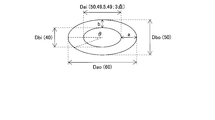
- the outer diameter Dao (longer diameter) of the long shaft portion, the outer diameter Dbo (short diameter) of the short shaft portion, and the inner diameter Dbi of the short shaft portion are kept constant.
- the inner diameter Dai of the long axis portion was changed, and the generated stress at the outer peripheral edge portion was examined. In this case, 21 points of generated stress data were obtained at regular intervals within an angle ⁇ of 0 to 90 °.
- the outer diameter Dao of the long shaft portion was set to 60 mm
- the outer diameter Dbo of the short shaft portion was set to 50 mm
- the inner diameter Dbi of the short shaft portion was set to 40 mm.
- the plate width b of the short radius portion was constant at 5 mm.
- the inner diameter Dai of the long shaft part of the elliptical disc spring of Example 11 of the present invention was set to 49.5 mm (that is, the plate width a of the long radius part was 5.25 mm).
- the inner diameter Dai of the long shaft portion of the elliptical disc spring of Example 12 of the present invention is 49 mm (that is, the plate width a of the long radius portion is 5.5 mm), and the inner diameter Dai of the long shaft portion of the elliptical disc spring of Comparative Example 11 is 50 mm ( That is, the plate width a of the long radius portion was set to 5 mm).
- FIG. 6 is a graph showing the relationship between the angle ⁇ and the generated stress obtained for the elliptical disc springs of Examples 11 and 12 of the present invention and Comparative Example 11.
- the angle 0 ° is the long axis position at the long radius portion side curved portion
- the angle 90 ° is the short axis position at the short radius portion side curved portion.
- the generated stress is usually uniform in the circumferential direction of the main body.
- the plate width a of the long radius portion and the plate width b of the short radius portion are set equal.
- the stress generated in the long radius portion side curved portion was higher than that in the short radius portion side curved portion, and the stress difference was large.
- the plate width “a” of the long radius portion is set larger than the plate width “b” of the short radius portion, the stress generated in the long radius portion curved portion is reduced and the stress difference is reduced.
- inventive examples 11 and 12 within the scope of the present invention reduce the stress difference between the long radius portion side curved portion and the short radius portion side curved portion as compared with the comparative example 11 outside the scope of the present invention. I confirmed that I was able to.
- the stress difference between the long radius portion side curved portion 111A and the short radius portion side curved portion 112A can be reduced. Uniformity can be achieved. Therefore, unlike the conventional elliptical disc spring, the stroke application range (load) can be set large without being limited by the stress of the long radius portion curved portion 111A having a small curvature radius.
- the stress difference between the long radius portion side curved portion 111A and the short radius portion side curved portion 112A can be effectively reduced.
- the generated stress can be effectively uniformed in the circumferential direction of the main body 110.
- SYMBOLS 100 Elliptical disc spring (disc spring), 110 ... Main body, 110A ... Hole part, 111 ... Long radius part, 112 ... Short radius part, a ... Plate width of a long radius part, b ... Plate width of a short radius part, 111A ... long radius part curved part, 112A ... short radius part curved part, Dai ... inner diameter of major axis part, Dbi ... inner diameter of minor axis part
Landscapes
- Engineering & Computer Science (AREA)
- General Engineering & Computer Science (AREA)
- Mechanical Engineering (AREA)
- Springs (AREA)
Description
以下、本発明の一実施形態について図面を参照して説明する。図1,2は、本発明の一実施形態に係る楕円皿ばねの構成を表す図である。なお、図1(B)では、XY座標系を設定し、楕円の中心をXY座標系の原点に設定し、楕円形の長径を有している部分(長軸部)をX軸方向に設定し、楕円形の短径を有している部分(短軸部)をY軸方向に設定している。楕円皿ばね100は、X軸およびY軸のそれぞれに関して対称な形状をなすから、図1(B)では、図示の便宜上、XY座標系の第1象限のみを図示している。
Claims (2)
- 孔部を有するとともに、外周が楕円形をなす皿形状の本体を備え、
前記本体の長半径部の板幅が前記本体の短半径部の板幅よりも大きく設定されていることを特徴とする皿ばね。 - 長軸部の内径が短軸部の内径以上に設定されていることを特徴とする請求項1に記載の皿ばね。
Priority Applications (3)
| Application Number | Priority Date | Filing Date | Title |
|---|---|---|---|
| JP2014506309A JP6042411B2 (ja) | 2012-03-23 | 2013-03-25 | 皿ばね |
| CN201380015979.3A CN104204600A (zh) | 2012-03-23 | 2013-03-25 | 盘簧 |
| US14/387,372 US9400027B2 (en) | 2012-03-23 | 2013-03-25 | Coned disc spring |
Applications Claiming Priority (2)
| Application Number | Priority Date | Filing Date | Title |
|---|---|---|---|
| JP2012066878 | 2012-03-23 | ||
| JP2012-066878 | 2012-03-23 |
Publications (1)
| Publication Number | Publication Date |
|---|---|
| WO2013141401A1 true WO2013141401A1 (ja) | 2013-09-26 |
Family
ID=49222844
Family Applications (1)
| Application Number | Title | Priority Date | Filing Date |
|---|---|---|---|
| PCT/JP2013/058570 Ceased WO2013141401A1 (ja) | 2012-03-23 | 2013-03-25 | 皿ばね |
Country Status (4)
| Country | Link |
|---|---|
| US (1) | US9400027B2 (ja) |
| JP (1) | JP6042411B2 (ja) |
| CN (1) | CN104204600A (ja) |
| WO (1) | WO2013141401A1 (ja) |
Cited By (4)
| Publication number | Priority date | Publication date | Assignee | Title |
|---|---|---|---|---|
| JP2017180745A (ja) * | 2016-03-31 | 2017-10-05 | 株式会社ショーワ | 圧力緩衝装置 |
| CN108061119A (zh) * | 2018-01-22 | 2018-05-22 | 廊坊双飞碟簧有限公司 | 一种线性碟形弹簧 |
| WO2018235394A1 (ja) * | 2017-06-21 | 2018-12-27 | 三菱重工航空エンジン株式会社 | 応力低減構造、ガスタービンケーシングおよびガスタービン |
| JP7514179B2 (ja) | 2020-12-14 | 2024-07-10 | セイコーウオッチ株式会社 | 針座保持構造、時計用ムーブメントおよび時計 |
Families Citing this family (24)
| Publication number | Priority date | Publication date | Assignee | Title |
|---|---|---|---|---|
| DE102016104840A1 (de) * | 2016-03-16 | 2017-09-21 | Elringklinger Ag | Ventilvorrichtung für einen Turbolader |
| CN110192052B (zh) | 2017-01-26 | 2020-09-22 | 伊格尔工业股份有限公司 | 容量控制阀 |
| US11542930B2 (en) | 2017-02-18 | 2023-01-03 | Eagle Industry Co., Ltd. | Capacity control valve |
| CN114687984B (zh) | 2017-11-15 | 2024-12-31 | 伊格尔工业股份有限公司 | 容量控制阀 |
| JP7083844B2 (ja) | 2017-11-30 | 2022-06-13 | イーグル工業株式会社 | 容量制御弁及び容量制御弁の制御方法 |
| KR102441855B1 (ko) | 2017-12-08 | 2022-09-08 | 이구루코교 가부시기가이샤 | 용량 제어 밸브 및 용량 제어 밸브의 제어 방법 |
| US11542929B2 (en) | 2017-12-14 | 2023-01-03 | Eagle Industry Co., Ltd. | Capacity control valve and method for controlling capacity control valve |
| US11434885B2 (en) * | 2017-12-27 | 2022-09-06 | Eagle Industry Co., Ltd. | Capacity control valve and method for controlling same |
| WO2019131694A1 (ja) | 2017-12-27 | 2019-07-04 | イーグル工業株式会社 | 容量制御弁及び容量制御弁の制御方法 |
| CN111630270B (zh) | 2018-01-22 | 2022-04-15 | 伊格尔工业股份有限公司 | 容量控制阀 |
| EP3889430B1 (en) | 2018-11-26 | 2024-07-17 | Eagle Industry Co., Ltd. | Capacity control valve |
| CN109914190A (zh) * | 2019-04-01 | 2019-06-21 | 江苏亿之博实业有限公司 | 球场用人造草坪基布及其使用方法 |
| EP4191102A4 (en) | 2020-08-03 | 2024-08-21 | Eagle Industry Co., Ltd. | VALVE |
| WO2022030315A1 (ja) | 2020-08-04 | 2022-02-10 | イーグル工業株式会社 | 膨張弁 |
| CN116134254B (zh) | 2020-08-04 | 2025-11-07 | 伊格尔工业股份有限公司 | 阀 |
| WO2022030312A1 (ja) | 2020-08-04 | 2022-02-10 | イーグル工業株式会社 | 弁 |
| CN116097026B (zh) | 2020-08-24 | 2025-11-11 | 伊格尔工业股份有限公司 | 阀 |
| KR102879499B1 (ko) | 2020-09-28 | 2025-10-31 | 이구루코교 가부시기가이샤 | 밸브 |
| CN116324245A (zh) | 2020-10-01 | 2023-06-23 | 伊格尔工业股份有限公司 | 流体控制阀 |
| CN116457592A (zh) | 2020-10-01 | 2023-07-18 | 伊格尔工业股份有限公司 | 阀 |
| WO2022131053A1 (ja) | 2020-12-17 | 2022-06-23 | イーグル工業株式会社 | 弁 |
| CN117098943A (zh) | 2021-03-29 | 2023-11-21 | 伊格尔工业股份有限公司 | 阀 |
| WO2022255188A1 (ja) | 2021-05-31 | 2022-12-08 | イーグル工業株式会社 | 流体制御弁 |
| JPWO2023033143A1 (ja) | 2021-09-02 | 2023-03-09 |
Citations (2)
| Publication number | Priority date | Publication date | Assignee | Title |
|---|---|---|---|---|
| JPS6435133A (en) * | 1987-07-28 | 1989-02-06 | Saginomiya Seisakusho Inc | Manufacture of circular resilient plate |
| JPH0725533U (ja) * | 1993-10-14 | 1995-05-12 | 日本航空電子工業株式会社 | シート状皿バネ |
Family Cites Families (11)
| Publication number | Priority date | Publication date | Assignee | Title |
|---|---|---|---|---|
| DE3246201A1 (de) | 1982-12-14 | 1984-06-14 | Wabco Westinghouse Fahrzeugbremsen GmbH, 3000 Hannover | Verfahren und einrichtung zur ermittlung des gewichtes eines fahrzeuges |
| JPH0438127Y2 (ja) | 1985-08-24 | 1992-09-07 | ||
| US6050557A (en) * | 1995-08-28 | 2000-04-18 | Mitsubshi Steel Mfg. Co., Ltd. | Coiled disk spring |
| JP3526745B2 (ja) * | 1998-06-11 | 2004-05-17 | 株式会社牧野フライス製作所 | 皿ばね及びその皿ばねを用いた主軸装置 |
| JP2000193001A (ja) * | 1998-12-25 | 2000-07-14 | Ohbayashi Corp | コンクリ―ト製皿ばね及びこれを用いた免振支承構造 |
| JP4065178B2 (ja) * | 2002-10-24 | 2008-03-19 | 株式会社エフ・シー・シー | 多板摩擦式クラッチ |
| US7740321B2 (en) * | 2006-05-12 | 2010-06-22 | Herman Miller, Inc. | Suspended pixelated seating structure |
| DE102008006065B4 (de) * | 2007-02-15 | 2022-04-14 | Schaeffler Technologies AG & Co. KG | Verfahren zur Herstellung einer Tellerfeder |
| JP4815469B2 (ja) * | 2008-05-13 | 2011-11-16 | 日本発條株式会社 | ばね |
| JP5456396B2 (ja) * | 2009-07-13 | 2014-03-26 | 中央発條株式会社 | 皿ばね及びその製造方法 |
| WO2013062555A2 (en) * | 2011-10-27 | 2013-05-02 | Mw Industries, Inc. | Coned-disc spring device, spring assembly, and methods of making the same |
-
2013
- 2013-03-25 CN CN201380015979.3A patent/CN104204600A/zh active Pending
- 2013-03-25 JP JP2014506309A patent/JP6042411B2/ja active Active
- 2013-03-25 US US14/387,372 patent/US9400027B2/en active Active
- 2013-03-25 WO PCT/JP2013/058570 patent/WO2013141401A1/ja not_active Ceased
Patent Citations (2)
| Publication number | Priority date | Publication date | Assignee | Title |
|---|---|---|---|---|
| JPS6435133A (en) * | 1987-07-28 | 1989-02-06 | Saginomiya Seisakusho Inc | Manufacture of circular resilient plate |
| JPH0725533U (ja) * | 1993-10-14 | 1995-05-12 | 日本航空電子工業株式会社 | シート状皿バネ |
Cited By (6)
| Publication number | Priority date | Publication date | Assignee | Title |
|---|---|---|---|---|
| JP2017180745A (ja) * | 2016-03-31 | 2017-10-05 | 株式会社ショーワ | 圧力緩衝装置 |
| WO2018235394A1 (ja) * | 2017-06-21 | 2018-12-27 | 三菱重工航空エンジン株式会社 | 応力低減構造、ガスタービンケーシングおよびガスタービン |
| JP2019007368A (ja) * | 2017-06-21 | 2019-01-17 | 三菱重工航空エンジン株式会社 | 応力低減構造、ガスタービンケーシングおよびガスタービン |
| US11168586B2 (en) | 2017-06-21 | 2021-11-09 | Mitsubishi Heavy Industries Aero Engines, Ltd. | Stress reduction structure, gas turbine casing, and gas turbine |
| CN108061119A (zh) * | 2018-01-22 | 2018-05-22 | 廊坊双飞碟簧有限公司 | 一种线性碟形弹簧 |
| JP7514179B2 (ja) | 2020-12-14 | 2024-07-10 | セイコーウオッチ株式会社 | 針座保持構造、時計用ムーブメントおよび時計 |
Also Published As
| Publication number | Publication date |
|---|---|
| JP6042411B2 (ja) | 2016-12-14 |
| US9400027B2 (en) | 2016-07-26 |
| JPWO2013141401A1 (ja) | 2015-08-03 |
| US20150076756A1 (en) | 2015-03-19 |
| CN104204600A (zh) | 2014-12-10 |
Similar Documents
| Publication | Publication Date | Title |
|---|---|---|
| JP6042411B2 (ja) | 皿ばね | |
| CN104011798B (zh) | 公差环 | |
| JP2012531568A (ja) | ロックナット | |
| US10487845B2 (en) | Fan structure and manufacturing method thereof | |
| JPWO2015194196A1 (ja) | 皿ばね | |
| JP2017526878A (ja) | トレランスリング | |
| US9334763B1 (en) | Support pin for spring guidance in a camshaft phaser | |
| US8567584B2 (en) | Friction plate with pressed core plates | |
| CN106030154B (zh) | 滚珠丝杠装置 | |
| JP2015178851A (ja) | ダンパ装置 | |
| WO2010073918A1 (ja) | ばね | |
| JP2006288060A (ja) | 振動波駆動装置及び該振動波駆動装置を備える機器 | |
| JP6292293B2 (ja) | ダンパ装置 | |
| JPWO2014136878A1 (ja) | 締付構造および締付方法 | |
| JP4849508B2 (ja) | 平面に凹凸部を有する円板部材の誘導加熱焼入れ方法及び誘導加熱焼入用コイル。 | |
| JP2017020576A (ja) | 皿ばね | |
| JP6557001B2 (ja) | 捩り振動低減装置 | |
| JP5819253B2 (ja) | 皿ばね | |
| TWI404321B (zh) | 一種具有預壓元件之三自由度球狀超音波馬達裝置 | |
| JP7202779B2 (ja) | 電動機 | |
| JP5914518B2 (ja) | 取付具 | |
| JP2015035918A (ja) | ロータ | |
| JP5827637B2 (ja) | コイルばね | |
| WO2011129208A1 (ja) | ばね | |
| JP2025084186A (ja) | ステータ構造 |
Legal Events
| Date | Code | Title | Description |
|---|---|---|---|
| 121 | Ep: the epo has been informed by wipo that ep was designated in this application |
Ref document number: 13764801 Country of ref document: EP Kind code of ref document: A1 |
|
| ENP | Entry into the national phase |
Ref document number: 2014506309 Country of ref document: JP Kind code of ref document: A |
|
| WWE | Wipo information: entry into national phase |
Ref document number: 14387372 Country of ref document: US |
|
| NENP | Non-entry into the national phase |
Ref country code: DE |
|
| 122 | Ep: pct application non-entry in european phase |
Ref document number: 13764801 Country of ref document: EP Kind code of ref document: A1 |