WO2019004158A1 - シリンジの開封確認構造 - Google Patents
シリンジの開封確認構造 Download PDFInfo
- Publication number
- WO2019004158A1 WO2019004158A1 PCT/JP2018/024092 JP2018024092W WO2019004158A1 WO 2019004158 A1 WO2019004158 A1 WO 2019004158A1 JP 2018024092 W JP2018024092 W JP 2018024092W WO 2019004158 A1 WO2019004158 A1 WO 2019004158A1
- Authority
- WO
- WIPO (PCT)
- Prior art keywords
- syringe
- nozzle
- lock member
- axial direction
- rotation
- Prior art date
- Legal status (The legal status is an assumption and is not a legal conclusion. Google has not performed a legal analysis and makes no representation as to the accuracy of the status listed.)
- Ceased
Links
Images




Classifications
-
- A—HUMAN NECESSITIES
- A61—MEDICAL OR VETERINARY SCIENCE; HYGIENE
- A61M—DEVICES FOR INTRODUCING MEDIA INTO, OR ONTO, THE BODY; DEVICES FOR TRANSDUCING BODY MEDIA OR FOR TAKING MEDIA FROM THE BODY; DEVICES FOR PRODUCING OR ENDING SLEEP OR STUPOR
- A61M5/00—Devices for bringing media into the body in a subcutaneous, intra-vascular or intramuscular way; Accessories therefor, e.g. filling or cleaning devices, arm-rests
- A61M5/50—Devices for bringing media into the body in a subcutaneous, intra-vascular or intramuscular way; Accessories therefor, e.g. filling or cleaning devices, arm-rests having means for preventing re-use, or for indicating if defective, used, tampered with or unsterile
-
- A—HUMAN NECESSITIES
- A61—MEDICAL OR VETERINARY SCIENCE; HYGIENE
- A61M—DEVICES FOR INTRODUCING MEDIA INTO, OR ONTO, THE BODY; DEVICES FOR TRANSDUCING BODY MEDIA OR FOR TAKING MEDIA FROM THE BODY; DEVICES FOR PRODUCING OR ENDING SLEEP OR STUPOR
- A61M5/00—Devices for bringing media into the body in a subcutaneous, intra-vascular or intramuscular way; Accessories therefor, e.g. filling or cleaning devices, arm-rests
- A61M5/50—Devices for bringing media into the body in a subcutaneous, intra-vascular or intramuscular way; Accessories therefor, e.g. filling or cleaning devices, arm-rests having means for preventing re-use, or for indicating if defective, used, tampered with or unsterile
- A61M5/5086—Devices for bringing media into the body in a subcutaneous, intra-vascular or intramuscular way; Accessories therefor, e.g. filling or cleaning devices, arm-rests having means for preventing re-use, or for indicating if defective, used, tampered with or unsterile for indicating if defective, used, tampered with or unsterile
-
- A—HUMAN NECESSITIES
- A61—MEDICAL OR VETERINARY SCIENCE; HYGIENE
- A61M—DEVICES FOR INTRODUCING MEDIA INTO, OR ONTO, THE BODY; DEVICES FOR TRANSDUCING BODY MEDIA OR FOR TAKING MEDIA FROM THE BODY; DEVICES FOR PRODUCING OR ENDING SLEEP OR STUPOR
- A61M5/00—Devices for bringing media into the body in a subcutaneous, intra-vascular or intramuscular way; Accessories therefor, e.g. filling or cleaning devices, arm-rests
- A61M5/178—Syringes
- A61M5/31—Details
-
- A—HUMAN NECESSITIES
- A61—MEDICAL OR VETERINARY SCIENCE; HYGIENE
- A61M—DEVICES FOR INTRODUCING MEDIA INTO, OR ONTO, THE BODY; DEVICES FOR TRANSDUCING BODY MEDIA OR FOR TAKING MEDIA FROM THE BODY; DEVICES FOR PRODUCING OR ENDING SLEEP OR STUPOR
- A61M5/00—Devices for bringing media into the body in a subcutaneous, intra-vascular or intramuscular way; Accessories therefor, e.g. filling or cleaning devices, arm-rests
- A61M5/178—Syringes
- A61M5/31—Details
- A61M5/32—Needles; Details of needles pertaining to their connection with syringe or hub; Accessories for bringing the needle into, or holding the needle on, the body; Devices for protection of needles
- A61M5/3202—Devices for protection of the needle before use, e.g. caps
-
- A—HUMAN NECESSITIES
- A61—MEDICAL OR VETERINARY SCIENCE; HYGIENE
- A61M—DEVICES FOR INTRODUCING MEDIA INTO, OR ONTO, THE BODY; DEVICES FOR TRANSDUCING BODY MEDIA OR FOR TAKING MEDIA FROM THE BODY; DEVICES FOR PRODUCING OR ENDING SLEEP OR STUPOR
- A61M5/00—Devices for bringing media into the body in a subcutaneous, intra-vascular or intramuscular way; Accessories therefor, e.g. filling or cleaning devices, arm-rests
- A61M5/178—Syringes
- A61M5/31—Details
- A61M2005/3103—Leak prevention means for distal end of syringes, i.e. syringe end for mounting a needle
- A61M2005/3104—Caps for syringes without needle
-
- A—HUMAN NECESSITIES
- A61—MEDICAL OR VETERINARY SCIENCE; HYGIENE
- A61M—DEVICES FOR INTRODUCING MEDIA INTO, OR ONTO, THE BODY; DEVICES FOR TRANSDUCING BODY MEDIA OR FOR TAKING MEDIA FROM THE BODY; DEVICES FOR PRODUCING OR ENDING SLEEP OR STUPOR
- A61M2205/00—General characteristics of the apparatus
- A61M2205/27—General characteristics of the apparatus preventing use
- A61M2205/273—General characteristics of the apparatus preventing use preventing reuse, e.g. of disposables
Definitions
- the present invention relates to an opening confirmation structure of a syringe for enabling confirmation of an opening state.
- a cap is attached to a nozzle in consideration of safety and hygiene in the syringe.
- some of such syringes with a cap have an opening confirmation structure (so-called tamper-evident structure) for confirming that they have been opened once.
- the opening confirmation structure disclosed in Patent Document 1 includes a cylindrical adapter fixed around a nozzle of a syringe, a closing body externally fitted to the adapter in a state of covering the nozzle, and an annular tear that surrounds the adapter. And an open ring, the split ring being releasably connected to the closure.
- one open end in the axial direction (hereinafter referred to as the first open end) is disposed on the tip side of the nozzle, and the other open end in the axial direction (hereinafter referred to as the second open end) It is arranged on the part side.
- a helical thread is formed on the outer peripheral surface on the first open end side of the adapter, and a flange projecting radially outward from the outer peripheral surface is formed on the second open end side of the adapter ing.
- the closing body is cylindrical, and only one end in the axial direction is open. Further, an internal thread is formed on the inner peripheral surface at one end side of the closing body.
- the split ring is releasably connected to one end of the closure.
- the tear-off ring passes over the flange as the closure is tightened on the adapter, the tear-off ring is held against the adapter by the flange.
- the closing body When opening the syringe, when the closing body is rotated (rotational operation in a direction to loosen the adapter), the closing body is moved in the direction away from the tearing ring in the axial direction along with the rotation. Then, as the closing body continues to be turned, the closing body and the split ring are separated, and the closing body is detached from the adapter.
- the opening confirmation structure of the above configuration has a structure in which the closing body and the split ring are separated at the time of opening the syringe, by confirming the connection state of the close body and the split ring, It is possible to grasp the opening status.
- the above-mentioned conventional opening confirmation structure is configured to screw the closing body to the adapter, even after opening the syringe, when the closing body is tightened to the adapter again, the closing body It will be fixed at the position before opening. Therefore, there is a possibility that the positional relationship between the closing body and the split ring returns to the state before the opening, and the user may misidentify the opening state of the syringe.
- this invention makes it a subject to provide the opening confirmation structure of the syringe which can be made to be able to recognize at one glance that it has been opened in view of this situation.
- the opening confirmation structure of the syringe of the present invention is With a cap attached to the syringe,
- the cap has a cover for covering the tip of the nozzle, a plug having elasticity and sealing the tip of the nozzle in a state of being attached to the cover, and being cylindrical and having the nozzle inside And a tamper ring fixed to the syringe in the inserted state;
- the cover portion is configured to be elastically compressed by pressing the close plug portion against the tip of the nozzle in the axial direction of the tamper ring.
- the tamper ring has a constraining portion that is disconnectably connected to the cover portion.
- the opening confirmation structure of the syringe of the present invention is It has a lock member which is cylindrical and fixed to the syringe in a state where the nozzle is inserted therethrough, The lock member is insertable into the tamper ring in the axial direction, and the locking engagement portion is engaged with the inner peripheral surface of the tamper ring and the outer peripheral surface of the lock member in the axial direction. May be formed.
- the opening confirmation structure of the syringe of the present invention is A rotation stopping structure for preventing rotation of the tamper ring in a circumferential direction around the axial direction;
- the rotation stopping structure has a first rotation engagement portion formed on the syringe and a second rotation engagement portion formed on the tamper ring, The first engagement portion for locking and the second engagement portion for locking may be engageable with each other in the circumferential direction.
- the lock member may be configured to have a rotation stopping contact portion that can be in contact with the locking engagement portion of the tamper ring in a circumferential direction around the axial direction.
- the lock member has a fixed portion screwed into a cylindrical peripheral wall portion formed around the nozzle in a state of being inserted into the nozzle,
- the lock member may be provided with a rotation preventing portion for preventing rotation with respect to the peripheral wall portion.
- FIG. 1 is a perspective view of a capped syringe according to an embodiment of the present invention.
- FIG. 2 is an exploded view of a capped syringe according to the same embodiment.
- FIG. 3 is an enlarged view of the lock member and the syringe of the capped syringe according to the same embodiment.
- FIG. 4 is a cross-sectional view of the cap taken along line IV-IV of FIG.
- FIG. 5 is an enlarged cross-sectional view of the capped syringe taken along line VV of FIG.
- FIG. 6 is an explanatory view of a capped syringe before opening.
- FIG. 7 is an explanatory view of a capped syringe after opening.
- FIG. 1 is a perspective view of a capped syringe according to an embodiment of the present invention.
- FIG. 2 is an exploded view of a capped syringe according to the same embodiment.
- FIG. 3 is
- FIG. 8 is an explanatory view of a capped syringe in a state in which the nozzle is covered with a hermetic plug after opening.
- FIG. 9 is a longitudinal sectional view of a cap and a tamper ring of a capped syringe according to another embodiment of the present invention.
- FIG. 10 is an enlarged vertical cross-sectional view of the capped syringe according to the embodiment.
- FIG. 11 is an enlarged view of a main part of a capped syringe according to another embodiment of the present invention.
- the syringe 2 is equipped with the outer cylinder 20 with which liquids, such as a chemical
- a plunger may be attached to the outer cylindrical body 20.
- the outer cylindrical body 20 is provided on the barrel 200 so as to surround the cylindrical barrel 200, the nozzle 201 provided at one end in the axial direction of the barrel 200, and the nozzle 201. And a rotation preventing rib 203 formed on the outside of the peripheral wall portion 202.
- the barrel 200 is cylindrical and has a cylindrical portion 200a whose outer diameter and inner diameter are the same or substantially the same over the entire length in the axial direction, and extends from one end in the axial direction of the cylindrical portion 200a. And a shoulder 200b formed to have a gradually decreasing outer diameter.
- the axial direction of the barrel 200 (cylindrical portion 200a) is simply referred to as the axial direction
- the direction orthogonal to the axial direction is referred to as the radial direction
- the circumferential direction centered on the axial direction is simply circumferential. The following description will be made by referring to the direction.
- the nozzle 201 is extended at the tip of the shoulder portion 200b, and is formed so that the outer diameter is smaller than the outer diameters of the cylindrical portion 200a and the shoulder portion 200b. Further, the nozzle 201 is formed in a hollow cylindrical shape, and the opening on the proximal end in the direction extending from the shoulder 200 b is continuous with the inside of the barrel 200, and the opening on the distal end in the extending direction is outside It is open to the public.
- the peripheral wall portion 202 is an annular (in this embodiment, annular) peripheral wall main body portion 202a extending from the shoulder portion 200b in the axial direction, and a lock member 3 described later fixed to the peripheral wall main body portion 202a. And the fixed part 202b of
- the outer diameter of the peripheral wall portion 202 is smaller than the outer diameter of the cylindrical portion 200a. Therefore, the outer peripheral surface of the peripheral wall portion 202 is located inward in the radial direction with respect to the outer peripheral surface of the cylindrical portion 200a, and a step is formed between the cylindrical portion 200a and the peripheral wall portion 202. There is.
- the inner diameter of the peripheral wall portion 202 is larger than the outer diameter of the nozzle 201. Therefore, a space is formed between the inner peripheral surface of the peripheral wall portion 202 and the outer peripheral surface of the nozzle 201.
- the fixing portion 202b is constituted by a female screw formed on the inner peripheral surface of the peripheral wall main portion 202a, and can restrict movement of the lock member 3 in the axial direction.
- the rotation preventing rib 203 linearly extends along the axial direction, and in the present embodiment, extends along the axial direction from the tip of the peripheral wall main body portion 202a to the shoulder portion 200b. Further, in the present embodiment, a plurality (four) of the rotation preventing ribs 203 are arranged at intervals in the circumferential direction.
- the lock member 3 is a member formed in a tubular shape, and is configured to be able to be attached to the syringe 2 (the peripheral wall portion 202) in a state where the nozzle 201 is inserted from one opening (see FIG. 5). .
- the lock member 3 includes a fixed portion 30 fixed to the peripheral wall portion 202, a detaining portion 31 continuously provided to the fixed portion 30, and the fixed portion 30 via the detention portion 31. And a connecting portion 32 connected integrally with the
- the to-be-fixed part 30 is cylindrical, and the screw thread is formed in the outer peripheral surface. Therefore, the lock member 3 is attached to the peripheral wall portion 202 by screwing the fixed portion 30 to the fixing portion 202b.
- Retaining portion 31 is cylindrical, and the internal space communicates with the internal space of fixed portion 30.
- a concave engaging groove 310 is formed on the outer peripheral surface of the retaining portion 31.
- the engagement groove 310 is formed to be continuous over the entire circumference of the outer peripheral surface of the retaining portion 31, and one of the insides in the axial direction (that is, the groove width direction of the engagement groove 310).
- the side surface 311 extends outward in the radial direction from the bottom surface.
- a plurality of anti-rotation abutment portions 312 are formed to be spaced apart in the circumferential direction.
- Each locking abutment portion 312 is formed to block the inside of the engagement groove 310 in the circumferential direction.
- the connecting portion 32 is also cylindrical, and the internal space communicates with the internal space of the fixed portion 30 and the internal space of the retaining portion 31.
- the lock member 3 is the tip of the connection portion 32 (one end connected to the retention portion 31) in a state where the lock member 3 is attached to the syringe 2 (a state where the fixed portion 30 is attached to the fixing portion 202b)
- One end on the opposite side is arranged at a position shifted to the base end side of the nozzle 201 with respect to the tip end of the nozzle 201 in the axial direction.
- connection portion 32 is formed with an internal thread on the inner peripheral surface, and an external device (for example, an injection needle, a three-way stopcock, etc.) for connecting to the nozzle 201 can be attached using the internal thread. It has become.
- the lock member 3 according to the present embodiment is also an adapter for fixing the state in which the external device is connected to the nozzle 201.
- the cap 4 has a cover 5 for protecting the tip of the nozzle 201, a tamper ring 6 which is detachably connected to the cover 5, and the inside of the cover 5. And a closing plug 7 (see FIG. 5) for closing (closing) the opening at the tip of the nozzle 201.
- the cover unit 5 has a cylindrical exterior unit 50, a holding unit 51 for holding the hermetic plug 7 in the case 50, and a sealing unit held by the holding unit 51. And a pressing portion 52 for pressing (compression) 7 toward the tip of the nozzle 201 in the axial direction.
- the tip of the nozzle 201 is inserted into the exterior 50 from one opening.
- one end on one opening side of the exterior portion 50 is referred to as a base end, and the other end on the opening side is referred to as a tip.
- the outer diameter of the exterior portion 50 is the same as or substantially the same as the outer diameter of the cylindrical portion 200a. In the state where the cap 4 is attached to the syringe 2, the axial direction of the exterior unit 50 corresponds to the axial direction of the barrel 200.
- a plurality of holding parts 51 are provided on the inner peripheral surface of the base end side of the exterior part 50.
- the plurality of holding parts 51 are arranged at intervals in the circumferential direction.
- Each holding portion 51 protrudes from the inner circumferential surface of the exterior portion 50 inward in the radial direction.
- a region further inside than the tip of each holding portion 51 is referred to as an insertion region, and the following description will be made.
- the pressing portion 52 is located closer to the tip end of the cover 5 than the holding portion 51 in the axial direction. Further, the pressing portion 52 is formed to face the holding portion 51 side (the base end side of the cover portion 5) in the axial direction, and has a pressing surface 520 which extends in the radial direction.
- At least a portion of the pressing surface 520 is located further inside (the inner side in the radial direction) than the tip of the holding portion 51.
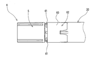
- the tamper ring 6 has a retaining ring 60 attached to the syringe 2, and a restraining portion 61 which protrudes from one open end of the retaining ring 60 and whose tip is detachably connected to the cover 5.
- a locking portion 62 provided at the other opening end of the locking ring 60, and a receiving portion 63 which protrudes from one opening end of the locking ring 60 and is aligned with the locking portion 61 in the circumferential direction.
- the retaining ring 60 has a plurality of engagement protrusions 600 provided on the inner circumferential surface.
- An engagement surface 600a which is formed on the distal end side of the cap 4 and which is a surface extending in the radial direction on the engagement projection 600, and the outer side in the radial direction from the engagement surface 600a to the base end side of the cap 4 It includes an inclined surface 600b formed so as to gradually go to the side.
- the restraint portion 61 is formed to be tapered. Further, in the present embodiment, the plurality of restraint portions 61 are formed to be arranged at predetermined intervals with respect to one open end of the retaining ring 60.
- One end (tip) in the axial direction of the detent portion 62 is provided at the other open end of the retaining ring 60. Further, an insertion groove 620 opened at the other end (proximal end) in the axial direction is formed in the rotation stopping portion 62.
- the insertion groove 620 extends along the axial direction. Further, the groove width on the bottom side of the insertion groove 620 is constant, and the groove width on the opening side of the insertion groove 620 gradually spreads away from the bottom side.
- bottom sides (hereinafter referred to as bottom side edges 621) of the pair of side edges of the insertion groove 620 extend parallel to each other along the axial direction, and the opening sides of the pair of side edges (hereinafter The opening side edges 622 are inclined so that the distance between them gradually spreads away from the bottom side.
- a plurality of receiving portions 63 are formed so as to line up with one opening end of the retaining ring 60 at predetermined intervals.
- the receiving portion 63 and the restraining portion 61 are alternately arranged with respect to one open end of the retaining ring 60.
- the amount of extension of the receiving portion 63 from the one open end is smaller than the amount of extension of the restraint portion 61. Therefore, the distal end of the receiving portion 63 is located closer to the tamper ring 6 than the distal end of the restraining portion 61, and in a state where the cover 5 is connected to the distal end of the restraining portion 61, A gap is formed between the receiving portion 63 and the receiving portion 63.
- Sealing part 7 has elasticity.
- the sealing plug 7 is integrally formed with a held portion 70 for holding the inside of the cover portion 5 and the held portion 70, and closes the opening at the tip of the nozzle 201.
- the holding portion 70 includes a head 700 disposed between the holding portion 51 and the pressing portion 52, and a plurality of holding portions 51 extending from the head 700 and being inserted into the insertion region. And an extended portion 701 to be held.
- the one end surface in the axial direction of the head 700 is an abutting surface 700 a that abuts on the pressing surface 520.
- the outer diameter of the extension portion 701 is smaller than the outer diameter of the head portion 700, and the outer peripheral surface of the extension portion 701 is located inside the outer peripheral surface of the head portion 700 over the entire circumference. .
- the closing portion 71 is formed with a press-fit recess 710 that opens toward the outside, and the tip end portion of the nozzle 201 is press-fit into the press-fit recess 710.
- the bottom surface 711 of the press-in recess 710 is in close contact with the tip end surface of the nozzle 201, and the inner circumferential surface 712 of the press-in recess 710 is in close contact with the outer circumferential surface of the nozzle 201.
- the size of the press-in recess 710 is smaller than the size of the nozzle 201.
- the configuration of the capped syringe 1 according to the present embodiment is as described above. Subsequently, how to assemble and use the capped syringe 1 will be described.
- the inside of the cap 4 in which the cover 5 and the tamper ring 6 are connected by the restraint 61 and in which the sealing plug 7 is attached is inserted.
- the tip of the nozzle 201 is press-fit into the press-fit recess 710 of the plug 7, the bottom surface 711 is in close contact with the tip surface of the nozzle 201, and the outer circumferential surface of the nozzle 201 is all around the inner periphery Faces 712 are in close proximity.
- the sealing plug 7 since the bottom surface 711 of the sealing plug 7 is pushed toward the pressing part 52 (the pressing surface 520) by the tip of the nozzle 201, the sealing plug 7 is in the axial direction by the pressing part 52 and the tip of the nozzle 201. Compressed with Therefore, the size (the distance D from the contact surface 700 a to the bottom surface 711) in the axial direction of the hermetic plug 7 is reduced.
- the engagement projection 600 engages. It fits in the grove 310.
- the inner side surface 311 in the engagement groove 310 and the engagement surface 600 a of the engagement protrusion 600 mutually engage in the axial direction, and the entire cap 4 is prevented from coming off the syringe 2.
- the inner side surface 311 of the engagement groove 310 and the engagement surface 600a of the engagement projection 600 become the engagement parts for disengagement engagement in the axial direction, and these engagement parts for disengagement prevent tampering.
- the ring 6 is locked to the lock member 3.
- the cover portion 5 holds the stopper plug 7 covering the tip end portion of the nozzle 201 in the axial direction while compressing the same in the axial direction, with respect to the tamper ring 6 fixed to the syringe 2 via the restraint portion 61. Connected.
- the rotation preventing rib 203 has the bottom side edge 621 and the opening side edge 622. And at positions adjacent to each other in the circumferential direction. Therefore, even if a rotational force acts on the cap 4, the rotation of the tamper ring 6 and the rotation stopping portion 62 with respect to the syringe 2 is caused by the interference between the locking rib 203 and the bottom side edge portion 621 in the circumferential direction. Is regulated.
- the syringe 2 or the tamper ring 6 When opening the capped syringe 1 manufactured as described above, the syringe 2 or the tamper ring 6 is held by one hand, and the cover 5 is twisted in the circumferential direction by the other hand for restraint. Since the cover 5 is separated from the tamper ring 6 when the part 61 is broken, the tip of the nozzle 201 can be exposed by removing the cover 5 (see FIGS. 6 and 7).
- the cover portion 5 when the cover portion 5 is separated from the tamper ring 6, the restraint on the cover portion 5 by the restraint portion 61 is released, so that the compressed state to the plugging portion 7 by the pressing portion 52 and the tip portion of the nozzle 201 is also released. Ru. Accordingly, the sealing plug 7 in the cover 5 elastically recovers, so the size (the distance D from the contact surface 700 a to the bottom surface 711) of the sealing plug 7 in the axial direction is greater after opening than before opening. Becomes larger.
- a gap is formed in the cut portion of the restraint portion 61 by elastically recovering the sealing portion 7 along with the cutting of the restraint portion 61 (opening of the syringe 2). Furthermore, after opening, even if the cap 7 is put again on the tip of the nozzle 201, the movement of the cover 5 can not be restricted (restrained), that is, the cap 7 is compressed by the cover 5 You can make it impossible to maintain.
- the cover portion 5 of the cap 4, the plugging portion 7 and the tamper ring 6 are provided, and the tampering ring 6 is the axial line of the plugging portion 7. It is opened even if it is opened by constituting the unsealing confirmation structure having the restraint portion 61 which is cutably connected to the cover 5 in a state of being pressed against the tip of the nozzle 201 in an elastic compression direction. It can prevent that the cover part 5 and the restraint part 61 appear to be connected.
- the capped syringe 1 can exhibit an excellent effect that it can be recognized at a glance that the syringe 2 has been opened.
- the rib for rotation 203 of the syringe 2 and the bottom side edge portion 621 of the tamper ring 6 are engaged with each other in the circumferential direction.
- the relative rotation of the syringe 2 is regulated.
- the locking rib 203 for the locking of the syringe 2 and the bottom side edge portion 621 of the tamper ring 6 engage with each other in the circumferential direction, the first locking portion for locking, the locking A second engagement portion is formed, and the first engagement portion for rotation prevention and the second engagement portion for rotation formation form a rotation prevention structure for restricting rotation of the tamper ring 6 in the circumferential direction. Therefore, when the first engaging portion for locking and the second engaging portion for locking are engaged in the circumferential direction when rotating the cap 4 so as to cut the restraint portion 61, the tamper ring 6 with respect to the tamper ring 6 is obtained.
- the relative rotation of the syringe 2 is regulated. Therefore, since the cover 5 can be easily rotated with respect to the tamper ring 6, the restraint 61 can be easily cut.
- the inside of the lock member 3 (that is, the lock member 3 whose movement in the axial direction is restricted) in which the fixed portion 30 is screwed to the fixed portion 202b.
- the side surface 311 engages with the engagement surface 600 a of the tamper ring 6 in the axial direction, the movement of the tamper ring 6 in the axial direction is restricted, and further, the tamper ring 6 is connected to the tamper ring 6.
- the lock member 3 since the lock member 3 has the anti-rotation abutment portion 312 that can abut on the engagement projection 600 of the tamper ring 6 in the circumferential direction, the circumferential direction At this time, the relative rotation of the lock member 3 with respect to the tamper ring 6 is restricted by the contact between the engagement projection 600 and the rotation abutment portion 312. As a result, the idle rotation of the lock member 3 in the tamper ring 6 is prevented.
- the syringe 2 and the lock member 3 are separate members, the syringe 2 and the lock member 3 can be made of different materials.
- the lock member 3 can be improved by improving the fitting force between the lock member 3 and the external device. Can improve the fall-off prevention effect of the external device from the
- the engagement portions for preventing the inner peripheral surface of the tamper ring 6 and the outer peripheral surface of the lock member 3 are engaged with each other in the axial direction Since the side surface 311 and the engagement surface 600a) are formed, the tamper ring 6 can be attached to the lock member 3 and prevented from coming off simply by inserting the lock member 3 into the tamper ring 6 in the axial direction. be able to. As described above, since the cap 4 can be prevented from coming off and being prevented from rotating with respect to the outer cylindrical body 20 by one operation, the syringe with a cap 1 can be assembled smoothly.
- the engagement protrusion 600 is pushed outward by the outer peripheral surface of the connection portion 32 in the radial direction. Since the sloped surface 600 b is included in this case, the outer cylindrical body 20 can be smoothly inserted into the cap 4 by suppressing the hooking of the tip of the lock member 3 and the engagement protrusion 600.
- the fixed portion 30 of the lock member 3 is screwed into the peripheral wall portion 202 to lock the engagement groove 310 with which the engagement projection 600 of the tamper ring 6 is engaged. Since it is formed on the outer surface of the retaining portion 31 of the member 3, the reduction in strength of the peripheral wall portion 202 can be suppressed.
- the tamper ring 6 is attached to the lock member 3 mounted to the nozzle 201, the external force applied to the tamper ring 6 is prevented from acting directly on the nozzle 201. Thus, damage to the nozzle 201 can be prevented.
- a step is formed between the cylindrical portion 200a and the peripheral wall portion 202 by making the outer diameter of the peripheral wall portion 202 smaller than the outer diameter of the cylindrical portion 200a.
- the outer peripheral surface of the locking portion 62 is configured to be contained in the step (between the outer peripheral surface of the cylindrical portion 200 a and the outer peripheral surface of the peripheral wall portion 202).
- each of the outer diameter of the rotation stopping portion 62, the outer diameter of the locking ring 60, and the outer diameter of the cover portion 5 is set to be the same or substantially the same as the outer diameter of the barrel 200, the syringe with a cap
- the outer shape of 1 can be made into a linear shape without a step between the outer cylinder 20 and the cap 4. Therefore, the ease of transportation and storage is enhanced.
- the unsealing confirmation structure and the capped syringe having the unsealing confirmation structure of the present invention are not limited to the above embodiment, and it goes without saying that various changes can be made without departing from the scope of the present invention. .
- the four rotation stopping ribs 203 are formed in the peripheral wall main body portion 202a, but the number of the rotation stopping ribs 203 may be three or less, or five or more. Good.
- the lock member 3 is configured to have both the function of fixing the cap 4 to the syringe 2 and the function of connecting an external device to the syringe 2. It is not limited.
- the locking member 3 may be configured to have only a function for fixing the cap 4 to the syringe 2. In this case, an internal thread may not be formed on the inner peripheral surface of the connection portion 32.
- the engaging projection group formed by assembling a plurality of engaging projections 600 is formed at a position facing in the radial direction of the retaining ring 60. It is not limited to.
- a single engaging projection 600 extending along the circumferential direction of the inner peripheral surface faces the inner peripheral surface of the inner peripheral surface in the radial direction of the outer peripheral ring 60. It may be formed at the position where In this way, the rigidity of the engagement projection 600 is increased, and as a result, the engagement force between the engagement projection 600 and the engagement groove 310 (inner side surface 311) of the lock member 3 is increased. It becomes difficult to get out of it (see FIG. 10).
- the lock member 3 is detentated with respect to the tamper ring 6, thereby the syringe 2 (peripheral wall portion 202) of the lock member 3.
- the syringe 2 peripheral wall portion 202 of the lock member 3.
- a lock provided on the opposite surface of the syringe side engaging part 204 provided on the end surface of the peripheral wall 202 and the end surface of the peripheral part 202 of the lock member 3.
- the rotation of the lock member 3 with respect to the peripheral wall portion 202 (the lock member 3 in the direction in which the screwing state to the peripheral wall portion 202 is loosened) Rotation) may be prevented.
- the lock member 3 is configured to be able to prevent the rotation of the lock member 3 with respect to the syringe 2 by directly engaging the lock member 3 with the syringe 2, the contact portion 312 for rotation prevention of the lock member 3. May not be provided.
- the cap 4 is prevented from coming off from the syringe 2 by engaging the engagement projection 600 and the inner side surface 311 of the engagement groove 310, but the present invention is not limited to this configuration.
- the opening confirmation structure may be configured to be able to prevent the cap 4 from coming off the syringe 2 by welding the tamper ring 6 to the syringe 2 or the lock member 3. It is also possible to weld the tamper ring 6 to the syringe 2 or the lock member 3 after the engagement projection 600 and the inner side surface 311 of the engagement groove 310 are engaged.
- the volume in the nozzle 201 is reduced by reducing the inner diameter of the nozzle 201, the amount of liquid left in the nozzle 201 when injection is performed is determined. It can be reduced.
- the inner diameter at the tip end of the nozzle 201 is 2.9 mm or less and the inner diameter at the base end of the nozzle is 3.6 mm or less, and the height of the nozzle 201 is 7.5 mm to 14.0 mm. , More preferred.
- Blocked portion 200 Barrel 200a Tubular portion 200b Shoulder portion 201 Nozzle 202 202 Peripheral wall portion 202a Peripheral wall body portion 202b Fixing portion 203 Rotational rib 204 Syringe side engagement Coupling portion 310: engaging groove 311: inner side surface 312: locking abutment portion 313: locking member side engaging portion 520: pressing surface 600: engaging projection 600a: engaging surface 600b ... inclined surface, 620 ... insertion groove, 621 ... bottom side edge, 622 ... open Side edges, 700 ... head, 700a ... contact surface, 701 ... extending part, 710 ... press fit recess 711 ... bottom, 712 ... inner circumferential surface, D ... distance
Landscapes
- Health & Medical Sciences (AREA)
- Vascular Medicine (AREA)
- Engineering & Computer Science (AREA)
- Anesthesiology (AREA)
- Biomedical Technology (AREA)
- Heart & Thoracic Surgery (AREA)
- Hematology (AREA)
- Life Sciences & Earth Sciences (AREA)
- Animal Behavior & Ethology (AREA)
- General Health & Medical Sciences (AREA)
- Public Health (AREA)
- Veterinary Medicine (AREA)
- Infusion, Injection, And Reservoir Apparatuses (AREA)
- Medical Preparation Storing Or Oral Administration Devices (AREA)
Abstract
Description
シリンジに取り付けられるキャップを備え、
該キャップが、ノズルの先端部を覆うカバー部と、弾性を有し且つ該カバー部内に取り付けられた状態で前記ノズルの先端部を密栓する密栓部と、筒状であり且つ内部に前記ノズルが挿通された状態で前記シリンジに固定されるタンパーリングとを有し、
前記カバー部は、前記密栓部を前記タンパーリングの軸線方向で前記ノズルの先端部に押し付けて弾性的に圧縮するように構成され、
前記タンパーリングは、前記カバー部に対して切断可能に接続された拘束部を有する。
筒状であり且つ前記ノズルを挿通させた状態で前記シリンジに固定されるロック部材を備え、
前記ロック部材は、前記軸線方向において前記タンパーリングに挿込可能であり、前記タンパーリングの内周面と前記ロック部材の外周面とには、前記軸線方向で互いに係合する抜止用係合部が形成されていてもよい。
前記軸線方向を中心とする周方向における前記タンパーリングの回転を防止するための回止構造を備え、
該回止構造は、前記シリンジに形成された回止用第一係合部と、前記タンパーリングに形成された回止用第二係合部とを有し、
前記回止用第一係合部と前記回止用第二係合部とは、前記周方向において互いに係合可能であってもよい。
前記ロック部材は、前記軸線方向を中心とする周方向で前記タンパーリングの抜止用係合部に当接可能な回止用当接部を有する構成となっていてもよい。
前記ロック部材は、前記ノズルに挿通させた状態で、前記ノズルの周囲に形成された筒状の周壁部内に螺合する被固定部を有し、
該ロック部材には、前記周壁部に対する回転を防止する回転防止部が設けられていてもよい。
Claims (5)
- シリンジに取り付けられるキャップを備え、
該キャップが、ノズルの先端部を覆うカバー部と、弾性を有し且つ該カバー部内に取り付けられた状態で前記ノズルの先端部を密栓する密栓部と、筒状であり且つ内部に前記ノズルが挿通された状態で前記シリンジに固定されるタンパーリングとを備え、前記タンパーリングは、前記密栓部を前記タンパーリングの軸線方向で前記ノズルの先端部に押し付けて弾性的に圧縮している前記カバー部に対して切断可能に接続された拘束部を有するシリンジの開封確認構造。 - 筒状であり且つ前記ノズルを挿通させた状態で前記シリンジに固定されるロック部材を備え、前記ロック部材は、前記軸線方向において前記タンパーリングに挿込可能であり、前記タンパーリングの内周面と前記ロック部材の外周面とには、前記軸線方向で互いに係合する抜止用係合部が形成されている請求項1に記載のシリンジの開封確認構造。
- 前記軸線方向を中心とする周方向における前記タンパーリングの回転を防止するための回止構造を備え、該回止構造は、前記シリンジに形成された回止用第一係合部と、前記タンパーリングに形成された回止用第二係合部とを有し、前記回止用第一係合部と前記回止用第二係合部とは、前記周方向において互いに係合可能である請求項1又は請求項2に記載のシリンジの開封確認構造。
- 前記ロック部材は、前記軸線方向を中心とする周方向で前記タンパーリングの抜止用係合部に当接可能な回止用当接部を有する請求項2に記載のシリンジの開封確認構造。
- 前記ロック部材は、前記ノズルに挿通させた状態で、前記ノズルの周囲に形成された筒状の周壁部内に螺合する被固定部を有し、
該ロック部材には、前記周壁部に対する回転を防止する回転防止部が設けられる、請求項2に記載のシリンジの開封確認構造。
Priority Applications (5)
| Application Number | Priority Date | Filing Date | Title |
|---|---|---|---|
| EP18825125.0A EP3646910B1 (en) | 2017-06-26 | 2018-06-26 | Syringe opening confirmation structure |
| ES18825125T ES3060468T3 (en) | 2017-06-26 | 2018-06-26 | Syringe opening confirmation structure |
| JP2019526907A JP7169672B2 (ja) | 2017-06-26 | 2018-06-26 | シリンジの開封確認構造 |
| KR1020207000346A KR102631243B1 (ko) | 2017-06-26 | 2018-06-26 | 시린지의 개봉 확인 구조 |
| US16/626,174 US11357930B2 (en) | 2017-06-26 | 2018-06-26 | Syringe opening confirmation structure |
Applications Claiming Priority (2)
| Application Number | Priority Date | Filing Date | Title |
|---|---|---|---|
| JP2017124076 | 2017-06-26 | ||
| JP2017-124076 | 2017-06-26 |
Publications (1)
| Publication Number | Publication Date |
|---|---|
| WO2019004158A1 true WO2019004158A1 (ja) | 2019-01-03 |
Family
ID=64741636
Family Applications (1)
| Application Number | Title | Priority Date | Filing Date |
|---|---|---|---|
| PCT/JP2018/024092 Ceased WO2019004158A1 (ja) | 2017-06-26 | 2018-06-26 | シリンジの開封確認構造 |
Country Status (6)
| Country | Link |
|---|---|
| US (1) | US11357930B2 (ja) |
| EP (1) | EP3646910B1 (ja) |
| JP (1) | JP7169672B2 (ja) |
| KR (1) | KR102631243B1 (ja) |
| ES (1) | ES3060468T3 (ja) |
| WO (1) | WO2019004158A1 (ja) |
Cited By (1)
| Publication number | Priority date | Publication date | Assignee | Title |
|---|---|---|---|---|
| USD1023298S1 (en) | 2021-03-11 | 2024-04-16 | Taisei Kako Co., Ltd. | Syringe |
Families Citing this family (3)
| Publication number | Priority date | Publication date | Assignee | Title |
|---|---|---|---|---|
| EP4603074A3 (en) * | 2019-07-03 | 2025-10-15 | Becton, Dickinson and Company | Medical device, medical device assembly including the same, and method of reconstitution of a pharmaceutical composition |
| USD950719S1 (en) | 2020-03-12 | 2022-05-03 | Boston Scientific Scimed, Inc. | Tissue ligation device |
| FR3116442A1 (fr) * | 2020-11-26 | 2022-05-27 | Laboratoire Aguettant | Seringue préremplie (PFS) à embout sécable par rotation, garantissant à la fois l’inviolabilité et une ouverture fiable de la seringue. |
Citations (4)
| Publication number | Priority date | Publication date | Assignee | Title |
|---|---|---|---|---|
| JPS509924B1 (ja) | 1971-04-26 | 1975-04-17 | ||
| JP2002177395A (ja) * | 2000-12-08 | 2002-06-25 | Terumo Corp | プレフィルドシリンジ用注射器およびプレフィルドシリンジ |
| JP2008502422A (ja) * | 2004-06-14 | 2008-01-31 | ブラッコ・ディアグノスティクス・インコーポレイテッド | 容器用不正開封防止オーバーキャップ |
| WO2013146296A1 (ja) * | 2012-03-28 | 2013-10-03 | テルモ株式会社 | シリンジ |
Family Cites Families (6)
| Publication number | Priority date | Publication date | Assignee | Title |
|---|---|---|---|---|
| US6196998B1 (en) * | 1994-12-12 | 2001-03-06 | Becton Dickinson And Company | Syringe and tip cap assembly |
| KR100437089B1 (ko) | 2001-05-23 | 2004-06-23 | 삼성전자주식회사 | 화학기계적 연마장치의 연마헤드 |
| US6821268B2 (en) | 2002-03-30 | 2004-11-23 | Bracco Diagnostics Inc. | Tamper evident overap of a container |
| DE102005052545A1 (de) | 2005-11-02 | 2007-05-03 | Schering Ag | Verschluß für eine medizinische Spritze |
| DE102008013198B4 (de) * | 2008-03-07 | 2011-07-14 | Bayer Schering Pharma Aktiengesellschaft, 13353 | Originalitätsverschluss mit Haltezapfen |
| DE102014111944A1 (de) * | 2014-08-21 | 2016-03-10 | Alfred Von Schuckmann | Spritzenkappe |
-
2018
- 2018-06-26 WO PCT/JP2018/024092 patent/WO2019004158A1/ja not_active Ceased
- 2018-06-26 KR KR1020207000346A patent/KR102631243B1/ko active Active
- 2018-06-26 JP JP2019526907A patent/JP7169672B2/ja active Active
- 2018-06-26 ES ES18825125T patent/ES3060468T3/es active Active
- 2018-06-26 EP EP18825125.0A patent/EP3646910B1/en active Active
- 2018-06-26 US US16/626,174 patent/US11357930B2/en active Active
Patent Citations (4)
| Publication number | Priority date | Publication date | Assignee | Title |
|---|---|---|---|---|
| JPS509924B1 (ja) | 1971-04-26 | 1975-04-17 | ||
| JP2002177395A (ja) * | 2000-12-08 | 2002-06-25 | Terumo Corp | プレフィルドシリンジ用注射器およびプレフィルドシリンジ |
| JP2008502422A (ja) * | 2004-06-14 | 2008-01-31 | ブラッコ・ディアグノスティクス・インコーポレイテッド | 容器用不正開封防止オーバーキャップ |
| WO2013146296A1 (ja) * | 2012-03-28 | 2013-10-03 | テルモ株式会社 | シリンジ |
Non-Patent Citations (1)
| Title |
|---|
| See also references of EP3646910A4 |
Cited By (1)
| Publication number | Priority date | Publication date | Assignee | Title |
|---|---|---|---|---|
| USD1023298S1 (en) | 2021-03-11 | 2024-04-16 | Taisei Kako Co., Ltd. | Syringe |
Also Published As
| Publication number | Publication date |
|---|---|
| KR102631243B1 (ko) | 2024-01-29 |
| EP3646910B1 (en) | 2025-11-12 |
| EP3646910A4 (en) | 2020-11-04 |
| KR20200022427A (ko) | 2020-03-03 |
| US11357930B2 (en) | 2022-06-14 |
| ES3060468T3 (en) | 2026-03-26 |
| EP3646910A1 (en) | 2020-05-06 |
| JP7169672B2 (ja) | 2022-11-11 |
| US20200179619A1 (en) | 2020-06-11 |
| JPWO2019004158A1 (ja) | 2020-04-23 |
Similar Documents
| Publication | Publication Date | Title |
|---|---|---|
| WO2019004158A1 (ja) | シリンジの開封確認構造 | |
| JP4784605B2 (ja) | 注射器用プランジャーとこれを用いたシリンジ及びプレフィルドシリンジ | |
| JP2004501323A (ja) | 接続装置 | |
| US8070721B2 (en) | Auto-disable device for syringes | |
| KR20040023689A (ko) | 루어 연결기 조립체 | |
| JPH024375A (ja) | ラチェット歯ロック機構を有する容器装置 | |
| CN110121374A (zh) | 医疗器械 | |
| JP2015221690A (ja) | 中栓付きヒンジキャップ | |
| JP2016033043A (ja) | 不正開封防止キャップ | |
| CA2888947A1 (en) | Vessel | |
| JP4848784B2 (ja) | プランジャーとこれを用いたシリンジ及びプレフィルドシリンジ | |
| TWI761472B (zh) | 藥液供給器具 | |
| US11448106B2 (en) | Sealing structure | |
| JP2001200972A (ja) | 管継手 | |
| JP2008050017A (ja) | 押圧開栓キャップ付容器 | |
| JP3654687B2 (ja) | 液体カートンの注出口 | |
| JP4413978B2 (ja) | 医療用注射器 | |
| CN117284657A (zh) | 灌装口装置及阀门 | |
| CN117561097A (zh) | 显窃启壳体 | |
| JP5332144B2 (ja) | 容器口部の接続具取付構造 | |
| JP2020059538A (ja) | キャップ | |
| KR200398918Y1 (ko) | 안전마개 | |
| JP2009184711A (ja) | 接続器具 | |
| EP2153856B1 (en) | Auto disable device for syringes | |
| JP7595546B2 (ja) | キャップ付容器 |
Legal Events
| Date | Code | Title | Description |
|---|---|---|---|
| 121 | Ep: the epo has been informed by wipo that ep was designated in this application |
Ref document number: 18825125 Country of ref document: EP Kind code of ref document: A1 |
|
| ENP | Entry into the national phase |
Ref document number: 2019526907 Country of ref document: JP Kind code of ref document: A |
|
| NENP | Non-entry into the national phase |
Ref country code: DE |
|
| ENP | Entry into the national phase |
Ref document number: 20207000346 Country of ref document: KR Kind code of ref document: A |
|
| ENP | Entry into the national phase |
Ref document number: 2018825125 Country of ref document: EP Effective date: 20200127 |
|
| WWG | Wipo information: grant in national office |
Ref document number: 2018825125 Country of ref document: EP |