WO2019012641A1 - Dispositif de freinage d'urgence pour escalier roulant - Google Patents
Dispositif de freinage d'urgence pour escalier roulant Download PDFInfo
- Publication number
- WO2019012641A1 WO2019012641A1 PCT/JP2017/025496 JP2017025496W WO2019012641A1 WO 2019012641 A1 WO2019012641 A1 WO 2019012641A1 JP 2017025496 W JP2017025496 W JP 2017025496W WO 2019012641 A1 WO2019012641 A1 WO 2019012641A1
- Authority
- WO
- WIPO (PCT)
- Prior art keywords
- ratchet wheel
- shaft
- emergency braking
- braking device
- drive chain
- Prior art date
- Legal status (The legal status is an assumption and is not a legal conclusion. Google has not performed a legal analysis and makes no representation as to the accuracy of the status listed.)
- Ceased
Links
Images


Classifications
-
- B—PERFORMING OPERATIONS; TRANSPORTING
- B66—HOISTING; LIFTING; HAULING
- B66B—ELEVATORS; ESCALATORS OR MOVING WALKWAYS
- B66B23/00—Component parts of escalators or moving walkways
- B66B23/02—Driving gear
-
- B—PERFORMING OPERATIONS; TRANSPORTING
- B66—HOISTING; LIFTING; HAULING
- B66B—ELEVATORS; ESCALATORS OR MOVING WALKWAYS
- B66B29/00—Safety devices of escalators or moving walkways
Definitions
- the present invention relates to an emergency braking device for a passenger conveyor.
- a ratchet wheel that rotates in conjunction with the movement of the step is provided, and when the drive chain breaks, the engaging claw rotates to engage with the ratchet wheel and stop the step.
- the engagement claws rotate by breakage of the drive chain
- the engagement claws and the lever are attached to the shaft supported so as to be able to rotate, and the engagement claws and the lever are integrally rotated about the shaft. ing.
- the contactor is provided at the tip of the lever, and the contactor is placed on the stretched drive chain, thereby restricting rotation of the lever and the engagement claw.
- the restriction is released, and the lever is pivoted by its own weight and the engaging claw is pivoted.
- the operation of checking whether or not the engagement claws rotate to engage with the ratchet wheel is performed.
- the regulation of the rotation of the lever and the engagement claw is released, and the operation confirmation is performed as to whether the engagement claw is rotated and engaged with the ratchet wheel.
- the drive chain is attached, tension adjustment is performed, and it takes time and effort.
- the present invention has been made to solve such a problem, and it is an object of the present invention to provide an emergency braking device for a passenger conveyor that can easily check whether the engaging claws rotate to engage with the ratchet wheel. I assume.
- the emergency braking device of the passenger conveyor brakes the main shaft when the drive chain, which is wound around the driving device sprocket provided on the driving device and the main shaft driving sprocket provided on the main shaft and driving the steps breaks.
- An emergency braking device for a passenger conveyor comprising: a ratchet wheel provided on a main shaft and rotated integrally with the main shaft; a position where the tip end is separated from the ratchet wheel; and a position where the tip end engages the ratchet wheel An engaging claw to be moved, a spring fixed on one side fixed to the engaging claw and the engaging claw being rotated to engage the ratchet wheel, and the engaging claw fixed;
- the contact member is mounted on the shaft, and the contact member is mounted on the shaft, and the contact member is detachably attached to the shaft and provided in contact with the drive chain. When it is in contact with the drive chain, the engagement pawl is restricted from pivoting and is separated from the ratchet wheel, and when the contact member is removed from the shaft
- the regulation of the rotation of the engagement claw is released, and the spring rotates the engagement claw.
- the engagement claws rotate and engage with the ratchet wheel.
- an emergency braking device for a passenger conveyor that can easily check whether the engaging claws rotate to engage with the ratchet wheel.
- FIG. 1 is an entire configuration diagram of an escalator showing a first embodiment of the present invention.
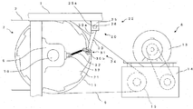
- FIG. 2 is an enlarged view of an essential part of the machine room of FIG. 1 and shows a state of normal operation.
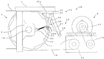
- FIG. 3 is an enlarged view of an essential part in the machine room of FIG. 1 and shows a state in which the operation of the emergency braking device is checked.
- FIG. 4 is an enlarged view of an essential part in the machine room of FIG. 1 and shows a broken drive chain.
- FIG. 5 is an enlarged view of the spring length adjuster in FIG.
- a main frame 1 is installed in a building (not shown), and a plurality of steps 3 endlessly connected by a step chain 2 are supported by the main frame 1.
- a pair of balustrades 4 are provided on both sides in the width direction of the steps 3.
- a sprocket device 7, a drive 8 for driving the sprocket device 7, and an emergency braking device 20 for applying a braking force to the sprocket device 7 in an emergency are provided in a machine room 5 at the upper end of the main frame 1 in the longitudinal direction. .
- the sprocket device 7 has a main shaft 10 extending in the width direction of the steps 3, a main shaft driving sprocket 11 fixed to the main shaft 10, and an upper step sprocket 12. As shown in FIG. 3, the main shaft 10 is rotatably supported by the main frame 1 via the housing 6. The main shaft 10, the main shaft drive sprocket 11, and the upper step sprocket 12 are integrally rotated.
- the drive unit 8 includes a motor 13, a speed reducer 14, and a drive unit sprocket 15.
- the drive sprocket 15 is driven by the motor 13 via the reduction gear 14.
- An endless drive chain 16 is wound around the drive machine sprocket 15 and the spindle drive sprocket 11.
- the drive chain 16 is tensioned between the drive sprocket 15 and the spindle drive sprocket 11.
- the driving force given by the motor 13 is transmitted to the steps 3 via the drive chain 16.
- a lower step sprocket 17 is provided which is supported and rotated by a rotation shaft which is disposed extending in the width direction of the step 3.
- the step chain 2 is wound around the upper step sprocket 12 and the lower step sprocket 17.
- the step chain 2 is driven as the upper step sprocket 12 rotates.
- the steps 3 are cyclically moved with the drive of the step chain 2.
- a brake system (not shown) brakes the drive sprocket 15 and the step 3 is braked through the drive chain 16 accordingly. Therefore, for example, when the drive chain 16 breaks, it is not possible to brake the step 3 using the brake device. In such an emergency, the emergency braking device 20 applies a braking force to the sprocket device 7 and the steps 3 are braked.
- the emergency braking device 20 includes a ratchet wheel 21 attached to the main shaft 10, a support device 22 attached to the main frame 1, a detection device 23 for detecting breakage of the drive chain 16, and engagement with the ratchet wheel 21. And a combining device 24.
- the ratchet wheel 21 is rotated integrally with the main shaft 10, the main shaft drive sprocket 11 and the upper step sprocket 12. Thereby, the ratchet wheel 21 is interlocked with the step 3, and when the rotation of the ratchet wheel 21 is braked, the step 3 is braked.
- the support device 22 has a bearing member 25 and a connecting shaft 26 as a shaft.
- a pair of bearing members 25 are attached to the main frame 1 at a position obliquely above the main shaft 10 at an interval.
- Each bearing member 25 has a hole 25a.
- the connecting shafts 26 are passed through the respective holes 25 a and can rotate in a state of being supported by the bearing members 25.
- the detection device 23 has a shoe lever 27 as a lever and a shoe 28 as a contact member.
- the shoe lever 27 is fixed at its root portion to the connecting shaft 26 by a bolt (not shown).
- the shoe lever 27 can be removed from the connecting shaft 26 by removing the bolt.
- the shoe lever 27 fixed to the connecting shaft 26 can rotate integrally with the connecting shaft 26.
- a shoe 28 is attached to the tip of the shoe lever 27.
- the shoe 28 is mounted on a drive chain 16 stretched between a drive sprocket 15 and a spindle drive sprocket 11 and is in contact with the drive chain 16.
- the shoe lever 27 is restricted from rotating toward the ratchet wheel 21.
- the drive chain 16 breaks, the shoes 28 do not contact the drive chain 16, the regulation of the pivoting of the shoe lever 27 is released, and the shoe lever 27 can pivot toward the ratchet wheel 21.
- the engagement device 24 has a ratchet pole 30 as an engagement claw, a spring length adjuster 31, a spring 32 and a fixing member 33.
- a base 30 a of the ratchet pole 30 is fixed to the connecting shaft 26.
- the shoe lever 27 and the ratchet pole 30 are connected by a connecting shaft 26.
- An engagement portion 30 b is provided on the distal end side of the ratchet pole 30.
- the ratchet pole 30 can rotate between a position where the engaging portion 30 b is separated from the ratchet wheel 21 and a position where the engaging portion 30 b is engaged with the ratchet wheel 21.
- a spring length adjuster 31 is provided on the distal end side of the ratchet pole 30.
- the fixing member 33 is attached to the housing 6.
- One of the springs 32 is attached to the fixing member 33 and the other is attached to the spring length adjuster 31.
- the spring length adjuster 31 has a stopper 35, a spring mounting bolt 36 and a nut 37.
- the stop member 35 is provided on the ratchet pole 30 so as to protrude in a direction perpendicular to the direction in which the ratchet pole 30 is pivoted.
- the stopper member 35 has a hole 35a penetrating in the direction in which the ratchet pole 30 is rotated.
- a spring 32 is attached to the bolt head 36 a of the spring attachment bolt 36.
- the threaded portion 36 b of the spring mounting bolt 36 is threaded through the hole 35 a of the locking member 35 and a nut 37 is mounted.
- the spring attachment bolt 36 is attached to the stop member 35.
- the force by which the spring 32 rotates the ratchet pole 30 increases as the length of the spring 32 increases and decreases as the length decreases.
- the magnitude of the force with which the shoe 28 presses against the drive chain 16 in a state in which the rotation of the ratchet pole 30 and the shoe lever 27 is restricted increases as the length of the spring 32 increases and decreases as the length decreases.
- the length of the spring 32 is adjusted to meet the ability to rotate the ratchet pole 30 to engage the ratchet wheel 21 and to ensure that the shoe 28 does not strike the drive chain 16 too much.
- the shoe lever 27 is removed from the connecting shaft 26, and the restriction on the rotation of the ratchet pole 30 is released. Then, the operation of checking whether the ratchet pole 30 is rotated and engaged with the ratchet wheel 21 is performed by the contraction force of the spring 32. After confirming the operation, the ratchet pole 30 is rotated in the direction away from the ratchet wheel 21, the shoe lever 27 is attached to the connecting shaft 26, the shoe 28 is placed on the drive chain 16, and the emergency braking device 20 is returned. As described above, only by detaching or attaching the shoe lever 27 from the connecting shaft 26, it is possible to easily check whether the ratchet pole 30 is rotated and engaged with the ratchet wheel 21.
- the ratchet pole 30 is rotated by two forces of the contracting force of the spring 32 and the force of the shoe lever 27 rotating by its own weight, so that the reliability as the emergency braking device 20 can be improved.
- the bearing member 25 supporting the connecting shaft 26 wears over time, and the force required to rotate the ratchet pole 30 increases, and the operation of the emergency braking device 20 becomes unstable.
- the force for turning the ratchet pole 30 toward the ratchet wheel 21 can be easily adjusted large.
- the ratchet pole 30 is rotated by the compression force of the spring 32, but the arrangement of the spring 32 is changed to rotate the ratchet pole 30 by the expansion force of the spring 32. It is good.
Landscapes
- Escalators And Moving Walkways (AREA)
Abstract
L'invention concerne un dispositif de freinage d'urgence pour un escalier roulant, lequel dispositif comporte : une roue à rochet qui est disposée sur un arbre principal et qui tourne d'un seul tenant avec l'arbre principal ; un crochet de mise en prise qui est amené à tourner entre une position dans laquelle le côté pointe est séparé de la roue à rochet et une position dans laquelle le côté pointe est en prise avec la roue à rochet ; un ressort qui est fixé au crochet de mise en prise et fait tourner le crochet de mise en prise pour l'amener à entrer en prise avec la roue à rochet ; un arbre auquel le crochet de mise en prise est fixé et qui tourne en coordination avec la rotation du crochet de mise en prise ; et une chaussure qui est fixée amovible à l'arbre et qui est disposée de façon à venir en butée contre une chaîne d'entraînement. Si la chaussure est fixée à l'arbre et vient en butée contre la chaîne d'entraînement, la rotation du crochet de mise en prise est régulée, séparant le crochet de mise en prise de la roue à rochet ; et si la chaussure est retirée de l'arbre, le crochet de mise en prise est mis en rotation pour venir en prise avec la roue à rochet.
Priority Applications (2)
| Application Number | Priority Date | Filing Date | Title |
|---|---|---|---|
| PCT/JP2017/025496 WO2019012641A1 (fr) | 2017-07-13 | 2017-07-13 | Dispositif de freinage d'urgence pour escalier roulant |
| JP2018537550A JPWO2019012641A1 (ja) | 2017-07-13 | 2017-07-13 | 乗客コンベアの非常制動装置 |
Applications Claiming Priority (1)
| Application Number | Priority Date | Filing Date | Title |
|---|---|---|---|
| PCT/JP2017/025496 WO2019012641A1 (fr) | 2017-07-13 | 2017-07-13 | Dispositif de freinage d'urgence pour escalier roulant |
Publications (1)
| Publication Number | Publication Date |
|---|---|
| WO2019012641A1 true WO2019012641A1 (fr) | 2019-01-17 |
Family
ID=65001898
Family Applications (1)
| Application Number | Title | Priority Date | Filing Date |
|---|---|---|---|
| PCT/JP2017/025496 Ceased WO2019012641A1 (fr) | 2017-07-13 | 2017-07-13 | Dispositif de freinage d'urgence pour escalier roulant |
Country Status (2)
| Country | Link |
|---|---|
| JP (1) | JPWO2019012641A1 (fr) |
| WO (1) | WO2019012641A1 (fr) |
Cited By (2)
| Publication number | Priority date | Publication date | Assignee | Title |
|---|---|---|---|---|
| JP2022176544A (ja) * | 2021-05-17 | 2022-11-30 | 東芝エレベータ株式会社 | 乗客コンベア |
| JP2024084381A (ja) * | 2022-12-13 | 2024-06-25 | 東芝エレベータ株式会社 | 乗客コンベアに用いる治具とその治具を用いた弛み量測定装置の取り付け方法 |
Citations (5)
| Publication number | Priority date | Publication date | Assignee | Title |
|---|---|---|---|---|
| JPS50153694U (fr) * | 1974-06-06 | 1975-12-20 | ||
| JPS5114685B1 (fr) * | 1973-07-09 | 1976-05-11 | ||
| JPH0172579U (fr) * | 1987-11-05 | 1989-05-16 | ||
| JP2008024480A (ja) * | 2006-07-24 | 2008-02-07 | Mitsubishi Electric Corp | マンコンベアの非常制動装置 |
| CN104649117A (zh) * | 2013-11-25 | 2015-05-27 | 天津市津阳金属制品有限公司 | 一种自动扶梯制动机构 |
Family Cites Families (3)
| Publication number | Priority date | Publication date | Assignee | Title |
|---|---|---|---|---|
| JPS5114685A (en) * | 1974-07-26 | 1976-02-05 | Tokyo Shibaura Electric Co | Esukareetano seidoanzensochi |
| JPS5774366U (fr) * | 1980-10-23 | 1982-05-08 | ||
| JP4824537B2 (ja) * | 2006-12-12 | 2011-11-30 | 三菱電機ビルテクノサービス株式会社 | エスカレータ用ドライブチェーン調整装置 |
-
2017
- 2017-07-13 JP JP2018537550A patent/JPWO2019012641A1/ja active Pending
- 2017-07-13 WO PCT/JP2017/025496 patent/WO2019012641A1/fr not_active Ceased
Patent Citations (5)
| Publication number | Priority date | Publication date | Assignee | Title |
|---|---|---|---|---|
| JPS5114685B1 (fr) * | 1973-07-09 | 1976-05-11 | ||
| JPS50153694U (fr) * | 1974-06-06 | 1975-12-20 | ||
| JPH0172579U (fr) * | 1987-11-05 | 1989-05-16 | ||
| JP2008024480A (ja) * | 2006-07-24 | 2008-02-07 | Mitsubishi Electric Corp | マンコンベアの非常制動装置 |
| CN104649117A (zh) * | 2013-11-25 | 2015-05-27 | 天津市津阳金属制品有限公司 | 一种自动扶梯制动机构 |
Cited By (2)
| Publication number | Priority date | Publication date | Assignee | Title |
|---|---|---|---|---|
| JP2022176544A (ja) * | 2021-05-17 | 2022-11-30 | 東芝エレベータ株式会社 | 乗客コンベア |
| JP2024084381A (ja) * | 2022-12-13 | 2024-06-25 | 東芝エレベータ株式会社 | 乗客コンベアに用いる治具とその治具を用いた弛み量測定装置の取り付け方法 |
Also Published As
| Publication number | Publication date |
|---|---|
| JPWO2019012641A1 (ja) | 2019-07-11 |
Similar Documents
| Publication | Publication Date | Title |
|---|---|---|
| CN1051507C (zh) | 钢丝松紧调节器 | |
| CN1280142C (zh) | 电动制动驱动总成及驱动器 | |
| CN105253799B (zh) | 用于绞车的松弛绳线检测系统 | |
| JP5657138B2 (ja) | エレベータの非常止め装置、及びエレベータの非常止め装置の取付方法 | |
| JP5051650B2 (ja) | 乗客コンベア用非常制動装置 | |
| JPH08119555A (ja) | エレベータ用調速機 | |
| WO2013035175A1 (fr) | Dispositif d'arrêt d'urgence d'ascenseur, et procédé pour attacher un dispositif d'arrêt d'urgence d'ascenseur | |
| WO2019012641A1 (fr) | Dispositif de freinage d'urgence pour escalier roulant | |
| CN103204424A (zh) | 乘客输送机的辅助制动装置以及乘客输送机 | |
| JP6018906B2 (ja) | エレベータにおける巻上機用制動器 | |
| JP6797080B2 (ja) | 乗客コンベヤ用安全装置、及び乗客コンベヤ用安全装置の点検方法 | |
| JP6253777B2 (ja) | 乗客コンベヤの安全装置 | |
| WO2018011960A1 (fr) | Dispositif de sécurité pour tapis roulant | |
| JP6335766B2 (ja) | 乗客コンベヤのラチェットホイール用歯装置 | |
| JP2607607B2 (ja) | 送電線の走行装置 | |
| US11780715B2 (en) | Hoist brake | |
| JP5808157B2 (ja) | 索条牽引式輸送設備の非常制動装置 | |
| JP6832791B2 (ja) | エスカレーター非常制動装置 | |
| CN205590212U (zh) | 带自锁装置的鼓式制动器单组手动松闸扳手 | |
| JP7575917B2 (ja) | 乗客コンベアの制動機及びその動作確認治具 | |
| JP7227120B2 (ja) | エレベーター調速機 | |
| JP5619293B2 (ja) | エレベータの非常止め装置、及びエレベータの非常止め装置の取付方法 | |
| CN113023610B (zh) | 电梯的双重化制动装置以及电梯的制动装置的双重化更新方法 | |
| JP2024075258A (ja) | マンコンベヤのブレーキの制動トルク調整装置 | |
| JP2812594B2 (ja) | 乗客コンベアのチェーン張力調整装置 |
Legal Events
| Date | Code | Title | Description |
|---|---|---|---|
| ENP | Entry into the national phase |
Ref document number: 2018537550 Country of ref document: JP Kind code of ref document: A |
|
| 121 | Ep: the epo has been informed by wipo that ep was designated in this application |
Ref document number: 17917660 Country of ref document: EP Kind code of ref document: A1 |
|
| NENP | Non-entry into the national phase |
Ref country code: DE |
|
| 122 | Ep: pct application non-entry in european phase |
Ref document number: 17917660 Country of ref document: EP Kind code of ref document: A1 |