WO2019012736A1 - Système de détection de glissement - Google Patents
Système de détection de glissement Download PDFInfo
- Publication number
- WO2019012736A1 WO2019012736A1 PCT/JP2018/009340 JP2018009340W WO2019012736A1 WO 2019012736 A1 WO2019012736 A1 WO 2019012736A1 JP 2018009340 W JP2018009340 W JP 2018009340W WO 2019012736 A1 WO2019012736 A1 WO 2019012736A1
- Authority
- WO
- WIPO (PCT)
- Prior art keywords
- slip
- protrusion
- slip detection
- detection sensor
- detection system
- Prior art date
- Legal status (The legal status is an assumption and is not a legal conclusion. Google has not performed a legal analysis and makes no representation as to the accuracy of the status listed.)
- Ceased
Links
Images



Classifications
-
- B—PERFORMING OPERATIONS; TRANSPORTING
- B25—HAND TOOLS; PORTABLE POWER-DRIVEN TOOLS; MANIPULATORS
- B25J—MANIPULATORS; CHAMBERS PROVIDED WITH MANIPULATION DEVICES
- B25J13/00—Controls for manipulators
- B25J13/08—Controls for manipulators by means of sensing devices, e.g. viewing or touching devices
-
- G—PHYSICS
- G01—MEASURING; TESTING
- G01L—MEASURING FORCE, STRESS, TORQUE, WORK, MECHANICAL POWER, MECHANICAL EFFICIENCY, OR FLUID PRESSURE
- G01L1/00—Measuring force or stress, in general
- G01L1/18—Measuring force or stress, in general using properties of piezo-resistive materials, i.e. materials of which the ohmic resistance varies according to changes in magnitude or direction of force applied to the material
-
- G—PHYSICS
- G01—MEASURING; TESTING
- G01L—MEASURING FORCE, STRESS, TORQUE, WORK, MECHANICAL POWER, MECHANICAL EFFICIENCY, OR FLUID PRESSURE
- G01L5/00—Apparatus for, or methods of, measuring force, work, mechanical power, or torque, specially adapted for specific purposes
-
- G—PHYSICS
- G01—MEASURING; TESTING
- G01L—MEASURING FORCE, STRESS, TORQUE, WORK, MECHANICAL POWER, MECHANICAL EFFICIENCY, OR FLUID PRESSURE
- G01L5/00—Apparatus for, or methods of, measuring force, work, mechanical power, or torque, specially adapted for specific purposes
- G01L5/22—Apparatus for, or methods of, measuring force, work, mechanical power, or torque, specially adapted for specific purposes for measuring the force applied to control members, e.g. control members of vehicles, triggers
-
- G—PHYSICS
- G01—MEASURING; TESTING
- G01N—INVESTIGATING OR ANALYSING MATERIALS BY DETERMINING THEIR CHEMICAL OR PHYSICAL PROPERTIES
- G01N19/00—Investigating materials by mechanical methods
- G01N19/02—Measuring coefficient of friction between materials
Definitions
- the present invention relates to a slip detection system.
- This application claims the priority based on Japanese Patent Application No. 2017-135868 filed on Jul. 12, 2017 in Japan, the entire contents of the basic Japanese application are incorporated in the present application, and the contents of the present application. It is
- a gripping mechanism (also referred to as a robot hand) is used by automated robots in production lines and inspection lines, and autonomous mobile robots to carry gripping objects.
- the grasping object of the grasping mechanism is various grasping objects which differ in hardness, weight, shape, size, etc.
- a sensing system for detecting the grasping object in order to grasp it without slipping or breaking it Is required.
- Patent Document 1 a plurality of sensor units are arranged in a matrix, and the barycentric position of an object is calculated by a plurality of strain sensors incorporated in each sensor unit, whereby the appropriate force is obtained by Techniques for adjusting grip are presented.
- Patent Document 2 a plurality of contact sensors and an optical slip sensor module are disposed in the hand unit, and the position of the operation object is detected using the contact sensor, and the position of the operation object and the optical slip sensor Techniques have been presented to control slip detection points detected by the modules to coincide.
- An object of the present invention is to calculate a gripping force close to the minimum at which an object does not slip with high accuracy and a simple configuration.
- the present invention has the following features, for example.
- a deformation detection sensor comprising a plurality of projections, a deformation detection sensor, and a slip detection means, wherein the deformation detection sensor is disposed on at least one of the plurality of projections, and the deformation detection sensor is not disposed.
- the slip detection means causes a slip between the object on which the deformation detection sensor is placed and the object depending on the value of the deformation detection sensor. Calculate one grip force.
- FIG. 1 is a view showing an example of the configuration of a gripping mechanism according to a first embodiment of the present invention.
- the gripping mechanism includes a hand 101 for performing gripping, and an arm 102 for causing the hand 101 to approach the object 104.
- the hand 101 includes a drive unit 105 that enables the opening and closing operation of the hand, a grip unit 100 that grips an object, and a sensor unit 103 that is disposed in the grip unit 100 and that detects slippage of the object.
- the arm 102 is provided with an arm drive unit 106 which enables three-dimensional movement of the arm 102.
- the drive unit 105 and the arm drive unit 106 are controlled by the controller 108 via the amplifier 107.
- a CPU 109, a memory 110, a slip detection means 112, and a margin calculation means 113 are mounted, and in the memory 110, a database 111 is provided.
- FIG. 1 is a view schematically showing a gripping mechanism that grips the target object 104, and a slip detection system to which the present invention can be applied is not limited to such a gripping mechanism.
- the hand 101 may have a plurality of fingers like human hands, and the sensor unit 103 may be provided on each finger. In that case, if the small object 104 is gripped by the two fingers of the hand, the object 104 is grasped by the two fingers of the hand 101 if the object is large 104, etc. You may Furthermore, in the case of a large object 104, gripping may be performed using a plurality of gripping mechanisms.
- the sensor unit 103 may be provided on the finger necessary to detect slippage.
- the simplest configuration is the hand 101 as shown in FIG. 1, and the sensor unit 103 may be provided on at least one of the gripping surfaces.
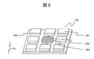
- FIG. 2 is a diagram showing the configuration of the sensor unit 103 according to the present embodiment.
- FIG. 2 is a diagram showing the sensor unit 103 such that the contact surface with the object 104 is on the top.
- the contact surface is a surface when the object and the sensor unit 103 contact, and more specifically, the holding projection 201 and the slip detection projection 202 installed in the sensor unit 103, and the object 104 It is the surface when it contacts. In the case of the hand 101, it is also referred to as a gripping surface.
- the sensor unit 103 includes a fixed base 203 attached to the surface where the hand contacts the object, a plurality of protrusions 201 to 202 arranged in a matrix (in the vertical and horizontal directions) on the fixed base 203, and a plurality of protrusions 201 to A deformation detection sensor 204 that detects deformation of 202 is provided.
- the plurality of protrusions 201 to 202 form a contact surface with the object 104.
- At least one protrusion is different from the other protrusions and can slide faster than the other protrusions when being sheared.
- a plurality of deformation detection sensors 204 are arranged, it has a structure capable of detecting the slip of the object.
- a slippery protrusion with the object 104 is referred to as a slip detection protrusion 202
- the other protrusion, that is, a protrusion less slippery than the slip detection protrusion 202 is referred to as a grip protrusion 201.
- the deformation detection sensor 204 needs to be disposed at least on the slip detection projection 202. However, by disposing the deformation detection sensor 204 also on the holding projection 201, the holding force and the shearing force can be calculated with higher accuracy.
- each projection is shown as a substantially rectangular shape, but the present invention is not limited to this, as long as it is a member that protrudes from the fixed base and is deformed by receiving a gripping force or a shearing force Example: circular, triangular) is not limited.
- the projections are arranged in 3 ⁇ 3 is shown in FIG. 2, it is also possible to arrange fewer (at least 2 ⁇ 2) or more projections.
- the protrusions may be arranged by other arrangement such as concentric or spiral. It is desirable that each projection be disposed at a predetermined gap, and be configured not to be affected by the deformation of the other projections.
- the sensor unit 103 is not limited to being on a plane, and may be disposed on a curved surface. Further, the grip portion 100 may be used as the fixed base 203.
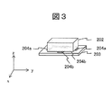
- FIG. 3 is a view showing the configuration of the periphery of the slip detection protrusion 202 shown in FIG.
- the slip detection projection 202 receives a shear force along the grip surface from the object to be deformed, and the deformation detection sensor 204 receives the deformation to be strained, thereby detecting the shear force.
- four deformation detection sensors (two 204a and two 204b) are arranged horizontally on each side of the substantially rectangular projection.
- a sensor that detects a shear force in the Y direction is a deformation detection sensor 204a
- a sensor that detects a shear force in the X direction is a deformation detection sensor 204b.
- the gripping force (Z direction) can be calculated from all the sensors.
- the deformation detection sensors 204a and 204b are not limited to the arrangement of FIG. 3, and may be an arrangement capable of detecting a gripping force and a shearing force.
- strain gauges can be used as the deformation detection sensors 204a and 204b.
- various other configurations can be adopted.
- MEMS Micro-Electro Mechanical Systems
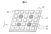
- FIG. 4 shows an example of the sensor unit 103 in which the protrusions are arranged in 5 ⁇ 5.
- a plurality of slip detection projections 202 are provided as illustrated in FIG. 4, one slip detection projection 202 is generated because the surface of the target object 104 has unevenness when gripping the target object 104. Slip detection is possible from the average of the signals of the other slip detection projections 202 in contact with the object 104 without contact with them.
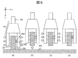
- FIG. 5 shows an example of a process for slip detection.
- FIG. 6 is a flowchart of this process.
- the position, shape, hardness, and weight of the object 104 are estimated by an optical sensor (not shown) to estimate an initial gripping force.
- the arm 102 moves the hand 101 to the vicinity of the target object 104, and the hand 101 grips the target object 104 with the estimated gripping force (FIG. 5a, 601 to 603).
- the arm 102 lifts the object 104 from the ground 507 by the movement of the Y axis (FIG. 5b, 604 to 605).
- the gripping force of the hand 101 is gradually decreased (FIG. 5c, 606), and when the slip of the slip detection protrusion 202 is detected by the deformation detection sensor 204 (FIG. 5d, 607) Stop reducing power.
- the gripping force at this time is a gripping force immediately before the gripping projection 201 slips, and is a gripping force close to the minimum necessary for gripping the object 104.
- the object can be gripped with a gripping force close to the minimum, and the gripped object can be gripped without slipping or breaking.
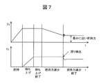
- FIG. 7 shows an example of the signal of the slip detection projection 202 when the process shown in FIGS. 5 and 6 is performed.
- the force Fz in the Z direction gradually increases until the movement of the hand 101 is stopped after the slip detection projection 202 contacts the object 104.
- the force Fy in the Y direction increases until the object 104 is completely lifted.
- Fz gradually decreases as the distance between the hands gradually increases.
- the frictional force between the slip detection projection 202 and the object 104 also gradually decreases, and when the frictional force becomes lower than the shear force, Fy decreases rapidly.
- the timing at which the Fy signal changes is when the slip detection projection 202 slips. Since the hand operation is stopped when a sharp drop in Fy is detected, the signals of Fz and Fy become constant thereafter.
- the Fz signal at this time corresponds to a gripping force close to the minimum for grasping the object 104.
- the gripping force close to the minimum can be detected more accurately.
- the surface friction lower than the grip protrusion 201 that is, the slip detection protrusion 202 having a low coefficient of friction, or shear rigidity higher than the grip protrusion 201 It may be a slip detection projection 202 having
- the first method is to change the surface finish (roughness) of the protrusions while using the same shape and material.
- a smooth surface (lower coefficient of friction) slip detection protrusion 202 can slide faster than the gripping protrusion 201 when subjected to the same amount of shear stress.
- the second method is to use a material with a lower coefficient of friction for the slip detection protrusions 202.
- This method has the same effect as the first method, but since the coefficient of friction depends on the interaction between the projection and the object, it should be taken into account that the coefficient differs depending on the object to be handled . Therefore, the friction coefficient of the slip detection projection 202 may be smaller in one target object than in the grip projection 201, and may be larger in another target object.
- Examples of materials that can be used for producing the protrusion include silicone for the slip detection protrusion 202 and Teflon (registered trademark) for the gripping protrusion 201.
- the first method is to make the length L of the entire protrusion from the fixed base the same, and to make the contact area A of the slip detection protrusion 202 with the object larger.
- the slip detection projection 202 having higher shear rigidity is considered, considering that all the projections are deformed in the same manner (.DELTA.Y displacement of the coordinate axis Y shown in FIG. 5 is the same). Since the friction force is more quickly overcome than the gripping projection 201 by generating a larger shear force, it slides faster. Therefore, it is desirable that the slip detection projection 202 be shaped such that the contact area A with the object becomes large.
- the second method is to use a more rigid material for the slip detection projection 202.
- Materials that are more rigid generate higher shear than other materials and slide faster than other materials when subjected to the same amount of shear stress. As mentioned above, different materials have different coefficients of friction, so they should be taken into consideration when selecting materials for both types of protrusions. Examples of materials that can be used for producing the protrusions include silicone with low polymerization agent for the slip detection projections 202 and silicone with high polymerization agent for the gripping projections 201.
- FIG. 8 is a flowchart in the case where the ratio of the rigidity of the slip detection protrusion 202 and the grip protrusion 201 is set.
- 801 to 808 are equal to 601 to 608 in FIG. 6, and 809 and 810 are processes of the tolerance calculation means 113.
- a method of calculating the degree of freedom will be described.
- the slip of the slip detection projection 202 is detected, and the gripping force close to the minimum is detected. Then, using the data on the rigidity of each projection in the database 111, based on the gripping force close to the minimum calculated by the slip detecting means 112, until the object slips from the gripping projection 201, that is, the sliding of the contact surface Calculate the margin until occurrence (809 to 810). Furthermore, although not shown, a minimum gripping force which is a gripping force just before the occurrence of the slip of the contact surface is calculated based on the gripping force close to the minimum and the calculated latitude. Then, the calculated tolerance or minimum gripping force is stored in the database 111 of the controller 108 (811).
- the tolerance calculation means 113 calculates the tolerance to slip of the contact surface.
- the slip detection system of the present invention it is possible to obtain a gripping force close to the minimum that the object does not slip with high accuracy, simplicity and low cost.
- the minimum gripping force can be calculated and fed back to the gripping mechanism or to a device that requires slip detection.
- the locations of the slip detection means 112 and the tolerance calculation means 113 are not limited to this, and the CPU 109 may play the roles of the slip detection means 112 and the tolerance calculation means 113.
- the slip detection system of the present invention does not necessarily have to be used by the gripping mechanism and the robotic hand, but can be used with any device that requires slip detection.
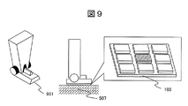
- a method of using the slip detection system with the robot leg 901 of a walking robot (not shown) is shown.
- the robot leg 901 detects slippage between the ground 507 and the robot leg rather than the object. If sliding can not be detected properly, the walking robot may lose its balance and fall. Since recent walking robots need to walk on various ground conditions, it is important to detect the slip of the robot legs 901.
- the sensor unit 103 is disposed at a portion of the robot leg 901 that is in contact with the ground as shown in FIG.
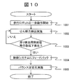
- FIG. 10 shows the slip detection process in robot leg 901.
- shear force detection is started between the robot leg 901 and the ground 507 (1001 to 1002).
- shear force detection is performed until a sharp drop occurs in the shear force signal of the slip detection projection 202 (1002 to 1003), and if the shear force signal suddenly drops, the information is fed back to the control system of the walking robot (1003 to 1004).
- the control system uses the information on the slip to take balance stabilization measures so as not to lose the balance of the traveling robot (1005).
- a balance stabilization measure is a method of detecting the direction in which the slip detection projection 202 slips, and moving another robot leg 901 in the opposite direction.
- the robot leg 901 shown in FIG. 9 not only the configuration of the robot leg 901 shown in FIG. 9 but also other robot legs can be used. Further, without being limited to the shape and size of the ground 507 shown in FIG. 9, any shape and size may be used as long as slippage can be detected by the method described in the first embodiment. However, the smaller the entire protrusion of the sensor unit 103, the smaller the measurement error regarding the shape of the robot. Therefore, the sensor unit 103 having a smaller protrusion is preferable.
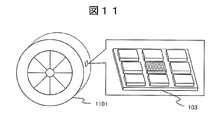
- FIGS. A third embodiment of the present invention will be described with reference to FIGS. This example shows how to use a slip detection system on a tire.
- ABS antilock brake system
- ABS is often used as a vehicle safety mechanism, but it relies on the actual occurrence of wheel slippage and experimentally defined thresholds.
- the system may malfunction because the system is not equipped with a sensor that actually detects tire slip. Therefore, the present invention is useful for tire slip detection.
- the slip of the tire 1101 can be detected, and this information can be fed back to the vehicle brake control system. Then, the ABS can be used instead of the used threshold to prevent the malfunction of the ABS.
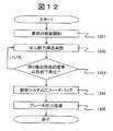
- the slip detection process of the tire 1101 will be described with reference to FIG. After the movement of the vehicle is started, detection of the shear force of the tire 1101 is started (1201 to 1202). Thereafter, shear force detection is performed until the shear force signal of the slip detection projection 202 is sharply dropped (1202 to 1203), and if the shear force signal is sharply dropped, the information is fed back to the vehicle brake control system ( 1203-1204). The control system then uses the information on the slip to reduce the braking force of the tire 1101 that has been slip detected such that the tire 1101 is not locked (1205).
- the slip detection system is used for a vehicle tire, but is not limited to the vehicle.
- Slip detection systems are used in all systems where it is necessary to prevent wheel slip.
- wear on the protrusions is also reduced, so that the ability to detect slip can be maintained.
- Reference Signs List 100 grip unit 101 hand 102 arm 103 sensor unit 104 object 105 drive unit 106 arm drive unit 107 amplifier 108 controller 109 CPU 110 memory 111 database 112 slip detection means 113 tolerance calculation means 201 grip projection 202 slip detection projection 203 fixed base 204 deformation detection sensor 204a Y direction deformation detection sensor 204b X direction deformation detection sensor 507 ground 601 to 609 Near grip force detection sequence 801 to 809 Sequence for detection and margin calculation of grip force close to minimum 901 Robot leg 1001 to 1004 Robot leg slip detection sequence 1101 Tire 1201 to 1205 Tire slip detection sequence
Landscapes
- Engineering & Computer Science (AREA)
- General Physics & Mathematics (AREA)
- Physics & Mathematics (AREA)
- General Health & Medical Sciences (AREA)
- Immunology (AREA)
- Chemical & Material Sciences (AREA)
- Analytical Chemistry (AREA)
- Biochemistry (AREA)
- Health & Medical Sciences (AREA)
- Automation & Control Theory (AREA)
- Life Sciences & Earth Sciences (AREA)
- Pathology (AREA)
- Human Computer Interaction (AREA)
- Robotics (AREA)
- Mechanical Engineering (AREA)
- Manipulator (AREA)
- Force Measurement Appropriate To Specific Purposes (AREA)
Abstract
La présente invention permet le calcul approximatif de la force de préhension minimale nécessaire pour empêcher le glissement d'un objet, grâce à une grande précision et une configuration simple. Le système de détection de glissement de l'invention comprend une pluralité de saillies, un capteur de détection de déformation (204) et un moyen de détection de glissement (112). Le capteur de détection de déformation (204) est disposé dans au moins l'une desdites saillies. Un glissement entre l'objet et une saillie (202) du capteur de détection de déformation (204) se produit plus facilement par comparaison avec une saillie (201) non fournie avec le capteur de détection de déformation (204). Le moyen de détection de glissement (112) utilise une valeur provenant du capteur de détection de déformation (204) afin de calculer une première force de préhension correspondant au moment où un glissement se produit entre l'objet et la saillie (202), le capteur de détection de déformation (204) étant disposé sur cette dernière.
Applications Claiming Priority (2)
| Application Number | Priority Date | Filing Date | Title |
|---|---|---|---|
| JP2017135868A JP6827381B2 (ja) | 2017-07-12 | 2017-07-12 | 滑り検出システム |
| JP2017-135868 | 2017-07-12 |
Publications (1)
| Publication Number | Publication Date |
|---|---|
| WO2019012736A1 true WO2019012736A1 (fr) | 2019-01-17 |
Family
ID=65002495
Family Applications (1)
| Application Number | Title | Priority Date | Filing Date |
|---|---|---|---|
| PCT/JP2018/009340 Ceased WO2019012736A1 (fr) | 2017-07-12 | 2018-03-09 | Système de détection de glissement |
Country Status (2)
| Country | Link |
|---|---|
| JP (1) | JP6827381B2 (fr) |
| WO (1) | WO2019012736A1 (fr) |
Cited By (3)
| Publication number | Priority date | Publication date | Assignee | Title |
|---|---|---|---|---|
| WO2019244710A1 (fr) * | 2018-06-22 | 2019-12-26 | ソニー株式会社 | Dispositif de détection de glissement |
| CN112692854A (zh) * | 2020-12-11 | 2021-04-23 | 合肥工业大学 | 一种柔性机械手 |
| CN113950396A (zh) * | 2019-06-05 | 2022-01-18 | 索尼集团公司 | 控制装置、控制方法及程序 |
Families Citing this family (9)
| Publication number | Priority date | Publication date | Assignee | Title |
|---|---|---|---|---|
| CN114206557B (zh) * | 2019-07-23 | 2024-12-03 | 索尼集团公司 | 控制装置、控制方法和控制程序 |
| US11607816B2 (en) | 2019-10-25 | 2023-03-21 | Dexterity, Inc. | Detecting robot grasp of very thin object or feature |
| US11772262B2 (en) | 2019-10-25 | 2023-10-03 | Dexterity, Inc. | Detecting slippage from robotic grasp |
| JP7480600B2 (ja) * | 2020-06-11 | 2024-05-10 | セイコーエプソン株式会社 | 目標力上限値設定方法およびロボットシステム |
| KR102364156B1 (ko) * | 2020-07-17 | 2022-02-17 | 부산대학교 산학협력단 | 다수개의 기압 센서들을 갖는 로봇 핸드 및 그의 슬립 감지 방법 |
| CN112060123A (zh) * | 2020-09-07 | 2020-12-11 | 苏州国岭技研智能科技有限公司 | 一种平夹触觉机械爪装置及使用方法 |
| CN116507460A (zh) | 2020-11-10 | 2023-07-28 | 索尼集团公司 | 信息处理装置、信息处理方法和程序 |
| AU2021413988A1 (en) * | 2020-12-29 | 2023-07-06 | Cascade Corporation | Pivoting load-bearing assembly with force sensor |
| CN117255731A (zh) * | 2021-05-11 | 2023-12-19 | 索尼集团公司 | 机器人系统、控制装置和控制方法 |
Citations (3)
| Publication number | Priority date | Publication date | Assignee | Title |
|---|---|---|---|---|
| JPS63134929A (ja) * | 1986-11-07 | 1988-06-07 | クリスタル インスツルメンテ アクチエンゲゼルシャフト | 多要素動力計 |
| JP2008281403A (ja) * | 2007-05-09 | 2008-11-20 | Univ Of Tokyo | 剪断力検出装置及び物体把持システム |
| JP2013096884A (ja) * | 2011-11-02 | 2013-05-20 | Seiko Epson Corp | 検出装置、電子機器、及びロボット |
Family Cites Families (5)
| Publication number | Priority date | Publication date | Assignee | Title |
|---|---|---|---|---|
| JP2009255191A (ja) * | 2008-04-14 | 2009-11-05 | Canon Inc | ロボットマニピュレータ |
| JP5253293B2 (ja) * | 2009-05-20 | 2013-07-31 | 株式会社豊田自動織機 | 摩擦係数同定方法、把持制御方法、この把持制御方法を行うロボットハンド及びプログラム |
| JP5498227B2 (ja) * | 2010-03-30 | 2014-05-21 | 本田技研工業株式会社 | 滑り覚検知装置及び滑り覚検知方法 |
| JP2015009326A (ja) * | 2013-06-28 | 2015-01-19 | キヤノン株式会社 | ロボットハンド及びロボットハンドでワークを把持する把持方法 |
| JP6682074B2 (ja) * | 2015-11-12 | 2020-04-15 | アダマンド並木精密宝石株式会社 | 把持装置 |
-
2017
- 2017-07-12 JP JP2017135868A patent/JP6827381B2/ja not_active Expired - Fee Related
-
2018
- 2018-03-09 WO PCT/JP2018/009340 patent/WO2019012736A1/fr not_active Ceased
Patent Citations (3)
| Publication number | Priority date | Publication date | Assignee | Title |
|---|---|---|---|---|
| JPS63134929A (ja) * | 1986-11-07 | 1988-06-07 | クリスタル インスツルメンテ アクチエンゲゼルシャフト | 多要素動力計 |
| JP2008281403A (ja) * | 2007-05-09 | 2008-11-20 | Univ Of Tokyo | 剪断力検出装置及び物体把持システム |
| JP2013096884A (ja) * | 2011-11-02 | 2013-05-20 | Seiko Epson Corp | 検出装置、電子機器、及びロボット |
Cited By (11)
| Publication number | Priority date | Publication date | Assignee | Title |
|---|---|---|---|---|
| WO2019244710A1 (fr) * | 2018-06-22 | 2019-12-26 | ソニー株式会社 | Dispositif de détection de glissement |
| CN112334746A (zh) * | 2018-06-22 | 2021-02-05 | 索尼公司 | 滑动检测装置 |
| EP3812729A4 (fr) * | 2018-06-22 | 2021-08-25 | Sony Group Corporation | Dispositif de détection de glissement |
| US20210260776A1 (en) * | 2018-06-22 | 2021-08-26 | Sony Corporation | Slip detecting device |
| CN112334746B (zh) * | 2018-06-22 | 2022-08-26 | 索尼公司 | 滑动检测装置 |
| US11981026B2 (en) | 2018-06-22 | 2024-05-14 | Sony Corporation | Slip detecting device |
| CN113950396A (zh) * | 2019-06-05 | 2022-01-18 | 索尼集团公司 | 控制装置、控制方法及程序 |
| CN113950396B (zh) * | 2019-06-05 | 2024-04-02 | 索尼集团公司 | 控制装置、控制方法及程序 |
| US12226908B2 (en) | 2019-06-05 | 2025-02-18 | Sony Group Corporation | Control device, control method, and program |
| CN112692854A (zh) * | 2020-12-11 | 2021-04-23 | 合肥工业大学 | 一种柔性机械手 |
| CN112692854B (zh) * | 2020-12-11 | 2022-04-01 | 合肥工业大学 | 一种柔性机械手 |
Also Published As
| Publication number | Publication date |
|---|---|
| JP6827381B2 (ja) | 2021-02-10 |
| JP2019018253A (ja) | 2019-02-07 |
Similar Documents
| Publication | Publication Date | Title |
|---|---|---|
| WO2019012736A1 (fr) | Système de détection de glissement | |
| US4605354A (en) | Slip sensitive robot gripper system | |
| CN108349090B (zh) | 用于在铰接臂中提供接触检测的系统和方法 | |
| JP5187552B2 (ja) | 制御装置および方法、プログラム並びに記録媒体 | |
| US7984658B2 (en) | Detecting device | |
| JP2020069640A5 (fr) | ||
| US20170129523A1 (en) | Handcart | |
| CN110480628B (zh) | 机器人、控制装置以及机器人控制方法 | |
| CN110549330A (zh) | 机器人、控制装置以及机器人的控制方法 | |
| KR20150089959A (ko) | 웨이퍼 핸들링 견인 제어 시스템 | |
| US8949044B2 (en) | Control device, control method and program | |
| KR20130136477A (ko) | 로봇 시스템의 퍼리퍼럴 구성요소를 제어하기 위한 방법 및 장치 | |
| KR102586779B1 (ko) | 제어 장치, 제어 방법, 및 프로그램 | |
| JP2013103306A (ja) | 把持方法 | |
| CN114750768A (zh) | 车辆状态估计装置、车辆状态估计方法及非暂时性计算机可读存储介质 | |
| KR102695661B1 (ko) | 제어 장치, 제어 방법 및 프로그램 | |
| US20250162177A1 (en) | Gripping control method of robot hand | |
| CN115784080A (zh) | 一种举升组件、无人搬运车及防倾覆控制方法 | |
| EP3546135A1 (fr) | Système de robot de collaboration | |
| Koda et al. | Grasping force control in master-slave system with partial slip sensor | |
| Sugaiwa et al. | A methodology for setting grasping force for picking up an object with unknown weight, friction, and stiffness | |
| JP5167077B2 (ja) | 移動体、及びその制御方法 | |
| WO2020250789A1 (fr) | Dispositif d'apprentissage direct et procédé d'apprentissage direct | |
| US20250196334A1 (en) | Control apparatus, robot control system, and method for controlling robot | |
| EP3546134A1 (fr) | Système de robot de collaboration |
Legal Events
| Date | Code | Title | Description |
|---|---|---|---|
| 121 | Ep: the epo has been informed by wipo that ep was designated in this application |
Ref document number: 18831761 Country of ref document: EP Kind code of ref document: A1 |
|
| NENP | Non-entry into the national phase |
Ref country code: DE |
|
| 122 | Ep: pct application non-entry in european phase |
Ref document number: 18831761 Country of ref document: EP Kind code of ref document: A1 |