WO2019012921A1 - 車両における制動支援装置および制動支援制御方法 - Google Patents
車両における制動支援装置および制動支援制御方法 Download PDFInfo
- Publication number
- WO2019012921A1 WO2019012921A1 PCT/JP2018/023128 JP2018023128W WO2019012921A1 WO 2019012921 A1 WO2019012921 A1 WO 2019012921A1 JP 2018023128 W JP2018023128 W JP 2018023128W WO 2019012921 A1 WO2019012921 A1 WO 2019012921A1
- Authority
- WO
- WIPO (PCT)
- Prior art keywords
- braking
- vehicle
- timing
- support
- assistance
- Prior art date
- Legal status (The legal status is an assumption and is not a legal conclusion. Google has not performed a legal analysis and makes no representation as to the accuracy of the status listed.)
- Ceased
Links
Images


Classifications
-
- B—PERFORMING OPERATIONS; TRANSPORTING
- B60—VEHICLES IN GENERAL
- B60T—VEHICLE BRAKE CONTROL SYSTEMS OR PARTS THEREOF; BRAKE CONTROL SYSTEMS OR PARTS THEREOF, IN GENERAL; ARRANGEMENT OF BRAKING ELEMENTS ON VEHICLES IN GENERAL; PORTABLE DEVICES FOR PREVENTING UNWANTED MOVEMENT OF VEHICLES; VEHICLE MODIFICATIONS TO FACILITATE COOLING OF BRAKES
- B60T7/00—Brake-action initiating means
- B60T7/12—Brake-action initiating means for automatic initiation; for initiation not subject to will of driver or passenger
- B60T7/22—Brake-action initiating means for automatic initiation; for initiation not subject to will of driver or passenger initiated by contact of vehicle, e.g. bumper, with an external object, e.g. another vehicle, or by means of contactless obstacle detectors mounted on the vehicle
-
- B—PERFORMING OPERATIONS; TRANSPORTING
- B60—VEHICLES IN GENERAL
- B60T—VEHICLE BRAKE CONTROL SYSTEMS OR PARTS THEREOF; BRAKE CONTROL SYSTEMS OR PARTS THEREOF, IN GENERAL; ARRANGEMENT OF BRAKING ELEMENTS ON VEHICLES IN GENERAL; PORTABLE DEVICES FOR PREVENTING UNWANTED MOVEMENT OF VEHICLES; VEHICLE MODIFICATIONS TO FACILITATE COOLING OF BRAKES
- B60T8/00—Arrangements for adjusting wheel-braking force to meet varying vehicular or ground-surface conditions, e.g. limiting or varying distribution of braking force
- B60T8/17—Using electrical or electronic regulation means to control braking
- B60T8/171—Detecting parameters used in the regulation; Measuring values used in the regulation
-
- G—PHYSICS
- G08—SIGNALLING
- G08G—TRAFFIC CONTROL SYSTEMS
- G08G1/00—Traffic control systems for road vehicles
- G08G1/16—Anti-collision systems
-
- B—PERFORMING OPERATIONS; TRANSPORTING
- B60—VEHICLES IN GENERAL
- B60T—VEHICLE BRAKE CONTROL SYSTEMS OR PARTS THEREOF; BRAKE CONTROL SYSTEMS OR PARTS THEREOF, IN GENERAL; ARRANGEMENT OF BRAKING ELEMENTS ON VEHICLES IN GENERAL; PORTABLE DEVICES FOR PREVENTING UNWANTED MOVEMENT OF VEHICLES; VEHICLE MODIFICATIONS TO FACILITATE COOLING OF BRAKES
- B60T2201/00—Particular use of vehicle brake systems; Special systems using also the brakes; Special software modules within the brake system controller
- B60T2201/02—Active or adaptive cruise control system; Distance control
- B60T2201/022—Collision avoidance systems
-
- B—PERFORMING OPERATIONS; TRANSPORTING
- B60—VEHICLES IN GENERAL
- B60T—VEHICLE BRAKE CONTROL SYSTEMS OR PARTS THEREOF; BRAKE CONTROL SYSTEMS OR PARTS THEREOF, IN GENERAL; ARRANGEMENT OF BRAKING ELEMENTS ON VEHICLES IN GENERAL; PORTABLE DEVICES FOR PREVENTING UNWANTED MOVEMENT OF VEHICLES; VEHICLE MODIFICATIONS TO FACILITATE COOLING OF BRAKES
- B60T2201/00—Particular use of vehicle brake systems; Special systems using also the brakes; Special software modules within the brake system controller
- B60T2201/08—Lane monitoring; Lane Keeping Systems
- B60T2201/083—Lane monitoring; Lane Keeping Systems using active brake actuation
Definitions
- the present disclosure relates to a braking assistance device and a braking assistance control method in a vehicle.
- the contact avoidance technique includes a braking assistance technique that assists in braking the vehicle using the detection result.
- the braking assistance that identifies the light color of the traffic light or the stop line and stops the vehicle, an intersection or In the lane for right-turning in a left-handed country, there is proposed braking support for stopping the vehicle in order to avoid or reduce the contact or collision with the other vehicle facing the vehicle (for example, JP 2009-166764A). , JP 2010-280271 A).
- a first aspect provides a vehicle braking assistance device.
- a vehicle braking support device that performs a braking support at a first braking timing according to a detection unit for detecting a state around the host vehicle and the detected state.
- the braking assistance control unit that brakes the vehicle, and when it is determined that the host vehicle is traveling at the intersection using the state, the braking is performed at a second braking timing that is later than the first braking timing.
- a braking support control unit that executes the support.
- the state is used. If it is determined that the host vehicle is traveling at the intersection, braking assistance is performed at a second braking timing later than the first braking timing, so that the host vehicle traveling straight at the intersection contacts another vehicle And the accuracy of avoiding collisions, and the accuracy of reducing the effects associated with collisions and contacts.
- a second aspect provides a brake assistance control method in a vehicle.
- a braking support control method in a vehicle according to a second aspect detects a state around the host vehicle, and uses the state when executing braking support at a first braking timing according to the detected state. And performing the braking support at a second braking timing later than the first braking timing when it is determined that the host vehicle is traveling at the intersection.
- the state around the host vehicle is detected, and when the braking support is executed at the first braking timing according to the detected state, the state is used. If it is determined that the host vehicle is traveling at the intersection, braking assistance is performed at a second braking timing later than the first braking timing, so that the host vehicle traveling straight at the intersection contacts another vehicle And the accuracy of avoiding collisions, and the accuracy of reducing the effects associated with collisions and contacts.
- the present disclosure can also be realized as a vehicle braking support control program or a computer readable recording medium for recording the program.
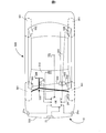
- FIG. 1 is an explanatory view showing a vehicle equipped with a braking assistance device according to the first embodiment
- FIG. 2 is a block diagram showing a functional configuration of a control device provided in the braking assistance device according to the first embodiment
- FIG. 3 is a flowchart showing a processing flow of braking support control executed by the braking support device according to the first embodiment
- FIG. 4 is an explanatory view for explaining an operation target area used in the first embodiment
- FIG. 5 is an explanatory view schematically showing the positional relationship between the host vehicle and the oncoming vehicle in the intersection in the first embodiment
- FIG. 6 is a flowchart showing a processing flow of braking support control executed by the braking support device according to the second embodiment.
- a braking assistance device in a vehicle and a braking assistance control method in a vehicle according to the present disclosure will be described below based on some embodiments.
- the braking assistance device 10 As shown in FIG. 1, the braking assistance device 10 according to the first embodiment is mounted on a vehicle 500 and used.
- the braking assistance device 10 includes a control device 100, millimeter wave radars 21 and 21s, a monocular camera 22, a yaw rate sensor 23, a wheel speed sensor 24, a steering angle sensor 25, and a braking assistance actuator 30.
- the vehicle 500 includes wheels 501, a braking device 502, a braking line 503, a steering wheel 504, a windshield 510, and a front bumper 520.
- the vehicle is provided with at least the monocular camera 22 of the millimeter wave radars 21 and 21s, the monocular camera 22 and the rider (LIDAR: laser radar) as a detection unit for detecting the state around the host vehicle.
- LIDAR laser radar
- the millimeter wave radars 21 and 21 s and the monocular camera 22 are provided as the detection unit.
- the state around the host vehicle includes an intersection, a traffic signal, a road marking, a road environment such as a road shape, and a traveling state of another vehicle.
- a braking device 502 is provided for each wheel 501.
- Each braking device 502 realizes the braking of each wheel 501 by the brake fluid pressure supplied via the braking line 503 according to the driver's brake pedal operation.
- the brake line 503 includes a brake piston and a brake fluid line that generate a brake fluid pressure according to the brake pedal operation.
- the brake assist actuator 30 is provided on the brake line 503, and hydraulic control can be performed independently of the operation of the brake pedal, whereby the brake assist is realized.
- a braking line 503 it replaces with a brake fluid line, makes it a control signal line, and the structure which operates the actuator with which each braking device 502 is equipped, and a brake by wire may be employ
- the steering wheel 504 is connected to the front wheel 501 via a steering mechanism 505 including a steering rod.
- the control device 100 includes a central processing unit (CPU) 101, a memory 102, an input / output interface 103, and a bus 104.
- the CPU 101, the memory 102, and the input / output interface 103 are bi-directionally connected via the bus 104.
- the memory 102 includes a memory for storing the braking support control program P1 for executing the braking support by the braking device 502 in a non-volatile and read only manner, such as a ROM, and a memory readable and writable by the CPU 101, for example a RAM. There is.
- the CPU 101 functions as a braking assistance control unit by developing the braking assistance control program P1 stored in the memory 102 into a readable / writable memory and executing the program.
- the braking assistance control unit may include a braking assistance actuator 30 that receives a control signal from the CPU 101 and applies a brake fluid pressure for braking assistance to the braking line 503.
- the braking assistance control unit executes the braking assistance control program P1 for controlling the execution of braking assistance and drives the CPU 101 as a control unit for transmitting control signals to the respective actuators and the braking device 502 for assisting braking. It is also possible to divide into the braking assistance actuator 30 as a drive part.
- the CPU 101 may be a single CPU, may be a plurality of CPUs that execute each program, or may be a multi-thread type CPU that can simultaneously execute a plurality of programs.
- millimeter wave radars 21 and 21s To the input / output interface 103, millimeter wave radars 21 and 21s, a monocular camera 22, a yaw rate sensor 23, a wheel speed sensor 24, a steering angle sensor 25 and a braking assistance actuator 30 are respectively connected via control signal lines. Detection information is input from the millimeter wave radars 21 and 21s, the monocular camera 22, the yaw rate sensor 23, the wheel speed sensor 24, and the steering angle sensor 25, and a control signal for instructing the braking level is output to the braking assistance actuator 30. Be done.
- the millimeter wave radars 21 and 21 s are sensors that emit millimeter waves and detect the distance, relative velocity, and angle of an object by receiving a reflected wave reflected by the object.
- the millimeter wave radar 21 is disposed at the center of the front bumper 520, and the two millimeter wave radars 21s are disposed on both sides of the front bumper 520, respectively.
- the detection signal output from the millimeter wave radars 21 and 21s is, for example, a point or a point train indicating one or more representative positions of an object whose reception wave has been processed by a processing circuit included in the millimeter wave radars 21 and 21s. It may be a signal or may be a signal indicating an unprocessed received wave. When an unprocessed received wave is used as a detection signal, signal processing for specifying the position and distance of an object is performed in the control device 100. A rider may be used instead of the millimeter wave radar.
- the single-eye camera 22 is an imaging device including one imaging element such as a CCD, and is a sensor that receives visible light and outputs external shape information of an object as image data as a detection result.
- the image data output from the monocular camera 22 is composed of a plurality of frame images that are continuous in time series, and each frame image is represented by pixel data.
- the monocular camera 22 is disposed at the upper center of the windshield 510.
- the pixel data output from the monocular camera 22 is monochrome pixel data or color pixel data. In addition, it may replace with the monocular camera 22, and the stereo camera of a compound eye may be used.
- the yaw rate sensor 23 is a sensor that detects the rotational angular velocity of the vehicle 500.
- the yaw rate sensor 23 is disposed, for example, at a central portion of the vehicle.
- the detection signal output from the yaw rate sensor 23 is a voltage value proportional to the rotation direction and the angular velocity.
- the wheel speed sensor 24 is a sensor that detects the rotational speed of the wheel 501, and is provided to each wheel 501.
- the detection signal output from the wheel speed sensor 24 is a voltage value proportional to the wheel speed or a pulse wave indicating an interval according to the wheel speed.
- the steering angle sensor 25 is a torque sensor that detects a twist amount generated on the steering rod by steering of the steering wheel 504, that is, a steering torque.
- the steering angle sensor 25 is provided on a steering rod that connects the steering wheel 504 and the steering mechanism.
- the detection signal output from the steering angle sensor 25 is a voltage value proportional to the amount of twist.
- the braking assistance actuator 30 is an actuator for realizing the braking by the braking device 502 regardless of the operation of the brake pedal by the driver.
- the brake support actuator 30 is mounted with a driver that controls the operation of the actuator based on a control signal from the CPU 101.
- the brake assisting actuator 30 is provided on the braking line 503, and increases or decreases the brake fluid pressure in the braking line 503 in accordance with a control signal from the control device 100.
- the braking assistance actuator 30 is configured of, for example, a module including an electric motor and a brake hydraulic piston driven by the electric motor. Alternatively, a braking control actuator that has already been introduced as an anti-slip device or anti-lock brake system may be used.
- the braking assistance processing performed by the braking assistance device 10 according to the first embodiment will be described with reference to FIGS. 3 to 5.
- the start switch is turned off after the start of the control system of the vehicle is stopped or after the start switch is turned on. Are repeatedly executed at predetermined time intervals.
- the situation shown in FIG. 4 will be described below as an example.
- the CPU 101 acquires the attribute of the object using the detection results input from the detection units such as the millimeter wave radars 21 and 21s and the single-eye camera 22 (step S100).
- the CPU 101 determines whether the target object is an oncoming vehicle using the acquired attribute (step S102).
- using the detection results from the millimeter wave radars 21 and 21s as the attribute for example, the distance from the vehicle M0 to the object, the relative velocity of the object to the vehicle M0, the direction of the object, Using, for example, the own vehicle M0, the lap rate between the own vehicle M0 and the object, the collision prediction time until collision with the object or the collision margin time (TTC) is calculated and acquired, and the image data from the monocular camera 22 is used.
- TTC collision margin time
- the relative position of the object to the object, and the shape and size of the object are calculated and obtained.
- the CPU 101 determines whether or not the object is an oncoming vehicle, using, for example, the relative velocity and the shape and size of the object among the acquired attributes.
- the oncoming vehicles M1 and M2 are detected as objects, and in the present embodiment, the oncoming vehicle means a vehicle traveling in front of the host vehicle M0.
- step 102 determines that the object is not an oncoming vehicle (step 102: No)
- the processing routine is ended and the processing routine is started at the next execution timing.
- Objects that are not oncoming vehicles are, for example, fixed objects on or beside roads, such as median dividers, guard rails, curbs. These objects can be determined not to be oncoming vehicles based on, for example, relative speed or shape or size, as would be readily understood by one skilled in the art.
- the CPU 101 determines whether the oncoming vehicles M1 and M2 exist in the operation target area FA where the braking assistance is to be performed (step S104).
- the operation target area FA is a region extending in the width direction orthogonal to the traveling direction and the traveling direction of the host vehicle M0, and the existence region of an object which may collide with or contact the host vehicle M0. Means For example, when the traveling direction of the host vehicle M0 is Y axis and the lateral direction of the host vehicle M0 is X axis, the distance of the operation target area FA in the Y axis direction is until the vehicle collides with the oncoming vehicle.
- TTC TTC
- the distance is variable according to the speed v of the vehicle M0.
- the oncoming vehicle is to be monitored or avoided with room to improve the effectiveness of collision avoidance or contact avoidance.
- the distance in the Y-axis direction from the own vehicle M0 exceeds a predetermined distance
- the distance in the lateral direction balances the suppression of the increase of the oncoming vehicle to be monitored and the effectiveness of collision avoidance. It may be a fixed distance.
- the oncoming vehicle M1 exists in the operation target area FA, and the oncoming vehicle M2 does not exist in the operation target area FA.
- the CPU 101 performs X coordinates of the coordinates of the detection point TP corresponding to the widthwise center of the oncoming vehicles M1 and M2 in the width direction of the oncoming vehicles M1 and M2 and coordinates of the width direction center of the front of the vehicle M0. Using the X coordinate, it is determined whether the oncoming vehicle M1 or M2 exists in the range of the operation target area FA in the X axis direction.
- the CPU 101 detects the detection point TP input from the millimeter wave radars 21 and 21s in the front area of the vehicle extracted from the image data input from the monocular camera 22 by data fusion processing. Coordinate positions may be superimposed.
- the coordinate values of the detection points are superimposed on the front area of the vehicle extracted from the image data, so that the oncoming vehicle M1 with respect to the host vehicle M0, The coordinates of the closest end of M2 are determined, and the oncoming vehicles M1 and M2 exist in the operation target area FA using the distance between the coordinates of the closest end and the coordinates of the end in the width direction closest to the oncoming vehicle of the vehicle. It may be determined whether to do so.
- the closest end is the end of the oncoming vehicle M1, M2 located at the closest distance to the host vehicle M0, and in the case of left-handed traffic, the right front end of the oncoming vehicle M1, M2 is right-handed In this case, the left front end of the oncoming vehicle M1, M2 corresponds.
- the left-handed passage will be described below as an example.
- step S104 determines that the oncoming vehicle M1, M2 does not exist in the operation target area FA (step S104: No). If the CPU 101 determines that the oncoming vehicles M1 and M2 exist in the operation target area FA (step S104: Yes), the own vehicle position is acquired (step S106), and it is determined whether the own vehicle M0 exists in the intersection. It determines (step S108). Specifically, the CPU 101 determines, using the detection results from the millimeter wave radars 21 and 21s and the single-eye camera 22, whether or not the position of the host vehicle M0 is in the intersection IS, as shown in FIG.
- Whether or not the own vehicle M0 exists in the intersection IS is detected by the millimeter wave radars 21 and 21 s, for example, using the traffic light SG detected by the single-eye camera 22 and the intersection mark ISM on the road. It can be determined using the road shape. In addition, information from light beacons, global positioning system (GPS) and map information in the navigation system may be used to determine an approach to an intersection.
- GPS global positioning system
- the first threshold T1 indicating the first braking timing as the determination threshold Tb of the collision prediction time TTC ( s) is set (step S110), and the process proceeds to step S122.
- the braking timing is the timing to start the braking support
- the first threshold T1 is the braking support for the collision avoidance with the object or the reduction of the damage due to the contact while the host vehicle M0 is traveling on the road other than the intersection.
- the braking assistance includes the case where the speed of the own vehicle M0 is reduced as well as the case where the own vehicle M0 is completely stopped (0 km / h).
- the CPU 101 determines whether the oncoming vehicles M1 and M2 are straight-ahead vehicles (step S112).
- the oncoming vehicle M1 corresponds to a turning vehicle
- the oncoming vehicle M2 corresponds to a straight-ahead vehicle.
- Whether or not the oncoming vehicle M1, M2 is a straight-ahead vehicle can be determined, for example, by detecting the direction of the oncoming vehicle M1, M2.
- the CPU 101 uses the detection points inputted from the millimeter wave radars 21 and 21s and the width dimension of the front of the vehicle according to the distance from the own vehicle M0 prepared in advance, and the front of the oncoming vehicle Identify coordinate values corresponding to When there is a detection point corresponding to the side surface of the vehicle which exceeds the lateral width of the front of the vehicle specified in the X-axis direction, the CPU 101 corresponds to the total length dimension of the vehicle prepared in the vertical direction, that is, the Y-axis direction. Identify a detection point that is less than the coordinate value.
- the CPU 101 specifies the directions of the oncoming vehicles M1 and M2 from the inclination of a straight line connecting the coordinate values of the end points of the width in front of the vehicle and the coordinate values of the detection points corresponding to the vehicle side.
- the CPU 101 superimposes the coordinate positions of the detection points input from the millimeter wave radars 21 and 21s on the front area and the side area of the vehicle extracted from the image data input from the single-eye camera 22 by data fusion processing.
- the directions of the oncoming vehicles M1 and M2 may be specified using the coordinate values of the detection points.
- the CPU 101 sets a second threshold T2 (s) indicating a second braking timing as the determination threshold Tb (step S114). ), And proceeds to step S122.
- the second braking timing is a braking timing that is later than the first braking timing, that is, a braking timing that the braking start timing is temporally later than the first braking timing.
- the second threshold T2 corresponding to the second braking timing has a relationship of T2 ⁇ T1 with the first threshold T1. Note that, instead of setting the second threshold T2, setting may be made so as not to execute the braking support itself.
- Step S112 determines that the oncoming vehicle M1 is a straight-ahead vehicle (step S112: No)
- a turning vehicle means a right-turn vehicle in the case of left-handed traffic and a left-turn vehicle in the case of right-handed traffic, which travels so as to cross the route of the host vehicle M0.
- the CPU 101 determines that the oncoming vehicle M1 is not likely to stop, that is, the oncoming vehicle M1 is a simple turning vehicle (step S116: No)
- the third braking timing is indicated as the determination threshold Tb.
- the third threshold T3 (s) is set (step S118), and the process proceeds to step S122.
- Whether the oncoming vehicle M1 may stop may be determined, for example, whether the relative speed of the oncoming vehicle M1 to the host vehicle M0 is decreasing with time, that is, whether the oncoming vehicle M1 is decelerating, or The determination is made based on whether the vehicle speed of the oncoming vehicle M1 is 0 km / h.
- the CPU 101 determines that the oncoming vehicle M1 may stop when the relative speed of the oncoming vehicle M1 with respect to the host vehicle M0 is decreasing with time, and the vehicle speed of the oncoming vehicle M1 is already 0 km / h Also in the case, it is determined that the oncoming vehicle M1 may stop.
- the third braking timing is a braking timing later than the second braking timing, that is, a braking timing later than the second braking timing.
- the third threshold T3 corresponding to the third braking timing has a relationship of T3 ⁇ T2 with the second threshold T2.
- the CPU 101 determines that the oncoming vehicle M1 may stop, that is, if the oncoming vehicle M1 is a turning vehicle that stops at the intersection for a right turn (step S116: Yes), it is determined as the determination threshold Tb.
- the fourth threshold T4 (s) indicating the fourth braking timing is set (step S120), and the process proceeds to step S122.
- the fourth braking timing is a braking timing later than the third braking timing, that is, a braking timing later in time than the third braking timing. In the case where the oncoming vehicle M1 is a turning vehicle that temporarily stops at an intersection, the turning vehicle is stopped while the oncoming vehicle M0 and the oncoming vehicle M1 are closest to each other, so that the start timing of the braking assistance is further delayed.
- the fourth threshold T4 corresponding to the fourth braking timing has a relationship of T4 ⁇ T3 with the third threshold T3.
- a setting may be made so as not to execute the braking support itself.
- the CPU 101 determines the predicted collision time TTC of the own vehicle M0 with respect to the oncoming vehicles M1 and M2, and determines whether or not the relationship of TTC ⁇ Tb holds, that is, starts the braking of the own vehicle M0 and starts with the oncoming vehicle M1 and M2. It is determined whether contact or collision should be avoided (step S122). If the CPU 101 determines that the relationship of TTC ⁇ Tb is not established (step S122: No), the processing routine is ended and the processing routine is started at the next execution timing.
- the processing routine is ended. Specifically, the CPU 101 transmits a control signal instructing the brake assisting actuator 30 to increase the brake fluid pressure, and operates the braking device 502 to execute braking.
- the braking assistance is ended, for example, by complete stop of the host vehicle M0, that is, when the CPU 101 detects the vehicle speed 0 km / h via the wheel speed sensor 24, or when the relationship of TTC> Tb is established. .
- the braking timing of the braking assistance is determined according to the state around the host vehicle M0. Therefore, it is possible to improve the accuracy of avoiding contact or collision between the host vehicle M0 going straight at the intersection and another vehicle, and the accuracy of reducing the influence due to the collision or contact. Specifically, whether the oncoming vehicle is a straight-ahead vehicle or a turning vehicle if the own vehicle M0 exists in the intersection IS based on whether the own vehicle M0 exists in the intersection IS The determination threshold value Tb is set on the basis of the determination of and the determination whether there is a possibility of stopping in the case of a turning vehicle.
- the host vehicle M0 travels straight on the intersection IS, it is possible to set the execution timing of the braking assistance with high accuracy based on the attribute of whether the oncoming vehicle is a straight traveling vehicle or a turning vehicle. If the attribute of the oncoming vehicle, which is a vehicle, indicates the possibility of stopping, it is possible to further delay the execution timing of the braking support. As a result, the timing at which the execution of the braking support is required is accurately set at the three-stage timing according to the attribute of the oncoming vehicle at the intersection IS, and the execution frequency of the braking support in the intersection is reduced. It is possible to improve the accuracy of avoiding contact or collision, and the accuracy of reducing the influence of collision or damage caused by contact.
- a braking assistance device according to a second embodiment will be described with reference to FIG.
- the braking assistance device according to the second embodiment has the same configuration and processing as the braking assistance device 10 according to the first embodiment except that the attribute of the oncoming vehicle used for assisting braking is different.
- it is determined whether or not the own vehicle M0 is present in the intersection IS, and when it is determined that the own vehicle M0 is present in the intersection, the oncoming vehicle may stop.
- the determination threshold value Tb is set based on the determination as to whether or not there is a sex, and the determination as to whether the oncoming vehicle is a straight ahead vehicle or a turning vehicle is not executed. It differs from the support device 10. Therefore, the same components and processes as those of the braking assistance device 10 according to the first embodiment are denoted by the reference numerals and step numbers used in the first embodiment, and the description thereof is omitted, and different processing steps are performed. It will be described below.
- the start switch is turned off after the start of the control system of the vehicle is turned on or after the start switch is turned on.
- the braking assistance control program P1 includes steps S121a to S121c as processing steps in place of steps S112 to S120 in the first embodiment.
- the CPU 101 executes steps S100 to S108, and in step S108, when determining that the host vehicle M0 is present in the intersection IS (step S108: Yes), determines whether or not the oncoming vehicle may stop ( Step S121a).
- the method of determining whether or not the oncoming vehicle may stop is as described in the first embodiment. If the CPU 101 determines that there is no possibility that the oncoming vehicle will stop (step S121a: No), the second threshold T2 (s) indicating the second braking timing is set as the determination threshold Tb (step In step S121 b), the process proceeds to step S122.
- the second threshold T2 has a relationship of T2 ⁇ T1 with the first threshold T1.
- a third threshold T3 smaller than the second threshold T2 may be used.
- the host vehicle M0 travels in the intersection IS
- the possibility of collision or contact is low when the oncoming vehicle is a straight traveling vehicle (M2)
- the oncoming vehicle is a turning vehicle (M1)
- the start timing of the braking support is further delayed by using the threshold value matched to the turning vehicle, and the execution of the braking support is suppressed to give the occupant an unpleasant feeling. Further reduction can be achieved.
- step S121a If the CPU 101 determines that there is a possibility that the oncoming vehicle may stop (step S121a: Yes), the fourth threshold T4 (s) indicating the fourth braking timing is set as the determination threshold Tb (step In step S121c), the process proceeds to step S122.
- the fourth braking timing is a braking timing later than the second braking timing, and the fourth threshold T4 corresponding to the fourth braking timing has a relationship of T4 ⁇ T2 with the second threshold T2. Have.
- the oncoming vehicle When there is a possibility that the oncoming vehicle may stop temporarily at the intersection, the oncoming vehicle is likely to be a turning vehicle (M1), and while the oncoming vehicle stops while being closest to the own vehicle M0, the start timing of the braking assistance By delaying the delay time, the execution of the braking support can be suppressed and the discomfort given to the occupant can be reduced.
- a setting may be made so as not to execute the braking support itself.
- the braking timing of the braking assistance is determined according to the state around the host vehicle M0. Therefore, it is possible to improve the accuracy of avoiding contact or collision between the host vehicle M0 going straight at the intersection and another vehicle, and the accuracy of reducing the influence due to the collision or contact. Specifically, whether or not the oncoming vehicle may stop when the own vehicle M0 exists in the intersection IS, based on whether the own vehicle M0 exists in the intersection IS Based on the determination, the determination threshold Tb is set.
- the host vehicle M0 travels straight ahead at the intersection IS, it is possible to delay the execution timing of the braking support regardless of the attribute of the oncoming vehicle, and when the attribute of the oncoming vehicle indicates the possibility of stopping It is possible to further delay the execution timing of the braking support.
- the timing at which the execution of the braking assistance is required at the intersection IS can be set accurately, and the frequency of the execution of the braking assistance at the intersection can be reduced and the contact or collision with the oncoming vehicle can be avoided.
- the attribute of the object is the detection signal or image data from the millimeter wave radar 21 or 21s as the object detection unit, the monocular camera 22, or the rider and the stereo camera It is determined using.
- the object is an oncoming vehicle
- data on the behavior of the other vehicle acquired via the inter-vehicle communication system for example, the steering angle, the accelerator opening degree, and the brake operation amount
- the attributes of M1 and M2 may be determined.
- the oncoming vehicle is a straight traveling vehicle after determining that there is no possibility that the oncoming vehicle will stop. If it is determined that the vehicle is a straight ahead vehicle, the second threshold T2 may be used, and if it is determined that the vehicle is a cornering vehicle, the third threshold T3 may be used.
- the execution start timing of the braking support is changed according to the state around the host vehicle, that is, the road environment in which the host vehicle is present and the attribute of the oncoming vehicle.
- the level of the braking support for example, the braking force may be changed.
- the braking level may be raised as the threshold value Tx becomes a small value, and the braking assistance may be set so as to sufficiently avoid a collision or contact with the oncoming vehicle.
- the CPU 101 executes the braking assistance control program P1 to realize the braking assistance control unit in software. It may be realized in hardware by discrete circuits.
- the braking assistance device in the vehicle according to the first aspect is application example 1; Application Example 2 The vehicle braking assistance device according to Application Example 1; The braking support device for a vehicle, wherein the braking support control unit executes the braking support at the second braking timing or does not execute the braking support when the oncoming vehicle detected by the detection unit is a straight-ahead vehicle .
- Application Example 3 The vehicle braking assistance device according to Application Example 1 or 2. The vehicle according to the present invention, wherein the braking assistance control unit executes the braking assistance at a third braking timing later than the second braking timing when the detected oncoming vehicle is a turning vehicle crossing the own lane. Braking support device.
- Application Example 4 The vehicle braking assistance device according to Application Example 3, wherein The braking support control unit executes braking support or does not execute braking support at a fourth braking timing later than the third braking timing when there is a possibility that the detected oncoming vehicle may stop.
- Application Example 5 The vehicle braking assistance device according to Application Example 1, wherein The braking support control unit performs the braking at a third braking timing later than the second braking timing or the second braking timing when there is no possibility that the oncoming vehicle detected by the detection unit may stop. Vehicle braking support device that performs support.
- Application Example 6 The vehicle braking assistance device according to Application Example 1 or 5.
- the braking assistance control unit executes the braking assistance at a fourth braking timing later than the second braking timing when there is a possibility that the oncoming vehicle detected by the detecting unit may stop, or Braking support device that does not perform support.
Landscapes
- Engineering & Computer Science (AREA)
- Transportation (AREA)
- Mechanical Engineering (AREA)
- Physics & Mathematics (AREA)
- General Physics & Mathematics (AREA)
- Regulating Braking Force (AREA)
- Traffic Control Systems (AREA)
Abstract
車両における制動支援装置10が提供される。制動支援装置10は、自車両の周囲の状態を検出するための検出部21、21s、22と、検出された状態に応じて第1の制動タイミングで制動支援を実行して自車両を制動する制動支援制御部100とを備える。制動支援制御部100は、状態を用いて自車両が交差点を進行していると判定した場合には、第1の制動タイミングよりも遅い第2の制動タイミングにて制動支援を実行する。
Description
本願は、その全ての開示が参照によりここに組み込まれる、2017年7月11日に出願された、日本国特許出願 出願番号2017-135115に基づく優先権を主張する。
本開示は車両における制動支援装置および制動支援制御方法に関する。
カメラやレーダといった対象物検出器からの検出結果を用いて、自車両の前方に存在する他車両や障害物といった対象物との接触や衝突を回避するための接触回避技術が実用化されている。接触回避技術には、検出結果を用いて車両の制動支援を行う制動支援技術も含まれており、例えば、信号機の灯色や停止線を識別して自車両を停止させる制動支援や、交差点や左側通行国における右折用レーンにおいて、自車両に対向する他車両との接触や衝突を回避、軽減するために自車両を停止させる制動支援が提案されている(例えば、特開2009-166764号公報、特開2010-280271号公報)。
しかしながら、交差点においては交差点以外の道路と比較して、直進する自車両の進行車線に対して交差進行、すなわち、旋回進行する他車両との遭遇確率が高くなり、自車両と旋回進行する他車両との接触や衝突を回避、あるいは、接触や衝突による影響を軽減することが求められる状況も増大する。一方で、増大する他車両との接触や衝突を考慮して制動支援の頻度が高くなると制動支援に伴う自車両の減速や停止の機会が増大し自車両の乗員に不快感を与えると共に、交差点における車両の円滑な進行が妨げられる。
したがって、交差点において直進する自車両と他車両との接触や衝突の回避の精度、衝突や接触に伴う影響を軽減する精度を向上することが望まれている。
本開示は、以下の態様として実現することが可能である。
第1の態様は、車両の制動支援装置を提供する。第1の態様に係る車両の制動支援装置は、自車両の周囲の状態を検出するための検出部と、検出された前記状態に応じて第1の制動タイミングで制動支援を実行して自車両を制動する制動支援制御部であって、前記状態を用いて自車両が交差点を進行していると判定した場合には、前記第1の制動タイミングよりも遅い第2の制動タイミングにて前記制動支援を実行する制動支援制御部と、を備える。
第1の態様に係る車両の制動支援装置によれば、自車両の周囲の状態を検出し、検出された状態に応じて第1の制動タイミングで制動支援を実行する際に、状態を用いて自車両が交差点を進行していると判定した場合には、第1の制動タイミングよりも遅い第2の制動タイミングにて制動支援を実行するので、交差点において直進する自車両と他車両との接触や衝突の回避の精度、衝突や接触に伴う影響を軽減する精度を向上することができる。
第2の態様は、車両における制動支援制御方法を提供する。第2の態様に係る車両における制動支援制御方法は、自車両の周囲の状態を検出し、検出された前記状態に応じて第1の制動タイミングで制動支援を実行する際に、前記状態を用いて自車両が交差点を進行していると判定した場合には、前記第1の制動タイミングよりも遅い第2の制動タイミングにて前記制動支援を実行すること、を備える。
第2の態様係る車両における制動支援制御方法によれば、自車両の周囲の状態を検出し、検出された状態に応じて第1の制動タイミングで制動支援を実行する際に、状態を用いて自車両が交差点を進行していると判定した場合には、第1の制動タイミングよりも遅い第2の制動タイミングにて制動支援を実行するので、交差点において直進する自車両と他車両との接触や衝突の回避の精度、衝突や接触に伴う影響を軽減する精度を向上することができる。なお、本開示は、車両の制動支援制御プログラムまたは当該プログラムを記録するコンピュータ読み取り可能記録媒体としても実現可能である。
本開示についての上記目的およびその他の目的、特徴や利点は、添付の図を参照しながら下記の詳細な記述により、より明確となる。その図は、
図1は第1の実施形態に係る制動支援装置が搭載された車両を示す説明図であり、
図2は第1の実施形態に係る制動支援装置が備える制御装置の機能的構成を示すブロック図であり、
図3は第1の実施形態に係る制動支援装置によって実行される制動支援制御の処理フローを示すフローチャートであり、
図4は第1の実施形態において用いられる作動対象エリアを説明するための説明図であり、
図5は第1の実施形態における、交差点内における自車両と対向車両と位置関係を模式的に示す説明図であり、
図6は第2の実施形態に係る制動支援装置によって実行される制動支援制御の処理フローを示すフローチャートである。
本開示に係る車両における制動支援装置および車両における制動支援制御方法について、いくつかの実施形態に基づいて以下説明する。
第1の実施形態:
図1に示すように、第1の実施形態に係る制動支援装置10は、車両500に搭載されて用いられる。制動支援装置10は、制御装置100、ミリ波レーダ21、21s、単眼カメラ22、ヨーレートセンサ23、車輪速度センサ24、舵角センサ25、制動支援アクチュエータ30を備えている。車両500は、車輪501、制動装置502、制動ライン503、ステアリングホイール504、フロントガラス510およびフロントバンパ520を備えている。なお、車両は、自車両の周囲の状態を検出するための検出部として、ミリ波レーダ21、21s、単眼カメラ22、および、ライダー(LIDAR:レーザレーダ)のうち少なくとも単眼カメラ22を備えていれば良く、本実施形態においては、ミリ波レーダ21、21s、および単眼カメラ22が検出部として備えられている。本実施形態において、自車両の周囲の状態とは、交差点、信号機、道路標示、道路形状といった道路環境、他車両の走行状態を含む状態である。
図1に示すように、第1の実施形態に係る制動支援装置10は、車両500に搭載されて用いられる。制動支援装置10は、制御装置100、ミリ波レーダ21、21s、単眼カメラ22、ヨーレートセンサ23、車輪速度センサ24、舵角センサ25、制動支援アクチュエータ30を備えている。車両500は、車輪501、制動装置502、制動ライン503、ステアリングホイール504、フロントガラス510およびフロントバンパ520を備えている。なお、車両は、自車両の周囲の状態を検出するための検出部として、ミリ波レーダ21、21s、単眼カメラ22、および、ライダー(LIDAR:レーザレーダ)のうち少なくとも単眼カメラ22を備えていれば良く、本実施形態においては、ミリ波レーダ21、21s、および単眼カメラ22が検出部として備えられている。本実施形態において、自車両の周囲の状態とは、交差点、信号機、道路標示、道路形状といった道路環境、他車両の走行状態を含む状態である。
車両500において、制動装置502は、各車輪501に備えられている。各制動装置502は、運転者の制動ペダル操作に応じて制動ライン503を介して供給されるブレーキ液圧によって各車輪501の制動を実現する。制動ライン503には制動ペダル操作に応じたブレーキ液圧を発生させるブレーキピストンおよびブレーキ液ラインが含まれる。本実施形態においては、制動支援アクチュエータ30が制動ライン503に備えられ、制動ペダル操作とは独立して液圧制御が可能であり、これにより制動支援が実現される。なお、制動ライン503としては、ブレーキ液ラインに代えて、制御信号線とし、各制動装置502に備えられているアクチュエータを作動させる構成、ブレーキバイワイヤが採用されても良い。ステアリングホイール504は、ステアリングロッドを含む操舵機構505を介して前側の車輪501と接続されている。
図2に示すように、制御装置100は、中央処理装置(CPU)101、メモリ102、入出力インタフェース103およびバス104を備えている。CPU101、メモリ102および入出力インタフェース103はバス104を介して双方向通信可能に接続されている。メモリ102は、制動装置502による制動の支援を実行するための制動支援制御プログラムP1を不揮発的且つ読み出し専用に格納するメモリ、例えばROMと、CPU101による読み書きが可能なメモリ、例えばRAMとを含んでいる。CPU101はメモリ102に格納されている制動支援制御プログラムP1を読み書き可能なメモリに展開して実行することによって制動支援制御部として機能する。なお、制動支援制御部には、CPU101からの制御信号を受けて制動ライン503に対して制動支援のためのブレーキ液圧を印加する制動支援アクチュエータ30が含まれても良い。また、制動支援制御部は、制動支援の実行を制御する制動支援制御プログラムP1を実行して各アクチュエータに対して制御信号を送信する制御部としてのCPU101および制動支援のために制動装置502を駆動する駆動部としての制動支援アクチュエータ30に区分することも可能である。CPU101は、単体のCPUであっても良く、各プログラムを実行する複数のCPUであっても良く、あるいは、複数のプログラムを同時実行可能なマルチスレッドタイプのCPUであっても良い。
入出力インタフェース103には、ミリ波レーダ21、21s、単眼カメラ22、ヨーレートセンサ23、車輪速度センサ24、舵角センサ25および制動支援アクチュエータ30がそれぞれ制御信号線を介して接続されている。ミリ波レーダ21、21s、単眼カメラ22、ヨーレートセンサ23、車輪速度センサ24および舵角センサ25からは、検出情報が入力され、制動支援アクチュエータ30に対しては制動レベルを指示する制御信号が出力される。
ミリ波レーダ21、21sはミリ波を射出し、対象物によって反射された反射波を受信することによって対象物の距離、相対速度および角度を検知するセンサである。本実施形態において、ミリ波レーダ21は、フロントバンパ520の中央に配置され、2つのミリ波レーダ21sはそれぞれフロントバンパ520の両側面に配置されている。ミリ波レーダ21、21sから出力される検出信号は、例えば、ミリ波レーダ21、21sが備える処理回路において受信波が処理された対象物の1または複数の代表位置を示す点または点列からなる信号であっても良く、あるいは、未処理の受信波を示す信号であっても良い。未処理の受信波が検出信号として用いられる場合には、制御装置100において対象物の位置および距離を特定するための信号処理が実行される。なお、ミリ波レーダに代えて、ライダーが用いられても良い。
単眼カメラ22は、CCD等の撮像素子を1つ備える撮像装置であり、可視光を受光することによって対象物の外形情報を検出結果である画像データとして出力するセンサである。単眼カメラ22から出力される画像データは、時系列的に連続する複数のフレーム画像によって構成されており、各フレーム画像は画素データにより表されている。本実施形態において、単眼カメラ22はフロントガラス510の上部中央に配置されている。単眼カメラ22から出力される画素データは、モノクロの画素データまたはカラーの画素データである。なお、単眼カメラ22に代えて複眼のステレオカメラが用いられても良い。
ヨーレートセンサ23は、車両500の回転角速度を検出するセンサである。ヨーレートセンサ23は、例えば、車両の中央部に配置されている。ヨーレートセンサ23から出力される検出信号は、回転方向と角速度に比例する電圧値である。
車輪速度センサ24は、車輪501の回転速度を検出するセンサであり、各車輪501に備えられている。車輪速度センサ24から出力される検出信号は、車輪速度に比例する電圧値または車輪速度に応じた間隔を示すパルス波である。車輪速度センサ24からの検出信号を用いることによって、車両速度、車両の走行距離等の情報を得ることができる。
舵角センサ25は、ステアリングホイール504の操舵によりステアリングロッドに生じるねじれ量、すなわち、操舵トルク、を検出するトルクセンサである。本実施形態において、舵角センサ25は、ステアリングホイール504と操舵機構とを接続するステアリングロッドに備えられている。舵角センサ25から出力される検出信号は、ねじれ量に比例する電圧値である。
制動支援アクチュエータ30は、運転者による制動ペダル操作とは無関係に制動装置502による制動を実現するためのアクチュエータである。制動支援アクチュエータ30には、CPU101からの制御信号に基づきアクチュエータの動作を制御するドライバが実装されている。本実施形態において、制動支援アクチュエータ30は、制動ライン503に備えられており、制御装置100からの制御信号に従って制動ライン503におけるブレーキ液圧を増減させる。制動支援アクチュエータ30は、例えば、電動モータと電動モータにより駆動されるブレーキ液圧ピストンとを備えるモジュールから構成されている。あるいは、横滑り防止装置、アンチロックブレーキシステムとして既に導入されている制動制御アクチュエータが用いられても良い。
図3から図5を参照して、第1の実施形態に係る制動支援装置10により実行される制動支援処理について説明する。図3に示す処理ルーチンは、CPU101が制動支援制御プログラムP1を実行することによって、例えば、車両の制御システムの始動時から停止時まで、または、スタートスイッチがオンされてからスタートスイッチがオフされるまで、所定の時間間隔にて繰り返して実行される。図4に示す状況を例にとって以下説明する。
CPU101は、ミリ波レーダ21、21s、単眼カメラ22といった検出部から入力される検出結果を用いて対象体の属性を取得する(ステップS100)。CPU101は、取得された属性を用いて対象体が対向車両であるか否かを判定する(ステップS102)。本実施形態において、属性としては、ミリ波レーダ21、21sからの検知結果を用いて、例えば、自車両M0から対象物までの距離、自車両M0に対する対象体の相対速度、対象物の向き、自車両M0と対象物とのラップ率、対象物と衝突するまでの衝突予測時間または衝突余裕時間(TTC)が算出、取得され、単眼カメラ22からの画像データを用いて、例えば、自車両M0に対する対象物の相対位置、対象物の形状や大きさが算出、取得される。CPU101は、取得した属性の内、例えば、相対速度や、対象物の形状や大きさを用いて、対象物が対向車両であるか否かを判定する。図4に示す例では、対向車両M1、M2が対象体として検出される、本実施形態において対向車両とは、自車両M0に対して対向して進行中の車両を意味する。
CPU101は、対象物が対向車両でないと判定すると(ステップ102:No)、本処理ルーチンを終了して次回の実行タイミングで本処理ルーチンを開始する。対向車両でない対象物は、例えば、中央分離帯、ガードレール、縁石といった道路上または道路脇の固定物である。これらの対象物は、例えば、当業者によって容易に理解されるように、相対速度や形状または大きさに基づいて対向車両でないことを判別可能である。
CPU101は、対象物が対向車両であると判定すると(ステップ102:Yes)、対向車両M1、M2が制動支援を実行すべき作動対象エリアFA内に存在するか否かを判定する(ステップS104)。図4に示すように、作動対象エリアFAは、自車両M0の進行方向および進行方向に直交する幅方向に広がる領域であり、自車両M0と衝突または接触の可能性がある対象物の存在領域を意味する。例えば、自車両M0の進行方向をY軸とし、自車両M0の幅方向、すなわち、横方向をX軸とする場合、作動対象エリアFAのY軸方向の距離は、対向車両と衝突するまでのTTCによって規定され、作動対象エリアFAのX軸方向の距離は、例えば、自車両M0から離間するに連れて横方向に広がりを持つように規定されている。TTC(s)は、移動距離DL(km)および自車両速度v(km/h)を用いて、TTC=DL/vにより算出され、作動対象エリアFAのY軸方向の距離は、TTCを定めておくことで、自車両M0の速度vによって可変する距離である。一方、作動対象エリアFAのX軸方向の距離は、自車両M0から離間するに連れて対向車両の動きを精度良く予測することは容易でなくなるため、自車両M0から離間するに連れて横方向に余裕を持って対向車両を監視対象または回避対象とし、衝突回避または接触回避の実効性を向上させる。なお、横方向への距離は、監視対象となる対向車両の増大の抑制と衝突回避の実効性とのバランスを図り、自車両M0からのY軸方向の距離が予め定められた距離を超えると一定距離とされても良い。図4の例では、対向車両M1は作動対象エリアFAに存在し、対向車両M2は作動対象エリアFAに存在しない。
対向車両M1、M2が作動対象エリアFAに存在するか否かの判定手法の一例について説明する。CPU101は、ミリ波レーダ21、21sから入力された対向車両M1、M2の車両正面の幅方向中央に相当する検出点TPの座標のX座標と自車両M0の車両正面の幅方向中央の座標のX座標とを用いて対向車両M1、M2が作動対象エリアFAのX軸方向の範囲に存在するか否かを判定する。すなわち、自車両M0の車両正面の幅方向中央のX座標と、検出点のX座標との差分距離が、予め定められた作動対象エリアFAのX軸方向の距離以下であるか否かが判定される。なお、CPU101は、精度を向上させるために、データフュージョン処理により、単眼カメラ22から入力される画像データから抽出された車両の正面領域に、ミリ波レーダ21、21sから入力された検出点TPの座標位置を重ね合わせても良い。ミリ波レーダ21、21sから複数の検出点が入力される場合には、画像データから抽出された車両の正面領域に各検出点の座標値を重ね合わせることで、自車両M0に対する対向車両M1、M2の最近接端部の座標を求め、最近接端部の座標と自車両の対向車両に最近接する幅方向端部の座標との距離を用いて対向車両M1、M2が作動対象エリアFAに存在するか否かが判定されても良い。最近接端部とは、自車両M0に対して最も近い距離にある対向車両M1、M2の端部であり、左側通行の場合には、対向車両M1、M2の右前端部が、右側通行の場合には、対向車両M1、M2の左前端部が該当する。なお、本実施形態では、説明を簡易にするため以下、左側通行を例にとって説明する。
CPU101は、対向車両M1、M2が作動対象エリアFA内に存在しないと判定すると(ステップS104:No)、本処理ルーチンを終了して次回の実行タイミングで本処理ルーチンを開始する。CPU101は、対向車両M1、M2が作動対象エリアFA内に存在すると判定すると(ステップS104:Yes)、自車両位置を取得し(ステップS106)、自車両M0が交差点内に存在するか否かを判定する(ステップS108)。具体的には、CPU101は、ミリ波レーダ21、21s、単眼カメラ22からの検出結果を用いて、図5に示すように自車両M0の位置が交差点IS内であるか否かを判定する。自車両M0が交差点IS内に存在するか否かは、例えば、単眼カメラ22によって検出された信号機SG、道路上における交差点標記ISMを用いて、さらには、ミリ波レーダ21、21sによって検出された道路形状を用いて判定することができる。加えて、光ビーコンからの情報、グローバルポジショニングシステム(GPS)およびナビゲーションシステムにおける地図情報を用いて交差点への進入が判定されても良い。
CPU101は、自車両M0が交差点IS内に存在しないと判定した場合には(ステップS108:No)、衝突予測時間TTCの判定しきい値Tbとして第1の制動タイミングを示す第1の閾値T1(s)を設定して(ステップS110)、ステップS122に移行する。制動タイミングとは、制動支援を開始するタイミングであり、第1の閾値T1は、自車両M0が交差点以外の道路を走行中に、対象物との衝突回避または接触による損傷軽減のために制動支援を実行開始するタイミングを規定する。なお、本実施形態において、制動支援には、自車両M0を完全に停止(時速0km/h)させる場合の他、自車両M0の速度を減速させる場合も含まれる。
CPU101は、自車両M0が交差点IS内に存在すると判定した場合には(ステップS108:Yes)、対向車両M1、M2が直進車両であるか否かを判定する(ステップS112)。図5の例では、対向車両M1は旋回車両、対向車両M2は直進車両に相当する。対向車両M1、M2が直進車両であるか否かは、例えば、対向車両M1、M2の向きを検出することによって判定され得る。具体的には、CPU101は、ミリ波レーダ21、21sから入力される検出点と、予め用意されている自車両M0からの距離に応じた車両正面の横幅寸法とを用いて対向車両の車両正面に相当する座標値を特定する。CPU101は、X軸方向に特定した車両正面の横幅を超える車両側面に相当する検出点が存在する場合、縦方向、すなわち、Y軸方向の座標値が予め用意された車両の全長寸法に相当する座標値未満である検出点を特定する。CPU101は、車両正面の横幅の端点の座標値と車両側面に相当する検出点の座標値を結ぶ直線の傾きから対向車両M1、M2の向きを特定する。また、CPU101は、データフュージョン処理により、単眼カメラ22から入力される画像データから抽出された車両の正面領域および側面領域に、ミリ波レーダ21、21sから入力された各検出点の座標位置を重ね合わせ、各検出点の座標値を用いて対向車両M1、M2の向きを特定しても良い。
CPU101は、対向車両M2が直進車両であると判定すると(ステップS112:Yes)、判定しきい値Tbとして、第2の制動タイミングを示す第2の閾値T2(s)を設定して(ステップS114)、ステップS122に移行する。第2の制動タイミングは、第1の制動タイミングよりも遅い制動タイミング、すなわち、制動開始時期が第1の制動タイミングよりも時間的に遅い制動タイミングである。自車両M0が交差点IS内を進行している際には、交差点以外の道路を走行している場合よりも対向車両M1、M2と近接する可能性があり、また、自車両M0と近接する対向車両M1、M2の車速は低くなる傾向にあるので、制動支援の開始時期を遅延させることによって制動支援の実行を抑制し、乗員に与える不快感の低減が図られる。第2の制動タイミングに対応する第2の閾値T2は、第1の閾値T1との間に、T2<T1の関係を有している。なお、第2の閾値T2の設定に代えて、制動支援自体を実行しない設定がなされても良い。
CPU101は、対向車両M1が直進車両でないと判定すると(ステップS112:No)、対向車両M1は旋回車両であると判定し、更に対向車両M1は停止する可能性があるか否かを判定する(ステップS116)。対向車両M1が直進車両でないと判定された場合には、対向車両M1は旋回車両であると判定される。なお、対向車両が直進車両であるか旋回車両であるかは、自車両M0に対する対向車両M1、M2の横方向の位置を用いて判定されても良い。すなわち、自車両M0と対向車両M1、M2との横方向の距離が経時的に短くなる場合には、対向車両M1、M2は旋回車両であると判定することができる。なお、旋回車両とは、自車両M0の進路を交差するように進行する、左側通行の場合における右折車両、右側通行の場合における左折車両を意味する。
CPU101は、対向車両M1が停止する可能性はない、すなわち、対向車両M1は単なる旋回車両である、と判定すると(ステップS116:No)、判定しきい値Tbとして、第3の制動タイミングを示す第3の閾値T3(s)を設定して(ステップS118)、ステップS122に移行する。対向車両M1が停止する可能性があるか否かは、例えば、自車両M0に対する対向車両M1の相対速度が経時的に低下している、すなわち、対向車両M1が減速しているか否か、あるいは、対向車両M1の車速が0km/hであるか否かに基づいて判定される。CPU101は、自車両M0に対する対向車両M1の相対速度が経時的に低下している場合には対向車両M1は停止する可能性があると判定し、対向車両M1の車速が既に0km/hである場合にも対向車両M1は停止する可能性があると判定する。第3の制動タイミングは、第2の制動タイミングよりも遅い制動タイミング、すなわち、制動開始時期が第2の制動タイミングよりも時間的に遅い制動タイミングである。自車両M0が交差点IS内を進行し、対向車両M1が旋回車両である場合には、自車両M0と対向車両M1とは経時的に近接し、また、旋回車両の車速は低くなる傾向にあるので、制動支援の開始時期を遅延させることによって制動支援の実行を抑制し、乗員に与える不快感の低減が図られる。第3の制動タイミングに対応する第3の閾値T3は、第2の閾値T2との間に、T3<T2の関係を有している。
CPU101は、対向車両M1は停止する可能性がある、すなわち、対向車両M1は右折のために交差点内で停止する旋回車両である、と判定すると(ステップS116:Yes)、判定しきい値Tbとして、第4の制動タイミングを示す第4の閾値T4(s)を設定して(ステップS120)、ステップS122に移行する。第4の制動タイミングは、第3の制動タイミングよりも遅い制動タイミング、すなわち、制動開始時期が第3の制動タイミングよりも時間的に遅い制動タイミングである。対向車両M1が交差点内で一旦停止する旋回車両である場合には、自車両M0と対向車両M1とは最近接する一方で、旋回車両は停止するので、制動支援の開始時期を更に遅延させることによって制動支援の実行を抑制し、乗員に与える不快感の低減が図られる。第4の制動タイミングに対応する第4の閾値T4は、第3の閾値T3との間に、T4<T3の関係を有している。なお、第4の閾値T4の設定に代えて、制動支援自体を実行しない設定がなされても良い。
CPU101は、対向車両M1、M2に対する自車両M0の衝突予測時間TTCを求め、TTC≦Tbの関係が成立するか否か、すなわち、自車両M0の制動を開始して対向車両M1、M2との接触または衝突を回避すべきか否かを判定する(ステップS122)。CPU101は、TTC≦Tbの関係が成立しないと判定すると(ステップS122:No)、本処理ルーチンを終了して次回の実行タイミングで本処理ルーチンを開始する。
CPU101は、TTC≦Tbの関係が成立すると判定すると(ステップS122:Yes)、制動支援を実行して(ステップS124)本処理ルーチンを終了する。具体的には、CPU101は、制動支援アクチュエータ30に対してブレーキ液圧の上昇を指示する制御信号を送信し、制動装置502を作動させて制動を実行する。制動支援は、例えば、自車両M0の完全停止、すなわち、車速0km/hを車輪速度センサ24を介してCPU101が検出することにより、あるいは、TTC>Tbの関係が成立することにより、終了される。
以上説明した第1の実施形態に係る制動支援装置10および制動支援制御方法によれば、自車両M0の周囲の状態に応じて制動支援の制動タイミングが決定される。したがって、交差点において直進する自車両M0と他車両との接触や衝突の回避の精度、衝突や接触に伴う影響を軽減する精度を向上することができる。具体的には、自車両M0が交差点IS内に存在するか否かに基づいて、また、自車両M0が交差点IS内に存在する場合に、対向車両が直進車両であるか旋回車両であるかの判定、並びに旋回車両である場合には停止する可能性があるか否かの判定に基づいて、判定しきい値Tbが設定される。したがって、自車両M0が交差点ISを直進進行する際に、対向車両が直進車両、旋回車両であるかの属性に基づいて、制動支援の実行タイミングを精度良く設定することが可能となり、また、旋回車両である対向車両の属性が停止可能性を示す場合には、制動支援の実行タイミングをさらに遅延させることが可能となる。この結果、交差点ISにおいて対向車両の属性に応じた3段階のタイミングにて、制動支援の実行を要するタイミングが精度良く設定され、交差点内における制動支援の実行頻度を低減すると共に、対向車両との接触または衝突の回避の精度、衝突や接触に伴う損傷等の影響を軽減する精度を向上させることができる。
第2の実施形態:
第2の実施形態に係る制動支援装置について図6を参照して説明する。第2の実施形態に係る制動支援装置は、制動支援に際して用いられる対向車両の属性が異なる点を除いて、第1の実施形態に係る制動支援装置10と同様の構成並びに処理を備える。具体的には、第2の実施形態においては、自車両M0が交差点IS内に存在するか否かを判定し、自車両M0が交差点内に存在すると判定した場合に、対向車両が停止する可能性があるか否かの判定に基づいて、判定しきい値Tbを設定し、対向車両が直進車両であるか旋回車両であるかの判定は実行されない点において、第1の実施形態に係る制動支援装置10と異なっている。したがって、第1の実施形態に係る制動支援装置10と同一の構成並びに処理に対しては第1の実施形態において用いられた符号並びにステップ番号を付してその説明を省略し、異なる処理ステップについて以下説明する。
第2の実施形態に係る制動支援装置について図6を参照して説明する。第2の実施形態に係る制動支援装置は、制動支援に際して用いられる対向車両の属性が異なる点を除いて、第1の実施形態に係る制動支援装置10と同様の構成並びに処理を備える。具体的には、第2の実施形態においては、自車両M0が交差点IS内に存在するか否かを判定し、自車両M0が交差点内に存在すると判定した場合に、対向車両が停止する可能性があるか否かの判定に基づいて、判定しきい値Tbを設定し、対向車両が直進車両であるか旋回車両であるかの判定は実行されない点において、第1の実施形態に係る制動支援装置10と異なっている。したがって、第1の実施形態に係る制動支援装置10と同一の構成並びに処理に対しては第1の実施形態において用いられた符号並びにステップ番号を付してその説明を省略し、異なる処理ステップについて以下説明する。
図6に示す処理ルーチンは、CPU101が制動支援制御プログラムP1を実行することによって、例えば、車両の制御システムの始動時から停止時まで、または、スタートスイッチがオンされてからスタートスイッチがオフされるまで、所定の時間間隔にて繰り返して実行される。なお、制動支援制御プログラムP1は、第1の実施形態におけるステップS112~ステップS120に代えて、ステップS121a~ステップS121cを処理ステップとして備えている。
CPU101は、ステップS100~S108を実行し、ステップS108において、自車両M0は交差点IS内に存在すると判定すると(ステップS108:Yes)、対向車両は停止する可能性があるか否かを判定する(ステップS121a)。対向車両が停止する可能性があるか否かの判定手法は、第1の実施形態において述べた通りである。CPU101は、対向車両は停止する可能性がないと判定すると(ステップS121a:No)、判定しきい値Tbとして、第2の制動タイミングを示す第2の閾値T2(s)を設定して(ステップS121b)、ステップS122に移行する。既述の通り、第2の閾値T2は、第1の閾値T1との間に、T2<T1の関係を有している。制動支援の開始時期を遅延させることによって制動支援の実行を抑制し、乗員に与える不快感の低減が図られる。なお、第2の閾値T2(s)に代えて、第2の閾値T2よりも小さい第3の閾値T3(s)が用いられても良い。自車両M0が交差点IS内を進行する場合、対向車両が直進車両(M2)である場合には衝突または接触の可能性は低く、また、対向車両が旋回車両(M1)である場合には、旋回車両の車速は減速する傾向にあるので、旋回車両に合わせたしきい値を用いることによって、更に、制動支援の開始時期を遅延させて制動支援の実行を抑制し、乗員に与える不快感の低減を更に図ることができる。
CPU101は、対向車両は停止する可能性があると判定すると(ステップS121a:Yes)、判定しきい値Tbとして、第4の制動タイミングを示す第4の閾値T4(s)を設定して(ステップS121c)、ステップS122に移行する。第4の制動タイミングは、第2の制動タイミングよりも遅い制動タイミングであり、第4の制動タイミングに対応する第4の閾値T4は、第2の閾値T2との間に、T4<T2の関係を有しているる。対向車両が交差点内で一旦停止する可能性がある場合、対向車両は旋回車両(M1)である可能性が高く自車両M0と最近接する一方で、対向車両は停止するので、制動支援の開始時期を更に遅延させることによって制動支援の実行を抑制し、乗員に与える不快感の低減が図られる。なお、第4の閾値T4の設定に代えて、制動支援自体を実行しない設定がなされても良い。
以上説明した第2の実施形態に係る制動支援装置10および制動支援制御方法によれば、自車両M0の周囲の状態に応じて制動支援の制動タイミングが決定される。したがって、交差点において直進する自車両M0と他車両との接触や衝突の回避の精度、衝突や接触に伴う影響を軽減する精度を向上することができる。具体的には、自車両M0が交差点IS内に存在するか否かに基づいて、また、自車両M0が交差点IS内に存在する場合に、対向車両が停止する可能性があるか否かの判定に基づいて、判定しきい値Tbが設定される。したがって、自車両M0が交差点ISを直進進行する際に、対向車両の属性に依らず、制動支援の実行タイミングを遅延させることが可能となり、対向車両の属性が停止可能性を示す場合には、制動支援の実行タイミングをさらに遅延させることが可能となる。この結果、交差点ISにおいて制動支援の実行を要するタイミングが精度良く設定され、交差点内における制動支援の実行頻度を低減すると共に、対向車両との接触または衝突を回避することができる。
・変形例:
(1)第1および第2の実施形態においては、対象物の属性は、対象物検知部としてのミリ波レーダ21、21s、単眼カメラ22、あるいは、ライダーおよびステレオカメラからの検知信号または画像データを用いて判定されている。これに対して、対象物が対向車両である場合には、車両間通信システムを介して取得される他車両の挙動に関するデータ、例えば、舵角、アクセル開度、ブレーキ操作量を用いて対向車両M1、M2の属性が判定されても良い。
(1)第1および第2の実施形態においては、対象物の属性は、対象物検知部としてのミリ波レーダ21、21s、単眼カメラ22、あるいは、ライダーおよびステレオカメラからの検知信号または画像データを用いて判定されている。これに対して、対象物が対向車両である場合には、車両間通信システムを介して取得される他車両の挙動に関するデータ、例えば、舵角、アクセル開度、ブレーキ操作量を用いて対向車両M1、M2の属性が判定されても良い。
(2)第1および第2の実施形態においては、制動支援の実行として制動装置502を介した自車両M0の制動の実行のみを行っているが、制動の実行に先だって、制動支援実行の報知、すなわち、衝突回避が必要な旨の報知を行っても良い。あるいは、制動支援として、制動支援の報知のみが実行されても良い。
(3)第2の実施形態においては、対向車両が直進車両であるか旋回車両であるかを判定していないが、対向車両が停止する可能性がないと判定した後に、対向車両が直進車両であるか旋回車両であるかを判定し、直進車両であると判定した場合に第2の閾値T2を用い、旋回車両であると判定した場合に第3の閾値T3が用いられても良い。
(4)第1の実施形態および第2実施形態においては、自車両の周囲の状態、すなわち、自車両が存在する道路環境および対向車両の属性に応じて制動支援の実行開始タイミングを変更したが、これに加えて、制動支援のレベル、例えば、制動力を変更しても良い。制動力の変更の一例として、閾値Txが小さな値になるに連れて制動レベルを上げておき、制動支援実行に対向車両との衝突や接触を十分に回避するように設定されても良い。
(5)第1の実施形態および第2実施形態においては、CPU101が制動支援制御プログラムP1を実行することによって、ソフトウェア的に制動支援制御部が実現されているが、予めプログラムされた集積回路またはディスクリート回路によってハードウェア的に実現されても良い。
以上、実施形態、変形例に基づき本開示について説明してきたが、上記した実施の形態は、本開示の理解を容易にするためのものであり、本開示を限定するものではない。本開示は、その趣旨並びに請求の範囲を逸脱することなく、変更、改良され得ると共に、本開示にはその等価物が含まれる。たとえば、発明の概要の欄に記載した各形態中の技術的特徴に対応する実施形態、変形例中の技術的特徴は、上述の課題の一部又は全部を解決するために、あるいは、上述の効果の一部又は全部を達成するために、適宜、差し替えや、組み合わせを行うことが可能である。また、その技術的特徴が本明細書中に必須なものとして説明されていなければ、適宜、削除することが可能である。例えば、上記第1の態様に係る車両における制動支援装置を適用例1とし、
適用例2:適用例1に記載の車両の制動支援装置であって、
前記制動支援制御部は、前記検出部によって検出された対向車両が直進車両である場合に前記第2の制動タイミングにて前記制動支援を実行、または、制動支援を実行しない、車両の制動支援装置。
適用例3:適用例1または2に記載の車両の制動支援装置であって、
前記制動支援制御部は、前記検出された対向車両が自車線に対して交差進行する旋回車両である場合に前記第2の制動タイミングよりも遅い第3の制動タイミングで制動支援を実行する、車両の制動支援装置。
適用例4:適用例3に記載の車両の制動支援装置であって、
前記制動支援制御部は、前記検出された対向車両が停止する可能性がある場合に前記第3の制動タイミングよりも遅い第4の制動タイミングで制動支援を実行、または、制動支援を実行しない、車両の制動支援装置。
適用例5:適用例1に記載の車両の制動支援装置であって、
前記制動支援制御部は、前記検出部によって検出された対向車両が停止する可能性がない場合に、前記第2の制動タイミングまたは前記第2の制動タイミングよりも遅い第3の制動タイミングで前記制動支援を実行する、車両の制動支援装置。
適用例6:適用例1または5に記載の車両の制動支援装置であって、
前記制動支援制御部は、前記検出部によって検出された対向車両が停止する可能性がある場合に、前記第2の制動タイミングよりも遅い第4の制動タイミングで前記制動支援を実行、または、制動支援を実行しない、制動支援装置。
適用例2:適用例1に記載の車両の制動支援装置であって、
前記制動支援制御部は、前記検出部によって検出された対向車両が直進車両である場合に前記第2の制動タイミングにて前記制動支援を実行、または、制動支援を実行しない、車両の制動支援装置。
適用例3:適用例1または2に記載の車両の制動支援装置であって、
前記制動支援制御部は、前記検出された対向車両が自車線に対して交差進行する旋回車両である場合に前記第2の制動タイミングよりも遅い第3の制動タイミングで制動支援を実行する、車両の制動支援装置。
適用例4:適用例3に記載の車両の制動支援装置であって、
前記制動支援制御部は、前記検出された対向車両が停止する可能性がある場合に前記第3の制動タイミングよりも遅い第4の制動タイミングで制動支援を実行、または、制動支援を実行しない、車両の制動支援装置。
適用例5:適用例1に記載の車両の制動支援装置であって、
前記制動支援制御部は、前記検出部によって検出された対向車両が停止する可能性がない場合に、前記第2の制動タイミングまたは前記第2の制動タイミングよりも遅い第3の制動タイミングで前記制動支援を実行する、車両の制動支援装置。
適用例6:適用例1または5に記載の車両の制動支援装置であって、
前記制動支援制御部は、前記検出部によって検出された対向車両が停止する可能性がある場合に、前記第2の制動タイミングよりも遅い第4の制動タイミングで前記制動支援を実行、または、制動支援を実行しない、制動支援装置。
Claims (7)
- 車両(500)の制動支援装置(10)であって、
自車両(M0)の周囲の状態を検出するための検出部(21、21s、22)と、
検出された前記状態に応じて第1の制動タイミングで制動支援を実行して自車両を制動する制動支援制御部(101、P1)であって、前記状態を用いて自車両が交差点を進行していると判定した場合には、前記第1の制動タイミングよりも遅い第2の制動タイミングにて前記制動支援を実行する制動支援制御部と、を備える車両の制動支援装置。 - 請求項1に記載の車両の制動支援装置であって、
前記制動支援制御部は、前記検出部によって検出された対向車両(M1、M2)が直進車両(M2)である場合に前記第2の制動タイミングにて前記制動支援を実行、または、前記制動支援を実行しない、車両の制動支援装置。 - 請求項1または2に記載の車両の制動支援装置であって、
前記制動支援制御部は、前記検出された対向車両が自車線に対して交差進行する旋回車両(M1)である場合に前記第2の制動タイミングよりも遅い第3の制動タイミングで前記制動支援を実行する、車両の制動支援装置。 - 請求項3に記載の車両の制動支援装置であって、
前記制動支援制御部は、前記検出された対向車両が停止する可能性がある場合に前記第3の制動タイミングよりも遅い第4の制動タイミングで前記制動支援を実行、または、前記制動支援を実行しない、車両の制動支援装置。 - 請求項1に記載の車両の制動支援装置であって、
前記制動支援制御部は、前記検出部によって検出された対向車両が停止する可能性がない場合に、前記第2の制動タイミングまたは前記第2の制動タイミングよりも遅い第3の制動タイミングで前記制動支援を実行する、車両の制動支援装置。 - 請求項1または5に記載の車両の制動支援装置であって、
前記制動支援制御部は、前記検出部によって検出された対向車両が停止する可能性がある場合に、前記第2の制動タイミングよりも遅い第4の制動タイミングで前記制動支援を実行、または、前記制動支援を実行しない、車両の制動支援装置。 - 車両の制動支援制御方法であって、
自車両の周囲の状態を検出し、
検出された前記状態に応じて第1の制動タイミングで制動支援を実行する際に、前記状態を用いて自車両が交差点を進行していると判定した場合には、前記第1の制動タイミングよりも遅い第2の制動タイミングにて前記制動支援を実行すること、を備える車両の制動支援制御方法。
Priority Applications (2)
| Application Number | Priority Date | Filing Date | Title |
|---|---|---|---|
| CN201880042621.2A CN110799387B (zh) | 2017-07-11 | 2018-06-18 | 车辆中的制动辅助装置以及制动辅助控制方法 |
| US16/737,070 US11208084B2 (en) | 2017-07-11 | 2020-01-08 | Brake assistance apparatus and brake assistance control method for vehicle |
Applications Claiming Priority (2)
| Application Number | Priority Date | Filing Date | Title |
|---|---|---|---|
| JP2017135115A JP6740969B2 (ja) | 2017-07-11 | 2017-07-11 | 車両における制動支援装置および制動支援制御方法 |
| JP2017-135115 | 2017-07-11 |
Related Child Applications (1)
| Application Number | Title | Priority Date | Filing Date |
|---|---|---|---|
| US16/737,070 Continuation US11208084B2 (en) | 2017-07-11 | 2020-01-08 | Brake assistance apparatus and brake assistance control method for vehicle |
Publications (1)
| Publication Number | Publication Date |
|---|---|
| WO2019012921A1 true WO2019012921A1 (ja) | 2019-01-17 |
Family
ID=65001624
Family Applications (1)
| Application Number | Title | Priority Date | Filing Date |
|---|---|---|---|
| PCT/JP2018/023128 Ceased WO2019012921A1 (ja) | 2017-07-11 | 2018-06-18 | 車両における制動支援装置および制動支援制御方法 |
Country Status (4)
| Country | Link |
|---|---|
| US (1) | US11208084B2 (ja) |
| JP (1) | JP6740969B2 (ja) |
| CN (1) | CN110799387B (ja) |
| WO (1) | WO2019012921A1 (ja) |
Cited By (2)
| Publication number | Priority date | Publication date | Assignee | Title |
|---|---|---|---|---|
| US11273806B2 (en) * | 2019-10-17 | 2022-03-15 | Ford Global Technologies, Llc | Enhanced collision mitigation |
| US20250018905A1 (en) * | 2023-07-10 | 2025-01-16 | Independent Driving Systems, Inc. | Servo-assisted braking system for a vehicle |
Families Citing this family (8)
| Publication number | Priority date | Publication date | Assignee | Title |
|---|---|---|---|---|
| US10643084B2 (en) | 2017-04-18 | 2020-05-05 | nuTonomy Inc. | Automatically perceiving travel signals |
| JP7049808B2 (ja) | 2017-11-08 | 2022-04-07 | 株式会社デンソー | 制動制御装置 |
| US10960886B2 (en) * | 2019-01-29 | 2021-03-30 | Motional Ad Llc | Traffic light estimation |
| WO2021250936A1 (ja) * | 2020-06-12 | 2021-12-16 | 日立Astemo株式会社 | 走行制御装置及び走行制御方法 |
| TWI762045B (zh) * | 2020-11-23 | 2022-04-21 | 鼎天國際股份有限公司 | 偵測駕駛行為以預防碰撞之機車雷達系統及其校正方法 |
| JP7413985B2 (ja) * | 2020-11-24 | 2024-01-16 | トヨタ自動車株式会社 | 車両制御装置 |
| JP7468375B2 (ja) | 2021-01-21 | 2024-04-16 | トヨタ自動車株式会社 | 車両制御装置 |
| JP7788045B2 (ja) * | 2021-11-08 | 2025-12-18 | 日産自動車株式会社 | 車両の走行制御方法及び走行制御装置 |
Citations (6)
| Publication number | Priority date | Publication date | Assignee | Title |
|---|---|---|---|---|
| JP2006142904A (ja) * | 2004-11-17 | 2006-06-08 | Mazda Motor Corp | 車両のブレーキ制御装置 |
| JP2012011940A (ja) * | 2010-07-02 | 2012-01-19 | Honda Motor Co Ltd | 車両運転支援装置 |
| JP5167016B2 (ja) * | 2008-07-30 | 2013-03-21 | 富士重工業株式会社 | 車両の運転支援装置 |
| WO2015136958A1 (ja) * | 2014-03-10 | 2015-09-17 | 日立オートモティブシステムズ株式会社 | 複数の移動体との衝突回避システム |
| JP2016207016A (ja) * | 2015-04-24 | 2016-12-08 | 日産自動車株式会社 | 走行制御装置およびデータ構造 |
| WO2017013749A1 (ja) * | 2015-07-21 | 2017-01-26 | 日産自動車株式会社 | 運転計画装置、走行支援装置、運転計画方法 |
Family Cites Families (8)
| Publication number | Priority date | Publication date | Assignee | Title |
|---|---|---|---|---|
| JP3484492B2 (ja) * | 1999-10-27 | 2004-01-06 | 国土交通省国土技術政策総合研究所長 | 出合い頭衝突防止システム |
| JP5113539B2 (ja) | 2008-01-18 | 2013-01-09 | 本田技研工業株式会社 | 車両の接触回避支援装置 |
| JP5423158B2 (ja) | 2009-06-03 | 2014-02-19 | トヨタ自動車株式会社 | ブレーキ制御装置 |
| US8577550B2 (en) * | 2009-10-05 | 2013-11-05 | Ford Global Technologies, Llc | System for vehicle control to mitigate intersection collisions and method of using the same |
| JP6372228B2 (ja) * | 2014-08-01 | 2018-08-15 | 株式会社デンソー | 衝突予想時間算出装置 |
| JP6133345B2 (ja) * | 2015-03-23 | 2017-05-24 | 本田技研工業株式会社 | 車両用衝突回避支援装置 |
| JP6319181B2 (ja) * | 2015-05-18 | 2018-05-09 | 株式会社デンソー | 車両制御装置、及び車両制御方法 |
| US9688273B2 (en) * | 2015-10-27 | 2017-06-27 | GM Global Technology Operations LLC | Methods of improving performance of automotive intersection turn assist features |
-
2017
- 2017-07-11 JP JP2017135115A patent/JP6740969B2/ja active Active
-
2018
- 2018-06-18 WO PCT/JP2018/023128 patent/WO2019012921A1/ja not_active Ceased
- 2018-06-18 CN CN201880042621.2A patent/CN110799387B/zh active Active
-
2020
- 2020-01-08 US US16/737,070 patent/US11208084B2/en active Active
Patent Citations (6)
| Publication number | Priority date | Publication date | Assignee | Title |
|---|---|---|---|---|
| JP2006142904A (ja) * | 2004-11-17 | 2006-06-08 | Mazda Motor Corp | 車両のブレーキ制御装置 |
| JP5167016B2 (ja) * | 2008-07-30 | 2013-03-21 | 富士重工業株式会社 | 車両の運転支援装置 |
| JP2012011940A (ja) * | 2010-07-02 | 2012-01-19 | Honda Motor Co Ltd | 車両運転支援装置 |
| WO2015136958A1 (ja) * | 2014-03-10 | 2015-09-17 | 日立オートモティブシステムズ株式会社 | 複数の移動体との衝突回避システム |
| JP2016207016A (ja) * | 2015-04-24 | 2016-12-08 | 日産自動車株式会社 | 走行制御装置およびデータ構造 |
| WO2017013749A1 (ja) * | 2015-07-21 | 2017-01-26 | 日産自動車株式会社 | 運転計画装置、走行支援装置、運転計画方法 |
Cited By (3)
| Publication number | Priority date | Publication date | Assignee | Title |
|---|---|---|---|---|
| US11273806B2 (en) * | 2019-10-17 | 2022-03-15 | Ford Global Technologies, Llc | Enhanced collision mitigation |
| US20250018905A1 (en) * | 2023-07-10 | 2025-01-16 | Independent Driving Systems, Inc. | Servo-assisted braking system for a vehicle |
| US12565178B2 (en) * | 2023-07-10 | 2026-03-03 | Independent Driving Systems, Inc. | Servo-assisted braking system for a vehicle |
Also Published As
| Publication number | Publication date |
|---|---|
| CN110799387B (zh) | 2021-12-28 |
| US20200139944A1 (en) | 2020-05-07 |
| JP2019014454A (ja) | 2019-01-31 |
| CN110799387A (zh) | 2020-02-14 |
| US11208084B2 (en) | 2021-12-28 |
| JP6740969B2 (ja) | 2020-08-19 |
Similar Documents
| Publication | Publication Date | Title |
|---|---|---|
| JP6740969B2 (ja) | 車両における制動支援装置および制動支援制御方法 | |
| US11396289B2 (en) | Braking assistance device and braking assistance method for vehicle | |
| JP7132713B2 (ja) | 車両走行制御装置、車両走行制御システムおよび車両走行制御方法 | |
| CN111372826B (zh) | 车辆的制动辅助装置、控制装置以及制动辅助方法 | |
| CN112384419B (zh) | 车辆的驾驶辅助控制装置、车辆的驾驶辅助系统以及车辆的驾驶辅助控制方法 | |
| JP6938903B2 (ja) | 車両における衝突回避装置および衝突回避方法 | |
| JP6805105B2 (ja) | 制御対象車両設定装置、制御対象車両設定システムおよび制御対象車両設定方法 | |
| US20210394752A1 (en) | Traveling Control Device, Vehicle, and Traveling Control Method | |
| KR102899259B1 (ko) | 차량 및 그 제어 방법 | |
| JP7119428B2 (ja) | 運転支援装置 | |
| JP7581947B2 (ja) | 衝突回避支援装置 | |
| JP6849575B2 (ja) | 車両における制動支援装置および制動支援制御方法 | |
| JP7239353B2 (ja) | 車両における制動支援制御装置、制動支援制御システムおよび制動支援制御方法 | |
| JP6881323B2 (ja) | 車両の運転支援制御装置、車両の運転支援システムおよび車両の運転支援制御方法 | |
| WO2019176245A1 (ja) | 車両の運転支援制御装置、車両の運転支援システムおよび車両の運転支援制御方法 | |
| US12157467B2 (en) | Driving assist method and driving assist device for detecting cut-in vehicle when host vehicle is stopped | |
| WO2019181326A1 (ja) | 車両走行制御装置、車両走行制御システムおよび車両走行制御方法 | |
| US12497033B2 (en) | Travel control apparatus for vehicle | |
| CN114670817A (zh) | 车辆及其控制方法 | |
| JP2025119474A (ja) | 車両制御装置 | |
| WO2025205270A1 (ja) | 運転支援装置 | |
| WO2026053303A1 (ja) | 車両制御方法、及び車両制御装置 |
Legal Events
| Date | Code | Title | Description |
|---|---|---|---|
| 121 | Ep: the epo has been informed by wipo that ep was designated in this application |
Ref document number: 18832706 Country of ref document: EP Kind code of ref document: A1 |
|
| NENP | Non-entry into the national phase |
Ref country code: DE |
|
| 122 | Ep: pct application non-entry in european phase |
Ref document number: 18832706 Country of ref document: EP Kind code of ref document: A1 |