WO2019012942A1 - Dispositif de commande de robot - Google Patents
Dispositif de commande de robot Download PDFInfo
- Publication number
- WO2019012942A1 WO2019012942A1 PCT/JP2018/023611 JP2018023611W WO2019012942A1 WO 2019012942 A1 WO2019012942 A1 WO 2019012942A1 JP 2018023611 W JP2018023611 W JP 2018023611W WO 2019012942 A1 WO2019012942 A1 WO 2019012942A1
- Authority
- WO
- WIPO (PCT)
- Prior art keywords
- position command
- torque
- deflection
- robot
- correction value
- Prior art date
- Legal status (The legal status is an assumption and is not a legal conclusion. Google has not performed a legal analysis and makes no representation as to the accuracy of the status listed.)
- Ceased
Links
Images


Classifications
-
- B—PERFORMING OPERATIONS; TRANSPORTING
- B25—HAND TOOLS; PORTABLE POWER-DRIVEN TOOLS; MANIPULATORS
- B25J—MANIPULATORS; CHAMBERS PROVIDED WITH MANIPULATION DEVICES
- B25J9/00—Program-controlled manipulators
- B25J9/16—Program controls
- B25J9/1628—Program controls characterised by the control loop
- B25J9/1638—Program controls characterised by the control loop compensation for arm bending/inertia, pay load weight/inertia
-
- B—PERFORMING OPERATIONS; TRANSPORTING
- B25—HAND TOOLS; PORTABLE POWER-DRIVEN TOOLS; MANIPULATORS
- B25J—MANIPULATORS; CHAMBERS PROVIDED WITH MANIPULATION DEVICES
- B25J9/00—Program-controlled manipulators
- B25J9/16—Program controls
- B25J9/1628—Program controls characterised by the control loop
- B25J9/1635—Program controls characterised by the control loop flexible-arm control
-
- B—PERFORMING OPERATIONS; TRANSPORTING
- B25—HAND TOOLS; PORTABLE POWER-DRIVEN TOOLS; MANIPULATORS
- B25J—MANIPULATORS; CHAMBERS PROVIDED WITH MANIPULATION DEVICES
- B25J9/00—Program-controlled manipulators
- B25J9/16—Program controls
- B25J9/1628—Program controls characterised by the control loop
- B25J9/1633—Program controls characterised by the control loop compliant, force, torque control, e.g. combined with position control
-
- B—PERFORMING OPERATIONS; TRANSPORTING
- B25—HAND TOOLS; PORTABLE POWER-DRIVEN TOOLS; MANIPULATORS
- B25J—MANIPULATORS; CHAMBERS PROVIDED WITH MANIPULATION DEVICES
- B25J9/00—Program-controlled manipulators
- B25J9/16—Program controls
- B25J9/1694—Program controls characterised by use of sensors other than normal servo-feedback from position, speed or acceleration sensors, perception control, multi-sensor controlled systems, sensor fusion
-
- G—PHYSICS
- G05—CONTROLLING; REGULATING
- G05B—CONTROL OR REGULATING SYSTEMS IN GENERAL; FUNCTIONAL ELEMENTS OF SUCH SYSTEMS; MONITORING OR TESTING ARRANGEMENTS FOR SUCH SYSTEMS OR ELEMENTS
- G05B2219/00—Program-control systems
- G05B2219/30—Nc systems
- G05B2219/39—Robotics, robotics to robotics hand
- G05B2219/39178—Compensation inertia arms
-
- G—PHYSICS
- G05—CONTROLLING; REGULATING
- G05B—CONTROL OR REGULATING SYSTEMS IN GENERAL; FUNCTIONAL ELEMENTS OF SUCH SYSTEMS; MONITORING OR TESTING ARRANGEMENTS FOR SUCH SYSTEMS OR ELEMENTS
- G05B2219/00—Program-control systems
- G05B2219/30—Nc systems
- G05B2219/39—Robotics, robotics to robotics hand
- G05B2219/39186—Flexible joint
-
- G—PHYSICS
- G05—CONTROLLING; REGULATING
- G05B—CONTROL OR REGULATING SYSTEMS IN GENERAL; FUNCTIONAL ELEMENTS OF SUCH SYSTEMS; MONITORING OR TESTING ARRANGEMENTS FOR SUCH SYSTEMS OR ELEMENTS
- G05B2219/00—Program-control systems
- G05B2219/30—Nc systems
- G05B2219/39—Robotics, robotics to robotics hand
- G05B2219/39187—Coriolis and centripetal compensation
-
- G—PHYSICS
- G05—CONTROLLING; REGULATING
- G05B—CONTROL OR REGULATING SYSTEMS IN GENERAL; FUNCTIONAL ELEMENTS OF SUCH SYSTEMS; MONITORING OR TESTING ARRANGEMENTS FOR SUCH SYSTEMS OR ELEMENTS
- G05B2219/00—Program-control systems
- G05B2219/30—Nc systems
- G05B2219/39—Robotics, robotics to robotics hand
- G05B2219/39189—Compensate for dead weight of tool as function of inclination tool
-
- G—PHYSICS
- G05—CONTROLLING; REGULATING
- G05B—CONTROL OR REGULATING SYSTEMS IN GENERAL; FUNCTIONAL ELEMENTS OF SUCH SYSTEMS; MONITORING OR TESTING ARRANGEMENTS FOR SUCH SYSTEMS OR ELEMENTS
- G05B2219/00—Program-control systems
- G05B2219/30—Nc systems
- G05B2219/39—Robotics, robotics to robotics hand
- G05B2219/39194—Compensation gravity
Definitions
- the present disclosure relates to a robot control device, and more particularly to control of a robot that corrects positional deviation or the like of a robot arm due to bending of a reduction gear.
- the demand for performing laser processing has been increasing from the viewpoint of shortening tact and accuracy of finishing.
- the laser output device is often mounted on the tip of the robot arm of the articulated robot for processing.
- a conventional articulated robot operates a robot arm by driving a servomotor to rotate a joint axis.
- the driving force of the servomotor is transmitted to the joint shaft via a reduction gear connected to the servomotor.
- a phenomenon of so-called bending occurs in which the robot arm tip position instructed to the servomotor and the actual robot arm tip position deviate due to the spring component of the reduction gear.
- gravity torque a force due to gravity
- interference torque a force due to interference from another joint axis
- a deflection correction has been proposed in which a correction value based on the amount of deflection is obtained by calculation, and the correction value is added to the position command (for example, see Patent Document 1). Specifically, external force torque applied to the reduction gear of each joint shaft is calculated, and divided by the spring constant of the reduction gear to obtain the amount of deflection.
- the amount of deflection corresponds to the amount of displacement of the tip end position of the robot arm or the amount of displacement of the angle of the joint axis caused by the deflection.
- the correction value based on the deflection amount is added to the position command in the reverse direction.
- the behavior of the deflection generated in the reduction gear differs between the component due to the gravity torque and the component due to the interference torque. Therefore, when the correction is directly performed from the external force torque in which the gravity torque and the interference torque are added as in the above-mentioned prior art, there is a possibility that the deflection correction may not be correctly performed.
- This indication is made in view of this point, and the object is to provide the robot control device which can correct the position gap of a robot arm accurately, reducing the influence of the bending of a reduction gear.
- a robot control device individually obtains a gravity torque and an interference torque applied to a reduction gear connected to each joint axis.
- the deflection correction value is obtained based on each of the obtained gravity torque and interference torque. These values are used to correct the position command given to the motor.
- a robot control device that performs motion control of a robot arm having a joint axis driven via a reduction gear connected to a servomotor,
- the main control unit for transmitting a command, a servo control unit, and deflection correction means for correcting positional deviation of the robot arm due to deflection of the reduction gear, wherein the deflection correction means is an external force for generating the deflection of the reduction gear
- gravity torque is calculated based on the position command
- the first position command correction value calculation means for obtaining the first position command correction value based on the gravity torque, and of the external force torque based on the position command and the gravity torque
- second position command correction value calculation means for calculating an interference torque generated by the interference received by the joint axis and obtaining a second position command correction value based on the interference torque
- Control unit is characterized by driving the servo motor based on the new position command obtained by the first position command correction value and a second position command
- the second position command correction value is preferably a value in which the amplitude and the phase of the deflection correction value obtained based on the interference torque are respectively compensated.
- a robot control device is a robot control device that performs motion control of a robot arm having a joint axis driven via a reduction gear connected to a servomotor, and transmits a position command.
- the main control unit, the servo control unit, and deflection correction means for correcting positional deviation of the robot arm due to bending of the reduction gear, the deflection correction means generates external force torque that generates deflection of the robot arm based on the position command.
- the first position command correction value calculation means for calculating the first position command correction value based on the gravity torque by calculating the gravity torque among them, and the interference generated by the joint axis among the external force torque based on the position command and the gravity torque
- Current compensation value computing means for computing the interference torque to be calculated and obtaining the current compensation value based on the interference torque
- the servo control section calculates the first position command correction value Servo based on a new motor current command obtained by adding a current compensation value to a motor current command generated based on the new position command. It is characterized by driving a motor.
- the current compensation value is preferably a value obtained by multiplying the amplitude and the phase of the deflection correction value obtained based on the interference torque with each other by a predetermined coefficient.
- the servomotor is one of n (n is an integer of 2 or more) servomotors, and the reduction gear is one of n reduction gears respectively connected to n servomotors.
- the joint axis is one of n joint axes respectively driven through n decelerators, and the servo control unit performs n servo control respectively driving n servo motors.
- the position command is one of n position commands for specifying the position of each of the n joint axes
- the deflection correction means is for the n servo control units.
- it is configured to correct for misalignment.
- the external force torque and the gravitational torque are respectively obtained by the dynamics calculation, and the interference torque is preferably obtained by subtracting the gravitational torque from the external force torque.
- the gravitational torque and the interference torque can be easily separated, and the positional deviation of the robot arm due to the bending can be corrected.
- the displacement due to the gravity torque and the deflection due to the interference torque from the other axis can be separated to correct the positional deviation of the robot arm with high accuracy.
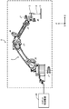
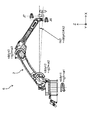
- FIG. 1 is a view showing the configuration of a vertical articulated six-axis robot.
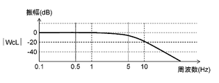
- FIG. 2A is a diagram showing a frequency response characteristic of the amplitude of the transfer function with respect to the operating frequency of the main axis.
- FIG. 2B is a diagram showing the frequency response characteristic of the phase of the transfer function with respect to the operating frequency of the main axis.
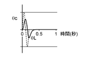
- FIG. 2C is a diagram showing time waveforms of the position command ⁇ c and the actual position ⁇ L when a 5 Hz sine wave is given as the position command ⁇ c to the main axis.
- FIG. 3 is a view showing the configuration of a vertical articulated seven-axis robot in which a movable axis is added to the tip of the vertical articulated six-axis robot.
- FIG. 3 is a view showing the configuration of a vertical articulated seven-axis robot in which a movable axis is added to the tip of the vertical articulated six-axis robot.
- FIG. 4 is a view showing a time change of a trajectory of a tip of a robot arm of the vertical articulated seven-axis robot shown in FIG.
- FIG. 5A is a diagram showing a frequency response characteristic of the amplitude of the transfer function with respect to the operating frequency of the end of the robot arm.
- FIG. 5B is a diagram showing frequency response characteristics of the phase of the transfer function with respect to the operating frequency of the tip of the robot arm.
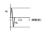
- FIG. 5C is a diagram showing time waveforms of the position command ⁇ c and the actual position ⁇ L when a 5 Hz sine wave is given as the position command ⁇ c to the tip of the robot arm.
- FIG. 5A is a diagram showing a frequency response characteristic of the amplitude of the transfer function with respect to the operating frequency of the end of the robot arm.
- FIG. 5B is a diagram showing frequency response characteristics of the phase of the transfer function with respect to the operating frequency of the tip of the robot arm.
- FIG. 5C is a diagram showing time wave
- FIG. 6 is a diagram showing a time change of the trajectory of the tip of the robot arm of the vertical articulated seven-axis robot when the reduction gear is bent.
- FIG. 7 is a schematic view for explaining the positional deviation of the tip of the robot arm caused by the external force torque.
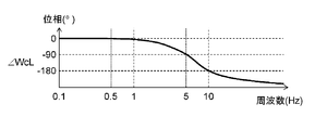
- FIG. 8A is a diagram showing a frequency response characteristic of the amplitude of the transfer function with respect to the operating frequency of the main shaft when the reduction gear is bent.
- FIG. 8B is a diagram showing the frequency response characteristic of the phase of the transfer function with respect to the operating frequency of the main shaft when the reduction gear is bent.
- FIG. 8C is a diagram showing time waveforms of the position command ⁇ c and the actual position ⁇ L when a sine wave of 0.5 Hz is given as the position command ⁇ c to the main axis.
- FIG. 8D is a diagram showing time waveforms of the position command ⁇ c and the actual position ⁇ L when a 5 Hz sine wave is given as the position command ⁇ c to the main axis.
- FIG. 9 is a functional block diagram related to position control of the vertical articulated seven-axis robot shown in FIG.
- FIG. 10 is a diagram for explaining the bending of the reduction gear in the robot mechanism.
- FIG. 11 is a block diagram of the load shown in FIG.
- FIG. 12 is a block diagram of a first servo control unit for comparison.
- FIG. 13 is a block diagram of the deflection correction block shown in FIG.
- FIG. 14 is a block diagram of a first servo control unit according to the first embodiment of the present disclosure.
- FIG. 15 is a block diagram of the deflection correction block shown in FIG.
- FIG. 16A is a diagram showing a frequency response characteristic of the amplitude of the transfer function with respect to the operating frequency of the main shaft according to the first embodiment.
- FIG. 16B is a diagram showing frequency response characteristics of the phase of the transfer function with respect to the operating frequency of the main shaft according to the first embodiment.
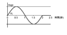
- FIG. 16C is a diagram showing time waveforms of the position command ⁇ c and the actual position ⁇ L when a sine wave of 0.5 Hz is given as the position command ⁇ c to the main axis.
- FIG. 16A is a diagram showing a frequency response characteristic of the amplitude of the transfer function with respect to the operating frequency of the main shaft according to the first embodiment.
- FIG. 16B is a diagram showing
- FIG. 16D is a diagram showing time waveforms of the position command ⁇ c and the actual position ⁇ L when a 5 Hz sine wave is given as the position command ⁇ c to the main axis.
- FIG. 17 is a block diagram of a first servo control unit according to a second embodiment of the present disclosure.
- FIG. 18 is a block diagram of the deflection correction block shown in FIG.
- the external force torque includes torque due to gravity and interference torque received from other joint axes.
- the present inventors have found that the influence on the position command after deflection correction, specifically, the response frequency is different between the gravity torque and the interference torque.
- the operation of the vertical articulated robot will be described as an example.
- FIG. 1 shows the configuration of a conventional vertical articulated robot used in laser welding and cutting.
- the vertical articulated six-axis robot 1 has a robot arm 2 and joint axes J1 to J6.
- the robot arm 2 is divided into a plurality of portions, and joint portions of the respective portions are provided with joint axes J1 to J6.
- the joint axes J1 to J6 respectively connect servomotors (not shown) via reduction gears (not shown).
- the robot control device 20 drives the servomotors according to the position command ⁇ c (see FIG. 10) to rotate the joint axes J1 to J6 by desired amounts, respectively, to control the movement and posture of the robot arm 2.
- a laser output device 3 is attached to the end of the robot arm 2.
- a laser light source (not shown) for generating a laser beam 4 and an optical fiber (not shown) for guiding the laser beam 4 are connected to the laser output device 3.
- the vertical articulated six-axis robot 1 has a total of six joint axes including three main axes J1 to J3 which determine the overall posture and three wrists J4 to J6 which determine the direction of the tip.
- the X, Y, and Z directions shown in FIG. 1 may be used to describe the position and movement of the vertical articulated six-axis robot 1.
- the laser output device 3 has, for example, a mass of about 5 kg.
- the posture of the robot arm 2 in the vertical articulated six-axis robot 1 having six axes, that is, the angle of each joint axis is uniquely determined. As described above, since the control redundancy of the joint axes is zero, all joint axes operate when cutting with a circular locus.
- each joint axis receives and operates a sinusoidal position command ⁇ c corresponding to the operating frequency.
- a frequency at which each joint axis can respond in response to the position command ⁇ c is defined as a position response frequency
- the position of each joint axis (hereinafter referred to as an actual position) is set as ⁇ L.
- the position command ⁇ c indicates an angle command that instructs the rotation angle amount of each joint axis
- the actual position ⁇ L indicates a rotation angle amount at which each joint axis actually rotates.
- the position response frequency is determined by the natural vibration frequency of each joint axis constituting the vertical articulated six-axis robot 1 and the characteristics of the control device (see FIG. 9) which drives each joint axis.
- a transfer function WcL until each joint axis reaches the actual position ⁇ L in response to the position command ⁇ c is defined by the following (formula 1).
- the position response frequency is the frequency at which the amplitude of the transfer function WcL is half (-6 dB) or the frequency at which the phase of the transfer function WcL is delayed by 90 °, whichever is lower.
- the position response frequency becomes minimum at an arm extension posture (inertia is maximum) and becomes about 5 Hz.
- FIGS. 2A and 2B show the response of the transfer function to the operating frequency of the main axis
- FIG. 2A shows the frequency response of the amplitude of the transfer function WcL
- FIG. 2B shows the frequency response of the phase of the transfer function WcL.
- FIG. 2C shows time waveforms of ⁇ c and ⁇ L when a 5 Hz sine wave is given as the position command ⁇ c to the main axis having the frequency characteristics shown in FIGS. 2A and 2B.
- the amplitude is half (-6 dB) and the phase is delayed by 90 °.
- the amplitude of the actual position ⁇ L is half of the position command ⁇ c, and the phase is delayed by 90 °.
- the wrist three axes J4 to J6 are smaller and lighter than the three main axes J1 to J3. Therefore, even if the laser output device 3 of about 5 kg is mounted, the three wrist axes J4 to J6 have a position response frequency of 10 Hz or more. Therefore, a new joint axis J7 may be added to the tip of the robot arm 2.
- the robot arm 2 is sufficient even at an operation frequency of 5 Hz or more by maintaining the stopped state of the main spindles 3 axes J1 to J3 and performing positioning and trajectory tracking operation with the wrist 3 axes J4 to J6 and the new joint axis J7. Position responsiveness can be realized. That is, the joint axes J1 to J5 are completely stopped so that the rotation center position 8 of the joint axis J6 does not move.
- FIG. 3 shows the configuration of a vertical articulated seven-axis robot in which a joint axis J7 parallel to the joint axis J6 at the tip is added.
- the vertical articulated seven-axis robot 6 can operate only the joint axes J6 and J7 of the tip portion to draw a desired trajectory such as a circle or an ellipse at the tip of the robot arm 2.
- FIG. 4 shows a time change of the trajectory of the end of the robot arm of the vertical articulated seven-axis robot 6 shown in FIG.
- the joint axes J1 to J5 of the robot arm 2 are driven to move the laser irradiation position 7 to the center of the target circular trajectory, and laser irradiation is started.
- the joint axes J6 and J7 are rotated in the respective rotational directions 9 and 10 so that the laser irradiation position 7 is moved in the + Y direction and put on the circular orbit.
- the joint axes J6 and J7 are rotated so that the laser irradiation position 7 moves along the circular orbit from time t3 to t5, and the laser irradiation is ended at time t6.
- FIGS. 5A and 5B show the response characteristic of the transfer function to the operating frequency at the end of the robot arm.
- FIG. 5A shows the frequency response characteristic of the amplitude of the transfer function WcL
- FIG. 5B shows the frequency response characteristic of the phase of the transfer function WcL.
- the tip of the robot arm indicates joint axes J6 and J7.
- 5C shows time waveforms of ⁇ c and ⁇ L when a 5 Hz sine wave is given as the position command ⁇ c to the robot arm having the frequency characteristics shown in FIGS. 5A and 5B.
- the position response frequency is higher than that of the main axis, for example, about 20 Hz.
- FIGS. 5A and 5B when the position response frequency is 20 Hz, the amplitude is halved (-6 dB) and the phase is delayed by 90 °.
- FIG. 5C when the frequency of the position command ⁇ c is 5 hz, the attenuation of the amplitude and the delay of the phase are small in the actual position ⁇ L, and the actual position ⁇ L is better for the position command ⁇ c than in the case shown in FIG. It is understood that it is following.
- the tip of the robot arm 2 can draw a circular locus substantially as instructed.
- the inventors of the present invention actually investigated the swing of the rotation center position 8 of the joint axis J6 in the operation of laser cutting a circle with a diameter of 10 mm at 10 m / min. From this investigation, it was found that a shake of about 1 mm was generated on the joint axis J6, and an error of about 10% was given to the locus drawn by the tip of the robot arm 2. Further, in the vertical articulated seven-axis robot 6 shown in FIG. 3, the characteristics of the reduction gear also differ for each joint axis. Therefore, the amount of deflection generated in each reduction gear is also different, and the swinging direction of the rotation center position 8 of the joint axis J6 also becomes distorted.
- FIG. 6 shows the time change of the trajectory of the tip of the robot arm of the vertical articulated seven-axis robot 6 when the reduction gear is bent.
- the joint axes J1 to J5 of the robot arm 2 are driven to move the laser irradiation position 7 to the center of the target circular trajectory, and laser irradiation is started.
- the laser irradiation position 7 is moved in the + Y direction at time t2, and the joint axes J6 and J7 are rotated so as to place the tip of the robot arm 2 on a circular path.
- the reduction gear of the joint axis J1 mainly bends, and the rotation center position 8 of the joint axis J6 shifts in the + Y direction.
- the laser irradiation position 7 is moved in the + X direction along the circular path, so the reduction gear of the joint axis J2 mainly bends due to the interference torque, and the rotation center position 8 of the joint axis J6 shifts in the + X direction.
- the amount of deviation of the rotation center position 8 of the joint axis J6 in the + X direction is about half the amount of deviation in the + Y direction.
- positional deviation of the rotation center position 8 of the joint axis J6 occurs due to the influence of the interference torque.
- the position command ⁇ c is a circular locus
- the locus of the actual position ⁇ L is an elliptical locus which is slightly expanded from the circular locus.
- an error may occur in which the diameter of the circular locus decreases by about 50%.
- the error of the locus of the actual position ⁇ L is small compared to this error, it generally exceeds the allowable error when processing is performed using a robot, so some measures need to be taken.
- FIG. 7 is a schematic view for explaining the positional deviation of the tip of the robot arm caused by the external force torque.
- the external force torques .tau.ddyn1, .tau.ddyn2, and .tau.ddyn3 applied to the three main axes J1 to J3 are respectively the sum of the gravity torque and the interference torque, that is, (.tau.g1 + .tau.a1), (.tau.g2 + .tau.a2), (.tau.g3 + .tau.a3).
- FIG. 7 shows only the deflection amount ⁇ s2 of the joint axis J2.
- a deflection correction value ⁇ sc (hereinafter referred to as a position command correction value) to be added to the position command ⁇ c is expressed by the following equation (2), where Ks is a spring constant of the reduction gear.
- ⁇ s is a deflection amount generated between the primary side and the secondary side of a reduction gear described later.
- a deflection correction value ⁇ sgc (hereinafter, referred to as a first position command correction value) based on the gravity torque ⁇ g and a deflection correction value ⁇ sac based on the interference torque ⁇ a are respectively expressed by the following equations (3) and (4).
- the frequency of the gravity torque ⁇ g is 0 Hz.
- the robot's 3 spindles J1 to J3 with an arm length of 2 m and a payload of about 10 kg have an operating angular velocity of about 180 ° / sec and only rotates about a half turn in 1 second. Even during operation, the change of the gravity torque ⁇ g is less than 0.5 Hz. Therefore, the vibration frequency of the robot arm 2 due to the gravity torque ⁇ g is also less than 0.5 Hz. Even if the position response frequency of the main spindles 3 axes J1 to J3 is about 5 Hz, it can sufficiently follow and deflection correction becomes possible.
- the deflection due to the interference torque ⁇ a is not sufficiently corrected even if the deflection correction value ⁇ sac due to the interference torque ⁇ a is added to the position command ⁇ c.
- the reason is as follows.
- the central frequency of deflection of the robot arm 2 due to the interference torque ⁇ a is 5 Hz. Therefore, as shown in (Expression 4), the frequency of the deflection correction value ⁇ sac due to the interference torque ⁇ a is also 5 Hz.
- FIG. 8A and 8B show the response characteristic of the transfer function with respect to the operating frequency of the main shaft when the reduction gear is bent
- FIG. 8A shows the frequency response characteristic of the amplitude of the above transfer function WcL
- FIG. 8B shows the transfer function WcL
- the frequency response characteristics of the phase of are respectively shown.
- FIG. 8C shows the time waveforms of ⁇ c and ⁇ L when a sine wave of 0.5 Hz is given as the position command ⁇ c to the main axis having the frequency characteristics shown in FIGS. 2A and 2B
- FIG. 8D shows the position command ⁇ c.
- the time waveform of (theta) c and (theta) L at the time of giving a 5 Hz sine wave is shown.
- the actual position ⁇ L sufficiently follows the first position command correction value ⁇ sgc.
- the frequency of the first position command correction value ⁇ sgc is 0.5 Hz.
- FIG. 8D it can be seen that the actual position ⁇ L is half in amplitude and 90 ° behind the phase with respect to the deflection correction value ⁇ sac due to the interference torque ⁇ a.
- the external force torque ⁇ ddyn is integrally calculated without being separated into the gravity torque and the interference torque, and the position command correction value ⁇ sc is obtained based on this value. Therefore, for example, when the position command correction value ⁇ sc is increased in response to the decrease of the actual correction amplitude of the deflection due to the interference torque ⁇ a, the first position command correction value ⁇ sgc by the gravity torque ⁇ g is also increased. As a result, a problem occurs in which the arm is pulled up more than the amount of deflection due to gravity.
- the inventors of the present application can operate the robot arm 2 with a desired trajectory by dividing the external force torque into the gravitational torque and the interference torque and correcting the positional deviation of the robot arm 2 based on these results. Found out. This is discussed in more detail below.
- FIG. 9 is a functional block diagram related to position control of the vertical articulated seven-axis robot 6 shown in FIG. 3, and shows an outline of the internal configuration of the robot mechanism and the robot control device.
- the robot mechanism 11 is a mechanical drive unit of the vertical articulated seven-axis robot 6 and includes servomotors 12, 12... (Hereinafter simply referred to as motors), speed reducers 13, 13. ⁇ ⁇ And have. Although not shown, the robot mechanism 11 includes the robot arm 2.
- the motor 12 is connected to joint axes J1 to J7 of the vertical articulated seven-axis robot 6 shown in FIG.
- the motor 12 drives the joint axes J1 to J7 in accordance with a control signal sent from the servo control unit 23 of the robot control device 20, and controls the movement and the attitude of the robot arm 2.
- the encoder 14 is connected to the motor 12, detects the amount of rotation and the rotation speed, and sends a detection signal as a feedback signal to the servo control unit 23.
- the motor 12, the reduction gear 13 and the encoder 14 connected to the joint axis J1 will be referred to as the "first motor”, the “first reduction gear” and the “first encoder”, respectively.
- motors connected to the joint axes J2 to J7 may be referred to as “second to seventh motors” or the like.
- the servo control unit 23 and the deflection correction block 24 connected to the first motor may be referred to as a “first servo control unit” and a “first deflection correction block”, respectively.
- position command or position command correction value sent to each joint axis may be referred to as position command ⁇ c to ⁇ 7c or position command correction value ⁇ sc to ⁇ 7sc.
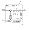
- the robot control device 20 has an operation / teaching unit 21, a main control unit 22, a servo control unit 23, and a deflection correction block 24 (a deflection correction unit).
- the operation / teaching unit 21 stores, for example, the trajectory of the robot arm 2 acquired at the time of teaching, the rotational operation of each of the motors 12, 12... For drawing the trajectory, and the like.
- the main control unit 22 receives the instruction from the operation / teaching unit 21 and follows the movement trajectory of the robot arm 2 etc. of the robot mechanism 11 stored in the operation / teaching unit 21.
- the position commands ⁇ c to ⁇ 7c of the axes J1 to J7 are output, respectively.
- the first to seventh servo control units 23, 23 ... follow the position commands ⁇ c to ⁇ 7c sent from the main control unit 22, and the first to seventh motors 12 in the robot mechanism 11 Control the rotation of 12.
- the deflection correction blocks 24, 24... are provided between the main control unit 22 and the servo control units 23, 23,... In correspondence with the joint axes J1 to J7.
- the deflection correction blocks 24, 24,... Generate position command correction values ⁇ sc to ⁇ 7sc based on the position commands ⁇ c to ⁇ 7c received from the main control unit 22.
- the generated position command correction values ⁇ sc to ⁇ 7sc are added to the corresponding position commands ⁇ c to ⁇ 7c, and sent to the first to seventh servo control units 23, 23,.
- Each functional block in the robot control device 20 may be configured by an independent circuit or may be configured by one integrated circuit. A combination of some functional blocks may be configured in one integrated circuit.
- the functions of the main control unit 22, the servo control unit 23, and the deflection correction block 24 are substantially realized by executing a program described in software on an integrated circuit such as a CPU.
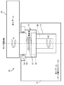
- FIG. 10 shows a diagram for explaining the deflection of the reduction gear in the robot mechanism.
- the motor 12 and the reduction gear 13 and a part of the robot arm 2 connected to them are extracted as the load 30 from the robot mechanism 11.
- the load 30 includes a first arm 31 serving as a motor mounting base, a motor 12 connected thereto, and a reduction gear secondary side 33 having a reduction gear primary side 32 and a bearing 34 connected to the motor 12
- a reduction gear 13 and a second arm 35 rotatably connected to the reduction gear secondary side 33 are included.
- the reduction gear primary side 32 is coupled to the rotor 36 of the motor 12 via the rotation shaft of the motor 12 and rotates by the motor rotation position ⁇ M sent from the servo control unit 23.
- the reduction gear 13 converts the motor rotational position ⁇ M into an arm rotational position (actual position) ⁇ L at a reduction ratio Rg shown in (Expression 6).
- the reduction gear 13 has a spring component 37 between the reduction gear primary side 32 and the reduction gear secondary side 33. It is only a steady state in which the elongation, that is, the deflection becomes constant.
- FIG. 11 shows a block diagram of the load shown in FIG. 10, where IM is a motor current command for driving the motor 12, Kt is a torque constant of the motor 12, 1 / Rg is an inverse number of the reduction ratio shown in (Expression 6) Ks is a spring constant of the reduction gear 13, ⁇ s is a deflection amount generated between the reduction gear primary side 32 and the reduction gear secondary side 33, and ⁇ ddyn is an external force torque applied to the robot arm 2.
- IM motor current command for driving the motor 12
- Kt is a torque constant of the motor 12
- 1 / Rg is an inverse number of the reduction ratio shown in (Expression 6)
- Ks is a spring constant of the reduction gear 13
- ⁇ s is a deflection amount generated between the reduction gear primary side 32 and the reduction gear secondary side 33
- ⁇ ddyn is an external force torque applied to the robot arm 2.
- a current determined by the motor current command IM flows in the motor 12.
- JM is the moment of inertia about the rotation axis obtained by combining the rotor 36 of the motor 12 and the reduction gear primary side 32
- DM is the coefficient of viscous friction
- JL is the moment of inertia about the rotation axis obtained by combining the second arm 35 and the reduction gear secondary side 33
- DL is the coefficient of viscous friction.
- the motor rotational position ⁇ M is obtained based on the motor current command IM.
- the first value is obtained by multiplying the motor rotational position ⁇ M by the reciprocal 1 / Rg of the reduction ratio.
- the arm rotational position ⁇ L is obtained based on the external force torque ⁇ ddyn.
- the arm rotational position ⁇ L is subtracted from the first value to calculate the amount of deflection ⁇ s generated between the reduction gear primary side 32 and the reduction gear secondary side 33.
- the obtained deflection amount ⁇ s is multiplied by the spring constant Ks to obtain a second value.
- the second value is added to the external force torque ⁇ ddyn.
- the second value is multiplied by the reciprocal 1 / Rg of the reduction ratio to obtain a third value.
- a third value is subtracted from the product of the motor current command IM and the torque constant Kt of the motor 12.
- FIG. 11 is a general control block diagram of a motor in which a load and a reduction gear are connected, so detailed description of functions other than the above is omitted.
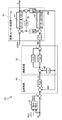
- FIG. 12 shows a block diagram of a first servo control unit for comparison.
- Position control block 50 of servo control unit 23 receives a fourth value obtained by adding position command ⁇ c and deflection correction value ⁇ sco (also referred to as position command correction value ⁇ sco) output from deflection correction block 24.
- the fifth value is obtained by subtracting the motor rotational position ⁇ M from the fourth value.
- the fifth value is multiplied by the position proportional gain Kpp to generate the speed command ⁇ c.
- the motor rotational position ⁇ M is obtained from the detection signal of the first encoder 14 which is a position detector.
- the motor rotational position ⁇ M is differentiated to obtain the motor speed ⁇ M.
- the motor speed ⁇ M is subtracted from the speed command ⁇ c to obtain a sixth value.
- the sixth value is multiplied by the speed proportional gain Kps to obtain a seventh value.
- the sixth value is integrated and multiplied by the velocity integral gain Ki to obtain an eighth value.
- the seventh value and the eighth value are added to calculate the current supplied to the first motor 12 to obtain the motor current command IM.
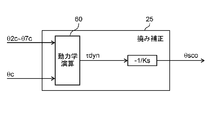
- FIG. 13 shows a detailed configuration of the deflection correction block shown in FIG.
- the deflection correction block 25 has a dynamics calculation block 60.
- (Equation 2) in order to obtain the position command correction value ⁇ sco, it is necessary to obtain the external force torque ⁇ ddyn in advance, but it is necessary to attach a torque sensor to each joint axis and obtain this from the aspect of cost Unfavorable to see. This is because torque sensors are generally expensive. Also, by attaching a torque sensor to each joint shaft, an extra deflection is added to the robot arm 2.
- the dynamics calculation block 60 obtains the external force torque calculation value ⁇ dyn.
- the dynamics operation block 60 performs a dynamics operation using the position commands ⁇ c to ⁇ 7c of all the axes, the velocity components which are their differential values, and the acceleration components which are their second order differential values, and The external force torque is calculated.
- the external-command torque calculated value ⁇ dyn is multiplied by the reciprocal of the spring constant Ks and the sign-reversed sign to obtain a position command correction value ⁇ sco.
- the external force torque calculation value ⁇ dyn includes both the gravitational torque ⁇ g and the interference torque ⁇ a. Therefore, the actual correction amplitude of the deflection due to the high frequency interference torque ⁇ a decreases.
- the position command correction value ⁇ sco is increased, the position command correction value by the gravity torque ⁇ g is also increased. As described above, this causes the problem that the arm is pulled up more than the amount of deflection due to gravity and sinking.
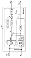
- FIG. 14 shows a block diagram of a first servo control unit according to the present embodiment, and in this first servo control unit 23, the functional blocks excluding the deflection correction block 24 are the same as the configuration shown in FIG. So I will omit the explanation.
- FIG. 15 shows a detailed configuration of the deflection correction block 24 shown in FIG.
- the deflection correction block 24 (deflection correction means) has a dynamics calculation block 61 and a gravity calculation block 62.
- the dynamics operation block 61 obtains an external force torque operation value ⁇ dyn using position commands ⁇ c to ⁇ 7c sent from the main control unit 22 for all axes.
- the calculation of the external force torque applied to each joint axis in the dynamics calculation block 61 is the same as the above-described method illustrated for comparison. That is, when the number of joint axes is n (n is an integer of 2 or more), one deflection correction block 24 corresponds to n servomotors 12, 12 ... sent from the main control unit 22. The n position commands ⁇ c to ⁇ nc are received, and based on these position commands, the positional deviation of the robot arm 2 due to the deflection of the reduction gear 13 is corrected.
- the gravity torque ⁇ g and the interference torque ⁇ a are separated in the deflection correction block 24, and the position command correction value for each is calculated.
- the gravity calculation block 62 receives the position commands ⁇ c to ⁇ 7c in the same manner as the dynamics calculation block 61.
- the gravity calculation block 62 calculates the gravity torque ⁇ g by performing the dynamics calculation with the above-mentioned velocity component and acceleration component as zero.
- any of the external force torque calculation value ⁇ dyn, the gravity torque ⁇ g, and the interference torque ⁇ a can be obtained by calculation in the deflection correction block 24.
- the first position command correction value ⁇ sgc is obtained from (Expression 9) using the obtained gravity torque ⁇ g.
- Kpa a PD compensation proportional gain, which is a coefficient for amplitude compensation.
- Kda a PD compensation differential gain, which is a coefficient for phase compensation.
- s is an integral element.
- the position command correction value ⁇ sc is obtained from the values calculated by (Equation 9) and (Equation 11).
- the gravity calculation block 62 and the calculation function shown in Equation 9 in the deflection correction block 24 will be collectively referred to as a first position command correction value calculation means 63. Also, the second position command correction value calculation is performed by combining the calculation functions shown in (Equation 8), (Equation 10) and (Equation 11) in the dynamics calculation block 61, the gravity calculation block 62, and the deflection correction block 24. It will be called means 64.
- a new position command ( ⁇ c + ⁇ sc) in which the position command correction value ⁇ sc represented by (Expression 12) is added to the position command ⁇ c sent from the main control unit 22 to the first servo control unit 23 is The first servo control unit 23 is input.
- the first servo control unit 23 controls the drive of the first motor 12 by a new position command.
- FIG. 16A and 16B show the response characteristic of the transfer function to the operating frequency of the main shaft according to this embodiment
- FIG. 16A shows the frequency response characteristic of the amplitude of the transfer function WcL
- FIG. 16B shows the frequency response characteristic of the phase of the transfer function WcL.
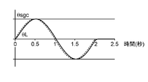
- FIG. 16C shows the time of the first position command correction value ⁇ sgc and the actual position ⁇ L when a sine wave of 0.5 Hz is given as the first position command correction value ⁇ sgc to the main axis having the frequency characteristics shown in FIGS. 16A and 16B.
- FIG. 16D shows waveforms
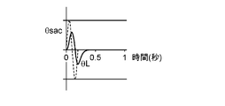
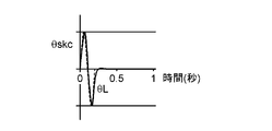
- FIG. 16D shows time waveforms of the second position command correction value ⁇ skc and the actual position ⁇ L when a 5 Hz sine wave is given as the second position command correction value ⁇ skc.
- the actual position ⁇ L sufficiently follows the first position command correction value ⁇ sgc.
- the frequency of the first position command correction value ⁇ sgc is 0.5 Hz which is the maximum value of the vibration frequency of the robot arm 2 due to the gravity torque ⁇ g.
- the actual position ⁇ L sufficiently follows both the amplitude and the phase with respect to the second position command correction value ⁇ skc having a frequency of 5 Hz.
- the gravity torque ⁇ g and the interference torque ⁇ a are separately calculated and calculated.
- First and second position command correction values ⁇ sgc and ⁇ skc are obtained based on the torque. By this, it is possible to correct the position command without excessively estimating the influence of the deflection due to the gravity torque ⁇ g. Also, by adding these position command correction values ⁇ sgc and ⁇ skc to the original position command ⁇ c, it is possible to correct the positional deviation of the robot arm 2 with high accuracy.
- each deflection correction block 24 receives seven position commands ⁇ c to ⁇ 7c sent from the main control unit 22 to the seven servo control units 23, 23.
- the individual deflection correction block 24 calculates the external force torque operation value ⁇ dyn and the gravity torque ⁇ g by kinetic operation based on these position commands ⁇ c to ⁇ 7c. Therefore, it is not necessary to provide a dedicated part for measuring torque, such as a torque sensor, and the cost of the vertical articulated six-axis robot 6 and the robot control device 20 can be reduced.
- the interference torque ⁇ a is obtained by subtracting the gravity torque ⁇ g from the external force torque calculation value ⁇ dyn. Therefore, the gravitational torque ⁇ g and the interference torque ⁇ a can be easily separated, and the positional deviation of the robot arm 2 due to the bending can be corrected.
- position teaching of a robot is increasingly performed off-line using a GUI such as a personal computer instead of teaching playback.
- teaching / playback there is no problem as long as the repeat accuracy is high even if the tip position of the robot arm 2 instructed to the motors 12, 12... And the tip position of the actual robot arm 2 deviate.
- the off-line teaching requires an absolute position accuracy, if the above-mentioned deflection correction is not correctly performed, it becomes a problem in controlling the robot.
- the positional deviation of the robot arm 2 due to the bending can be accurately corrected, and off-line teaching can be smoothly performed.
- FIG. 17 is a block diagram of a first servo control unit according to the present embodiment.
- the difference between the configuration shown in the present embodiment and the configuration shown in the first embodiment is the following three points.
- One is to obtain an interference torque current compensation value Isc (hereinafter simply referred to as a current compensation value) in the deflection correction block 26 based on the interference torque ⁇ a.
- the second is to add the current compensation value Isc to the motor current command IM.
- the third is that only the first position command correction value ⁇ sgc is added to the position command ⁇ c.
- FIG. 18 shows a detailed configuration of the deflection correction block shown in FIG.
- the gravity torque ⁇ g is calculated by the gravity calculation block 62, and the interference torque ⁇ a is calculated by (Expression 7), as in the first embodiment.
- the position command correction value ⁇ sc shown in (Expression 12) is corrected as shown in (Expression 13).
- the deflection correction value ⁇ sac ⁇ sgc (Equation 13)
- the deflection correction value ⁇ sac is not determined from the interference torque ⁇ a, but a current corresponding to the deflection correction value ⁇ sac is determined.
- the compensation of the amplitude and the phase is also required for the current, and the current compensation value Isc is represented by the following (Expression 14).
- Kpb is an interference torque current compensation proportional gain, which is a coefficient for amplitude compensation.
- Kdb is an interference torque current compensation differential gain and is a coefficient for phase compensation.
- Other calculation elements are as described above.
- the motor current command IMb output from the speed control block 52 is represented by the following (Equation 15) based on the value calculated by (Equation 14).
- the new position command is input to the position control block 50 of the first servo control unit 23.
- the current compensation value Isc is added to the motor current command IM generated in the position control block 50 and the speed control block 51 to obtain a new motor current command IMb.
- the drive of the first motor 12 is controlled based on the new position command ( ⁇ c + ⁇ sgc) and the new motor current command IMb.
- the deflection of the motor current is corrected directly based on the interference torque ⁇ a by adding the current compensation value Isc due to the interference torque ⁇ a to the motor current command IM.
- the response of the load 30 can be enhanced. That is, the correction effect of the deflection due to the interference torque ⁇ a can be improved.
- deflection due to the interference torque ⁇ a is generated within the position control block 50 and the speed control block 52 instead of the position commands ⁇ c to ⁇ 7c sent from the outside of the position control block 50 or the speed control block 52.
- the correction is added to the motor current command IM. That is, since the deflection is indirectly compensated, the whole of the current compensation value Isc added to the motor current command IM does not necessarily contribute to the decrease in deflection. Therefore, in order to accurately determine the current compensation value Isc, it may be necessary to repeat the operation check on the actual device and the adjustment of the gain and the like.
- the vertical articulated seven-axis robot 6 has been described as an example, but the present invention is not particularly limited thereto.
- the number of joint axes of the robot is not limited to seven, and may be appropriately changed according to the specification of the robot.
- the robot controller 20 has n (n is an integer of 2 or more) servo controllers 23, 23... Corresponding n servo motors 12, 12. While driving, n joint shafts are driven via reduction gears 13, 13... Respectively connected to n servo motors 12, 12.
- the deflection correction blocks 24 and 26 receive n position commands ⁇ c to ⁇ nc sent from the main control unit 22 to the n servo control units 23, 23. It is comprised so that the position shift of the robot arm 2 by bending may be correct
- the robot control device can separate the deflection due to the gravity torque and the deflection due to the interference torque from the other axes, and correct the position command for each, so that the positional deviation of the robot arm can be reduced. It is useful when applied to industrial robots such as welding robots.
Landscapes
- Engineering & Computer Science (AREA)
- Robotics (AREA)
- Mechanical Engineering (AREA)
- Manipulator (AREA)
- Numerical Control (AREA)
Abstract
L'invention concerne un dispositif de commande de robot comprenant : une unité de commande principale ; une unité de servocommande qui reçoit une instruction de position (θc) de l'unité de commande principale ; et un bloc de correction de déviation (24) qui corrige une déviation d'un engrenage réducteur raccordé à un servomoteur. Le bloc de correction de déviation (24) comprend : un premier moyen de calcul de valeur de correction de position (63) qui obtient une première valeur de correction d'instruction de position (θsgc) sur la base de l'instruction de position (θc) ; et un second moyen de calcul de valeur de correction d'instruction de position (64) qui obtient une seconde valeur de correction d'instruction de position (θskc) sur la base d'un couple d'interférence (τa). L'unité de servocommande entraîne le servomoteur sur la base d'une nouvelle instruction de position obtenue en ajoutant la première valeur de correction d'instruction de position (θsgc) et la seconde valeur de correction d'instruction de position (θskc) à l'instruction de position (θc).
Priority Applications (4)
| Application Number | Priority Date | Filing Date | Title |
|---|---|---|---|
| JP2019529020A JP6998514B2 (ja) | 2017-07-11 | 2018-06-21 | ロボット制御装置 |
| CN201880045677.3A CN110869171B (zh) | 2017-07-11 | 2018-06-21 | 机器人控制装置 |
| EP18832600.3A EP3653347B1 (fr) | 2017-07-11 | 2018-06-21 | Dispositif de commande de robot |
| US16/726,302 US11613013B2 (en) | 2017-07-11 | 2019-12-24 | Robot control device |
Applications Claiming Priority (2)
| Application Number | Priority Date | Filing Date | Title |
|---|---|---|---|
| JP2017135620 | 2017-07-11 | ||
| JP2017-135620 | 2017-07-11 |
Related Child Applications (1)
| Application Number | Title | Priority Date | Filing Date |
|---|---|---|---|
| US16/726,302 Continuation US11613013B2 (en) | 2017-07-11 | 2019-12-24 | Robot control device |
Publications (1)
| Publication Number | Publication Date |
|---|---|
| WO2019012942A1 true WO2019012942A1 (fr) | 2019-01-17 |
Family
ID=65001988
Family Applications (1)
| Application Number | Title | Priority Date | Filing Date |
|---|---|---|---|
| PCT/JP2018/023611 Ceased WO2019012942A1 (fr) | 2017-07-11 | 2018-06-21 | Dispositif de commande de robot |
Country Status (5)
| Country | Link |
|---|---|
| US (1) | US11613013B2 (fr) |
| EP (1) | EP3653347B1 (fr) |
| JP (1) | JP6998514B2 (fr) |
| CN (1) | CN110869171B (fr) |
| WO (1) | WO2019012942A1 (fr) |
Cited By (3)
| Publication number | Priority date | Publication date | Assignee | Title |
|---|---|---|---|---|
| CN115139296A (zh) * | 2021-03-31 | 2022-10-04 | 精工爱普生株式会社 | 机器人的控制方法、机器人系统以及存储介质 |
| DE112021002634T5 (de) | 2020-07-31 | 2023-03-23 | Fanuc Corporation | Steuervorrichtung und Robotersystem |
| US12280504B2 (en) | 2019-11-05 | 2025-04-22 | Panasonic Intellectual Property Management Co., Ltd. | Robot control method |
Families Citing this family (1)
| Publication number | Priority date | Publication date | Assignee | Title |
|---|---|---|---|---|
| JP7234577B2 (ja) * | 2018-10-31 | 2023-03-08 | セイコーエプソン株式会社 | ロボットシステム、ロボット制御方法、及びエンコーダー |
Citations (7)
| Publication number | Priority date | Publication date | Assignee | Title |
|---|---|---|---|---|
| JPS493765B1 (fr) | 1969-10-22 | 1974-01-28 | ||
| JPH08118275A (ja) * | 1994-10-19 | 1996-05-14 | Toyota Central Res & Dev Lab Inc | マニピュレータの制御装置 |
| JPH08118270A (ja) * | 1994-10-25 | 1996-05-14 | Yaskawa Electric Corp | 産業用ロボットの制御方法とその装置 |
| JP2002307344A (ja) * | 2001-04-16 | 2002-10-23 | Fanuc Ltd | ロボット制御装置 |
| JP2003530230A (ja) * | 2000-04-10 | 2003-10-14 | エービービー エービー | 産業ロボットの経路補正 |
| WO2005009692A1 (fr) * | 2003-07-29 | 2005-02-03 | Matsushita Electric Industrial Co., Ltd. | Procede de commande du bras d'un robot et dispositif de commande associe |
| JP2005052913A (ja) * | 2003-07-31 | 2005-03-03 | Nachi Fujikoshi Corp | ロボット制御装置 |
Family Cites Families (16)
| Publication number | Priority date | Publication date | Assignee | Title |
|---|---|---|---|---|
| US4933864A (en) * | 1988-10-04 | 1990-06-12 | Transitions Research Corporation | Mobile robot navigation employing ceiling light fixtures |
| JP2771458B2 (ja) * | 1994-07-19 | 1998-07-02 | 株式会社不二越 | 産業用ロボットの撓み補正方法 |
| JP3558179B2 (ja) * | 1995-06-01 | 2004-08-25 | ソニー株式会社 | サーボ制御装置及びサーボ制御方法並びにこれらを用いたロボット制御装置及びロボット制御方法 |
| JP3981773B2 (ja) | 1997-05-28 | 2007-09-26 | 株式会社安川電機 | ロボット制御装置 |
| US7845560B2 (en) * | 2004-12-14 | 2010-12-07 | Sky-Trax Incorporated | Method and apparatus for determining position and rotational orientation of an object |
| JP5277946B2 (ja) * | 2008-12-24 | 2013-08-28 | 株式会社安川電機 | ロボット制御装置およびロボットシステム |
| JP2011212823A (ja) * | 2010-04-02 | 2011-10-27 | Yaskawa Electric Corp | ロボットアーム位置補正パラメータの同定装置及び方法、並びにそれを用いたロボットコントローラ及びロボット制御方法 |
| JP5374613B2 (ja) * | 2012-05-30 | 2013-12-25 | 株式会社神戸製鋼所 | 多関節ロボットの弾性変形補償制御装置および制御方法 |
| JP5409844B2 (ja) | 2012-05-30 | 2014-02-05 | 株式会社神戸製鋼所 | 多関節ロボットの軌跡制御装置および制御方法 |
| US9434073B2 (en) * | 2012-08-02 | 2016-09-06 | Toshiba Kikai Kabushiki Kaisha | Robot apparatus and control method therefor |
| KR102668586B1 (ko) * | 2012-08-03 | 2024-05-28 | 스트리커 코포레이션 | 로봇 수술을 위한 시스템 및 방법 |
| JP2014033535A (ja) * | 2012-08-03 | 2014-02-20 | Kayaba Ind Co Ltd | モータ制御装置 |
| US9042487B2 (en) * | 2012-08-13 | 2015-05-26 | Texas Instruments Incorporated | Blind I/Q mismatch compensation with receiver non-linearity |
| US9744670B2 (en) * | 2014-11-26 | 2017-08-29 | Irobot Corporation | Systems and methods for use of optical odometry sensors in a mobile robot |
| JP6739954B2 (ja) * | 2016-03-18 | 2020-08-12 | キヤノン株式会社 | ロボット装置、物品の製造方法、および制御方法 |
| EP3443749B1 (fr) * | 2016-05-06 | 2021-09-15 | SZ DJI Technology Co., Ltd. | Systèmes et procédés d'affichage et de traitement de vidéo |
-
2018
- 2018-06-21 WO PCT/JP2018/023611 patent/WO2019012942A1/fr not_active Ceased
- 2018-06-21 EP EP18832600.3A patent/EP3653347B1/fr active Active
- 2018-06-21 JP JP2019529020A patent/JP6998514B2/ja active Active
- 2018-06-21 CN CN201880045677.3A patent/CN110869171B/zh active Active
-
2019
- 2019-12-24 US US16/726,302 patent/US11613013B2/en active Active
Patent Citations (7)
| Publication number | Priority date | Publication date | Assignee | Title |
|---|---|---|---|---|
| JPS493765B1 (fr) | 1969-10-22 | 1974-01-28 | ||
| JPH08118275A (ja) * | 1994-10-19 | 1996-05-14 | Toyota Central Res & Dev Lab Inc | マニピュレータの制御装置 |
| JPH08118270A (ja) * | 1994-10-25 | 1996-05-14 | Yaskawa Electric Corp | 産業用ロボットの制御方法とその装置 |
| JP2003530230A (ja) * | 2000-04-10 | 2003-10-14 | エービービー エービー | 産業ロボットの経路補正 |
| JP2002307344A (ja) * | 2001-04-16 | 2002-10-23 | Fanuc Ltd | ロボット制御装置 |
| WO2005009692A1 (fr) * | 2003-07-29 | 2005-02-03 | Matsushita Electric Industrial Co., Ltd. | Procede de commande du bras d'un robot et dispositif de commande associe |
| JP2005052913A (ja) * | 2003-07-31 | 2005-03-03 | Nachi Fujikoshi Corp | ロボット制御装置 |
Non-Patent Citations (1)
| Title |
|---|
| See also references of EP3653347A4 |
Cited By (4)
| Publication number | Priority date | Publication date | Assignee | Title |
|---|---|---|---|---|
| US12280504B2 (en) | 2019-11-05 | 2025-04-22 | Panasonic Intellectual Property Management Co., Ltd. | Robot control method |
| DE112021002634T5 (de) | 2020-07-31 | 2023-03-23 | Fanuc Corporation | Steuervorrichtung und Robotersystem |
| DE112021002634B4 (de) * | 2020-07-31 | 2025-05-15 | Fanuc Corporation | Steuervorrichtung und Robotersystem |
| CN115139296A (zh) * | 2021-03-31 | 2022-10-04 | 精工爱普生株式会社 | 机器人的控制方法、机器人系统以及存储介质 |
Also Published As
| Publication number | Publication date |
|---|---|
| EP3653347A1 (fr) | 2020-05-20 |
| JP6998514B2 (ja) | 2022-01-18 |
| CN110869171B (zh) | 2023-03-10 |
| EP3653347B1 (fr) | 2024-09-11 |
| CN110869171A (zh) | 2020-03-06 |
| JPWO2019012942A1 (ja) | 2020-05-07 |
| US20200130181A1 (en) | 2020-04-30 |
| US11613013B2 (en) | 2023-03-28 |
| EP3653347A4 (fr) | 2020-08-12 |
Similar Documents
| Publication | Publication Date | Title |
|---|---|---|
| JP5897644B2 (ja) | ロボットの制御装置 | |
| KR101612218B1 (ko) | 다관절 로봇의 탄성 변형 보상 제어 장치 및 제어 방법 | |
| US20190337153A1 (en) | Robot | |
| CN104736303B (zh) | 多关节机器人的摆动控制装置 | |
| WO2018235812A1 (fr) | Système de robot et procédé de commande d'un système de robot | |
| JP6575200B2 (ja) | ロボット、制御装置およびロボットシステム | |
| JP6998514B2 (ja) | ロボット制御装置 | |
| JP2014028407A (ja) | ロボットの制御装置、制御方法、およびロボット | |
| JP2011101938A (ja) | ロボットおよびその制御装置 | |
| JP2017209762A (ja) | ロボット装置、ロボット制御方法、プログラム、記録媒体及び物品の製造方法 | |
| JP6934640B2 (ja) | ロボットの制御方法 | |
| JP7194910B2 (ja) | ロボット制御方法及びロボット制御装置 | |
| JP7349605B2 (ja) | ロボットの制御方法 | |
| JP6252272B2 (ja) | 垂直多関節型ロボットの位置誤差抑制方法 | |
| JP5633268B2 (ja) | ロボットの制御装置 | |
| JP7082365B2 (ja) | パラレルリンクロボット | |
| US12145275B2 (en) | Robot control method and robot control device | |
| JP6915470B2 (ja) | ロボットの制御装置 | |
| JP7414426B2 (ja) | ロボットシステム | |
| JP6926882B2 (ja) | ロボットの制御装置 | |
| WO2026074901A1 (fr) | Dispositif de commande de robot et procédé de commande de robot |
Legal Events
| Date | Code | Title | Description |
|---|---|---|---|
| 121 | Ep: the epo has been informed by wipo that ep was designated in this application |
Ref document number: 18832600 Country of ref document: EP Kind code of ref document: A1 |
|
| ENP | Entry into the national phase |
Ref document number: 2019529020 Country of ref document: JP Kind code of ref document: A |
|
| NENP | Non-entry into the national phase |
Ref country code: DE |
|
| ENP | Entry into the national phase |
Ref document number: 2018832600 Country of ref document: EP Effective date: 20200211 |