WO2019012970A1 - 高圧燃料ポンプ - Google Patents
高圧燃料ポンプ Download PDFInfo
- Publication number
- WO2019012970A1 WO2019012970A1 PCT/JP2018/023945 JP2018023945W WO2019012970A1 WO 2019012970 A1 WO2019012970 A1 WO 2019012970A1 JP 2018023945 W JP2018023945 W JP 2018023945W WO 2019012970 A1 WO2019012970 A1 WO 2019012970A1
- Authority
- WO
- WIPO (PCT)
- Prior art keywords
- discharge valve
- fuel pump
- pressure fuel
- high pressure
- discharge
- Prior art date
- Legal status (The legal status is an assumption and is not a legal conclusion. Google has not performed a legal analysis and makes no representation as to the accuracy of the status listed.)
- Ceased
Links
Images





Classifications
-
- F—MECHANICAL ENGINEERING; LIGHTING; HEATING; WEAPONS; BLASTING
- F02—COMBUSTION ENGINES; HOT-GAS OR COMBUSTION-PRODUCT ENGINE PLANTS
- F02M—SUPPLYING COMBUSTION ENGINES IN GENERAL WITH COMBUSTIBLE MIXTURES OR CONSTITUENTS THEREOF
- F02M59/00—Pumps specially adapted for fuel-injection and not provided for in groups F02M39/00 -F02M57/00, e.g. rotary cylinder-block type of pumps
- F02M59/44—Details, components parts, or accessories not provided for in, or of interest apart from, the apparatus of groups F02M59/02 - F02M59/42; Pumps having transducers, e.g. to measure displacement of pump rack or piston
- F02M59/46—Valves
- F02M59/462—Delivery valves
-
- F—MECHANICAL ENGINEERING; LIGHTING; HEATING; WEAPONS; BLASTING
- F02—COMBUSTION ENGINES; HOT-GAS OR COMBUSTION-PRODUCT ENGINE PLANTS
- F02M—SUPPLYING COMBUSTION ENGINES IN GENERAL WITH COMBUSTIBLE MIXTURES OR CONSTITUENTS THEREOF
- F02M59/00—Pumps specially adapted for fuel-injection and not provided for in groups F02M39/00 -F02M57/00, e.g. rotary cylinder-block type of pumps
- F02M59/02—Pumps specially adapted for fuel-injection and not provided for in groups F02M39/00 -F02M57/00, e.g. rotary cylinder-block type of pumps of reciprocating-piston or reciprocating-cylinder type
- F02M59/025—Pumps specially adapted for fuel-injection and not provided for in groups F02M39/00 -F02M57/00, e.g. rotary cylinder-block type of pumps of reciprocating-piston or reciprocating-cylinder type characterised by a single piston
-
- F—MECHANICAL ENGINEERING; LIGHTING; HEATING; WEAPONS; BLASTING
- F02—COMBUSTION ENGINES; HOT-GAS OR COMBUSTION-PRODUCT ENGINE PLANTS
- F02M—SUPPLYING COMBUSTION ENGINES IN GENERAL WITH COMBUSTIBLE MIXTURES OR CONSTITUENTS THEREOF
- F02M59/00—Pumps specially adapted for fuel-injection and not provided for in groups F02M39/00 -F02M57/00, e.g. rotary cylinder-block type of pumps
- F02M59/44—Details, components parts, or accessories not provided for in, or of interest apart from, the apparatus of groups F02M59/02 - F02M59/42; Pumps having transducers, e.g. to measure displacement of pump rack or piston
- F02M59/46—Valves
-
- F—MECHANICAL ENGINEERING; LIGHTING; HEATING; WEAPONS; BLASTING
- F02—COMBUSTION ENGINES; HOT-GAS OR COMBUSTION-PRODUCT ENGINE PLANTS
- F02M—SUPPLYING COMBUSTION ENGINES IN GENERAL WITH COMBUSTIBLE MIXTURES OR CONSTITUENTS THEREOF
- F02M59/00—Pumps specially adapted for fuel-injection and not provided for in groups F02M39/00 -F02M57/00, e.g. rotary cylinder-block type of pumps
- F02M59/44—Details, components parts, or accessories not provided for in, or of interest apart from, the apparatus of groups F02M59/02 - F02M59/42; Pumps having transducers, e.g. to measure displacement of pump rack or piston
- F02M59/48—Assembling; Disassembling; Replacing
- F02M59/485—Means for fixing delivery valve casing and barrel to each other or to pump casing
-
- F—MECHANICAL ENGINEERING; LIGHTING; HEATING; WEAPONS; BLASTING
- F02—COMBUSTION ENGINES; HOT-GAS OR COMBUSTION-PRODUCT ENGINE PLANTS
- F02M—SUPPLYING COMBUSTION ENGINES IN GENERAL WITH COMBUSTIBLE MIXTURES OR CONSTITUENTS THEREOF
- F02M63/00—Other fuel-injection apparatus having pertinent characteristics not provided for in groups F02M39/00 - F02M57/00 or F02M67/00; Details, component parts, or accessories of fuel-injection apparatus, not provided for in, or of interest apart from, the apparatus of groups F02M39/00 - F02M61/00 or F02M67/00; Combination of fuel pump with other devices, e.g. lubricating oil pump
- F02M63/0012—Valves
- F02M63/0031—Valves characterized by the type of valves, e.g. special valve member details, valve seat details, valve housing details
- F02M63/0033—Lift valves, i.e. having a valve member that moves perpendicularly to the plane of the valve seat
- F02M63/0036—Lift valves, i.e. having a valve member that moves perpendicularly to the plane of the valve seat with spherical or partly spherical shaped valve member ends
-
- F—MECHANICAL ENGINEERING; LIGHTING; HEATING; WEAPONS; BLASTING
- F02—COMBUSTION ENGINES; HOT-GAS OR COMBUSTION-PRODUCT ENGINE PLANTS
- F02M—SUPPLYING COMBUSTION ENGINES IN GENERAL WITH COMBUSTIBLE MIXTURES OR CONSTITUENTS THEREOF
- F02M63/00—Other fuel-injection apparatus having pertinent characteristics not provided for in groups F02M39/00 - F02M57/00 or F02M67/00; Details, component parts, or accessories of fuel-injection apparatus, not provided for in, or of interest apart from, the apparatus of groups F02M39/00 - F02M61/00 or F02M67/00; Combination of fuel pump with other devices, e.g. lubricating oil pump
- F02M63/0012—Valves
- F02M63/007—Details not provided for in, or of interest apart from, the apparatus of the groups F02M63/0014 - F02M63/0059
- F02M63/0075—Stop members in valves, e.g. plates or disks limiting the movement of armature, valve or spring
-
- F—MECHANICAL ENGINEERING; LIGHTING; HEATING; WEAPONS; BLASTING
- F02—COMBUSTION ENGINES; HOT-GAS OR COMBUSTION-PRODUCT ENGINE PLANTS
- F02M—SUPPLYING COMBUSTION ENGINES IN GENERAL WITH COMBUSTIBLE MIXTURES OR CONSTITUENTS THEREOF
- F02M63/00—Other fuel-injection apparatus having pertinent characteristics not provided for in groups F02M39/00 - F02M57/00 or F02M67/00; Details, component parts, or accessories of fuel-injection apparatus, not provided for in, or of interest apart from, the apparatus of groups F02M39/00 - F02M61/00 or F02M67/00; Combination of fuel pump with other devices, e.g. lubricating oil pump
- F02M63/0012—Valves
- F02M63/007—Details not provided for in, or of interest apart from, the apparatus of the groups F02M63/0014 - F02M63/0059
- F02M63/0077—Valve seat details
-
- F—MECHANICAL ENGINEERING; LIGHTING; HEATING; WEAPONS; BLASTING
- F04—POSITIVE - DISPLACEMENT MACHINES FOR LIQUIDS; PUMPS FOR LIQUIDS OR ELASTIC FLUIDS
- F04B—POSITIVE-DISPLACEMENT MACHINES FOR LIQUIDS; PUMPS
- F04B1/00—Multi-cylinder machines or pumps characterised by number or arrangement of cylinders
- F04B1/04—Multi-cylinder machines or pumps characterised by number or arrangement of cylinders having cylinders in star- or fan-arrangement
- F04B1/0404—Details or component parts
- F04B1/0452—Distribution members, e.g. valves
-
- F—MECHANICAL ENGINEERING; LIGHTING; HEATING; WEAPONS; BLASTING
- F04—POSITIVE - DISPLACEMENT MACHINES FOR LIQUIDS; PUMPS FOR LIQUIDS OR ELASTIC FLUIDS
- F04B—POSITIVE-DISPLACEMENT MACHINES FOR LIQUIDS; PUMPS
- F04B53/00—Component parts, details or accessories not provided for in, or of interest apart from, groups F04B1/00 - F04B23/00 or F04B39/00 - F04B47/00
- F04B53/10—Valves; Arrangement of valves
- F04B53/1002—Ball valves
-
- F—MECHANICAL ENGINEERING; LIGHTING; HEATING; WEAPONS; BLASTING
- F04—POSITIVE - DISPLACEMENT MACHINES FOR LIQUIDS; PUMPS FOR LIQUIDS OR ELASTIC FLUIDS
- F04B—POSITIVE-DISPLACEMENT MACHINES FOR LIQUIDS; PUMPS
- F04B53/00—Component parts, details or accessories not provided for in, or of interest apart from, groups F04B1/00 - F04B23/00 or F04B39/00 - F04B47/00
- F04B53/10—Valves; Arrangement of valves
- F04B53/1002—Ball valves
- F04B53/1007—Ball valves having means for guiding the closure member
-
- F—MECHANICAL ENGINEERING; LIGHTING; HEATING; WEAPONS; BLASTING
- F02—COMBUSTION ENGINES; HOT-GAS OR COMBUSTION-PRODUCT ENGINE PLANTS
- F02M—SUPPLYING COMBUSTION ENGINES IN GENERAL WITH COMBUSTIBLE MIXTURES OR CONSTITUENTS THEREOF
- F02M63/00—Other fuel-injection apparatus having pertinent characteristics not provided for in groups F02M39/00 - F02M57/00 or F02M67/00; Details, component parts, or accessories of fuel-injection apparatus, not provided for in, or of interest apart from, the apparatus of groups F02M39/00 - F02M61/00 or F02M67/00; Combination of fuel pump with other devices, e.g. lubricating oil pump
- F02M63/0012—Valves
- F02M63/007—Details not provided for in, or of interest apart from, the apparatus of the groups F02M63/0014 - F02M63/0059
- F02M63/0071—Details not provided for in, or of interest apart from, the apparatus of the groups F02M63/0014 - F02M63/0059 characterised by guiding or centering means in valves including the absence of any guiding means, e.g. "flying arrangements"
Definitions
- the present invention relates to a high pressure fuel pump particularly applied to an internal combustion engine for a motor vehicle, particularly to a discharge valve structure.
- Patent Document 1 Japanese Patent Laid-Open No. 2011-80391 discloses a discharge valve unit in which a valve body, a seat and a spring are accommodated.
- the discharge valve has a flat seat surface, and oil-tightness can be obtained by precisely polishing the contact portion of the valve body and the seat.
- Patent Document 1 since the discharge valve mechanism is a unit type, a large space for mounting is required, and for mounting, it is necessary to make the entire product larger.
- patent document 2 since it is not a unit type, size reduction of a product is possible.
- the valve body is a poppet valve, the number of processing steps for the valve body is high, and it is difficult to manufacture at low cost.
- an object of the present invention is to provide a high-pressure fuel pump having a discharge valve mechanism that is inexpensive and reliable.
- the high-pressure fuel pump of the present invention is independent of the discharge valve disposed on the discharge side of the pressure chamber, the discharge valve seat on which the discharge valve is seated, and the discharge valve sheet
- a stroke direction restricting portion for restricting the displacement of the discharge valve in the stroke direction is a tapered surface of the opposing member. Was formed.
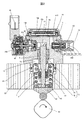
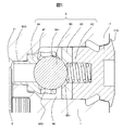
- the block diagram of the engine system to which the high pressure fuel pump of a present Example was applied is shown. It is a longitudinal cross-sectional view of the high pressure fuel pump of the Example of a present Example. It is the horizontal direction sectional view seen from the upper direction of the high pressure fuel pump of the Example of a present Example. It is the longitudinal cross-sectional view seen from the direction different from FIG. 1 of the high pressure fuel pump of the Example of a present Example. It is a longitudinal cross-sectional view of the valve closing state of the discharge valve mechanism of a present Example. It is a cross-sectional view of the valve open state of the discharge valve mechanism of a present Example. It is a cross-sectional view containing the discharge valve mechanism of a present Example, and a pressurization chamber return relief valve. It is a cross-sectional view containing the discharge valve mechanism of a present Example, and a low pressure chamber return relief valve.
- FIG. 1 shows the overall configuration of the engine system.
- the portion surrounded by a broken line shows the main body of a high pressure fuel pump (hereinafter referred to as a high pressure fuel pump), and the mechanism / parts shown in the broken line show that it is integrally incorporated into the pump body 1 .
- FIG. 1 is a diagram schematically showing the operation of the engine system, and the detailed configuration is different from the configuration of the high pressure fuel pump of FIG.
- FIG. 2 shows a longitudinal sectional view of the high pressure fuel pump of the present embodiment
- FIG. 3 is a horizontal sectional view of the high pressure fuel pump as viewed from above.
- FIG. 4 is a longitudinal sectional view of the high pressure fuel pump as viewed in a direction different from that of FIG.
- the fuel of the fuel tank 20 is pumped up by a feed pump 21 based on a signal from an engine control unit 27 (hereinafter referred to as an ECU).
- the fuel is pressurized to an appropriate feed pressure and sent through the suction pipe 28 to the low pressure fuel inlet 10a of the high pressure fuel pump.
- the fuel that has passed through the suction joint 51 from the low pressure fuel suction port 10a reaches the suction port 31b of the solenoid valve mechanism 300 that constitutes the capacity variable mechanism through the damper chamber (10b, 10c) in which the pressure pulsation reduction mechanism 9 is disposed.
- the solenoid valve mechanism 300 constitutes a solenoid suction valve mechanism.
- the fuel flowing into the solenoid valve mechanism 300 passes through the suction port opened and closed by the suction valve 30 and flows into the pressure chamber 11.
- a power to reciprocate the plunger 2 is given by the cam mechanism 93 of the engine.
- the reciprocating motion of the plunger 2 sucks the fuel from the suction valve 30 during the downward stroke of the plunger 2 and the fuel is pressurized during the upward stroke.
- the pressurized fuel is pressure-fed through the discharge valve mechanism 8 to the common rail 23 on which the pressure sensor 26 is mounted.
- the injector 24 injects fuel to the engine based on the signal from the ECU 27.
- This embodiment is a high pressure fuel pump applied to a so-called direct injection engine system in which the injector 24 directly injects fuel into the cylinder of the engine.
- the high-pressure fuel pump discharges the desired fuel flow rate of the supplied fuel in response to a signal from the ECU 27 to the solenoid valve mechanism 300.
- the high pressure fuel pump of the present embodiment is closely fixed to the high pressure fuel pump mounting portion 90 of the internal combustion engine.
- screw holes 1b are formed in a mounting flange 1a provided on the pump body 1, and a plurality of bolts (not shown) are inserted into the screw holes 1b.
- the mounting flange 1a is in close contact with and fixed to the high pressure fuel pump mounting portion 90 of the internal combustion engine.
- An O-ring 61 is fitted into the pump body 1 for sealing between the high pressure fuel pump mounting portion 90 and the pump body 1 to prevent engine oil from leaking outside.
- a cylinder 6 is attached to the pump body 1 to guide the reciprocating movement of the plunger 2 and to form a pressure chamber 11 together with the pump body 1. That is, the plunger 2 reciprocates inside the cylinder to change the volume of the pressure chamber.
- a solenoid valve mechanism 300 for supplying fuel to the pressure chamber 11 and a discharge valve mechanism 8 for discharging fuel from the pressure chamber 11 to the discharge passage are provided.
- the cylinder 6 is press-fit with the pump body 1 at its outer peripheral side.
- the pump body 1 is formed with an insertion hole for inserting the cylinder 6 from the lower side, and an inner peripheral convex portion deformed to the inner peripheral side to be in contact with the lower surface of the fixing portion 6a of the cylinder 6 at the lower end of the insertion hole Be done.
- the upper surface of the inner peripheral convex portion of the pump body 1 presses the fixing portion 6a of the cylinder 6 upward in the figure, and the upper end surface of the cylinder 6 is sealed so that the fuel pressurized in the pressurizing chamber 11 does not leak to the low pressure side. ing.
- a tappet 92 which converts the rotational movement of the cam 93 attached to the camshaft of the internal combustion engine into vertical movement and transmits it to the plunger 2.
- the plunger 2 is crimped to the tappet 92 by a spring 4 through a retainer 15. As a result, the plunger 2 can be reciprocated up and down with the rotational movement of the cam 93.
- a plunger seal 13 held at the lower end portion of the inner periphery of the seal holder 7 is installed in a state where the plunger seal 13 slidably contacts the outer periphery of the plunger 2 at the lower portion in the drawing of the cylinder 6.
- the fuel in the sub chamber 7a is sealed to prevent the fuel from flowing into the internal combustion engine.
- lubricating oil including engine oil
- for lubricating sliding parts in the internal combustion engine is prevented from flowing into the inside of the pump body 1.
- a suction joint 51 is attached to the side surface of the pump body 1 of the high pressure fuel pump.
- the suction joint 51 is connected to a low pressure pipe that supplies fuel from the fuel tank 20 of the vehicle, and the fuel is supplied from here to the inside of the high pressure fuel pump.
- the suction filter 52 has a function of preventing foreign matter present between the fuel tank 20 and the low pressure fuel suction port 10a from being absorbed by the flow of fuel into the high pressure fuel pump.
- the fuel that has passed through the low pressure fuel suction port 10a travels to the pressure pulsation reducing mechanism 9 through the low pressure fuel suction passage vertically connected to the pump body 1 shown in FIG.
- the pressure pulsation reducing mechanism 9 is disposed in the damper chamber (10b, 10c) between the damper cover 14 and the upper end surface of the pump body 1, and is supported from the lower side by a holding member 9a disposed on the upper end surface of the pump body 1.
- Ru Specifically, the pressure pulsation reducing mechanism 9 is a metal damper configured by overlapping two metal diaphragms. A gas of 0.3 MPa to 0.6 MPa is enclosed inside the pressure pulsation reducing mechanism 9, and the outer peripheral edge portion is fixed by welding.
- Damper chambers (10b, 10c) communicating with the low pressure fuel suction port 10a and the low pressure fuel suction passage are formed on upper and lower surfaces of the pressure pulsation reducing mechanism 9, respectively.
- the holding member 9a is formed with a passage communicating the upper side and the lower side of the pressure pulsation reducing mechanism 9.
- the suction port 31 b is formed in communication with the suction valve seat member 31 forming the suction valve seat 31 a in the vertical direction.
- the terminal 46 is molded integrally with the connector so that the other end can be connected to the engine control unit side.
- the solenoid valve mechanism 300 will be described with reference to FIG.
- the plunger 2 moves in the direction of the cam 93 and is in the suction stroke state by the rotation of the cam 93, the volume of the pressurizing chamber 11 increases and the fuel pressure in the pressurizing chamber 11 decreases.
- the suction valve 30 is opened.
- the suction valve 30 contacts the stopper 32.
- the opening formed in the suction valve seat member 31 opens and opens. The fuel passes through the opening of the suction valve sheet member 31 and flows into the pressurizing chamber 11 through a hole formed in the pump body 1 in the lateral direction.
- the rod biasing spring 40 biases the rod convex portion 35a which is convex on the outer diameter side of the rod 35, and is set to have a biasing force necessary and sufficient to open the suction valve 30 in the non-energized state.
- the volume of the pressure chamber 11 decreases with the upward movement of the plunger 2. In this state, the fuel once sucked into the pressure chamber 11 passes through the opening of the suction valve 30 in the open state again through the suction passage. Since the pressure is returned to 10d, the pressure in the pressure chamber does not rise. This process is called a return process.
- the suction valve 30 is closed by the biasing force of the suction valve biasing spring 33 and the fluid force caused by the fuel flowing into the suction passage 10d.
- the fuel pressure in the pressure chamber 11 rises with the upward movement of the plunger 2, and when the pressure in the fuel outlet 12 becomes higher than that, the high pressure fuel is discharged through the discharge valve mechanism 8 to the common rail 23. Supplied. This stroke is called a discharge stroke.
- the upward stroke from the lower start point to the upper start point of the plunger 2 consists of a return stroke and a discharge stroke. Then, by controlling the energization timing of the coil 43 of the solenoid valve mechanism 300, it is possible to control the amount of high pressure fuel to be discharged.
- the plunger 2 has a large diameter portion 2a and a small diameter portion 2b, and the volume of the sub chamber 7a is increased or decreased by the reciprocating movement of the plunger.
- the sub chamber 7a is in communication with the damper chamber (10b, 10c) by the fuel passage 10e.
- the flow rate of fuel into and out of the pump in the suction stroke or return stroke of the pump can be reduced, and the pressure pulsation generated inside the high pressure fuel pump can be reduced.
- the discharge valve mechanism 8 is provided at the outlet of the pressure chamber 11.
- the discharge valve mechanism 8 comprises a discharge valve seat 8a, a discharge valve 8b contacting and separating with the discharge valve seat 8a, and a discharge valve 8b.
- the discharge valve spring 8c is biased toward the seat 8a, and the discharge valve stopper 8d determines the stroke (moving distance) of the discharge valve 8b.
- the discharge valve stopper 8d and the pump body 1 are joined by welding at the contact portion 8e to block the fuel from the outside.
- the discharge valve 8b In the state where there is no fuel pressure difference between the pressurizing chamber 11 and the discharge valve chamber 12a, the discharge valve 8b is crimped to the discharge valve seat 8a by the biasing force of the discharge valve spring 8c and is in a closed state.
- the discharge valve 8b opens against the discharge valve spring 8c.
- the high pressure fuel in the pressure chamber 11 is discharged to the common rail 23 through the discharge valve chamber 12 a, the fuel discharge passage 12 b, and the fuel discharge port 12.
- the discharge valve 8 b When the discharge valve 8 b is opened, the discharge valve 8 b contacts the discharge valve stopper 8 d and the stroke is limited. Therefore, the stroke of the discharge valve 8b is appropriately determined by the discharge valve stopper 8d. As a result, the stroke is too large, and it is possible to prevent the fuel discharged to a high pressure into the discharge valve chamber 12a from flowing back into the pressure chamber 11 again due to the delay of closing the discharge valve 8b. Can be suppressed.
- the discharge valve 8 b When the fuel in the pressure chamber 11 is pressurized and the discharge valve 8 b is opened, the high pressure fuel in the pressure chamber 11 is discharged from the fuel discharge port 12 through the discharge valve chamber 80 and the fuel discharge passage.
- the fuel discharge port 12 is formed in a discharge joint 60, and the discharge joint 60 is welded and fixed to the pump body 1 at a welding portion to secure a fuel passage.
- the relief valve mechanism 200 includes a relief body 201, a relief valve 202, a relief valve holder 203, a relief spring 204, and a spring stopper 205.
- the relief body 201 is provided with a tapered seat portion. The load of the relief spring 204 is loaded through the valve holder 203, and the valve 202 is pressed against the seat portion of the relief body 201 and cooperates with the seat portion to shut off the fuel.
- the pressure of the fuel discharge port 12 becomes abnormally high pressure due to a failure of the electromagnetic suction valve 300 of the high pressure fuel pump, etc. and becomes larger than the set pressure of the relief valve mechanism 200, the abnormally high pressure fuel is on the low pressure side via the relief passage 213
- the damper chamber 10c is relieved.
- the relief destination of the relief valve mechanism 200 is the damper chamber 10 b, the relief chamber may be configured to relieve the pressure chamber 11.
- the discharge valve mechanism 8 in the present embodiment will be described using FIGS. 5 to 8.
- the discharge valve 8b of the discharge valve mechanism 8 is a poppet valve as shown in FIG. 3, there is a problem that the number of processing steps is increased and the manufacturing cost is increased since it is necessary to cut and discharge the discharge valve 8b.
- the discharge valve mechanism 8 is made into a unit type
- FIG. 5 shows a state in which the discharge valve 8B of the discharge valve mechanism 8 is in contact with the discharge valve seat 8F of the discharge valve seat member 8A and is closed.
- FIG. 6 shows a state where the discharge valve 8B of the discharge valve mechanism 8 is separated from the discharge valve seat 8F of the discharge valve seat member 8A and is opened.
- the discharge valve mechanism 8 of the present embodiment is a discharge valve 8B disposed on the discharge side of the pressure chamber 11, a discharge valve seat 8F on which the discharge valve 8B is seated, and a discharge valve seat 8F. And an opposing member 8D (stopper) positioned on the opposite side of the discharge valve seat 8F with the discharge valve 8B interposed therebetween.
- a stroke direction restricting portion 8D1 for restricting the displacement of the discharge valve 8B in the stroke direction is formed on the tapered surface of the opposing member 8D.
- the stroke direction restricting portion 8D1 on the tapered surface of the opposing member 8D, the movement of the discharge valve 8B in the stroke direction can be stabilized even if the discharge valve 8B is formed by an inexpensive ball valve. It is possible to regulate. Therefore, it becomes possible to constitute a discharge valve mechanism with high reliability at low cost.
- the discharge valve 8B is configured by a ball valve. According to this configuration, since the discharge valve 8B is formed by an inexpensive ball valve, the discharge valve mechanism can be formed at low cost. Further, according to this configuration, it is possible to provide a high pressure fuel pump which secures the oil tight performance even at high fuel pressure, and which has a small and light discharge valve mechanism.
- the discharge valve mechanism 8 includes a discharge valve chamber 80 in which the discharge valve mechanism 8 having the discharge valve 8B and the discharge valve seat 8F is disposed, and the opposing member 8D (stopper) is a plug member 17 (Sealing plug) is configured separately.
- the large diameter opposing member 8D (stopper) is fixed to the small diameter inner peripheral portion of the pump body 1 by press fitting.
- the opposing member 8D (stopper) may be configured by a plug member 17 (sealing plug) that shuts off the discharge valve chamber 80 from the outside. According to this configuration, since the opposing member 8D (stopper) can be integrally configured by the plug member 17 (sealing plug), the discharge valve mechanism can be configured inexpensively.
- the discharge valve mechanism 8 is attached to the valve sheet member 8A, the discharge valve 8B for opening and closing the discharge flow path 81 by coming into contact with and separating from the discharge valve sheet 8F of the valve sheet member 8A, and the plug member 17 (sealing plug) And a discharge valve spring 8C for urging the discharge valve 8B toward the discharge valve seat 8F.
- the stroke direction restricting portion 8D1 for restricting the displacement of the discharge valve 8B in the stroke direction is formed on the tapered surface of the opposing member 8D.
- the opposing member 8D and the plug member 17 (seal plug) are separately provided in FIGS. 5 and 6, they may be integrated.
- the stroke restricting portion 8D is formed on the facing member 8D (plug member 17), but may be formed on the discharge joint 150. That is, the high pressure fuel pump of the present embodiment includes the discharge valve chamber 80 in which the discharge valve mechanism 8 having the discharge valve 8B and the discharge valve seat 8F is disposed, and the opposing member 8D is the discharge joint 60 fixed to the pump body 1 It may be composed of
- the discharge valve 8B contacts the discharge valve seat 8F of the discharge valve seat member 8A to form an annular contact surface 8F which can be kept oil-tight.
- the discharge valve spring 8C is attached to the opposing member 8D (plug member 17) and biases the discharge valve 8B toward the discharge valve seat 8F, that is, biases the discharge valve 8B in the valve closing direction.
- a radial direction restricting portion 8A1 that restricts displacement in a direction orthogonal to the stroke axis of the discharge valve 8B is formed. According to this configuration, even if the discharge valve 8B is configured by an inexpensive ball valve, it is possible to regulate the displacement in the direction orthogonal to the stroke axis of the discharge valve 8B. Therefore, it becomes possible to constitute a highly reliable discharge valve mechanism.
- the discharge valve axial direction restricting portion 8A1 in the discharge valve axial direction be formed so as to have approximately half or more of the diameter of the discharge valve 8B. As a result, it is possible to stably regulate the displacement in the direction orthogonal to the stroke axis of the discharge valve 8B, and it is possible to configure a highly reliable discharge valve mechanism.
- the length of the radial direction restricting portion 8A1 in the discharge valve axial direction be longer than the length to the tapered surface of the sealing plug 17 (stroke of the discharge valve member 8B).
- the length of the radial direction restricting portion 8A1 in the discharge valve axial direction be longer than the length to the tapered surface of the sealing plug 17 (stroke of the discharge valve member 8B).
- a radial flow passage 8A2 for flowing the fuel discharged through the ball valve 8B toward the radially outer side of the discharge valve mechanism 8 is formed in the radial restriction portion 8A1 of the discharge valve seat member 8A where the discharge valve seat 8F is formed. It is done.
- radial direction flow-path 8 A2 it is desirable to form in multiple numbers by the outer periphery of a discharge valve seat. If the necessary flow passage area of the radial flow passage 8A2 can be secured, it is possible to make the shape of a circle, an ellipse, a long hole, a square or the like.
- a necessary flow path can be secured by forming a plurality of radial flow paths 8A2 on the outer periphery of the discharge valve seat.
- the discharge valve seat member 8A on which the discharge valve seat 8F is formed is press fitted into the pump body 1 and the opposing member (sealing plug 17) is welded to the pump body 1
- the valve seat member 8A on which the discharge valve seat is formed and the opposing member (sealing plug 17) are separately formed separately from each other.
- the fuel that has passed through the discharge valve seat member 8A flows from the discharge valve chamber 80 through the communication passage 110 to the fuel discharge port 12 and is discharged from the high pressure fuel pump.
- a relief valve mechanism 200 is disposed at the fuel discharge port 12.
- the radial direction restricting portion 8A1 may be formed on the sealing plug 17 side.
- the radial flow passage 8A2 may be formed on the side of the sealing plug 17 as well.
- the fuel discharged through the discharge valve 8B exceeds the set pressure, the fuel is supplied to the low pressure flow path such as the pressurizing chamber 11, the pressure pulsation reduction mechanism 9, and the suction passage 10b.
- the relief valve mechanism 200 is provided. Then, the fuel discharged from the pressure chamber 11 flows through the discharge valve chamber 80, then flows through the communication passage 110 in which the relief valve mechanism 200 is disposed, and is discharged from the fuel discharge port 12.
- the fuel discharged through the discharge valve 8B is formed radially outside the discharge valve mechanism 8 and substantially horizontally in the pump body 1 constituting the pressurizing chamber 11. After flowing through the flow path, it flows through the relief valve chamber in which the relief valve mechanism 200 is disposed, and is discharged from the fuel discharge port 12.
- the number of processing steps of the discharge valve 8B can be reduced, the valve body can be manufactured at low cost, and the high pressure fuel pump can be realized without increasing the size thereof.
- the discharge valve 8B has a curved contact portion, when a high back pressure is applied, the sheet portion is minutely deformed by the Hertzian contact to form a seal surface, and high oil tightness is achieved. It is possible to demonstrate the nature. Therefore, it is possible to provide a high pressure fuel pump having a compact and lightweight discharge valve structure, which ensures oil tightness even at high fuel pressure.
Landscapes
- Engineering & Computer Science (AREA)
- Mechanical Engineering (AREA)
- General Engineering & Computer Science (AREA)
- Chemical & Material Sciences (AREA)
- Combustion & Propulsion (AREA)
- Fuel-Injection Apparatus (AREA)
Priority Applications (4)
| Application Number | Priority Date | Filing Date | Title |
|---|---|---|---|
| EP18831886.9A EP3653867B1 (de) | 2017-07-14 | 2018-06-25 | Hochdruckbrennstoffpumpe |
| US16/627,921 US11248573B2 (en) | 2017-07-14 | 2018-06-25 | High-pressure fuel pump |
| CN201880044640.9A CN110832188B (zh) | 2017-07-14 | 2018-06-25 | 高压燃料泵 |
| JP2019529033A JP6934519B2 (ja) | 2017-07-14 | 2018-06-25 | 高圧燃料ポンプ |
Applications Claiming Priority (2)
| Application Number | Priority Date | Filing Date | Title |
|---|---|---|---|
| JP2017-137638 | 2017-07-14 | ||
| JP2017137638 | 2017-07-14 |
Publications (1)
| Publication Number | Publication Date |
|---|---|
| WO2019012970A1 true WO2019012970A1 (ja) | 2019-01-17 |
Family
ID=65001224
Family Applications (1)
| Application Number | Title | Priority Date | Filing Date |
|---|---|---|---|
| PCT/JP2018/023945 Ceased WO2019012970A1 (ja) | 2017-07-14 | 2018-06-25 | 高圧燃料ポンプ |
Country Status (5)
| Country | Link |
|---|---|
| US (1) | US11248573B2 (de) |
| EP (1) | EP3653867B1 (de) |
| JP (1) | JP6934519B2 (de) |
| CN (1) | CN110832188B (de) |
| WO (1) | WO2019012970A1 (de) |
Cited By (1)
| Publication number | Priority date | Publication date | Assignee | Title |
|---|---|---|---|---|
| WO2021140829A1 (ja) * | 2020-01-07 | 2021-07-15 | 日立Astemo株式会社 | 吐出弁機構及びそれを備えた高圧燃料供給ポンプ |
Families Citing this family (2)
| Publication number | Priority date | Publication date | Assignee | Title |
|---|---|---|---|---|
| WO2018003415A1 (ja) * | 2016-06-27 | 2018-01-04 | 日立オートモティブシステムズ株式会社 | 高圧燃料供給ポンプ |
| WO2018186219A1 (ja) * | 2017-04-07 | 2018-10-11 | 日立オートモティブシステムズ株式会社 | 高圧燃料ポンプ |
Citations (5)
| Publication number | Priority date | Publication date | Assignee | Title |
|---|---|---|---|---|
| JP2009531577A (ja) * | 2006-01-31 | 2009-09-03 | ローベルト ボツシユ ゲゼルシヤフト ミツト ベシユレンクテル ハフツング | 内燃機関に燃料を供給するための高圧ポンプ |
| JP2011080391A (ja) | 2009-10-06 | 2011-04-21 | Hitachi Automotive Systems Ltd | 高圧燃料供給ポンプの吐出弁機構 |
| WO2015163246A1 (ja) | 2014-04-25 | 2015-10-29 | 日立オートモティブシステムズ株式会社 | 高圧燃料供給ポンプ |
| WO2016098482A1 (ja) * | 2014-12-18 | 2016-06-23 | 日立オートモティブシステムズ株式会社 | バルブ機構及びこれを備えた高圧燃料供給ポンプ |
| US20170159629A1 (en) * | 2014-04-15 | 2017-06-08 | Robert Bosch Gmbh | High-pressure fuel pump including a discharge valve with a valve ball and a valve body |
Family Cites Families (11)
| Publication number | Priority date | Publication date | Assignee | Title |
|---|---|---|---|---|
| DE4306921A1 (de) * | 1993-03-05 | 1994-09-08 | Bosch Gmbh Robert | Förderpumpe für ein hydraulisches System |
| JP3633314B2 (ja) | 1998-10-14 | 2005-03-30 | 三菱電機株式会社 | 高圧燃料ポンプ装置 |
| IT1315828B1 (it) * | 1999-02-18 | 2003-03-26 | Daimler Chrysler Ag | Dispositivo di fissaggio per connettere un piattello per la molla diuna valvola con lo stelo della valvola. |
| DE10355030A1 (de) * | 2003-11-25 | 2005-06-23 | Robert Bosch Gmbh | Ventil, insbesondere für eine Hochdruckpumpe einer Kraftstoffeinspritzeinrichtung für eine Brennkraftmaschine |
| JP4390281B2 (ja) * | 2005-02-04 | 2009-12-24 | 日本特殊陶業株式会社 | 逆止弁 |
| JP2008106620A (ja) | 2006-10-23 | 2008-05-08 | Denso Corp | ポンプ |
| JP5039507B2 (ja) * | 2007-10-31 | 2012-10-03 | 日立オートモティブシステムズ株式会社 | 高圧燃料供給ポンプおよびその製造方法 |
| JP2010116979A (ja) * | 2008-11-13 | 2010-05-27 | Advics Co Ltd | 逆流防止装置 |
| DE102013215275A1 (de) * | 2013-08-02 | 2015-02-05 | Robert Bosch Gmbh | Kraftstoffhochdruckpumpe, mit einem Auslassventil |
| DE102014212646B4 (de) | 2014-04-15 | 2025-03-20 | Robert Bosch Gmbh | Kraftstoff-Hochdruckpumpe, mit einem Auslassventil mit einem Ventilkörper und einer Ventilkugel |
| DE102014222873A1 (de) * | 2014-11-10 | 2016-05-12 | Robert Bosch Gmbh | Kraftstoff-Hochdruckpumpe für ein Kraftstoffsystem für eine Brennkraftmaschine |
-
2018
- 2018-06-25 JP JP2019529033A patent/JP6934519B2/ja active Active
- 2018-06-25 US US16/627,921 patent/US11248573B2/en active Active
- 2018-06-25 CN CN201880044640.9A patent/CN110832188B/zh active Active
- 2018-06-25 EP EP18831886.9A patent/EP3653867B1/de active Active
- 2018-06-25 WO PCT/JP2018/023945 patent/WO2019012970A1/ja not_active Ceased
Patent Citations (5)
| Publication number | Priority date | Publication date | Assignee | Title |
|---|---|---|---|---|
| JP2009531577A (ja) * | 2006-01-31 | 2009-09-03 | ローベルト ボツシユ ゲゼルシヤフト ミツト ベシユレンクテル ハフツング | 内燃機関に燃料を供給するための高圧ポンプ |
| JP2011080391A (ja) | 2009-10-06 | 2011-04-21 | Hitachi Automotive Systems Ltd | 高圧燃料供給ポンプの吐出弁機構 |
| US20170159629A1 (en) * | 2014-04-15 | 2017-06-08 | Robert Bosch Gmbh | High-pressure fuel pump including a discharge valve with a valve ball and a valve body |
| WO2015163246A1 (ja) | 2014-04-25 | 2015-10-29 | 日立オートモティブシステムズ株式会社 | 高圧燃料供給ポンプ |
| WO2016098482A1 (ja) * | 2014-12-18 | 2016-06-23 | 日立オートモティブシステムズ株式会社 | バルブ機構及びこれを備えた高圧燃料供給ポンプ |
Non-Patent Citations (1)
| Title |
|---|
| See also references of EP3653867A4 |
Cited By (5)
| Publication number | Priority date | Publication date | Assignee | Title |
|---|---|---|---|---|
| WO2021140829A1 (ja) * | 2020-01-07 | 2021-07-15 | 日立Astemo株式会社 | 吐出弁機構及びそれを備えた高圧燃料供給ポンプ |
| JPWO2021140829A1 (de) * | 2020-01-07 | 2021-07-15 | ||
| US20230029119A1 (en) * | 2020-01-07 | 2023-01-26 | Hitachi Astemo, Ltd. | Discharge valve mechanism and high-pressure fuel supply pump including the same |
| JP7273196B2 (ja) | 2020-01-07 | 2023-05-12 | 日立Astemo株式会社 | 吐出弁機構及びそれを備えた高圧燃料供給ポンプ |
| US11781513B2 (en) | 2020-01-07 | 2023-10-10 | Hitachi Astemo, Ltd. | Discharge valve mechanism and high-pressure fuel supply pump including the same |
Also Published As
| Publication number | Publication date |
|---|---|
| CN110832188A (zh) | 2020-02-21 |
| JPWO2019012970A1 (ja) | 2020-03-19 |
| EP3653867B1 (de) | 2024-02-21 |
| JP6934519B2 (ja) | 2021-09-15 |
| US11248573B2 (en) | 2022-02-15 |
| CN110832188B (zh) | 2022-09-16 |
| EP3653867A4 (de) | 2021-04-07 |
| EP3653867A1 (de) | 2020-05-20 |
| US20200132029A1 (en) | 2020-04-30 |
Similar Documents
| Publication | Publication Date | Title |
|---|---|---|
| CN111322187B (zh) | 高压燃料供给泵 | |
| JP6633195B2 (ja) | 高圧燃料供給ポンプ | |
| EP3543519B1 (de) | Hochdruckbrennstoffförderpumpe | |
| JP6934519B2 (ja) | 高圧燃料ポンプ | |
| JP2018087548A (ja) | 高圧燃料供給ポンプ | |
| WO2019107101A1 (ja) | 高圧燃料供給ポンプ | |
| JP7139265B2 (ja) | 高圧燃料供給ポンプ及びリリーフ弁機構 | |
| JP6572241B2 (ja) | バルブ機構、及びこれを備えた高圧燃料供給ポンプ | |
| JP7316466B2 (ja) | 燃料ポンプ | |
| JP2021188544A (ja) | 燃料ポンプ | |
| JP7178504B2 (ja) | 燃料ポンプ | |
| JP2019090365A (ja) | 燃料供給ポンプ | |
| JP2023071061A (ja) | 燃料ポンプ | |
| JP7385750B2 (ja) | 燃料ポンプ | |
| JP7518980B2 (ja) | 燃料ポンプ | |
| JP2019090366A (ja) | リリーフ弁機構およびこれを備えた燃料供給ポンプ | |
| JP6596542B2 (ja) | バルブ機構及びこれを備えた高圧燃料供給ポンプ | |
| CN111989481B (zh) | 燃料供给泵以及燃料供给泵的制造方法 | |
| WO2019012998A1 (ja) | 高圧燃料ポンプ | |
| JP6385840B2 (ja) | バルブ機構及びこれを備えた高圧燃料供給ポンプ | |
| WO2022269977A1 (ja) | 電磁吸入弁機構及び燃料ポンプ | |
| WO2023209949A1 (ja) | 燃料ポンプ |
Legal Events
| Date | Code | Title | Description |
|---|---|---|---|
| 121 | Ep: the epo has been informed by wipo that ep was designated in this application |
Ref document number: 18831886 Country of ref document: EP Kind code of ref document: A1 |
|
| ENP | Entry into the national phase |
Ref document number: 2019529033 Country of ref document: JP Kind code of ref document: A |
|
| NENP | Non-entry into the national phase |
Ref country code: DE |
|
| ENP | Entry into the national phase |
Ref document number: 2018831886 Country of ref document: EP Effective date: 20200214 |