WO2019013031A1 - Moteur - Google Patents
Moteur Download PDFInfo
- Publication number
- WO2019013031A1 WO2019013031A1 PCT/JP2018/025057 JP2018025057W WO2019013031A1 WO 2019013031 A1 WO2019013031 A1 WO 2019013031A1 JP 2018025057 W JP2018025057 W JP 2018025057W WO 2019013031 A1 WO2019013031 A1 WO 2019013031A1
- Authority
- WO
- WIPO (PCT)
- Prior art keywords
- substrate
- frame
- protrusion
- contact
- outer peripheral
- Prior art date
- Legal status (The legal status is an assumption and is not a legal conclusion. Google has not performed a legal analysis and makes no representation as to the accuracy of the status listed.)
- Ceased
Links
Images







Classifications
-
- H—ELECTRICITY
- H02—GENERATION; CONVERSION OR DISTRIBUTION OF ELECTRIC POWER
- H02K—DYNAMO-ELECTRIC MACHINES
- H02K11/00—Structural association of dynamo-electric machines with electric components or with devices for shielding, monitoring or protection
- H02K11/20—Structural association of dynamo-electric machines with electric components or with devices for shielding, monitoring or protection for measuring, monitoring, testing, protecting or switching
- H02K11/21—Devices for sensing speed or position, or actuated thereby
- H02K11/215—Magnetic effect devices, e.g. Hall-effect or magneto-resistive elements
-
- H—ELECTRICITY
- H02—GENERATION; CONVERSION OR DISTRIBUTION OF ELECTRIC POWER
- H02K—DYNAMO-ELECTRIC MACHINES
- H02K29/00—Motors or generators having non-mechanical commutating devices, e.g. discharge tubes or semiconductor devices
- H02K29/06—Motors or generators having non-mechanical commutating devices, e.g. discharge tubes or semiconductor devices with position sensing devices
- H02K29/08—Motors or generators having non-mechanical commutating devices, e.g. discharge tubes or semiconductor devices with position sensing devices using magnetic effect devices, e.g. Hall-plates, magneto-resistors
-
- H—ELECTRICITY
- H02—GENERATION; CONVERSION OR DISTRIBUTION OF ELECTRIC POWER
- H02K—DYNAMO-ELECTRIC MACHINES
- H02K21/00—Synchronous motors having permanent magnets; Synchronous generators having permanent magnets
- H02K21/12—Synchronous motors having permanent magnets; Synchronous generators having permanent magnets with stationary armatures and rotating magnets
- H02K21/14—Synchronous motors having permanent magnets; Synchronous generators having permanent magnets with stationary armatures and rotating magnets with magnets rotating within the armatures
- H02K21/16—Synchronous motors having permanent magnets; Synchronous generators having permanent magnets with stationary armatures and rotating magnets with magnets rotating within the armatures having annular armature cores with salient poles
-
- H—ELECTRICITY
- H02—GENERATION; CONVERSION OR DISTRIBUTION OF ELECTRIC POWER
- H02K—DYNAMO-ELECTRIC MACHINES
- H02K2211/00—Specific aspects not provided for in the other groups of this subclass relating to measuring or protective devices or electric components
- H02K2211/03—Machines characterised by circuit boards, e.g. pcb
Definitions
- the present invention relates to a motor, and more particularly to a motor having a substrate provided with a sensor.
- some motors such as brushless motors have a substrate provided with a sensor.
- Patent Document 1 discloses a motor driving circuit board holding device having a structure in which a driving circuit board is engaged with a board holding portion of an end surface insulating portion provided on a stator core.
- An object of the present invention is to provide a motor capable of arranging a sensor at a desired position.
- a motor includes a frame, a rotor, a stator, a substrate provided on the stator, and a sensor provided on the substrate, the substrate facing the rotor And an outer peripheral portion, the outer peripheral portion of the substrate is provided with a contact portion which contacts the inner peripheral portion of the frame, and the inner peripheral portion of the frame is a contact portion which contacts the outer peripheral portion of the substrate Is provided, and at least one of the contact portion and the contact portion is provided with a protrusion projecting toward the other.
- the protrusion protrudes on the other side with respect to the annular contour of the outer periphery of the substrate on which one is provided or the inner periphery of the frame.
- the contact portion in contact with the contact portion is biased radially and / or circumferentially.
- the substrate is at a radially biased position towards a portion of the frame.
- one has a plurality of protrusions, and the plurality of protrusions are unevenly distributed in the circumferential direction.
- the stator has a stator core and a resin member, and the resin member is between the stator core and the substrate in the rotational axis direction, and the outer peripheral portion of the substrate is provided with a recess recessed in the radial direction Has a protrusion extending in the rotational axis direction, and the protrusion is inside the recess.
- the resin member is attached to the stator core, and the convex portion is a positioning portion of the substrate.
- the contact portion and the recess are unevenly distributed in different regions in the circumferential direction.
- the contact portion is provided on the contact portion, and the contact portion is an inner peripheral surface curved along the outer peripheral portion of the substrate in the circumferential direction.
- the protrusion is provided in the contact portion, and the protrusion protrudes in the radial direction toward the outer periphery of the substrate.
- the contact portion is a side surface of the outer peripheral portion of the substrate which is curved along the inner peripheral portion of the frame in the circumferential direction.
- the contact portion and the contact portion are at mutually different positions in the circumferential direction, and the contact portion has a first protrusion projecting toward the inner circumferential portion of the frame in the radial direction, and the contact portion Has a second protrusion projecting toward the outer periphery of the substrate in the radial direction.
- the direction parallel to the rotation axis of the motor may be referred to as the rotation axis direction.
- a direction perpendicular to the rotation axis may be referred to as a radial direction.
- the direction which rotates centering on a rotating shaft may be called circumferential direction.
- the direction of the rotation axis may be referred to as the vertical direction (the direction in which the rotation axis protrudes from the housing of the motor is upward).
- a plane perpendicular to the rotation axis may be referred to as a horizontal plane.
- “upper and lower”, “upper”, “lower”, “horizontal”, etc. are the methods adopted for convenience when focusing on only the motor, and the direction in the device on which the motor is mounted and the motor There is no limitation on the posture in which is used.
- FIG. 1 is a perspective view showing a motor 1 according to a first embodiment of the present invention.
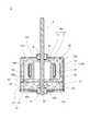
- FIG. 2 is a side sectional view showing the motor 1.
- FIG. 3 is an exploded top perspective view of the motor 1.
- FIG. 4 is an exploded lower perspective view of the motor 1.
- the arrow D indicates the rotation axis direction.
- the motor 1 is a brushless motor. As shown in FIG. 1, the motor 1 has a frame 11, a rotating shaft 2 and a cover 12. The motor 1 has a shape in which a rotation shaft 2 protrudes upward (upward) from a cylindrical housing 10 configured by a frame 11 and a cover 12.
- An opening is provided in a part of the cover 12, and the connector 55 disposed on the lower surface of the substrate 40 (FIG. 2) is exposed through the opening.
- electric power can be supplied to the motor 1 from the outside of the housing 10 of the motor 1 via the connector 55.
- a bearing 9 is disposed at the center of the cover 12 (described later).
- the frame 11 has a cylindrical portion 11 m and a top surface 11 l closing one end of the cylindrical portion 11 m, that is, the upper end.
- the frame 11 roughly has a cup shape or a cylindrical shape with a bottom.
- a cover 12 is attached to the other or lower opening of the frame 11.
- the cylindrical portion of the frame 11 has a circular, cylindrical shape when viewed from above.
- the rotation axis 2 penetrates the top surface 11 l of the frame 11.
- a bearing 8 is held on the top surface 11 l of the frame 11.
- the rotating shaft 2 is supported by a bearing 8.
- the rotation axis 2 is rotatable with respect to the frame 11.
- the rotation axis 2 is disposed substantially perpendicular to the top surface 11 l of the frame 11.
- the rotation axis 2 is located at the center of the cylindrical portion 11 m of the frame 11 in plan view (as viewed from above).
- the rotation shaft 2 protrudes upward from the top surface 11 l of the frame 11 when viewed from the frame 11.
- a hole 11h is formed in the top surface of the frame 11.
- the hole 11 h is used, for example, when the motor 1 is attached to an external device and used.
- a screw or the like can be attached to the hole 11 h.
- a bearing 9 is disposed at the center of the cover 12.
- the bearing 9 is held by the cover 12.
- the rotating shaft 2 is supported by a bearing 9.
- the rotary shaft 2 is rotatably supported relative to the frame 11 by two bearings, an upper bearing 8 and a lower bearing 9.
- the motor 1 has an internal space surrounded by the frame 11 and the cover 12. Various parts are accommodated in the interior space. That is, inside the frame 11, the rotor 2a, the elastic member 15, the stator 20, the substrate 40 and the like are arranged.
- the motor 1 is a so-called inner rotor type motor.
- the annular stator 20 is disposed along the inner circumferential portion 11 a of the cylindrical portion 11 m of the frame 11.
- the stator 20 surrounds the rotating shaft 2.
- the outer peripheral surface of the rotor 2 a (that is, the outer peripheral surface of the magnet 3) is surrounded by the stator 20.
- the rotor 2 a has a magnet 3 and a yoke 4.
- the yoke 4 has a cup shape having a cylindrical portion 4m and a top surface 4l covering the upper end of the cylindrical portion 4m. That is, the yoke 4 has a cylindrical shape having a top surface 4 l. The lower end of the yoke 4 is an opening.
- the yoke 4 may not be cup-shaped, but may be a cylindrical core or the like.
- the planar shape of the magnet 3 is annular.
- the magnet 3 is attached to the magnet 3 with the inner peripheral surface of the magnet 3 facing the outer peripheral side surface of the cylindrical portion of the yoke 4.
- the outer peripheral surface of the magnet 3 is opposed to the inner peripheral surface of the stator core 23 of the stator 20.
- the rotation shaft 2 is disposed substantially perpendicular to the top surface 4 l of the yoke 4.
- the rotation shaft 2 penetrates the top surface 4 l of the yoke 4 and is fitted to the top surface 4 l of the yoke 4. Thereby, the rotating shaft 2 and the rotor 2a are mutually fixed.
- FIG. 5 is a lower exploded perspective view showing the structure of the stator 20 and the substrate 40. As shown in FIG.
- FIG. 5 illustration of patterns of conductor portions on the substrate 40, lands, various circuit elements and the like, and illustration of conductors 27 described later are omitted.
- the stator 20 has a stator core 23, a coil 25 and a resin member 30.
- the motor 1 is a three-phase brushless motor, and the number of slots is nine.
- the stator core 23 (FIG. 2) is configured, for example, by stacking steel plates (not shown).
- the stator core 23 has teeth 23 a extending toward the rotating shaft 2 from the side of the frame 11 (FIG. 2).
- the teeth 23 a face the outer peripheral surface of the magnet 3.
- stator core 23 is divided for each slot of stator 20.
- the present invention is not limited to this, and a plurality of slots may be integrated.
- the resin member 30 is attached to the stator core 23.
- the resin member 30 is an insulating member (insulator) that insulates the coil 25 and the stator core 23. In addition, the resin member 30 insulates the coil 25 and the frame 11.
- the coil 25 is wound around the stator core 23 via the resin member 30. That is, the coil 25 is wound around the resin member 30.
- the resin member 30 is attached to the stator core 23 for each slot, and the coil 25 is wound around the resin member 30.
- the resin member 30 of each slot extends above and below the stator core 23 near the outer periphery of the stator 20.
- a resin member 30 is provided between the coil 25 and the frame 11, and the coil 25 and the frame 11 are insulated.
- the positions of the lower end surfaces 31 of the resin members 30 of the respective slots are substantially the same in the rotational axis direction except for the portions where the convex portions 34 (34a, 34b, 34c) are provided as described later.
- the substrate 40 is disposed on the lower end surface 31 of the resin member 30. That is, the resin member 30 is located between the stator core 23 and the substrate 40 in the rotational axis direction.
- the substrate 40 is provided on the stator 20.
- the substrate 40 is disposed below the stator 20.
- the substrate 40 is disposed on the lower end surface 31 of the resin member 30.
- the substrate 40 has an annular contour whose dimension in the radial direction is smaller than that of the inner circumferential portion 11 a of the cylindrical portion of the frame 11.
- the substrate 40 has a substantially circular plate shape.
- the substrate 40 has an upper surface 40 a and a lower surface 40 b, and an outer peripheral portion 41.
- the upper surface 40 a and the lower surface 40 b are surrounded by the outer peripheral portion 41.
- a hole 42 through which the rotation shaft 2 passes is provided at a substantially central portion of the substrate 40.
- the substrate 40 is disposed in a posture substantially perpendicular to the rotation axis 2. That is, the upper surface 40 a of the substrate 40 is substantially perpendicular to the rotation axis 2.
- the upper surface 40a of the substrate 40 is a surface facing the rotor 2a.
- the substrate 40 is provided with a control circuit for driving the motor 1.
- the substrate 40 applies a drive current to each coil 25 of the motor 1 at a timing according to the rotation of the rotor 2 a to drive the motor 1.
- a sensor 53 is provided on the substrate 40.
- the sensor 53 is a Hall element.
- a sensor 53 is provided for each of the three phases. That is, three sensors 53 are provided.
- the sensor 53 is disposed on the upper surface 40 a of the substrate 40.
- the sensor 53 detects a magnetic field.
- the sensor 53 mainly detects the position of the magnetic pole of the magnet 3. That is, the sensor 53 detects the rotational position of the rotor 2a. As described later, since the sensor 53 is positioned to be at a predetermined position, detection accuracy by the sensor 53 is improved.
- a connector 55 is provided on the lower surface 40 b of the substrate 40.
- the illustration of the specific shape of the connector 55 is omitted.
- the connector 55 connects a power supply line or a signal line from an external device to the control circuit on the substrate 40.
- the elastic member 15 is disposed between the lower surface 40 b of the substrate 40 and the cover 12.
- the elastic member 15 is made of, for example, a resin having elasticity, such as natural rubber or synthetic rubber.
- the elastic member 15 is in contact with the vicinity of the outer peripheral portion 41 of the substrate 40 in a state of being curved in an annular shape.
- the elastic member 15 is compressed between the substrate 40 and the cover 12 in the rotational axis direction more than in a natural state (a state in which no external load is applied).
- a natural state a state in which no external load is applied.
- the substrate 40 is pressed against the stator 20 by the elastic member 15.
- the substrate 40 is fixed in the rotation axis direction in a state of being attached to the stator 20.
- the elastic member 15 is provided with a plurality of recesses 15 b that are recessed in the rotation axis direction. Thereby, compared with the case where the recessed part 15b is not provided, the spring constant of the rotation axis direction of the elastic member 15 is small.
- the substrate 40 is pressed upward by the elastic member 15 with an appropriate amount of force.
- the position of the recess 15 b corresponds to the position on the lower surface 40 b of the substrate 40 where the land, the lead wire, the circuit element and the like are provided.
- the elastic member 15 is not in contact with lands, wires, circuit elements and the like on the lower surface 40 b of the substrate 40.
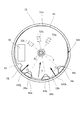
- FIG. 6 is a bottom view showing the mounting structure of the substrate 40 of the motor 1.
- FIG. 6 illustration of patterns of conductors on the substrate 40, lands, various circuit elements and the like is omitted except for a part.
- the motor 1 in a state in which the cover 12 and the elastic member 15 are not attached is shown, and a portion of the stator 20 and the rotor 2a which is hidden behind the substrate 40 is shown by a broken line.
- the sensors 53 (53a, 53b, 53c) on the upper surface 40a of the substrate 40 are shown by broken lines.
- lands 47 As shown in FIG. 6, on the lower surface 40b of the substrate 40, three lands 47 (47a, 47b, 47c) are provided. Three lands 47 are provided corresponding to the three phases of the motor 1. In the present embodiment, the land 47a corresponds to the U phase, the land 47b to the V phase, and the land 47c to the W phase.
- Each land 47 is connected to an end of a conducting wire 27 (27a, 27b, 27c) connected to the coil 25 of the corresponding phase.
- the conducting wire 27a corresponds to the U phase
- the conducting wire 27b to the V phase
- the conducting wire 27c to the W phase.
- the other end (not shown) of the conducting wire 27 of the coil 25 of each phase is connected to a common potential not shown.
- it is connected to a land (not shown) of a common potential provided on the lower surface 40 b of the substrate 40.
- the sensor 53a corresponds to the U phase, the sensor 53b to the V phase, and the sensor 53c to the W phase.
- the three sensors 53 are circumferentially spaced by 40 degrees. That is, the three sensors 53 are arranged in the circumferential direction at the same interval as the interval of the slots in the stator 20 in the circumferential direction.
- Each sensor 53 is disposed at a position overlapping the magnet 3 in the axial direction. That is, each sensor 53 is disposed at a position separated from the rotation axis 2 by substantially the same distance as the radius of the magnet 3.
- the circumferential position of each sensor 53 is positioned by positioning the substrate 40 as described later.
- one common line wiring portion 43 and three concave portions 44 are provided in the outer peripheral portion 41 of the substrate 40.
- the common line wiring portion 43 is a portion provided in a part of the outer peripheral portion 41 and recessed in the radial direction.
- a gap between the common line wiring portion 43 and the inner circumferential portion 11 a of the frame 11 is, for example, a wiring path of the common line.
- each of the three recesses 44 is a radially recessed portion provided in a part of the outer peripheral portion 41. As the rotation shaft 2 is approached, the circumferential dimension of the recess of each recess 44 decreases.
- each recess 44 has a tapered shape in which the dimension in the circumferential direction of the recess of each recess 44 decreases as the rotation shaft 2 is approached. That is, the end of each recess 44 has a contour extending linearly from the outer peripheral portion 41 to the vicinity of the tip portion 44p close to the rotation axis 2, and when viewed from the rotation axis direction, the rotation shaft 2 and the tip portion 44p It has a shape that is symmetrical with respect to a straight line passing through. In other words, each of the recessed portions 44 has a shape in which a fan-shaped portion centered on the vicinity of the tip end portion 44 p is cut away from the outer peripheral portion 41 as viewed roughly.
- a rounded portion (corner radiused portion) is provided at the corner between the contour of the recess 44 and the other part of the outer peripheral portion 41.
- a rounded portion (round corner portion) is also provided between the two fan-shaped radii of the recess 44, that is, the two lines forming the tapered shape of the contour of the recess 44.
- the tip end 44p of the recess 44 is close to the rotation shaft 2.
- the three recesses 44 are provided corresponding to the three phases of the motor 1.
- the recess 44 a corresponds to the U phase
- the recess 44 b to the V phase
- the recess 44 c to the W phase.
- the three recesses 44 are arranged in the circumferential direction at the same interval as the interval of the slots in the stator 20 in the circumferential direction.
- Each recess 44 is disposed at a position corresponding to three slots adjacent in the circumferential direction of the stator 20.
- the three recesses 44 are circumferentially spaced by 40 degrees.
- the recess 44 corresponding to a specific phase is provided in the outer peripheral portion 41 at a position opposite to the sensor 53 corresponding to that phase with respect to the rotational shaft 2.
- the sensor 53 and the recess 44 corresponding to the specific phase are disposed at positions where a distance of 180 degrees is secured in the circumferential direction. That is, the sensor 53a and the recess 44a corresponding to the U phase are arranged at positions separated by 180 degrees in the circumferential direction.
- the sensor 53b and the recess 44b corresponding to the V phase are disposed at positions separated by 180 degrees in the circumferential direction.
- the sensor 53c and the recess 44c corresponding to the W phase are disposed at positions separated by 180 degrees in the circumferential direction.
- the land 47 corresponding to a particular phase is provided in the vicinity of the recess 44 corresponding to that phase.
- Each land 47 is provided in the vicinity of the leading end 44 p of each recess 44.
- a contact portion 49 in contact with the inner peripheral portion 11 a of the frame 11 is provided on the outer peripheral portion 41 of the substrate 40.
- the contact portion 49 is two projecting portions 49 j and 49 k.
- the substrate 40 is attached to the motor 1 with the contact portion 49 in contact with the inner peripheral portion 11 a of the frame 11.
- a part of the inner circumferential portion 11a of the frame 11 is the contact portions 11j and 11k with which the contact portion 49 contacts.
- the inner circumferential portion 11a of the frame 11 has contacted portions 11j and 11k with which the two projecting portions 49j and 49k respectively contact.
- the to-be-contacted parts 11 j and 11 k are inner peripheral surfaces curved along the outer peripheral part 41 of the substrate 40 in the circumferential direction.
- the protrusions 49 j and 49 k are formed to protrude toward the inner peripheral portion 11 a of the frame 11 with respect to the annular contour of the outer peripheral portion 41 of the substrate 40.
- the protrusion 49 j and the protrusion 49 k are spaced apart from each other in the circumferential direction.
- the protrusions 49 j and 49 k are unevenly distributed in the circumferential direction.
- the protrusions 49 j and 49 k and the recess 44 are unevenly distributed in regions different from each other in the circumferential direction. That is, the protrusions 49 j and 49 k are at positions relatively away from the three recesses 44 in the circumferential direction.
- the protrusion 49 j and the protrusion 49 k are disposed at an interval of, for example, about 80 degrees in the circumferential direction.
- the recess 44 c closest to the protrusion 49 j and the protrusion 49 j are disposed at an interval of, for example, 80 degrees in the circumferential direction.
- the concave portion 44a closest to the projecting portion 49k and the projecting portion 49k are arranged at an interval of, for example, 120 degrees in the circumferential direction.
- the resin member 30 is provided with three convex portions 34 (34 a, 34 b, 34 c) extending in the rotation axis direction.
- the three projections 34 are provided on the resin member 30 of the three slots and extend downward.
- a step surface 33 is provided at substantially the same position as the lower end surface 31 of the other resin member 30 in the rotational axis direction.
- the convex portion 34 is a projecting portion that protrudes downward from the step surface 33.
- the three convex portions 34 are provided at positions corresponding to the three concave portions 44 of the substrate 40. That is, the convex portions 34 are provided on the resin members 30 of three slots adjacent in the circumferential direction.
- the outer circumferential surface of each convex portion 34 has a curved surface along the inner circumferential portion 11a of the frame 11, a plane facing inward in the radial direction, and two planes connecting the both and facing in both the circumferential direction and the radial direction. doing. Among these, assuming that the curved surface along the inner peripheral portion 11 a of the frame 11 is a plane, it can be said that the convex portion 34 has a trapezoidal outer surface as viewed from the rotation axis direction.
- the convex portion 34 has a substantially trapezoidal shape having a long side slightly curved along the inner peripheral portion 11 a of the frame 11 in a plan view.
- the radial dimension of the projection 34 is slightly smaller than the radial dimension of the recess 44.
- each convex portion 34 has a tapered shape in which the dimension in the circumferential direction decreases as the rotation axis 2 is approached. That is, the two outer side surfaces 35 of each convex portion 34 have a contour extending linearly from a curved surface along the inner peripheral portion 11 a of the frame 11 to a plane facing inward in the radial direction when viewed from the rotation axis direction.
- the convex portion 34 has a shape that is symmetrical with respect to a straight line passing through the rotation axis 2 when viewed from the rotation axis direction.
- the convex portion 34 is inside the concave portion 44.
- the convex portion 34 has two outer side surfaces 35 along the edge of the concave portion 44.
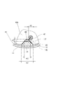
- FIG. 7 is an end view showing a schematic structure of a portion where the recess 44 is provided.
- FIG. 8 is a partially enlarged view showing a portion provided with the recess 44 as viewed from below.
- the lower end portion of the convex portion 34 is below the lower surface 40 b of the substrate 40.
- the inner end of the recess 44 is inside the position of the outer peripheral portion 41 of the substrate 40 in a portion where the recess 44 is not provided. Since the convex portion 34 is inside the concave portion 44, the circumferential displacement of the substrate 40 is restricted by the convex portion 34. That is, when the convex portion 34 is positioned inside the concave portion 44, the circumferential position of the substrate 40 with respect to the stator 20 is regulated.
- the convex portion 34 serves as a positioning portion of the substrate 40.
- the substrate 40 is held by the projections 34 so as not to rotate.
- the opening width w2 in the radial direction near the outer peripheral portion 41 of the recess 44 (here, the width in the direction perpendicular to the radial direction when viewed from the rotation axis direction) is And the width w1 of the convex portion 34 in a portion close to the rotation axis 2.
- a portion close to the rotation axis 2 of the convex portion 34 is in contact with or close to the edge of the concave portion 44 inside the concave portion 44.
- a gap 45 an example of a non-occupied region surrounded by the outer surface of the protrusion 34 and the edge of the recess 44 is formed.
- An area inside the concave portion 44 and close to the frame 11 is an occupied area 46 occupied by the convex portion 34. Since the outer side surface 35 of the projection 34 is along the edge of the recess 44, the occupied region 46 fills most of the region of the recess 44 near the frame 11 when viewed from the rotational axis direction. In the present embodiment, as viewed in the rotation axis direction, the area of the occupied region 46 is larger than the area of the gap 45 not occupied by the convex portion 34 in the region inside the concave portion 44.
- the width of the gap 45 is smaller than the width of the land 47.
- the radial width w3 of the gap 45 is smaller than the width d1 of the land 47. That is, the size of the gap 45 connecting the lower space of the substrate 40 and the upper space of the substrate 40 is relatively small.
- the conducting wire 27 extends from the lower surface 40 b of the substrate 40 through the gap 45 toward the stator 20.
- the end of the conductor 27 is electrically connected to the land 47 by a conductive member 48.
- the conductive member 48 is, for example, a solder.
- the outer surface 35 of the projection 34 is along the edge of the recess 44, the occupied area 46 is relatively large, and the gap 45 is relatively narrow. Therefore, the foreign matter is prevented from entering the space above the substrate 40.
- the conductive member 48 becomes a lump having a width as large as the width of the land 47. Since the width of the gap 45 is smaller than the width of the land 47 in the radial direction, the conductive member 48 may fall off the land 47 even when, for example, the conductor 27 is connected to the land 47. The conductive member 48 which has fallen is prevented from entering the space above the substrate 40.
- the solder As the conductive member 48, when the lead 27 is soldered to the land 47, even if a so-called solder ball is generated without the solder joining the land 47, the solder ball is higher than the substrate 40. It is prevented from entering the space. Therefore, the motor 1 can be manufactured more easily.
- the contact portion 49 is provided on the outer peripheral portion 41 of the substrate 40, and the contact portion 49 contacts the inner peripheral portion 11 a of the frame 11 to make the substrate 40 in the radial direction. It is energized.
- FIG. 9 is a bottom view showing the relationship between the substrate 40, the frame 11, and the convex portion 34. As shown in FIG.
- FIG. 9 the rotation axis 2, the substrate 40, the frame 11, and the resin member 30 are shown.
- the two-dot chain line virtually indicates the position of the substrate 40 when the contact portion 49 and the frame 11 do not contact with each other.
- the contact portion 49 of the substrate 40 contacts the contact portions 11 j and 11 k of the inner peripheral portion 11 a of the frame 11, whereby the biasing force of the frame 11 is exerted.
- (Indicated by arrows F1 and F2) act on the substrate 40.
- An arrow F1 indicates a biasing force generated by the projection 49j coming into contact with the contact portion 11j.
- An arrow F2 indicates a biasing force generated by the protrusion 49k coming into contact with the contact portion 11k. Each biasing force acts in the radial direction.
- the biasing force acting on the substrate 40 due to the provision of the two projecting portions 49 j and 49 k is a combination of the two biasing forces described above (indicated by the arrow F). Since the protrusions 49j and 49k are at positions relatively separated from the three recesses 44 in the circumferential direction, the substrate 40 is provided with the recesses 44 from the side on which the protrusions 49j and 49k are provided. The biasing force acts on the That is, the substrate 40 is biased by the frame 11, and the concave portion 44 is pushed toward the convex portion 34 of the resin member 30.
- the protrusions 49 j and 49 k protrude from the annular contour of the outer peripheral portion 41, and the protrusions 49 j and 49 k are of the frame 11. Since the inner peripheral portion 11a is in contact, the substrate 40 is displaced in the direction away from the contacted portions 11j and 11k. That is, the substrate 40 is radially biased toward a part of the frame 11.
- the substrate 40 is biased in the radial direction by the contact portion 49 and the contact portions 11 j and 11 k coming into contact with each other.
- the position of the sensor 53 on the substrate 40 is preset so that the sensor 53 is disposed at an appropriate position in a state where the substrate 40 is biased. Therefore, the sensor 53 can be disposed at a desired position.
- the position of the sensor 53 is from the desired position. Because of misalignment, the sensor 53 may not be provided at an appropriate position.
- the sensor 53 since the substrate 40 can be positioned, the sensor 53 can be disposed at a desired position.
- the sensor 53 which is a Hall element can be disposed on the magnet 3 of the rotor 2a, and the sensor 53 can detect the magnetic flux of the magnet 3 efficiently. Since the detection accuracy of the rotation speed of the motor 1 can be improved, the performance of the motor 1 can be improved.
- the substrate 40 is biased by the frame 11 and pressed against the convex portion 34 of the resin member 30. Therefore, the substrate 40 can be positioned with respect to the stator 20.
- the convex portion 34 is located inside the concave portion 44 of the substrate 40. Therefore, the circumferential position of the substrate 40 is positioned with respect to the stator 20.
- the recess 44 has a tapered shape in which the circumferential dimension of the recess of each recess 44 decreases as the rotation shaft 2 is approached. Therefore, the convex portion 34 can be positioned inside the concave portion 44, and the substrate 40 can be easily disposed below the stator 20. Further, since the substrate 40 is biased toward the convex portion 34 in a state where a part of the convex portion 34 is in contact with the edge portion of the concave portion 44, the circumferential position of the substrate 40 can be positioned more accurately. Can. Moreover, in the first embodiment, the convex portion 34 also has a tapered shape corresponding to the concave portion 44. Therefore, the radial and circumferential positions of the substrate 40 are positioned in a state where the substrate 40 is biased and the concave portion 44 is pushed into the convex portion 34.
- the resin member 30 In the stator 20, in the state where the coil 25 is wound around the resin member 30, the resin member 30 is slightly deformed as compared with the case where the coil 25 is not wound. Since the coil 25 is wound, the lower end portion of the resin member 30 is slightly bent toward the rotation shaft 2 and curved. By urging the substrate 40 in a direction substantially opposite to the direction of deformation with respect to the resin member 30 thus bent, the elasticity of the resin member 30 is utilized to cause rattling and the like. The position of the substrate 40 can be positioned firmly by making it difficult.
- the recess 44c closest to the protrusion 49j and the protrusion 49j are arranged at an interval of 80 degrees in the circumferential direction, and the recess 44a and protrusion closest to the protrusion 49k
- the portions 49 k are spaced apart by 120 degrees in the circumferential direction. That is, when viewed from the rotation shaft 2, the direction in which the three recesses 44 are provided and the direction in which the substrate 40 is biased are slightly deviated.
- the substrate 40 is biased toward the space between the recess 44 a and the recess 44 b among the three recesses 44 arranged at equal intervals in the circumferential direction, as viewed from the rotation shaft 2.
- the protrusion 34 is an edge of the recess 44.
- the substrate 40 can be positioned in contact with at least a part.
- the substrate 40 When the projecting portion 49k comes into contact with the contact portions 11j and 11k of the frame 11, the substrate 40 is urged in the radial direction and the circumferential direction, or in the circumferential direction. It is also good.
- the contact surface between the protrusion 49 and the frame 11 is inclined with respect to the surface perpendicular to the radial direction to apply a force for biasing the substrate 40 in the circumferential direction, and the convex portion 34 It may be pushed in.
- the number and shape of the protrusions 49k, the number and shape of the recesses 44, the position of the protrusions 49k, and the like are not limited thereto, and various aspects can be made.
- FIG. 10 is a bottom view showing a configuration of a substrate 140 according to a first modified example of the first embodiment.
- the substrate 140 according to the present modification is shown together with the rotary shaft 2, the frame 11, and the resin member 30 in the same manner as in FIG. 9 described above.
- the same components as those of the first embodiment described above are denoted by the same reference numerals.
- the substrate 140 has contact portions 149 (protrusions 149j, protrusions 149k) different in position from the contact portions 49 of the substrate 40 described above.
- the other configuration of the substrate 140 is similar to that of the substrate 40 described above. That is, the protrusion 149j is disposed at an interval of about 110 degrees in the circumferential direction with the recess 44c closest to the protrusion 149j, and the protrusion 149k is located around the recess 44a closest to the protrusion 149k. In the direction, they are spaced apart by about 90 degrees. That is, when viewed from the rotation shaft 2, the direction in which the three recesses 44 are provided and the direction in which the substrate 140 is biased are slightly deviated.
- the substrate 140 is biased toward the space between the recess 44 b and the recess 44 c among the three recesses 44 as viewed from the rotation shaft 2. Even in such a positional relationship between the protrusions 149 j and 149 k and the recess 44, the substrate 140 can be positioned in the same manner as described above.
- FIG. 11 is a bottom view showing a configuration of a substrate 240 according to a second modified example of the first embodiment.
- the substrate 240 according to the present modification is shown together with the rotating shaft 2, the frame 11, and the resin member 30 in the same manner as in FIG. 9 described above.
- the same components as those of the first embodiment described above are denoted by the same reference numerals.
- the substrate 240 has only one contact portion 249 (protrusion portion 249j).
- the other configuration of the substrate 240 is similar to that of the substrate 40 described above.
- the protrusion 249 j is disposed at an interval of 80 degrees in the circumferential direction from the recess 44 c closest to the protrusion 249 j. Therefore, in the present modification, a biasing force is exerted on the substrate 240 from the protrusion 249 j toward the rotation shaft 2 (indicated by an arrow F 1).
- the biasing force includes a component that biases the substrate 240 in the direction in which the recess 44 c is separated from the protrusion 34 c.
- the substrate 240 is slightly displaced in the circumferential direction, and the concave portion 44c is pushed into the convex portion 34c. Therefore, the substrate 240 can be positioned in the same manner as described above.
- FIG. 12 is a bottom view showing the configuration of a frame 311 and a substrate 340 according to a third modification of the first embodiment.
- FIG. 12 the substrate 340 and the frame 311 according to the present modification are shown together with the rotation shaft 2 and the resin member 30 in the same manner as in FIG. 9 described above.
- the same components as those of the first embodiment described above are denoted by the same reference numerals.
- the contact portions 311j and 311k of the frame 311 are protrusions.
- two projecting portions 311j and 311k are provided on the inner circumferential portion 11a of the frame 311.
- the protrusions 311 j and 311 k are provided on the contact portion.
- the protrusions 311 j and 311 k protrude toward the outer peripheral portion 41 of the substrate 340 in the radial direction.
- the contact portions 349j and 349k are side surfaces of the outer peripheral portion 41 of the substrate 340, which are curved along the inner peripheral portion 11a of the frame 311 in the circumferential direction.
- the projecting portions 311 j and 311 k may be formed, for example, by pushing a part of the frame 311 in the radial direction, or by sticking a small piece or the like in a projecting shape to the inner peripheral portion 11 a of the frame 311. It may be done.
- the protruding portions 311 j and 311 k are formed so as to protrude toward the outer peripheral portion 41 of the substrate 340 with respect to the annular contour of the inner peripheral portion 11 a of the frame 311.
- the protrusion 311 j and the protrusion 311 k are spaced apart from each other in the circumferential direction.
- the protrusions 311 j and 311 k are unevenly distributed in the circumferential direction.
- the contact portions 349j and 349k and the recess 44 are unevenly distributed in different regions in the circumferential direction. That is, the contact portions 349 j and 349 k are located at positions relatively away from the three recesses 44 in the circumferential direction.
- the protruding portion 311j and the protruding portion 311k are arranged at an interval of, for example, about 80 degrees in the circumferential direction.
- the recess 44 c closest to the protrusion 49 j and the protrusion 49 j are disposed at an interval of, for example, 80 degrees in the circumferential direction.
- the concave portion 44a closest to the projecting portion 49k and the projecting portion 49k are arranged at an interval of, for example, 120 degrees in the circumferential direction.
- the protrusions 311 j and 311 k contacting the substrate 340 may be provided on the frame 311 side, and the substrate 340 may be biased by contacting the protrusions 311 j and 311 k.
- the sensor 53 can be disposed as in the above-described embodiment.
- frame 311 is not restricted to two, One may be sufficient and three or more may be sufficient.
- FIG. 13 is a bottom view showing a configuration of a frame 311 and a substrate 440 according to a fourth modified example of the first embodiment.
- FIG. 13 the substrate 440 and the frame 411 according to the present modification are shown together with the rotation shaft 2 and the resin member 30 in the same manner as in FIG. 9 described above.
- the same components as those of the first embodiment and the modifications described above are denoted by the same reference numerals.
- protrusions may be formed on both the contact portion and the contact portion.
- a frame 311 similar to the third modified example is provided.
- the frame 311 is provided with contact portions 311j and 311k, which are protrusions, and the substrate 440 is provided with contact portions 349j and 349k similar to the substrate 340.
- a contact portion 449i which is a projecting portion protruding toward the inner circumferential portion 11a of the frame 311 in the radial direction, is provided on the substrate 440, and one of the inner circumferential portion 11a of the frame 311 contacting the contact portion 449i.
- the part is a contacted part 411i.
- a first protrusion 449i protruding toward the frame 311 and portions 349j and 349k with which the second protrusions 311j and 311k of the frame 311 contact are provided as contact portions.
- second protrusions 311j and 311k protruding toward the substrate 440, and a portion 411i in contact with the first protrusion 449i of the substrate 440 are provided as the to-be-contacted portions.
- the first protrusion 449i of the contact portion and the second protrusions 311j and 311k of the contact portion are at mutually different positions in the circumferential direction.
- the first protrusion 449i is provided between the second protrusions 311j and 311k.
- the second protrusions 311j, the first protrusions 449i, and the second protrusions 311k are arranged in this order in the circumferential direction at substantially equal intervals in the counterclockwise direction.
- the substrate 440 contacts the frame 311 at three points. At each contact point, a biasing force acts on the substrate 440 by the frame 311 (arrows F1, F2, F3), and the substrate 440 is biased by a combined force of the biasing forces as shown by the arrow F. Therefore, the sensor 53 can be disposed as in the first embodiment.
- FIG. 14 is a bottom view showing the configuration of a substrate 540 according to a fifth modification of the first embodiment.
- FIG. 14 the substrate 540 according to the present modification is shown together with the rotation shaft 2, the frame 11, and the resin member 30 in the same manner as in FIG. 9 described above.
- the same components as those of the first embodiment and the modifications described above are denoted by the same reference numerals.
- the substrate 540 has contact portions 549 (protrusions 549 j and protrusions 549 k) different in position from the contact portions 49 of the substrate 40 described above.
- the other configuration of the substrate 540 is similar to that of the substrate 40 described above.
- the contact portion 549 is provided on the side where the three recesses 44 are provided.
- the protrusion 549 j is provided on the outer peripheral portion 41 between the common line wiring portion 43 and the recess 44 a.
- the protrusion 549 k is provided on the outer peripheral portion 41 between the recess 44 b and the recess 44 c.
- the protrusions 549 j and 549 k are formed to protrude toward the inner peripheral portion 11 a of the frame 11 with respect to the annular contour of the outer peripheral portion 41 of the substrate 540.
- the substrate 540 is biased by the frame 11 and pressed against the inner circumferential portion 11 a of the frame 11.
- the substrate 540 is biased toward the portion of the frame 11 opposite to the portion where the convex portion 34 is in proximity, and a part of the outer peripheral portion 41 of the substrate 540 is the inner peripheral portion 11 a of the frame 11. It is positioned with respect to the frame 11 in a contact state.
- the substrate 540 is located at a position offset with respect to the frame 11.
- the senor 53 can be disposed at a desired position. Further, as shown in FIG. 14, the convex portion 34 of the resin member 30 is present inside the concave portion 44 of the substrate 540 even in a state where the substrate 540 is biased. Therefore, the circumferential position of the substrate 540 is positioned.
- the convex portion 34 of the resin member 30 may have another shape such as a cylindrical shape.
- the basic configuration of the motor 1 in the second embodiment is the same as that in the first embodiment, and therefore the description thereof will not be repeated.
- the same components as those of the first embodiment will be described with the same reference numerals.
- the second embodiment differs from the first embodiment in that a conductor guiding portion 736 for wiring the conductor 27 toward the land 47 is formed at the lower end portion of the convex portion 34. There is.
- FIG. 15 is a lower exploded perspective view showing the structure of the stator 20 and the substrate 40 according to the second embodiment.
- FIG. 16 is a bottom view showing the mounting structure of the substrate 40 of the motor 1 according to the second embodiment.
- FIG. 17 is an end view showing a schematic structure of a portion where the convex portion 34 according to the second embodiment is provided.
- FIG. 18 is a perspective view showing a portion where the recess 44 is provided.
- FIG. 15 is described in the same manner as FIG. 5 described above.
- FIG. 16 is described in the same manner as FIG. 6 described above.
- FIG. 17 is described in the same manner as FIG. 7 described above.
- the illustration of the conductor 27 is omitted.
- the illustration of the conductive member 48 is omitted except for FIG.
- a convex portion 34 is provided in a part of the resin member 730 of the stator 20, similarly to the resin member 30 according to the first embodiment.
- the convex portions 34 are provided at three locations, and are respectively disposed inside the concave portions 44 of the substrate 40.
- the three lands 47 provided on the lower surface 40 b of the substrate 40 are provided circumferentially adjacent to the three recesses 44 respectively. That is, the convex portions 34 and the lands 47 corresponding to the respective phases are arranged in the circumferential direction.
- Each of the three convex portions 34 is provided with a wire guide portion 736.
- the wire guide portion 736 protrudes downward from the lower end surface of the convex portion 34.
- the wire guide portion 736 has a first protrusion 737 and a second protrusion 738.
- the first protrusion 737 is provided near the inner circumferential portion 11 a of the frame 11.
- the first protrusion 737 has a wall shape extending in the circumferential direction.
- the second protrusion 738 is provided radially inward of the first protrusion 737 (a position close to the rotation axis 2).
- the second protrusion 738 has a columnar shape whose circumferential length is shorter than that of the first protrusion 737.
- the second protrusion 738 has a rounded side circumferential surface.
- the second protrusion 738 has, for example, a columnar shape whose cross section perpendicular to the rotation axis direction is an elliptical shape or a track shape.
- FIG. 17 A cross section passing through the first protrusion 737 and the second protrusion 738 is shown in FIG. As shown in FIG. 17, the second protrusions 738 are provided radially spaced from the first protrusions 737.
- the wire guide portion 736 is formed with a groove-like recess 739 having the first protrusion 737 and the second protrusion 738 as side walls.
- the recess 739 extends in the circumferential direction.
- the radial dimension of the recess 739 is slightly larger than the thickness of the conducting wire 27.
- the conductor 27 drawn through the gap 45 from the upper surface 40 a side to the lower surface 40 b side of the substrate 40 (from the stator 20 to the lower surface 40 b side)
- the wire is entangled in the wire guide portion 736 so as to pass through the upper side, and is wired toward the land 47 adjacent to the wire guide portion 736 in the circumferential direction. That is, the conducting wire 27 is wired such that a part of the conducting wire 27 is sandwiched by the recess 739, and is guided to the land 47. Then, the land 47 is connected using the conductive member 48.
- the conducting wire 27 is tangled in the conducting wire guide portion 736, it is difficult for the force and vibration transmitted to the conducting wire 27 to be transmitted to the connecting portion between the conducting wire 27 and the land 47. . Therefore, the reliability of the connection between the conductor 27 and the land 47 can be enhanced. In addition, even if the motor 1 vibrates, it is possible to prevent the lead 27 from coming into contact with the stator 20, the substrate 40, and the like to be disconnected.
- the wire 27 can be connected to the land 47 in a state where the wire 27 is guided to the land 47 by the wire guide portion 736. Therefore, the motor 1 can be easily manufactured.
- the second protrusion 738 has a circumferential dimension smaller than that of the first protrusion 737. Therefore, the wire 27 drawn downward from the gap 45 located inside the second protrusion 738 can be easily entangled in the recess 739. Further, even if the position of the land 47 is slightly closer to the rotation axis 2 than the position of the recess 739, the conducting wire 27 passing through the recess 739 can be easily guided inward to the land 47. Since the side peripheral surface of the second protrusion 738 is rounded, the bending radius of the lead 27 to be wired can be easily maintained at a certain level or more, and the lead 27 can be prevented from being damaged.
- the motor may be configured by appropriately combining a part of the configuration of the first embodiment including the modified example described above with a configuration of a part of the second embodiment.
- the number of slots of the stator, the configuration of the resin member, the shape and configuration of the substrate, and the like are not limited to the above-described embodiment.
- the type of motor is not limited. For example, it may be a brushless motor or another motor.
Landscapes
- Engineering & Computer Science (AREA)
- Power Engineering (AREA)
- Microelectronics & Electronic Packaging (AREA)
- Motor Or Generator Frames (AREA)
Abstract
L'invention concerne un moteur avec lequel il est possible de disposer un capteur à une position souhaitée. Le moteur est pourvu d'un cadre (11), d'un rotor, d'un stator, d'un substrat (40) disposé sur le stator, et d'un capteur (53) disposé sur le substrat (40). Le substrat (40) a une surface faisant face au rotor, et une partie périphérique externe (41). La partie périphérique externe (41) du substrat (40) est pourvue d'une partie de contact (49) venant en contact avec la partie périphérique interne (11a) du cadre (11). La partie périphérique interne (11a) du cadre (11) est pourvue de parties en contact (11j), (11k) venant en contact avec la partie périphérique externe (41) du substrat (40). L'une ou l'autre, ou les deux, de la partie de contact (49) et/ou des parties en contact (11j) (11k) est pourvue d'une partie saillante (49j), (49k) faisant saillie vers l'autre de la partie de contact (49) et/ou des parties en contact (11j) (11k).
Priority Applications (2)
| Application Number | Priority Date | Filing Date | Title |
|---|---|---|---|
| US16/629,175 US11323011B2 (en) | 2017-07-10 | 2018-07-02 | Motor |
| CN201880046081.5A CN110870178B (zh) | 2017-07-10 | 2018-07-02 | 电机 |
Applications Claiming Priority (2)
| Application Number | Priority Date | Filing Date | Title |
|---|---|---|---|
| JP2017-135060 | 2017-07-10 | ||
| JP2017135060A JP6935253B2 (ja) | 2017-07-10 | 2017-07-10 | モータ |
Publications (1)
| Publication Number | Publication Date |
|---|---|
| WO2019013031A1 true WO2019013031A1 (fr) | 2019-01-17 |
Family
ID=65001635
Family Applications (1)
| Application Number | Title | Priority Date | Filing Date |
|---|---|---|---|
| PCT/JP2018/025057 Ceased WO2019013031A1 (fr) | 2017-07-10 | 2018-07-02 | Moteur |
Country Status (4)
| Country | Link |
|---|---|
| US (1) | US11323011B2 (fr) |
| JP (1) | JP6935253B2 (fr) |
| CN (1) | CN110870178B (fr) |
| WO (1) | WO2019013031A1 (fr) |
Families Citing this family (2)
| Publication number | Priority date | Publication date | Assignee | Title |
|---|---|---|---|---|
| FR3087597B1 (fr) * | 2018-10-23 | 2021-02-26 | Safran Electronics & Defense | Machine electrique avec concentration de flux magnetique |
| CN114938114A (zh) * | 2022-06-01 | 2022-08-23 | 卧龙电气驱动集团股份有限公司 | 一种具有霍尔传感器的电机和电机控制方法 |
Citations (3)
| Publication number | Priority date | Publication date | Assignee | Title |
|---|---|---|---|---|
| JP2011055598A (ja) * | 2009-08-31 | 2011-03-17 | Nidec Sankyo Corp | ステッピングモータ |
| JP2013042659A (ja) * | 2012-11-15 | 2013-02-28 | Makita Corp | Dcブラシレスモータを有する電動工具 |
| JP2017034779A (ja) * | 2015-07-30 | 2017-02-09 | 株式会社ミツバ | 回転電機 |
Family Cites Families (6)
| Publication number | Priority date | Publication date | Assignee | Title |
|---|---|---|---|---|
| JPH01116566A (ja) | 1987-10-29 | 1989-05-09 | Canon Inc | 画像形成装置 |
| JP2013090501A (ja) * | 2011-10-20 | 2013-05-13 | Asmo Co Ltd | モータ |
| DE102012105963A1 (de) * | 2012-07-04 | 2014-05-08 | Hella Kgaa Hueck & Co. | Drehwinkelsensor |
| WO2014080675A1 (fr) * | 2012-11-21 | 2014-05-30 | 三菱電機株式会社 | Moteur électrique, climatiseur, et méthode de fabrication de moteur électrique |
| DE102013222534A1 (de) * | 2013-11-06 | 2015-05-07 | Robert Bosch Gmbh | Elektromaschine |
| JP6349719B2 (ja) * | 2013-12-20 | 2018-07-04 | 日本電産株式会社 | インナーロータ型モータ |
-
2017
- 2017-07-10 JP JP2017135060A patent/JP6935253B2/ja active Active
-
2018
- 2018-07-02 WO PCT/JP2018/025057 patent/WO2019013031A1/fr not_active Ceased
- 2018-07-02 CN CN201880046081.5A patent/CN110870178B/zh active Active
- 2018-07-02 US US16/629,175 patent/US11323011B2/en active Active
Patent Citations (3)
| Publication number | Priority date | Publication date | Assignee | Title |
|---|---|---|---|---|
| JP2011055598A (ja) * | 2009-08-31 | 2011-03-17 | Nidec Sankyo Corp | ステッピングモータ |
| JP2013042659A (ja) * | 2012-11-15 | 2013-02-28 | Makita Corp | Dcブラシレスモータを有する電動工具 |
| JP2017034779A (ja) * | 2015-07-30 | 2017-02-09 | 株式会社ミツバ | 回転電機 |
Also Published As
| Publication number | Publication date |
|---|---|
| US11323011B2 (en) | 2022-05-03 |
| US20200136477A1 (en) | 2020-04-30 |
| JP2019017228A (ja) | 2019-01-31 |
| CN110870178B (zh) | 2023-04-11 |
| JP6935253B2 (ja) | 2021-09-15 |
| CN110870178A (zh) | 2020-03-06 |
Similar Documents
| Publication | Publication Date | Title |
|---|---|---|
| WO2019013030A1 (fr) | Moteur | |
| CN207150272U (zh) | 定子单元、马达、以及风扇马达 | |
| US10978939B2 (en) | Electric actuator | |
| JP6900794B2 (ja) | モータ | |
| KR100883599B1 (ko) | 모터 | |
| US10686348B2 (en) | Electric actuator | |
| US10958124B2 (en) | Motor | |
| WO2019013031A1 (fr) | Moteur | |
| JP7600566B2 (ja) | モータおよび送風装置 | |
| KR100883597B1 (ko) | 모터 | |
| JP7081160B2 (ja) | モータ | |
| JPWO2017170296A1 (ja) | モータ及びモータの製造方法 | |
| JP6969393B2 (ja) | モータ | |
| KR100883598B1 (ko) | 모터 | |
| KR20080078947A (ko) | 모터 | |
| JP7210331B2 (ja) | モータユニットおよびファン | |
| KR100883595B1 (ko) | 모터 | |
| JP7106051B2 (ja) | 回転検出装置及び回転検出装置の製造方法 | |
| JP7182254B2 (ja) | モータアクチュエータ | |
| JP5911756B2 (ja) | 回転電機 | |
| JP2005198420A (ja) | アウターロータ型電動機 | |
| JP7222475B2 (ja) | モータアクチュエータ | |
| KR20080078945A (ko) | 모터 | |
| JP2023142038A (ja) | モータ及びモータと基板との接続構造 | |
| CN116896202A (zh) | 旋转电机 |
Legal Events
| Date | Code | Title | Description |
|---|---|---|---|
| 121 | Ep: the epo has been informed by wipo that ep was designated in this application |
Ref document number: 18832367 Country of ref document: EP Kind code of ref document: A1 |
|
| NENP | Non-entry into the national phase |
Ref country code: DE |
|
| 122 | Ep: pct application non-entry in european phase |
Ref document number: 18832367 Country of ref document: EP Kind code of ref document: A1 |