WO2019013044A1 - Dispositif d'entrée - Google Patents
Dispositif d'entrée Download PDFInfo
- Publication number
- WO2019013044A1 WO2019013044A1 PCT/JP2018/025213 JP2018025213W WO2019013044A1 WO 2019013044 A1 WO2019013044 A1 WO 2019013044A1 JP 2018025213 W JP2018025213 W JP 2018025213W WO 2019013044 A1 WO2019013044 A1 WO 2019013044A1
- Authority
- WO
- WIPO (PCT)
- Prior art keywords
- input
- liquid crystal
- display device
- crystal display
- pressure sensor
- Prior art date
- Legal status (The legal status is an assumption and is not a legal conclusion. Google has not performed a legal analysis and makes no representation as to the accuracy of the status listed.)
- Ceased
Links
Images










Classifications
-
- G—PHYSICS
- G06—COMPUTING OR CALCULATING; COUNTING
- G06F—ELECTRIC DIGITAL DATA PROCESSING
- G06F3/00—Input arrangements for transferring data to be processed into a form capable of being handled by the computer; Output arrangements for transferring data from processing unit to output unit, e.g. interface arrangements
- G06F3/01—Input arrangements or combined input and output arrangements for interaction between user and computer
- G06F3/016—Input arrangements with force or tactile feedback as computer generated output to the user
-
- G—PHYSICS
- G06—COMPUTING OR CALCULATING; COUNTING
- G06F—ELECTRIC DIGITAL DATA PROCESSING
- G06F2203/00—Indexing scheme relating to G06F3/00 - G06F3/048
- G06F2203/041—Indexing scheme relating to G06F3/041 - G06F3/045
- G06F2203/04105—Pressure sensors for measuring the pressure or force exerted on the touch surface without providing the touch position
-
- G—PHYSICS
- G06—COMPUTING OR CALCULATING; COUNTING
- G06F—ELECTRIC DIGITAL DATA PROCESSING
- G06F3/00—Input arrangements for transferring data to be processed into a form capable of being handled by the computer; Output arrangements for transferring data from processing unit to output unit, e.g. interface arrangements
- G06F3/01—Input arrangements or combined input and output arrangements for interaction between user and computer
- G06F3/03—Arrangements for converting the position or the displacement of a member into a coded form
- G06F3/041—Digitisers, e.g. for touch screens or touch pads, characterised by the transducing means
- G06F3/044—Digitisers, e.g. for touch screens or touch pads, characterised by the transducing means by capacitive means
- G06F3/0443—Digitisers, e.g. for touch screens or touch pads, characterised by the transducing means by capacitive means using a single layer of sensing electrodes
Definitions
- the present invention relates to an input device.
- An input device described in Patent Document 1 includes a touch screen for inputting an instruction by a touch of an operation surface or a press on the operation surface, and an actuator for moving the touch screen in at least one direction with respect to a reference body.
- the touch screen is moved substantially in parallel to the operation surface using the actuator, and the U-shaped spring is elastic in parallel to the operation surface. It is configured to be deformed. Therefore, when the touch screen vibrates with the oscillation of the actuator, the U-shaped spring is repeatedly elastically deformed to gradually converge the vibration.
- the spring since the spring is configured to be elastically deformed repeatedly, it may take a long time for the vibration of the touch screen to converge, in which case the user who performed the pressing operation simply vibrates parallel to the operation surface. There is a possibility that the tactile sensation as if pressed in the normal direction of the operation surface becomes difficult to be perceived.
- the present invention has been completed based on the above circumstances, and an object thereof is to improve tactile feedback performance.
- an input member to which a pressing operation is input, a base member to which the input member is attached, and a member to which at least the input member is disposed to press the input member is pressed.
- the actuator when the actuator is oscillated as the pressing operation is input to the input member, the input member is vibrated in the direction orthogonal to the pressing direction with respect to the base member, and the vibration is generated. , The pressing operation can be transmitted to the input body.
- the holding member disposed on the side of the base member holds the braking member disposed in contact with the input member, so that the member to be vibrated with respect to the base member is braked by the braking member can do.
- the position adjusting mechanism can adjust the position of at least one of the input member and the holding member in the pressing direction, it is possible to adjust the contact state of the braking member with the input member.
- the braking force of the braking member acting on the input member vibrating with respect to the base member can be controlled, so that the vibration of the input member can be appropriately converged. Therefore, in the input body to which the vibration is transmitted through the input receiving member, for example, a tactile sense as if pressed in the pressing direction is easily perceived, and tactile feedback can be performed favorably.
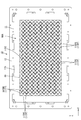
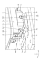
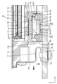
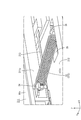
- a perspective view of an input device according to Embodiment 1 of the present invention An exploded perspective view of the input device Top view of input device Side view of input device Front view of input device Top view of the base member provided in the input device The perspective view which expanded the elastic member vicinity with which an input device is equipped The elastic member provided in the input device, the pressure sensor unit and the side view in which the vicinity of the actuator is enlarged
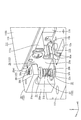
- the perspective view of the input device concerning Embodiment 2 of the present invention Side view of input device Front view of input device
- the perspective view which expanded the position adjustment mechanism vicinity with which an input device is equipped Side cross-sectional view in which the vicinity of the position adjustment mechanism provided in the input device is enlarged
- the perspective view of the input device concerning Embodiment 3 of the present invention Side view of input device Front view of input device
- Embodiment 1 of the present invention will be described with reference to FIGS.
- an input device 10 having a tactile feedback function (tactile feedback function) will be described.
- X-axis, Y-axis, and Z-axis are shown in a part of each drawing, and it is drawn so that each axis direction may turn into the direction shown in each drawing.
- the upper side of each figure is the front side and the lower side of each figure is the rear side, with reference to FIGS. 4, 5, 8, 10, and 11.
- the input device 10 includes a liquid crystal display (input receiving member) 11 for displaying an image and inputting a pressing operation by the user, and a base member 12 to which the liquid crystal display 11 is attached. At least equipped. Among them, the liquid crystal display device 11 has a touch panel function (position input function) for detecting a pressed position (input position) by the user, in addition to a display function for displaying an image.
- the input device 10 used for the car navigation system mounted in a passenger car is illustrated, a specific use can be suitably changed besides it.
- the liquid crystal display device 11 is disposed on the liquid crystal panel (display panel) 11a on which an image is displayed, and on the back side (the opposite side to the input side of pressing operation) with respect to the liquid crystal panel 11a.
- the liquid crystal panel 11a is substantially transparent, for example, made of glass, and a pair of substrates bonded to each other with their inner surfaces facing each other with a predetermined gap (cell gap) therebetween, and a liquid crystal sealed between the two substrates. At least a layer and a pair of polarizing plates (both the substrate and the liquid crystal layer not shown) disposed on the outer surface of both substrates.
- a color filter in which colored portions such as R (red), G (green), B (blue) and the like are arranged in a predetermined array on a CF substrate (opposing substrate) disposed on the front side.
- a structure such as an alignment film is provided.
- switching elements for example, TFTs
- source wiring and gate wiring orthogonal to each other switching elements connected to source wiring and gate wiring orthogonal to each other, pixel electrodes connected to the switching elements, alignment films, etc.
- a structure is provided.
- the liquid crystal panel 11a is in the form of a horizontally long square in plan view
- the display surface 11DS is a frame shape surrounding the display area (active area) AA where the image is displayed and the display area AA. It is divided into a non-display area (non-active area) NAA forming a (frame shape).
- the long side direction of the liquid crystal panel 11a is the X axis direction of each figure
- the short side direction of the liquid crystal panel 11a is the Y axis direction of each figure
- the normal direction of the display surface 11DS is the Z axis direction of each figure. I do.
- the alternate long and short dash line represents the outer shape of the display area AA, and the area outside the alternate long and short dash line is the non-display area NAA.
- the liquid crystal panel 11a incorporates a touch panel pattern 11TP for detecting a pressing position at which the user performs a pressing operation.
- the touch panel pattern 11TP is a so-called projected capacitive type, and its detection type is, for example, a self-capacitive type.
- the touch panel pattern 11TP at least includes a plurality of touch electrodes (position detection electrodes) 11TPE arranged in a matrix in the display area AA.
- the display area AA in the liquid crystal panel 11a substantially coincides with the touch area where the pressed position can be detected, and the non-display area NAA substantially coincides with the non-touch area where the pressed position can not be detected.
- a capacitance is formed between the finger and the touch electrode 11TPE.
- the capacitance detected by the touch electrode 11TPE near the finger is changed as the finger approaches and becomes different from the touch electrode 11TPE far from the finger, so that based on that It is possible to detect the pressing position.
- the cover glass 11b has a horizontally long rectangular shape that is slightly larger than the liquid crystal panel 11a, and covers the liquid crystal panel 11a from the front side to cover almost the entire area.
- the cover glass 11b is made of a substantially transparent and excellent light transmitting glass and has a plate shape, and is preferably made of tempered glass.
- the tempered glass used for the cover glass 11b for example, it is preferable to use a chemically strengthened glass having a chemically strengthened layer on the surface by subjecting the surface of a plate-like glass substrate to a chemical strengthening treatment. Not as long.
- the housing 11c has a substantially box shape opened to the front side, and has a housing space for housing the liquid crystal panel 11a and the backlight device 11d inside.
- the base member 12 is formed of a rectangular plate having a horizontally long planar shape, and is fixed to a base block BB installed on a dashboard (not shown) of a passenger car.
- the base block BB is disposed in a pair so as to overlap with the pair of short sides of the outer peripheral end of the base member 12, and is provided so as to project outward from the installation surface of the dashboard.
- the base member 12 is one size larger than that of the liquid crystal display device 11 in plan view, and various components (such as the pressure sensor 13, the actuator 14 and the elastic member 15 described below) are attached to the plate surface Holes (screw holes) and the like are provided.
- the base block BB as described above is not necessary.
- the base member 12 includes a pressure sensor (pressure sensor) 13 for detecting a pressure acting on the liquid crystal display device 11 in response to the pressing operation, and an actuator 14 for vibrating the liquid crystal display device 11.
- a pressure sensor pressure sensor
- an actuator 14 for vibrating the liquid crystal display device 11.
- At least an elastic member 15 elastically supporting the liquid crystal display device 11 relative to the base member 12 in a relatively displaceable state is attached. Between the liquid crystal display device 11 supported by the elastic member 15 and the base member 12, a predetermined space is provided in the Z-axis direction.
- the pressure sensor 13 is a so-called pressure-sensitive ink type, as shown in FIGS.
- the pressure sensor 13 has at least a pair of films bonded to each other and made of an insulating material, and pressure-sensitive electrodes (films not shown) formed on the inner surfaces of the respective films and arranged to face each other.
- the pressure is detected by utilizing the fact that the contact resistance value between the pair of pressure-sensitive electrodes facing each other changes according to the pressure acting on the pressure sensor 13 in the thickness direction (Z-axis direction). It is possible to do
- the pressure sensitive electrode is formed by printing a pressure sensitive ink on a film.
- the pressure sensor 13 extends in a strip shape along the X-axis direction, and one end thereof is built in the pressure sensor unit 16 attached to the base member 12 and has a substantially circular planar shape, while the other end is The side is drawn out of the pressure sensor unit 16 and connected to a controller (the connectors are not shown) via a connector.
- the pressure sensor unit 16 will be described in detail later.
- the pressure sensors 13 are disposed near the four corners of the liquid crystal display device 11 and the base member 12 along with the pressure sensor unit 16.
- the actuator 14 is a so-called electromagnetic actuator (solenoid actuator), and a fixing portion 14a attached to the base member 12 and an attachment portion 14a attached to the liquid crystal display device 11 And a movable portion 14b which is relatively displaceable in the X-axis direction (vibration direction).
- the fixed portion 14a includes at least a fixed magnetic pole and a coil wound around the fixed magnetic pole, although not shown in the drawings, whereas the movable portion 14b has a movable magnetic pole that can be displaced relative to the fixed magnetic pole. (Not shown) at least.
- the actuator 14 can move the movable portion 14b relative to the fixed portion 14a along the X-axis direction by attracting the movable magnetic pole by the magnetic field generated in the fixed magnetic pole as the coil is energized. It is assumed. Thus, the liquid crystal display device 11 having the movable portion 14b attached to the base member 12 to which the fixed portion 14a is attached can be vibrated along the X-axis direction (direction orthogonal to the pressing direction of the pressing operation). .
- the fixing portion 14 a of the actuator 14 is fixed to the base member 12 by a screw member.
- the movable portion 14b of the actuator 14 is fixed by a screw member to a leaf spring member 18 extending along the X-axis direction.
- the plate spring member 18 is formed of a flat plate made of metal (for example, stainless steel), and the plate surface is parallel to the display surface 11DS of the liquid crystal display device 11 and the plate surface of the base member 12. It can be elastically deformed in the Z-axis direction (pressing direction) which is the normal direction.
- the plate spring member 18 is fixed by a screw member to the block-like movable side bracket 19 whose one end side in the X-axis direction is fixed to the movable portion 14b described above and the other end side is fixed to the housing 11c of the liquid crystal display device 11 ing.
- the leaf spring member 18 can be elastically deformed in a cantilever shape with one end fixed to the movable portion 14b as a fulcrum, and the other end can be relatively displaced along the Z-axis direction in accordance with the elastic deformation. Ru. Further, in the plate spring member 18, an opening 18a is formed at an intermediate portion between the movable portion 14b and the both end portions fixed to the movable side bracket 19, whereby the intermediate portion forms a pair of belts. ing. Since the liquid crystal display device 11 is fixed to the other end side of the plate spring member 18 via the movable side bracket 19, the liquid crystal display device 11 is relatively displaced in the Z-axis direction with elastic deformation of the plate spring member 18. It is made possible.
- the actuators 14 are pressure sensors 13 and pressure sensor units 16 which are respectively disposed in the vicinity of the four corners of the liquid crystal display 11 as described above in the base member 12.
- the liquid crystal display device 11 is disposed on the inner side (central side).
- the pair of actuators 14 are arranged side by side at intervals in the Y-axis direction.
- the pair of actuators 14 are aligned in the X-axis direction, and the other end side of the pair of plate spring members 18 fixed to the pair of movable portions 14 b spans the pair of plate spring members 18.
- the common movable side bracket 19 extending along the Y-axis direction is fixed.
- the pair of actuators 14 is disposed in the plate surface of the base member 12 so as to be sandwiched between the pair of pressure sensor units 16 shown in FIG. 5 in the short side direction (Y axis direction) in the liquid crystal display device 11 At the same time, the liquid crystal display device 11 is disposed at a position adjacent to the center side with respect to the pressure sensor 13 on the left side shown in FIG. 4 in the long side direction (X-axis direction). Therefore, it can be said that the pair of actuators 14 is arranged so as to be surrounded by the four pressure sensors 13 and the pressure sensor unit 16 (elastic member 15) disposed near the four corners of the liquid crystal display device 11.
- the pair of actuators 14 is disposed in the X axis direction so that the movable side bracket 19 fixed to the other end side of the plate spring member 18 is attached at a substantially central position in the X axis direction in the liquid crystal display device 11 . Therefore, the vibration in the X-axis direction generated in the movable portion 14 b with the oscillation of the pair of actuators 14 is transmitted to the approximate center position of the display surface 11 DS in the liquid crystal display device 11 via the plate spring member 18 and the movable side bracket 19. It will be done.
- the elastic member 15 is formed by pressing a metal plate material or the like, and as shown in FIG. 1, the liquid crystal display device 11 is supported at a position away from the base member 12 in the Z axis direction. It is supposed to be. As shown in FIGS. 7 and 11, the elastic member 15 is connected to a pair of first spring portions 15a extending substantially along the Z-axis direction (pressing direction) and a pair of first spring portions 15a. And a second spring portion 15b which is bent while extending along the X-axis direction (direction intersecting the pressing direction).
- the pair of first spring portions 15a includes one that is disposed on the front side in the Z-axis direction and one end is attached to the liquid crystal display device 11, and one that is disposed on the back side and one end is attached to the base member 12.
- the first spring portion 15 a on the front side has a wide end shape on one end side, and is fixed to the outer side surface of the case 11 c of the liquid crystal display device 11 by two screw members.
- the first spring portion 15a on the back side is bent parallel to the back surface of the base member 12 when the one end side reaches the back surface side of the base member 12 through the hole 12a formed in the base member 12 and the parallel portion is bent It is fixed to the base member 12 by a screw member.
- the first spring portion 15a on the back side is disposed so as to penetrate the base member 12, it is possible to temporarily use only the space between the liquid crystal display device 11 and the base member 12 for the elastic member. As compared with the case where they are disposed, the extending surface distance of the elastic member 15 becomes longer by about the thickness dimension of the base member 12.
- the pair of first spring portions 15a can be elastically deformed in a cantilever shape in the X-axis direction (the vibration direction) with the mounting position with respect to the liquid crystal display device 11 or the base member 12 as a fulcrum.
- the second spring portion 15b has a shape in which the "U" character is turned down when viewed from the side, and both end portions thereof are connected to the other end sides of the pair of first spring portions 15a.
- the second spring portion 15b is bent in a curved shape while extending toward the inner side (central side) of the liquid crystal display device 11 along the X-axis direction from a position connected to the pair of first spring portions 15a.
- the second spring portion 15 b is elastically deformable in the Z-axis direction with the curved bending portion as a fulcrum.
- the elastic member 15 is elastically deformable in both the X-axis direction and the Z-axis direction, whereby the liquid crystal display device 11 is elastically relative to the base member 12 in the X-axis direction and the Z-axis direction. It supports in a displaceable form.
- each of the four elastic members 15 is disposed in such a manner that the second spring portion 15 b protrudes inward with respect to the first spring portion 15 a, in other words, in a manner to approach the pressure sensor 13 and the pressure sensor unit 16.
- the input device 10 is, as shown in FIGS. 9 to 11, a braking member 20 disposed in contact with the liquid crystal display device 11 and a braking member 20 disposed on the base member 12 side. And a position adjustment mechanism 22 for adjusting the position of at least one of the liquid crystal display device 11 and the holding member 21 in the pressing direction.
- the braking member 20, the holding member 21 and the position adjusting mechanism 22 are integrally provided in the pressure sensor unit 16 having the configuration described below.
- the liquid crystal display device 11 is illustrated by a two-dot chain line.
- the pressure sensor unit 16 holds the braking member 20 in direct contact with the liquid crystal display device 11, the holding member 21 holding the braking member 20, the pressure sensor 13, and the sensor holding the pressure sensor 13.
- a holding member (sensor holder) 23, a position adjustment spacer 24 superimposed on the back side with respect to the sensor holding member 23, a case 25 for accommodating these members, and a position adjustment screw 26 for moving the position adjustment spacer 24 Prepare.
- the sensor holding member 23, the position adjustment spacer 24 and the position adjustment screw 26 constitute a position adjustment mechanism 22.
- four pressure sensor units 16 are disposed near the four corners of the liquid crystal display device 11 and the base member 12, and the liquid crystal display device in the X axis direction with respect to the four elastic members 15. 11 and the base member 12 are arranged adjacent to each other.
- the braking member 20 is in the form of a sheet having a rectangular planar shape and a predetermined thickness.
- the braking member 20 is made of a high friction material (woven friction material, mold friction material, etc.), and a holding member 21 (a member interposed between the liquid crystal display device 11 and the pressure sensor 13) whose friction coefficient is described next Higher than the coefficient of friction of
- the holding member 21 includes a main portion 21a interposed between the braking member 20 and the pressure sensor 13, and a cylindrical portion 21b projecting from the outer peripheral end of the main portion 21a toward the back side, and as a whole, the case 25 It is in the form of a cap to be put on.
- a braking member housing recess 21c for housing the braking member 20 is formed in a recessed manner on the front surface of the main portion 21a of the holding member 21 (the surface facing the liquid crystal display device 11 and the braking member 20).
- a sensor contact convex portion 21d that is in contact with the pressure sensor 13 protrudes toward the back side. It is formed in the form of
- the main portion 21 a of the holding member 21 supports the braking member 20 from the back side, holds the pressure sensor 13 from the front side, and is disposed so as to be sandwiched between the braking member 20 and the pressure sensor 13 in the Z axis direction. .
- the cylindrical portion 21 b of the holding member 21 has a rectangular cylindrical shape, and is disposed so as to surround the case 25 from the outer peripheral side.
- a notch 21b1 for passing the pressure sensor 13 and the position adjustment screw 26 is formed in the cylindrical portion 21b.
- the notches 21b1 are respectively provided on the four sides forming the cylindrical portion 21b.
- the sensor holding member 23 has a rectangular plate shape in plan view, and is housed in the case 25 so as to be interposed between the pressure sensor 13 and the position adjustment spacer 24 described next. ing.
- a sensor housing recess 23 a for housing the pressure sensor 13 is formed in a recessed manner on the front surface of the sensor holding member 23 (the surface facing the pressure sensor 13 and the holding member 21).
- a convex portion 23b is provided which protrudes toward the back side along the Z-axis direction.
- a first inclined surface 23c that is inclined with respect to both the Z-axis direction and the Y-axis direction is formed on the protruding end surface (surface on the back side) of the convex portion 23b.
- the first inclined surface 23c has a slope (upward slope) approaching the pressure sensor 13 in the Z-axis direction from the opposite side to the position adjustment screw 26 described later in the Y-axis direction toward the position adjustment screw 26 It is linear.
- the position adjustment spacer 24 has a rectangular plate shape in plan view, and is accommodated in the case 25 so as to overlap the sensor holding member 23 on the back side.
- the outer shape of the position adjustment spacer 24 is smaller than the outer shape of the sensor holding member 23 by one turn, and is substantially the same as the outer shape of the convex portion 23 b.
- the position adjustment spacer 24 has a substantially flat surface on the back side, while the surface on the front side (the surface facing the sensor holding member 23) is inclined with respect to both the Z axis direction and the Y axis direction. Two inclined surfaces 24a are formed. As shown in FIG.
- the second inclined surface 24a is parallel to the first inclined surface 23c described above, and extends from the position adjustment screw 26 side to the opposite side to the position adjustment screw 26 side in the Y-axis direction. It has a linear shape so as to have a gradient (downward gradient) away from the pressure sensor 13 in the axial direction.
- the first inclined surface 23c and the second inclined surface 24a are in contact with each other, and are accommodated in the sensor accommodation recess 23a and there.
- the pressure sensor 13 is kept substantially horizontal.
- the side surface on the side of the position adjustment screw 26 in the Y axis direction has a wider formation range in the Z axis direction than the side surface on the opposite side to the position adjustment screw 26 side
- the screw contact surface 24 b is abutted against the tip end surface 26.
- the case 25 has a substantially box shape opening toward the front side, and the position adjustment spacer 24, the sensor holding member 23 and the pressure sensor 13 are accommodated in an overlapping manner in the inside thereof.
- a housing recess 25a is formed.
- the housing recess 25a has a step shape having two bottoms of different heights, and the position adjustment spacer 24 is relatively low at the relatively low bottom, and the sensor holding member 23 is relatively high at the relatively high bottom, from the back side.
- the housing recess 25a is larger in size in the Y-axis direction than the position adjustment spacer 24, so that the position adjustment spacer 24 can be displaced relative to the case 25 in the Y-axis direction. As shown in FIGS.
- a pair of notches 25b communicating with a part of the four notches 21b1 provided in the holding member 21 is formed in a part of the outer peripheral side wall in the case 25.
- the other end side of the pressure sensor 13 can be pulled out through the notches 21b1 and 25b communicating with each other.
- a screw insertion hole 25c for passing the position adjustment screw 26 is formed through a portion of the outer peripheral side wall of the case 25 where the notch 25b is not formed. .
- the screw insertion hole 25c is disposed to face the screw contact surface 24b of the position adjustment spacer 24 housed in the housing recess 25a.
- the position adjusting screw 26 has, as shown in FIGS. 9 and 10, a shaft portion 26a having an axis parallel to the Y-axis direction, and a head portion 26b provided on one end side of the shaft portion 26a.
- a screw thread (not shown) is formed on the outer peripheral surface of the shaft portion 26a.
- the position adjusting screw 26 is passed through the screw insertion hole 25c of the case 25 and tightened, thereby advancing to the left side shown in FIG. 10 along the Y axis direction which is the axial direction of the shaft portion 26a, and reversely When loosened, it retracts toward the right side shown in FIG. 10 along the Y-axis direction.
- the position adjusting spacer 24 slides (moves) to the left side shown in FIG. 10 along the Y-axis direction, so the second inclined surface 24a to the first inclined surface 23c of the sensor holding member 23
- the force acts upward in the Z-axis direction, that is, in a direction approaching the liquid crystal display device 11.
- the sensor holding member 23 and the holding member 21 can be displaced relative to the liquid crystal display device 11 so as to approach in the Z-axis direction.
- a downward force acting along the Z-axis direction from the sensor holding member 23 side to the position adjustment spacer 24 side is converted by the first inclined surface 23c and the second inclined surface 24a.
- the position adjustment spacer 24 slides to the right in FIG. 10 along the Y-axis direction, and as a result, the sensor holding member 23 and the holding member 21 move downward in the Z-axis direction, that is, away from the liquid crystal display device 11. Relative displacement. As described above, by operating the position adjustment screw 26, it is possible to adjust the position of the holding member 21 with respect to the liquid crystal display device 11 in the Z-axis direction.
- the present embodiment is configured as described above, and its operation will be described subsequently.
- the user inputs a pressing operation into the surface of the display surface 11DS of the liquid crystal display device 11 by pressing the surface of the cover glass 11b with a finger, as shown in FIGS. 7 and 8, the liquid crystal display device 11 and the base member 12
- the second spring portion 15b of the elastic member 15 attached to the is elastically deformed in the Z axis direction which is the pressing direction of the pressing operation, whereby the Z axis direction (pressing direction) of the liquid crystal display device 11 with respect to the base member 12 is Relative displacement is allowed.
- the pressure sensor 13 built in the pressure sensor unit 16 attached to the base member 12 is, as shown in FIG.
- the pressure applied by the liquid crystal display device 11 can be appropriately detected because the sensor contact convex portion 21 d presses the sensor contact displacement by being displaced downward.
- the liquid crystal display device 11 and the holding member 21 hardly displace in the Z-axis direction. Is not detected or the detected pressure does not exceed the threshold value, so that erroneous input can be appropriately eliminated.
- the touch panel pattern 11TP provided on the liquid crystal panel 11a included in the liquid crystal display device 11 can detect the input position.
- FIG. 8 the direction in which the elastic member 15 elastically deforms with the pressing operation is illustrated by the downward arrow in the vicinity of the elastic member 15.
- the movable portion 14 b of each actuator 14 is As shown in FIG. 8, the other end side of the plate spring member 18 attached to the liquid crystal display device 11 via the movable side bracket 19 is displaced toward the back side in the Z-axis direction, as shown in FIG. 8. At this time, the plate spring member 18 can be elastically deformed in a cantilever shape in the Z-axis direction with one end side as a fulcrum, so that the stress acting on each actuator 14 can be relieved. In FIG. 8, the direction in which the plate spring member 18 elastically deforms with the pressing operation is illustrated by the downward arrow in the vicinity of the movable side bracket 19.
- each actuator 14 is determined based on the determination. Is oscillated.
- the oscillation of each actuator 14 can be appropriately controlled based on the input position of the pressing operation detected by the touch panel pattern 11TP.
- each first spring portion 15 a of the elastic member 15 attached to the liquid crystal display device 11 and the base member 12 is the vibration direction of each actuator 14 By being elastically deformed in the X axis direction, relative displacement in the X axis direction of the liquid crystal display device 11 with respect to the base member 12 is allowed.
- each actuator 14 the movable portion 14 b attached to the liquid crystal display device 11 is displaced relative to the fixed portion 14 a attached to the base member 12 in the X axis direction.
- the display device 11 is vibrated with respect to the base member 12 in the X-axis direction.
- the liquid crystal display device 11 is vibrated in the X axis direction which is a direction orthogonal to the pressing direction with respect to the base member 12, and the vibration is transmitted to the finger (input body) of the user who input the pressing operation. be able to.
- the vibration of the liquid crystal display device 11 if it is difficult for the vibration of the liquid crystal display device 11 to converge, it is easily perceived that the user's finger is simply vibrating in the X axis direction (direction orthogonal to the pressing direction). For example, it may be difficult to perceive a tactile sense as if pressed in the Z-axis direction (pressing direction).
- the holding member 21 provided in the pressure sensor unit 16 attached to the base member 12 holds the braking member 20 disposed in contact with the liquid crystal display device 11.
- the liquid crystal display device 11 vibrating along the X-axis direction can be braked by the braking member 20.
- the position adjustment mechanism 22 by adjusting the position of the holding member 21 with respect to the liquid crystal display device 11 with respect to the liquid crystal display device 11 by the position adjustment mechanism 22, it is possible to adjust the contact state of the braking member 20 with respect to the liquid crystal display device 11.
- the braking force of the braking member 20 acting on the liquid crystal display device 11 vibrating with respect to the base member 12 can be controlled, so that the vibration of the liquid crystal display device 11 can be appropriately converged. Therefore, it is easy for the user's finger to which the vibration is transmitted through the liquid crystal display device 11 to obtain a tactile sensation as if a virtual button is pressed in the Z-axis direction on the display surface 11DS due to the lateral force field phenomenon. .
- the liquid crystal display device 11 is vibrated to achieve good tactile feedback for the pressing operation. Can be done.
- the pair of actuators 14 for applying vibration to the liquid crystal display device 11 is an electromagnetic actuator having the fixed portion 14a and the movable portion 14b, for example, stronger vibration is obtained compared to an inertial drive actuator or the like. It is more suitable for realizing tactile feedback.
- FIG. 8 and FIG. 11 the direction in which the elastic member 15 elastically deforms with the oscillation of the actuator 14 and the direction in which the liquid crystal display device 11 vibrates are respectively shown by arrows pointing left.
- the pressure sensor 13 is disposed in such a manner that the braking member 20 and the holding member 21 are interposed between the pressure sensor 13 and the liquid crystal display device 11. Is input, the pressure acting on the liquid crystal display device 11 is detected by being transmitted to the pressure sensor 13 via the braking member 20 and the holding member 21.
- the position adjusting mechanism 22 adjusts the position of the holding member 21 with respect to the liquid crystal display device 11 in the Z-axis direction, the contact state of the liquid crystal display device 11 with respect to the braking member 20 is adjusted.
- the positional relationship of the member 21 in the Z-axis direction is adjusted.
- the position adjustment mechanism 22 adjusts the position of the holding member 21 in the Z-axis direction via the pressure sensor 13 and the sensor holding member 23 that holds the pressure sensor 13 from the side opposite to the holding member 21 side.
- the holding member 21 holding the braking member 20 is position-adjusted in the Z-axis direction by the position adjusting mechanism 22 via the pressure sensor 13 and the sensor holding member 23, whereby the liquid crystal display device 11 is The contact state of the braking member 20 is adjusted.
- the contact state of the pressure sensor 13 with respect to the holding member 21 is also collectively adjusted, it is possible to temporarily compare the contact state of the braking member 20 and the contact state of the pressure sensor 13 as compared to the case. Workability concerning adjustment becomes good.
- the four elastic members 15 and the pressure sensor unit 16 are respectively disposed near the four corners of the liquid crystal display device 11. Therefore, the liquid crystal for the base member 12 accompanying the pressing operation While the relative displacement in the Z-axis direction of the display device 11 is allowed smoothly, the pressure acting on the liquid crystal display device 11 with the pressing operation is appropriately detected.
- the pair of actuators 14 is disposed on the inner side of the liquid crystal display device 11 compared to the braking members 20 and the holding members 21 provided in the four pressure sensor units 16 disposed near the four corners in the liquid crystal display device 11 Therefore, the whole of the liquid crystal display device 11 can be appropriately vibrated, and the vibration of the liquid crystal display device 11 can be more appropriately converged by the braking members 20 respectively contacting the four corners of the liquid crystal display device 11.
- the other end side of the plate spring member 18 whose one end side is attached to the movable portion 14 b of each actuator 14 is the movable side bracket 19 fixed at the center position in the X axis direction and Y axis direction in the liquid crystal display device 11. Because the liquid crystal display device 11 is attached, the entire liquid crystal display device 11 can be vibrated most satisfactorily.
- the input device 10 includes the liquid crystal display device (input receiving member) 11 to which the pressing operation is input, the base member 12 to which the liquid crystal display device 11 is attached, and at least the liquid crystal display device 11 side.
- the actuator 14 is disposed to vibrate the liquid crystal display device 11 in a direction perpendicular to the pressing direction of the pressing operation, the braking member 20 disposed in contact with the liquid crystal display device 11, and the base member 12 side
- a holding member 21 for holding the braking member 20 and a position adjustment mechanism 22 for adjusting the position of at least one of the liquid crystal display device 11 and the holding member 21 in the pressing direction are provided.
- the liquid crystal display device 11 when the actuator 14 is oscillated as the pressing operation is input to the liquid crystal display device 11, the liquid crystal display device 11 is vibrated in the direction orthogonal to the pressing direction with respect to the base member 12. The vibration can be transmitted to the input body to which the pressing operation is input. At this time, if it is difficult for the vibration of the liquid crystal display device 11 to converge, the input body is easily perceived as vibrating in the direction orthogonal to the pressing direction, for example, the pressing is performed in the pressing direction Such sense of touch may be difficult to perceive.
- the damping member 20 disposed in contact with the liquid crystal display device 11 is held by the holding member 21 disposed on the base member 12 side, the liquid crystal display device vibrates relative to the base member 12 11 can be braked by the braking member 20.
- the position adjustment mechanism 22 can adjust the position of at least one of the liquid crystal display device 11 and the holding member 21 in the pressing direction, the contact state of the braking member 20 with respect to the liquid crystal display device 11 can be adjusted. ing.
- the braking force of the braking member 20 acting on the liquid crystal display device 11 vibrating with respect to the base member 12 can be controlled, so that the vibration of the liquid crystal display device 11 can be appropriately converged. Therefore, in the input body to which the vibration is transmitted through the liquid crystal display device 11, for example, a tactile sense as if pressed in a pressing direction is easily perceived, and tactile feedback can be performed favorably.
- the pressure sensor 13 is disposed on the base member 12 and detects a pressure acting on the liquid crystal display device 11 in accordance with the pressing operation. In this way, when a pressing operation is input to the liquid crystal display device 11, the pressure acting on the liquid crystal display device 11 is detected by the pressure sensor 13.
- the actuator 14 is oscillated based on the pressure detected by the pressure sensor 13, whereby the liquid crystal display device 11 is oscillated, whereby the oscillation can be transmitted to the input body to which the pressing operation is input.
- the liquid crystal display device 11 and the base member 12 are provided with an elastic member 15 elastically deformable in both the pressing direction and the vibration direction of the actuator 14.
- the elastic member 15 attached to the liquid crystal display device 11 and the base member 12 is elastically deformed in the pressing direction of the pressing operation, whereby the base member The relative displacement in the pressing direction of the liquid crystal display device 11 with respect to 12 is allowed.
- the pressure acting on the liquid crystal display device 11 can be appropriately detected by the pressure sensor 13, and erroneous input can be appropriately eliminated.
- the elastic member 15 attached to the liquid crystal display device 11 and the base member 12 is elastically deformed in the vibration direction of the actuator 14 so that the vibration direction of the liquid crystal display device 11 with respect to the base member 12 is Relative displacement is allowed.
- the elastic member 15 extends along the pressing direction and one end side is attached to the pair of first spring portions 15a attached to the liquid crystal display device 11 or the base member 12, and the other end side of the pair of first spring portions 15a. And a second spring portion 15b connected and bent while extending in a direction crossing the pressing direction.
- the second spring portion 15b of the elastic member 15 which is bent while extending along the direction intersecting the pressing direction is pressed by the pressing operation. It is elastically deformed in the direction.
- the pair of first spring portions 15 a of the elastic member 15 extending along the pressing direction is elastically deformed in the vibration direction of the actuator 14.
- the pressure sensor 13 is disposed such that the braking member 20 and the holding member 21 are interposed between the pressure sensor 13 and the liquid crystal display device 11. In this way, when a pressing operation is input to the liquid crystal display device 11, the pressure acting on the liquid crystal display device 11 is detected by being transmitted to the pressure sensor 13 via the braking member 20 and the holding member 21. Ru.
- the contact state of the liquid crystal display device 11 with respect to the braking member 20 is adjusted.
- the positional relationship in the pressing direction of the member 21 is adjusted.
- the sensor holding member 23 holds the pressure sensor 13 from the side opposite to the holding member 21.
- the position adjustment mechanism 22 presses the holding member 21 via the pressure sensor 13 and the sensor holding member 23 in the pressing direction. Adjust the position. In this way, the holding member 21 holding the braking member 20 is adjusted in position in the pressing direction by the position adjusting mechanism 22 via the pressure sensor 13 and the sensor holding member 23, whereby the braking member 20 for the liquid crystal display device 11 is The contact state of is adjusted. At this time, since the contact state of the pressure sensor 13 with respect to the holding member 21 is also adjusted, the workability relating to the adjustment becomes good.
- the actuator 14 is an electromagnetic actuator having a fixed portion 14a attached to the base member 12 and a movable portion 14b attached to the liquid crystal display device 11 and capable of relative displacement with respect to the fixed portion 14a in the vibration direction. Be done. In this way, the movable portion 14b attached to the liquid crystal display device 11 is displaced relative to the fixed portion 14a attached to the base member 12 with respect to the vibration direction, whereby the liquid crystal display device 11 relative to the base member 12 is moved. It can be vibrated.
- the actuator 14 as the electromagnetic actuator having the fixed portion 14a and the movable portion 14b as described above, for example, a stronger vibration can be obtained as compared with, for example, an inertial drive actuator, thereby realizing haptic feedback. It becomes more preferable.
- the liquid crystal display device 11 has a rectangular planar shape
- the braking member 20 and the holding member 21 are respectively disposed at the four corners in the liquid crystal display device 11, and the actuator 14 is compared with the braking member 20 and the holding member 21. Is disposed inside the liquid crystal display device 11.
- the actuator 14 is disposed inside the liquid crystal display device 11 with respect to the braking member 20 and the holding member 21 disposed at the four corners of the liquid crystal display device 11 having a rectangular planar shape. While being able to vibrate the whole liquid crystal display device 11 appropriately with oscillation of 14, and making the vibration of the liquid crystal display device 11 converge more appropriately by the damping member 20 which contacts the four corners of the liquid crystal display device 11, respectively. it can.
- the liquid crystal display device 11 also includes a liquid crystal panel (display panel) 11a having a display surface 11DS for displaying an image, and a touch panel pattern 11TP for detecting an input position of a pressing operation on the display surface 11DS.
- a liquid crystal panel display panel
- a touch panel pattern 11TP for detecting an input position of a pressing operation on the display surface 11DS.
- Second Embodiment Second Embodiment A second embodiment of the present invention will be described with reference to FIGS.
- the position adjustment mechanism 122 is modified.
- action, and an effect is abbreviate
- the position adjustment mechanism 122 which concerns on this embodiment is separately provided from the pressure sensor unit 116, as shown to FIGS. 12-14.
- the four position adjustment mechanisms 122 are disposed adjacent to the outside in the X-axis direction with respect to the four corner portions of the liquid crystal display device 111 and the four elastic members 115. A part of the four position adjustment mechanisms 122 is disposed outside with respect to the liquid crystal display device 111 in the Y-axis direction.
- the position adjustment mechanism 122 is, as shown in FIGS. 15 and 16, a compression coil spring (coil spring) 27, a first coil spring holding member 28 attached to the base member 112 and holding the compression coil spring 27, and liquid crystal It has at least a second coil spring holding member 29 attached to the display device 111 and holding the compression coil spring 27, and a spring force adjustment member 30 applying compression force to the compression coil spring 27.
- the compression coil spring 27 is held in a posture in which the axial direction coincides with the Z-axis direction (pressing direction), and is compressed along the axial direction from the natural state, whereby an elastic force (restoring force in the axial direction is obtained). ) Is accumulated.
- the compression coil spring 27 is disposed adjacent to the outside in the Y axis direction with respect to the elastic member 115 (FIG. 14).
- the first coil spring holding member 28 has a block shape and is attached to the base member 112 along the Y axis direction from the base attachment portion 28 a and the base attachment portion 28 a. And a first spring-side mounting portion 28b to which the compression coil spring 27 is attached.
- the first spring mounting member 31 mounted on one end side of the compression coil spring 27 and the spring force adjustment member 30 are mounted on the first spring side mounting portion 28b in such a manner that relative displacement is possible in the Z axis direction (pressing direction).
- Be The first spring mounting member 31 is fitted into one end of the compression coil spring 27 and forms a substantially cylindrical first shaft 31a coaxial with the compression coil spring 27, and an end of the first shaft 31a.
- the second coil spring holding member 29 is substantially L-shaped as viewed from the side, and is provided with a housing side mounting portion 29a attached to the housing 111c of the liquid crystal display device 111, and a base member 112 in the housing side mounting portion 29a. And a second spring-side mounting portion 29b to which the compression coil spring 27 is attached so as to protrude outward along the X-axis direction from the end of the side.
- the second spring side attachment portion 29 b receives the other end of the compression coil spring 27 from the outside in the Z-axis direction.
- the second spring mounting member 32 mounted on the other end side of the compression coil spring 27 is mounted to the second spring side mounting portion 29b in a manner such that relative displacement is not possible in the Z-axis direction.
- the second spring mounting member 32 is fitted inside the other end of the compression coil spring 27 and forms a substantially cylindrical second shaft 32a coaxial with the compression coil spring 27, and an end of the second shaft 32a.
- a second receiving portion 32b that protrudes like a bowl and receives the second spring side mounting portion 29b from the outside in the Z-axis direction.
- the spring force adjustment member 30, as shown in FIGS. 15 and 16, has a substantially cylindrical shape coaxial with the compression coil spring 27, and penetrates the first spring side attachment portion 28b of the first coil spring holding member 28.
- the tip end face of the hole 28 b 1 is in contact with the first spring mounting member 31.
- a screw thread (not shown) is screwed on the outer peripheral surface of the spring force adjustment member 30, and the screw thread is screwed into a screw groove screwed on the inner peripheral surface of the hole 28b1.
- an operation recess 30a that can be operated by a tool such as a hexagonal wrench is recessed.
- the spring force adjusting member 30 can be advanced and retracted along the Z-axis direction by rotating the tool inserted into the operation recess 30a, and accordingly, the first spring mounting member 31 is advanced and retracted along the Z-axis direction Then, the compression state of the compression coil spring 27 can be changed. Specifically, when the spring force adjustment member 30 is tightened, the first spring mounting member 31 approaches the base member 112 in the Z-axis direction, and the amount of compression of the compression coil spring 27 increases accordingly. When the amount of compression of the compression coil spring 27 increases, the liquid crystal display device 111 moves relative to the base member 112 in the Z-axis direction (relatively displaces to the lower side shown in FIG. Is taken.
- the first spring mounting member 31 moves away from the base member 112 in the Z-axis direction, and the amount of compression of the compression coil spring 27 decreases accordingly. If the amount of compression of the compression coil spring 27 decreases, the liquid crystal display device 111 is displaced relative to the base member 112 in the Z-axis direction (relatively displaced upward as shown in FIG. 16), thereby adjusting the position.
- the position of the liquid crystal display device 111 can be adjusted in the Z-axis direction with respect to the holding member 121 disposed on the base member 112 side, and the contact state of the braking member 120 with respect to the liquid crystal display device 111 can be adjusted. it can.
- the pressure sensor unit 116 since the pressure sensor unit 116 according to the present embodiment does not incorporate the above-described position adjusting mechanism 122, the pressure sensor unit 116 includes the position adjusting spacer 24 described in the above-described first embodiment. Accordingly, the sensor holding member 123 has a block shape that fills the internal space of the housing recess 125a of the case 125, and does not have the first inclined surface 23c described in the first embodiment.
- the position adjustment mechanism 122 includes the compression coil spring (coil spring) 27 and the first coil spring holding member 28 attached to the base member 112 and holding the compression coil spring 27.
- the second coil spring holding member 29 attached to the liquid crystal display device 111 and holding the compression coil spring 27, and the spring force adjustment member 30 applying compression force to the compression coil spring 27.
- the compression coil spring 27 held by the first coil spring holding member 28 and the second coil spring holding member 29 is given a compression force or a tensile force by the spring force adjustment member 30.
- the liquid crystal display device 111 to which the second coil spring holding member 29 is attached can be relatively displaced in the pressing direction with respect to the base member 112 to which the 1 coil spring holding member 28 is attached.
- the position of the liquid crystal display device 111 can be adjusted in the pressing direction with respect to the holding member 121 disposed on the base member 112 side, and the contact state of the braking member 120 with respect to the liquid crystal display device 111 can be adjusted. .
- Embodiment 3 Third Embodiment A third embodiment of the present invention will be described with reference to FIGS.
- the elastic member 215 is modified from the first embodiment described above.
- action, and an effect is abbreviate
- the elastic member 215 which concerns on this embodiment consists of a tension coil spring 33, as shown to FIGS. 17-19.
- the tension coil spring 33 stores elastic force (restoring force) in the axial direction by being pulled along the axial direction from the natural state.
- One end of the tension coil spring 33 is attached to the liquid crystal display device 211, and the other end is attached to the base member 212.
- the tension coil spring 33 is held in a posture in which the axial direction intersects both the X axis direction and the Z axis direction. There is. Thereby, the length dimension of the tension coil spring 33 can be sufficiently secured while keeping the installation space in the Z axis direction in the tension coil spring 33 small.
- the tension coil spring 33 can be elastically deformed in both the X-axis direction and the Z-axis direction.
- four tension coil springs 33 are disposed at positions adjacent to the center side in the X-axis direction (FIG. 18).
- the four tension coil springs 33 are disposed so as to be adjacent to the outside in the Y-axis direction with respect to the liquid crystal display device 211 and the four pressure sensor units 216 (FIG. 19).
- the four tension coil springs 33 are arranged substantially symmetrically with respect to the X-axis direction and the Y-axis direction.
- a hook-shaped first spring attachment portion 34 to which one end side of the tension coil spring 33 is attached is provided on the outer surface of the casing 211c of the liquid crystal display device 211 along the X-axis direction.
- the base member 212 is provided with a spring insertion opening 35 through which the other end of the tension coil spring 33 passes.
- the opening edge of the spring insertion opening 35 is provided with a hook-shaped second spring attachment portion 36 to which the other end side of the tension coil spring 33 is attached.
- the tension coil spring 33 is elastically deformed in the X-axis direction (the vibration direction of the actuator 214). Moreover, since the tension coil spring 33 constantly applies a tension to the liquid crystal display device 211 toward the base member 212, the pressure sensor 213 can always exert pressure from the liquid crystal display device 211. . As a result, it is preferable in order to eliminate a time lag that may occur before the pressure sensor 213 detects a pressure after the pressing operation is input to the liquid crystal display device 211.
- the elastic member 215 includes the tension coil spring 33 attached to the liquid crystal display device 211 at one end and the base member 212 at the other end.
- the tension coil spring 33 is elastically deformed in the pressing direction, and when the actuator 214 is oscillated, the tension coil spring 33 is the actuator 214. It is elastically deformed in the vibration direction of.
- the tension coil spring 33 constantly applies a tension to the liquid crystal display device 211 toward the base member 212, the pressure sensor 213 can always exert pressure from the liquid crystal display device 211. . As a result, it is preferable in order to eliminate a time lag that may occur before the pressure sensor 213 detects a pressure after the pressing operation is input to the liquid crystal display device 211.
- the present invention is not limited to the embodiments described above with reference to the drawings.
- the following embodiments are also included in the technical scope of the present invention.
- (1) In each embodiment described above, the case where the braking member is disposed near the four corners of the liquid crystal display device and the base member together with the pressure sensor unit (pressure sensor) is shown. However, the braking member in the liquid crystal display device and the base member The specific number and arrangement of pressure sensor units (pressure sensors) can be changed as appropriate.
- the pressure sensor unit includes the pressure sensor and the braking member. However, a braking member may be installed separately from the pressure sensor unit. In that case, it is necessary to prepare a holding member for holding the braking member separately from the pressure sensor unit.
- the planar shape of the braking member and the number and arrangement of the pressure sensor unit can be changed as appropriate.
- the axial direction of the position adjustment screw is parallel to the Y-axis direction, but it is also possible to adopt a configuration in which the axial direction of the position adjustment screw is parallel to the X-axis direction .
- each inclined surface of the sensor holding member and the position adjustment spacer may be configured to be inclined with respect to both the Z-axis direction and the X-axis direction.
- the position adjustment spacer may be omitted, and the tip end surface of the shaft portion of the position adjustment screw may be in direct contact with the sensor holding member.
- the second spring portion constituting the elastic member has a shape in which the "U” character is viewed from the side, but it is not limited thereto.
- the specific shape of the second spring portion can be changed as appropriate.
- the second spring portion may have a shape in which the “V” character or the “W” character is hidden from the side. That is, the bent portion of the second spring portion may not be curved, but may be linear.
- the second spring portion constituting the elastic member has a structure having only one bent portion, but the second spring portion has a structure having two or more bent portions. It does not matter.
- a compression coil spring is used as the coil spring and a compression force is applied to the compression coil spring by the spring force adjustment member.
- a tension coil spring is used as the coil spring. The tension force may be applied to the tension coil spring by the spring force adjustment member.
- the position adjustment mechanism includes the compression coil spring. However, the compression coil spring may be omitted.
- the tip end surface of the spring force adjustment member is made to abut on the second spring side attachment portion of the second spring holding member, and the liquid crystal to which the second spring holding member is attached with advancing and retracting the spring force adjustment member.
- the display device and the base member to which the first spring holding member is attached may be relatively displaced in the pressing direction.
- the pressure sensor unit does not include the position adjustment mechanism. However, the pressure sensor unit can also include the same position adjustment mechanism as that of the first embodiment. In this case, two position adjustment mechanisms co-exist.
- the axial direction of the tension coil spring which is an elastic member, is inclined relative to both the X axis direction and the Z axis direction.
- the axial direction of the tension coil spring is Y It may be arranged to be inclined with respect to both the axial direction and the Z-axis direction. Further, the axial direction of the tension coil spring may be parallel to any one of the X-axis direction, the Y-axis direction and the Z-axis direction.
- the pressure sensor of the pressure-sensitive ink type is exemplified, but it is also possible to use, for example, a pressure sensor of a piezoelectric element type or the like.
- an electromagnetic actuator is used as the actuator, and the plate spring member attached to the movable portion is made of metal.
- the material of the plate spring member is changed to a synthetic resin material or the like. It is also possible. Moreover, it is also possible to change the shape, structure, etc. of a leaf
- the electromagnetic actuator is used as the actuator, and the movable portion is attached to the liquid crystal display device through the plate spring member.
- an elastic member other than the plate spring member may be used. It is possible. Further, it is possible to omit the plate spring member and attach the movable part to the liquid crystal display device without interposing the plate spring member.
- the configuration in which the pair of actuators is provided is illustrated, but the number of installed actuators may be one or three or more.
- the actuator is an electromagnetic actuator
- the actuator may be an inertial drive actuator such as a piezo actuator or a linear actuator.
- the inertial drive actuator is not disposed on the base member side, but is disposed exclusively on the liquid crystal display device side.
- the in-cell type in which the touch panel pattern is built in the liquid crystal panel is shown, but it may be an out-cell type in which the touch panel having the touch panel pattern is installed on the front side of the liquid crystal panel.
- the touch panel patterns may be a mutual capacitance system.
- planar shape of the touch electrode which comprises a touch-panel pattern can be suitably changed into a square, a circle, a polygon more than a pentagon, etc. besides a rhombus.
- the case of using the liquid crystal display device provided with the touch panel pattern is exemplified, but the case of using a liquid crystal display device not provided with the touch panel pattern may be used.
- the planar shape of the input device is a horizontally long square, but the planar shape of the input device is a vertically long square, square, or oval It may be a shape, an elliptical shape, a circle, a trapezoid, a shape having a partial curved surface, or the like.
- the specific use of the input device can be changed as appropriate.
Landscapes
- Engineering & Computer Science (AREA)
- General Engineering & Computer Science (AREA)
- Theoretical Computer Science (AREA)
- Human Computer Interaction (AREA)
- Physics & Mathematics (AREA)
- General Physics & Mathematics (AREA)
- Devices For Indicating Variable Information By Combining Individual Elements (AREA)
- User Interface Of Digital Computer (AREA)
Abstract
L'invention concerne un dispositif d'entrée qui est pourvu : d'un dispositif d'affichage à cristaux liquides (élément cible d'entrée) (11) qui accepte l'entrée d'une opération de pression ; d'un élément de base (12) auquel est fixé le dispositif d'affichage à cristaux liquides (11) ; d'un actionneur qui est disposé sur au moins le côté du dispositif d'affichage à cristaux liquides (11) et qui amène le dispositif d'affichage à cristaux liquides (11) à vibrer dans une direction perpendiculaire à une direction de pression de l'opération de pression ; d'un élément de freinage (20) disposé en contact avec le dispositif d'affichage à cristaux liquides (11) ; d'un élément de retenue (21) qui est disposé sur le côté de l'élément de base (12) pour retenir l'élément de freinage (20) ; et d'un mécanisme de réglage de position (22) pour effectuer un réglage de position du dispositif d'affichage à cristaux liquides (11) et/ou de l'élément de retenue (21) dans la direction de pression.
Priority Applications (1)
| Application Number | Priority Date | Filing Date | Title |
|---|---|---|---|
| US16/628,014 US10969870B2 (en) | 2017-07-10 | 2018-07-03 | Input device |
Applications Claiming Priority (2)
| Application Number | Priority Date | Filing Date | Title |
|---|---|---|---|
| JP2017-134762 | 2017-07-10 | ||
| JP2017134762 | 2017-07-10 |
Publications (1)
| Publication Number | Publication Date |
|---|---|
| WO2019013044A1 true WO2019013044A1 (fr) | 2019-01-17 |
Family
ID=65002480
Family Applications (1)
| Application Number | Title | Priority Date | Filing Date |
|---|---|---|---|
| PCT/JP2018/025213 Ceased WO2019013044A1 (fr) | 2017-07-10 | 2018-07-03 | Dispositif d'entrée |
Country Status (2)
| Country | Link |
|---|---|
| US (1) | US10969870B2 (fr) |
| WO (1) | WO2019013044A1 (fr) |
Families Citing this family (1)
| Publication number | Priority date | Publication date | Assignee | Title |
|---|---|---|---|---|
| EP4446857A4 (fr) * | 2022-04-28 | 2025-02-26 | Boe Technology Group Co., Ltd. | Panneau tactile et procédé d'interaction homme-machine basé sur un panneau tactile |
Citations (6)
| Publication number | Priority date | Publication date | Assignee | Title |
|---|---|---|---|---|
| JP2005222551A (ja) * | 2004-02-02 | 2005-08-18 | Volkswagen Ag <Vw> | 入力装置 |
| JP2013513865A (ja) * | 2009-12-10 | 2013-04-22 | アップル インコーポレイテッド | 力センサとアクチュエータフィードバックとを有するタッチパッド |
| JP2013161384A (ja) * | 2012-02-08 | 2013-08-19 | Alps Electric Co Ltd | 入力装置 |
| US20150116205A1 (en) * | 2012-05-09 | 2015-04-30 | Apple Inc. | Thresholds for determining feedback in computing devices |
| JP2017004263A (ja) * | 2015-06-10 | 2017-01-05 | 株式会社東海理化電機製作所 | 触覚呈示装置 |
| JP2017010496A (ja) * | 2015-06-26 | 2017-01-12 | 株式会社東海理化電機製作所 | 操作装置 |
Family Cites Families (24)
| Publication number | Priority date | Publication date | Assignee | Title |
|---|---|---|---|---|
| US8020095B2 (en) * | 1997-11-14 | 2011-09-13 | Immersion Corporation | Force feedback system including multi-tasking graphical host environment |
| US6429846B2 (en) * | 1998-06-23 | 2002-08-06 | Immersion Corporation | Haptic feedback for touchpads and other touch controls |
| US6822635B2 (en) * | 2000-01-19 | 2004-11-23 | Immersion Corporation | Haptic interface for laptop computers and other portable devices |
| US6995745B2 (en) * | 2001-09-13 | 2006-02-07 | E-Book Systems Pte Ltd. | Electromechanical information browsing device |
| JP3798287B2 (ja) * | 2001-10-10 | 2006-07-19 | Smk株式会社 | タッチパネル入力装置 |
| JP4149926B2 (ja) * | 2001-11-01 | 2008-09-17 | イマージョン コーポレーション | 触知感覚を与える方法及び装置 |
| JP4875982B2 (ja) * | 2003-09-03 | 2012-02-15 | エスアールアイ インターナショナル | 表面変形電気活性ポリマートランスデューサ |
| JP4860625B2 (ja) * | 2004-10-08 | 2012-01-25 | イマージョン コーポレーション | タッチ式入力装置におけるボタンおよびスクロール動作シミュレーション用の触覚フィードバック |
| US20100245254A1 (en) * | 2009-03-24 | 2010-09-30 | Immersion Corporation | Planar Suspension Of A Haptic Touch Screen |
| US9489046B2 (en) * | 2009-05-04 | 2016-11-08 | Immersion Corporation | Method and apparatus for providing haptic feedback to non-input locations |
| US9891708B2 (en) * | 2009-06-09 | 2018-02-13 | Immersion Corporation | Method and apparatus for generating haptic effects using actuators |
| KR101962081B1 (ko) * | 2009-07-22 | 2019-03-25 | 임머숀 코퍼레이션 | 제어 제스처의 입력 동안에 가상 장비의 제어에 관한 복합 햅틱 자극을 제공하기 위한 시스템 및 방법 |
| US8730182B2 (en) * | 2009-07-30 | 2014-05-20 | Immersion Corporation | Systems and methods for piezo-based haptic feedback |
| US8390594B2 (en) * | 2009-08-18 | 2013-03-05 | Immersion Corporation | Haptic feedback using composite piezoelectric actuator |
| US20120212484A1 (en) * | 2010-02-28 | 2012-08-23 | Osterhout Group, Inc. | System and method for display content placement using distance and location information |
| EP2558775B1 (fr) * | 2010-04-16 | 2019-11-13 | FLEx Lighting II, LLC | Dispositif d'éclairage comprenant un guide de lumière basé sur un film |
| US10489760B2 (en) * | 2011-11-29 | 2019-11-26 | Diebold Nixdorf, Incorporated | Banking system controlled responsive to data bearing records |
| US9931581B2 (en) * | 2012-04-26 | 2018-04-03 | Victor A. Grossman | Helical spring toy and method of use thereof |
| US9836150B2 (en) * | 2012-11-20 | 2017-12-05 | Immersion Corporation | System and method for feedforward and feedback with haptic effects |
| CN105556423B (zh) * | 2013-06-11 | 2019-01-15 | 意美森公司 | 用于基于压力的触觉效果的系统和方法 |
| US9632582B2 (en) * | 2014-12-22 | 2017-04-25 | Immersion Corporation | Magnetic suspension system for touch screens and touch surfaces |
| US20160321880A1 (en) * | 2015-04-28 | 2016-11-03 | Immersion Corporation | Systems And Methods For Tactile Guidance |
| US10866642B2 (en) * | 2016-03-31 | 2020-12-15 | Sensel Inc. | System and method for detecting and responding to touch inputs with haptic feedback |
| KR102826303B1 (ko) * | 2017-03-29 | 2025-06-30 | 애플 인크. | 통합형 인터페이스 시스템을 갖는 디바이스 |
-
2018
- 2018-07-03 WO PCT/JP2018/025213 patent/WO2019013044A1/fr not_active Ceased
- 2018-07-03 US US16/628,014 patent/US10969870B2/en active Active
Patent Citations (6)
| Publication number | Priority date | Publication date | Assignee | Title |
|---|---|---|---|---|
| JP2005222551A (ja) * | 2004-02-02 | 2005-08-18 | Volkswagen Ag <Vw> | 入力装置 |
| JP2013513865A (ja) * | 2009-12-10 | 2013-04-22 | アップル インコーポレイテッド | 力センサとアクチュエータフィードバックとを有するタッチパッド |
| JP2013161384A (ja) * | 2012-02-08 | 2013-08-19 | Alps Electric Co Ltd | 入力装置 |
| US20150116205A1 (en) * | 2012-05-09 | 2015-04-30 | Apple Inc. | Thresholds for determining feedback in computing devices |
| JP2017004263A (ja) * | 2015-06-10 | 2017-01-05 | 株式会社東海理化電機製作所 | 触覚呈示装置 |
| JP2017010496A (ja) * | 2015-06-26 | 2017-01-12 | 株式会社東海理化電機製作所 | 操作装置 |
Also Published As
| Publication number | Publication date |
|---|---|
| US20200174571A1 (en) | 2020-06-04 |
| US10969870B2 (en) | 2021-04-06 |
Similar Documents
| Publication | Publication Date | Title |
|---|---|---|
| US10921628B2 (en) | Input device | |
| EP3187972B1 (fr) | Afficheur | |
| US9466783B2 (en) | Suspension element having integrated piezo material for providing haptic effects to a touch screen | |
| US8098236B2 (en) | Touch-sensitive screen with haptic acknowledgement | |
| US20190107889A1 (en) | Input device | |
| JP2018160243A (ja) | タッチ入力デバイスのセンサー機能及び作動機能を提供するシステム | |
| US20120139851A1 (en) | Haptic driving assembly and electronic device using the same | |
| JP2018206275A (ja) | 入力装置 | |
| EP3326725A1 (fr) | Dispositif de génération de vibrations et dispositif d'entrée qui confère une sensation d'actionnement utilisant ledit dispositif de génération de vibrations | |
| JP7194666B2 (ja) | 表示装置 | |
| JP5586787B2 (ja) | 電子機器 | |
| WO2018062078A1 (fr) | Dispositif d'affichage | |
| CN110597406B (zh) | 输入装置 | |
| CN116820240A (zh) | 触觉反馈模组以及触觉反馈装置 | |
| JP5611078B2 (ja) | 電子機器 | |
| US10976584B2 (en) | Input device | |
| US10969870B2 (en) | Input device | |
| EP3374848A1 (fr) | Détermination de profils d'épaisseur d'une couche diélectrique dans un dispositif d'entrée | |
| US11463089B1 (en) | Haptic reactive electrical switch | |
| US12296680B2 (en) | Display device | |
| JP2012216141A (ja) | 電子機器 | |
| JP2012174235A (ja) | 電子機器 | |
| JP2022164198A (ja) | タッチパネル付き表示装置 | |
| WO2019092815A1 (fr) | Structure de détection de changement de capacité et machine électronique équipée de celle-ci | |
| JP2012216137A (ja) | 電子機器 |
Legal Events
| Date | Code | Title | Description |
|---|---|---|---|
| 121 | Ep: the epo has been informed by wipo that ep was designated in this application |
Ref document number: 18832368 Country of ref document: EP Kind code of ref document: A1 |
|
| NENP | Non-entry into the national phase |
Ref country code: DE |
|
| 122 | Ep: pct application non-entry in european phase |
Ref document number: 18832368 Country of ref document: EP Kind code of ref document: A1 |
|
| NENP | Non-entry into the national phase |
Ref country code: JP |