WO2019013079A1 - Équipement d'extinction d'incendie - Google Patents
Équipement d'extinction d'incendie Download PDFInfo
- Publication number
- WO2019013079A1 WO2019013079A1 PCT/JP2018/025446 JP2018025446W WO2019013079A1 WO 2019013079 A1 WO2019013079 A1 WO 2019013079A1 JP 2018025446 W JP2018025446 W JP 2018025446W WO 2019013079 A1 WO2019013079 A1 WO 2019013079A1
- Authority
- WO
- WIPO (PCT)
- Prior art keywords
- unit
- fire
- extinguishant
- discharge
- detected
- Prior art date
- Legal status (The legal status is an assumption and is not a legal conclusion. Google has not performed a legal analysis and makes no representation as to the accuracy of the status listed.)
- Ceased
Links
Images


Classifications
-
- A—HUMAN NECESSITIES
- A62—LIFE-SAVING; FIRE-FIGHTING
- A62C—FIRE-FIGHTING
- A62C35/00—Permanently-installed equipment
- A62C35/02—Permanently-installed equipment with containers for delivering the extinguishing substance
- A62C35/11—Permanently-installed equipment with containers for delivering the extinguishing substance controlled by a signal from the danger zone
-
- A—HUMAN NECESSITIES
- A62—LIFE-SAVING; FIRE-FIGHTING
- A62C—FIRE-FIGHTING
- A62C37/00—Control of fire-fighting equipment
- A62C37/36—Control of fire-fighting equipment an actuating signal being generated by a sensor separate from an outlet device
Definitions
- the present invention relates to a fire extinguishing system using a extinguishant filled in a extinguishant storage container.
- a sprinkler is generally used as a fire extinguishing facility for a predetermined protected area (for example, Patent Document 1).
- the sprinkler delays the spread of fire by watering all over the protected area, earns time for evacuation of the people in the building where the fire started, and works to facilitate the activities of the fire brigade during the full fire fighting.
- packaged automatic fire extinguishing equipment is available as a facility that waters all over the protected area and helps the people in the building to evacuate.
- the fire source is specified with an infrared camera, and the fire extinguishing apparatus which controls the water discharge angle of a water discharge nozzle based on the information of a fire source is proposed.
- the tracking monitoring system which tracks heat sources, such as a person, is proposed.
- Patent Document 2 is for tracking a moving heat source, and does not specify a heat source position that does not move as in the case of a fire point.
- the present invention provides a fire extinguishing facility capable of releasing an extinguishing agent toward the fire point even if the protected area is wide and using the limited extinguishing agent to ensure the initial extinguishing.
- the purpose is
- the fire extinguishing equipment of the present invention connects the extinguishant storage container filled with the extinguishant, the extinguishant discharge part for releasing the extinguishant, the extinguishant storage container, and the extinguishant discharge part.
- a fire extinguishing equipment having a control unit for releasing the fire, the drive unit for changing the discharge direction of the extinguishant discharge unit together with the detection direction of the fire point detection unit;
- the detection temperature comparing unit comparing the respective detection temperatures detected by the plurality of non-contact temperature sensors with the non-contact temperature sensor;
- An operation instruction unit to be operated a fire point determination unit that determines a position at which the difference between the detected temperatures of the respective components is minimized as the fire point, a discharge instruction unit to perform discharge operation to the extinguishant release unit, It is characterized by having an output part which outputs a discharge instruction from the discharge instruction part when the fire point is determined by
- the operation instruction unit operates the fire point detection unit by a predetermined amount in the direction of the non-contact temperature sensor where the detected temperature is high.
- the detected temperature comparing unit compares the detected temperatures again after the operation of the predetermined amount, and the operation of the predetermined amount and the detection temperature of the detected temperature until the difference between the detected temperatures is minimized. It is characterized in that the comparison is repeated.
- a photographing unit for photographing the fire point, and a shape and size of a flame at the fire point photographed by the photographing unit is provided.
- a first fire determination unit that determines whether a fire is generated from a flame element including at least one of color, brightness, and fluctuation, and the output unit determines that the fire is performed by the first fire determination unit. When it is determined, the release instruction is output to the extinguishant release unit.
- an odor detection unit that extracts a surrounding gas and detects a combustion gas, and the combustion gas detected by the odor detection unit
- a second fire determination unit that determines whether or not the fire occurs, and the output unit instructs the extinguishant discharge unit to release the extinguishant when the second fire determination unit determines that a fire occurs. It is characterized by outputting.
- the first extinguishant releasing portion and the second extinguishant releasing portion are provided as the extinguishant releasing portion.
- the discharge directions of the first extinguishant discharge part and the second extinguishant discharge part are different.
- the fire point detection unit and the fire point detection unit release the fire extinguishing agent by operating the detection direction of the fire point detection unit at a position where the difference between the detected temperatures of the plurality of non-contact temperature sensors is minimized. Since the unit operates, the discharge direction of the extinguishant discharge unit can be set to the fire point, and the extinguishant can be released toward the fire point. Therefore, the initial fire extinguishing can be reliably performed using the limited extinguishant filled in the extinguishant storage container.
- a block diagram showing a fire extinguishing system according to an embodiment of the present invention as a function realizing means Explanatory drawing which shows the change of the detection direction of the non-contact temperature sensor in the fire extinguishing equipment
- Explanatory drawing which shows the change of the detection direction of the non-contact temperature sensor in the fire-extinguishing installation by other
- Example Flow chart showing the operation of the fire extinguishing equipment
- the fire extinguishing equipment has a drive unit for changing the discharge direction of the extinguishant discharge unit together with the detection direction of the fire point detection unit, and the fire point detection unit comprises a plurality of noncontact temperature sensors As a result of comparison between the detection temperature comparing unit and the detection temperature comparing unit, in which the control unit compares the detection temperatures detected by the plurality of non-contact temperature sensors, the direction in which the difference between the detection temperatures decreases
- An operation instructing unit for operating the driving unit a fire point determining unit for determining a position at which the difference between the detected temperatures is minimized as a fire point, a discharge instructing unit for discharging the extinguishant discharge unit,
- the point determination unit has an output unit for outputting a release instruction from the release instruction unit.
- the fire point detection unit and the fire point detection unit operate together with the fire point detection unit by operating the detection direction of the fire point detection unit at a position where the difference between the detected temperatures of the plurality of non-contact temperature sensors is minimized.
- the discharge direction of the extinguishant discharge unit can be set to the fire point, and the extinguishant can be discharged toward the fire point. Therefore, the initial fire extinguishing can be reliably performed using the limited extinguishant filled in the extinguishant storage container.
- the operation instruction unit operates the fire point detection unit by a predetermined amount in the direction of the non-contact temperature sensor having a high detected temperature.
- the detected temperature comparing unit compares the detected temperatures again after the operation of the predetermined amount, and repeats the comparison of the operation of the predetermined amount and the detected temperature until the difference between the detected temperatures is minimized. According to the present embodiment, only the differences in detected temperatures of the plurality of non-contact temperature sensors are compared and operated, so that the initial fire extinguishing to the fire point can be reliably performed with a simple device.
- a photographing unit for photographing a fire point, and a shape and a size of a flame at the fire point photographed by the photographing unit in the fire extinguishing equipment according to the first or second embodiment, a photographing unit for photographing a fire point, and a shape and a size of a flame at the fire point photographed by the photographing unit. And a first fire determination unit that determines whether a fire is generated from a flame element including at least one of color, brightness, and fluctuation, and the output unit determines that the fire is a fire in the first fire determination unit. , And outputs the release instruction to the extinguishant release unit.
- the fire determination can be accurately performed, and the erroneous determination can be reduced.
- an odor detection unit that extracts surrounding gas and detects combustion gas, and combustion gas detected by the odor detection unit
- the second fire determination unit determines whether a fire occurs or not, and the output unit outputs a release instruction to the extinguishant discharge unit when the second fire determination unit determines that a fire occurs.
- the fire determination can be accurately performed, and the erroneous determination can be reduced.
- the fifth embodiment of the present invention is the fire extinguishing equipment according to any one of the first to fourth embodiments, wherein the first extinguishant discharge part and the second extinguishant discharge part are used as the extinguishant discharge part. , And the first fire extinguishant discharge part and the second fire extinguishant discharge part are different in discharge direction. According to the present embodiment, by releasing the extinguishing agent from different directions with respect to the fire point, the limited extinguishing agent can be effectively used, and a reliable extinguishing can be performed.
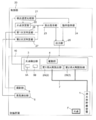
- FIG. 1 is a block diagram showing the fire extinguishing system according to this embodiment as a function realizing means.
- the fire extinguishing system according to the present embodiment includes a fire extinguishing agent storage container 1 filled with a fire extinguishing agent, a fire extinguishing agent releasing unit 2 releasing the extinguishing agent, a fire point detecting unit 3 detecting a fire point F, and a fire point detecting unit
- the drive unit 4 changes the discharge direction of the extinguishant release unit 2 along with the detection direction of 3, the photographing unit 5 that photographs the fire point F, and the odor detection unit 6 that extracts surrounding gas and detects combustion gas.
- the extinguishant storage container 1, the extinguishant release unit 2, the fire point detection unit 3, the drive unit 4, the photographing unit 5, and the odor detection unit 6 are installed in the protected area 10.
- the protected area 10 is one space partitioned by walls and doors, such as a living room in a living space and a lobby of a hotel.
- the extinguishant storage container 1 may be installed outside the protected compartment 10.
- the extinguishant storage container 1 and the extinguishant discharge unit 2 are connected by a extinguishant pipe 7.
- the fire point detection unit 3 includes a plurality of non-contact temperature sensors 3A and 3B.
- the noncontact temperature sensors 3A and 3B an infrared sensor that detects thermal infrared can be used.
- each of the non-contact temperature sensors 3A and 3B is a monocular element, and obtains an average temperature in the field of view.
- the detection direction of the fire point detection unit 3 is changed by the drive unit 4, and the discharge direction of the extinguishant discharge unit 2 is also changed by the operation of the drive unit 4.
- the detection direction of the fire point detection unit 3 is changed toward the fire point F, and the discharge direction of the extinguishant discharge unit 2 is also changed toward the fire point F.
- two extinguishant release units 2 are provided.
- the first extinguishant release portion 2A includes a first extinguishant release portion 2A and a second extinguishant release portion 2B, and the first extinguishant release portion 2A and the second extinguishant release portion 2B have different release directions. Therefore, the fire extinguishing agent can be released from different directions to the fire point F, and a limited fire extinguishing agent can be effectively used, and a reliable fire extinguishing can be performed.
- the fire extinguishing equipment is driven by the detection temperatures from the non-contact temperature sensors 3A and 3B, the flame information at the fire point F photographed by the photographing unit 5, and the combustion gas information detected by the odor detection unit 6
- the control unit 20 controls the drive of the unit 4 and the release of the extinguishant from the extinguishant release unit 2.
- the control unit 20 includes a detected temperature comparison unit 21, a fire point determination unit 22, a release instruction unit 23, an operation instruction unit 24, an output unit 25, a first fire determination unit 26, and a second fire determination unit 27. , And directs the extinguishant release unit 2 in the detection direction of the fire point F detected by the fire point detection unit 3, and performs control to release the extinguishant from the extinguishant release unit 2.
- the detected temperature comparing unit 21 compares the detected temperatures detected by the plurality of non-contact temperature sensors 3A and 3B.
- the fire point determination unit 22 determines a position at which the difference between the detected temperatures is minimum as the fire point F.
- the release instruction unit 23 causes the extinguishant release unit 2 to release the extinguishant.
- the operation instructing unit 24 operates the driving unit 4 in the direction in which the difference between the detected temperatures of the non-contact temperature sensors 3A and 3B decreases as a result of the comparison by the detected temperature comparing unit 21.
- the output unit 25 outputs the operation instruction from the operation instruction unit 24 to the drive unit 4, and when the fire point determination unit 22 determines the fire point F, the discharge instruction from the discharge instruction unit 23 is the extinguishant release unit Output to 2.
- the first fire determination unit 26 determines whether a fire is generated from a fire element including at least one of the shape, size, color, brightness, and fluctuation of the flame at the fire point F photographed by the photographing unit 5.
- the second fire determination unit 27 determines from the combustion gas detected by the odor detection unit 6 whether it is a fire or not.
- the fire extinguishing agent release unit 2 is Output release instructions.
- a release instruction is issued to the extinguishant release unit 2. Output.
- the release instruction to the extinguishant release unit 2 may be operated by operating the on-off valve provided in the extinguishant pipe 7. It is.
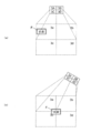
- FIG. 2 is explanatory drawing which shows the change of the detection direction of the non-contact temperature sensor in the fire extinguishing installation by a present Example.
- FIG. 2 shows a change in detection direction when two non-contact temperature sensors 3A and 3B are used, and FIG. 2 (a) shows a state before the change and FIG. 2 (b) shows a state after the change.
- FIG. 2 (a) when a fire point F exists in the detection area 3a of the non-contact temperature sensor 3A, the detection temperature of the detection area 3a of the non-contact temperature sensor 3A is the non-contact temperature sensor 3B. Higher than the detection area 3b of Therefore, the fire point detection unit 3 is operated in the direction of the non-contact temperature sensor 3A where the detected temperature is high.
- the difference of the detection temperature of the detection area 3a and the detection area 3b becomes the minimum in the position where the fire point F exists in the detection area 3a and the detection area 3b.
- the fire point detection unit 3 and the fire point detection unit 3 release the extinguishant by operating the detection direction of the fire point detection unit 3 at a position where the difference between the detection temperatures of the plurality of non-contact temperature sensors 3A and 3B is minimized. Since the unit 2 operates, the discharge direction of the extinguishant discharge unit 2 can be set to the fire point F, and the extinguishant can be released toward the fire point F.
- the position where the difference in detected temperature is minimum is not limited to the case where the detected temperatures are the same, and the difference in detected temperature may be determined as a predetermined threshold value or less, or the non-contact temperature with high detected temperature You may judge by the change which the detected temperature of sensor 3A turns to increase and decline.
- FIG. 3 is an explanatory view showing the change of the detection direction of the non-contact temperature sensor in the fire extinguishing equipment according to another embodiment.
- FIG. 3 shows a change in detection direction when four non-contact temperature sensors 3A, 3B, 3C, 3D are used
- FIG. 3 (a) shows a state before the change
- FIG. 3 (b) shows a state after the change.
- FIG. 3 (a) when a fire point F exists in the detection area 3a of the noncontact temperature sensor 3A, the detected temperature of the detection area 3a of the noncontact temperature sensor 3A is the other noncontact temperature. It is higher than the detection areas 3b, 3c, 3d of the sensors 3B, 3C, 3D.
- the fire point detection unit 3 is operated in the direction of the non-contact temperature sensor 3A where the detected temperature is high. And as shown in FIG.3 (b), in the position where the fire point F exists in the detection area 3a, the detection area 3b, the detection area 3c, and the detection area 3d, of each detection area 3a, 3b, 3c, 3d The difference in detected temperature is minimized.
- the detection point of the fire point detection unit 3 is operated at a position where the difference between the detection temperatures of the plurality of non-contact temperature sensors 3A, 3B, 3C, 3D is minimized, thereby the fire point detection unit 3
- the release direction of the extinguishant release unit 2 can be set to the fire point F, and the extinguishant can be released toward the fire point F. Therefore, the initial fire extinguishing can be reliably performed using the limited fire extinguishing agent filled in the fire extinguisher storage container 1.
- the position where the difference in detected temperature is minimum is not limited to the case where the detected temperatures are the same, and the difference in detected temperature may be determined as a predetermined threshold value or less, or the non-contact temperature with high detected temperature You may judge by the change which the detected temperature of sensor 3A turns to increase and decline.
- the fire point F exists in the detection area 3a of the non-contact temperature sensor 3A
- the fire point F is in any detection area 3a, 3b, 3c, 3d. Even when it does not exist, the detected temperatures of the detection areas 3a, 3b, 3c, 3d are different from each other, so the fire point detection unit 3 can be operated.
- FIG. 4 is a flowchart showing the operation of the fire extinguishing system according to the present embodiment.
- the fire point detection unit 3 acquires the detected temperature detected by each non-contact temperature sensor 3A, 3B.
- the detected temperature obtained in step 1 is compared by the detected temperature comparing unit 21 (step 2).
- the operation instructing unit 24 operates the fire point detecting unit 3 by a predetermined amount in the direction of the non-contact temperature sensor 3A where the detected temperature is high (step 3).
- the fire point detection unit 3 is operated in step 3, and after a predetermined amount of operation, the detected temperature detected by the non-contact temperature sensors 3A and 3B is acquired again in step 1, and the detected temperatures in step 2 are compared. If it is determined in step 2 that the difference between the detected temperatures is the smallest, the determined position is determined as the fire point F (step 4)
- step 4 When the fire point F is determined in step 4, the fire point F is photographed by the photographing unit 5 (step 5). From the flame element (including at least one of the shape, size, color, brightness, and fluctuation of the flame) at the fire point F photographed in step 5, the first fire determination unit 26 determines whether or not a fire occurs ( Step 6). When it is determined in step 6 that the first fire determination unit 26 does not indicate a fire, the process returns to step 1.
- step 6 when it is determined by the first fire determination unit 26 that there is a fire, the odor detection unit 6 detects the combustion gas (step 7). From the combustion gas detected in step 7, the second fire determination unit 27 determines whether or not there is a fire (step 8). If it is determined in step 8 that the second fire determination unit 27 determines that there is no fire, the process returns to step 1.
- step 8 If it is determined in step 8 that the second fire determination unit 27 determines that there is a fire, the output unit 25 outputs a release instruction to the extinguishant release unit 2 (step 9).
- the operation instructing unit 24 operates the fire point detection unit 3 by a predetermined amount in the direction of the non-contact temperature sensor 3A where the detected temperature is high, and the detection temperature comparison unit 21 detects again after the predetermined amount of operation.
- the initial fire extinguishing with respect to the fire point F can be reliably performed with a simple device. Therefore, the initial fire extinguishing can be reliably performed using the limited fire extinguishing agent filled in the fire extinguisher storage container 1.
- the operations in steps 1 to 4 may be performed to determine the fire point F and output the release instruction in step 9.
- the present invention is most suitable for a fire extinguishing system using a fire extinguishing agent filled in a fire extinguisher storage container, but is also applicable to a fire extinguishing system using fire extinguishing water such as a sprinkler.
Landscapes
- Health & Medical Sciences (AREA)
- Public Health (AREA)
- Business, Economics & Management (AREA)
- Emergency Management (AREA)
- Fire-Extinguishing By Fire Departments, And Fire-Extinguishing Equipment And Control Thereof (AREA)
- Fire Alarms (AREA)
Abstract
L'invention concerne un équipement d'extinction d'incendie qui permet de décharger un agent d'extinction d'incendie vers un point d'incendie malgré une grande section de protection, et de réaliser de manière fiable une extinction initiale d'incendie à l'aide d'une quantité limitée de l'agent d'extinction d'incendie. La présente invention comprend une unité d'entraînement (4), qui change la direction de détection d'une unité de détection de point d'incendie (3) et la direction de décharge d'une unité de décharge d'agent d'extinction d'incendie (2). L'unité de détection de point d'incendie (3) est constituée d'une pluralité de capteurs de température sans contact (3A, 3B). Une unité de commande (20) comprend : une unité de comparaison de températures détectées (21), qui compare la température détectée par chacun de la pluralité des capteurs de température sans contact (3A, 3B) ; une unité d'instruction d'actionnement (24) qui, sur la base du résultat de la comparaison obtenu par l'unité de comparaison de températures détectées (21), actionne l'unité d'entraînement (4) dans la direction dans laquelle la différence entre les températures détectées est relativement petite ; une unité de détermination de point d'incendie (22), qui détermine le point auquel la différence entre les températures détectées est la plus petite en tant que le point d'incendie (F) ; une unité d'instruction de décharge (23), qui amène l'unité de décharge d'agent d'extinction d'incendie à mettre en oeuvre une opération de décharge ; et une unité de sortie (25), qui produit une instruction de décharge à partir de l'unité d'instruction de décharge (23) lorsque le point d'incendie (F) est déterminé par l'unité de détermination de point d'incendie (22).
Applications Claiming Priority (2)
| Application Number | Priority Date | Filing Date | Title |
|---|---|---|---|
| JP2017134368A JP6900005B2 (ja) | 2017-07-10 | 2017-07-10 | 消火設備 |
| JP2017-134368 | 2017-07-10 |
Publications (1)
| Publication Number | Publication Date |
|---|---|
| WO2019013079A1 true WO2019013079A1 (fr) | 2019-01-17 |
Family
ID=65001260
Family Applications (1)
| Application Number | Title | Priority Date | Filing Date |
|---|---|---|---|
| PCT/JP2018/025446 Ceased WO2019013079A1 (fr) | 2017-07-10 | 2018-07-05 | Équipement d'extinction d'incendie |
Country Status (2)
| Country | Link |
|---|---|
| JP (1) | JP6900005B2 (fr) |
| WO (1) | WO2019013079A1 (fr) |
Cited By (1)
| Publication number | Priority date | Publication date | Assignee | Title |
|---|---|---|---|---|
| CN110174905A (zh) * | 2019-05-28 | 2019-08-27 | 华中科技大学 | 一种具有温差导航功能的无人机 |
Families Citing this family (2)
| Publication number | Priority date | Publication date | Assignee | Title |
|---|---|---|---|---|
| KR102635977B1 (ko) * | 2021-07-08 | 2024-02-14 | 주식회사 가스트론 | 다중 방호구역을 위한 자동 소화 시스템 및 이의 동작 방법 |
| JP7341363B1 (ja) | 2023-01-23 | 2023-09-08 | 千住スプリンクラー株式会社 | 消火システム |
Citations (7)
| Publication number | Priority date | Publication date | Assignee | Title |
|---|---|---|---|---|
| JPS57115266A (en) * | 1981-01-05 | 1982-07-17 | Nohmi Bosai Kogyo Co Ltd | Fire extinguishing device |
| JPS62281974A (ja) * | 1986-05-28 | 1987-12-07 | 日本精機株式会社 | 自動消火装置 |
| JPH0470382U (fr) * | 1990-10-29 | 1992-06-22 | ||
| JPH0933338A (ja) * | 1995-07-25 | 1997-02-07 | Itachibori Seisakusho:Kk | 火災検知方法 |
| JPH09147261A (ja) * | 1995-11-24 | 1997-06-06 | Matsushita Electric Ind Co Ltd | 火災検出装置 |
| JPH10126765A (ja) * | 1996-10-21 | 1998-05-15 | Hochiki Corp | 炎検出装置及び検出方法 |
| JP2000132761A (ja) * | 1998-10-28 | 2000-05-12 | Yazaki Corp | 警報器 |
Family Cites Families (2)
| Publication number | Priority date | Publication date | Assignee | Title |
|---|---|---|---|---|
| JPH0630893U (ja) * | 1992-09-16 | 1994-04-22 | 日本ドライケミカル株式会社 | 火災監視装置 |
| KR101628025B1 (ko) * | 2015-02-02 | 2016-06-08 | 장현실 | 워터셔터용 회전형 노즐을 조정하는 제어장치 |
-
2017
- 2017-07-10 JP JP2017134368A patent/JP6900005B2/ja active Active
-
2018
- 2018-07-05 WO PCT/JP2018/025446 patent/WO2019013079A1/fr not_active Ceased
Patent Citations (7)
| Publication number | Priority date | Publication date | Assignee | Title |
|---|---|---|---|---|
| JPS57115266A (en) * | 1981-01-05 | 1982-07-17 | Nohmi Bosai Kogyo Co Ltd | Fire extinguishing device |
| JPS62281974A (ja) * | 1986-05-28 | 1987-12-07 | 日本精機株式会社 | 自動消火装置 |
| JPH0470382U (fr) * | 1990-10-29 | 1992-06-22 | ||
| JPH0933338A (ja) * | 1995-07-25 | 1997-02-07 | Itachibori Seisakusho:Kk | 火災検知方法 |
| JPH09147261A (ja) * | 1995-11-24 | 1997-06-06 | Matsushita Electric Ind Co Ltd | 火災検出装置 |
| JPH10126765A (ja) * | 1996-10-21 | 1998-05-15 | Hochiki Corp | 炎検出装置及び検出方法 |
| JP2000132761A (ja) * | 1998-10-28 | 2000-05-12 | Yazaki Corp | 警報器 |
Cited By (1)
| Publication number | Priority date | Publication date | Assignee | Title |
|---|---|---|---|---|
| CN110174905A (zh) * | 2019-05-28 | 2019-08-27 | 华中科技大学 | 一种具有温差导航功能的无人机 |
Also Published As
| Publication number | Publication date |
|---|---|
| JP6900005B2 (ja) | 2021-07-07 |
| JP2019013617A (ja) | 2019-01-31 |
Similar Documents
| Publication | Publication Date | Title |
|---|---|---|
| US20130242091A1 (en) | Method for sensing fire and transferring fire information | |
| US20160354626A1 (en) | Automatic fire targeting and extinguishing apparatus and method | |
| KR101990977B1 (ko) | 소화 시스템 | |
| WO2019013079A1 (fr) | Équipement d'extinction d'incendie | |
| US20190054333A1 (en) | Autonomous fire locating and suppression apparatus and method | |
| KR101296403B1 (ko) | 스마트 기기를 이용한 무인 자동 소화기 제어 시스템 및 방법 | |
| KR20220159883A (ko) | IoT 기능이 결합된 소화기 및 그 제어방법 | |
| KR102530287B1 (ko) | 공동주택의 소방 예방 시스템 | |
| JP2009296331A (ja) | セキュリティシステム | |
| JP2019179573A (ja) | 火災検知システム及び火災検知方法 | |
| KR102866489B1 (ko) | 화재 감지 및 진압 시스템 및 그 방법 | |
| JP6883801B2 (ja) | 消火設備 | |
| JP2010046316A (ja) | 消火システム | |
| KR101663989B1 (ko) | 지능형 소방 시스템 | |
| JP2015158814A (ja) | 火災検知システム及び火災検知方法 | |
| JPH0346776Y2 (fr) | ||
| US12311562B2 (en) | Firefighter robotic system | |
| JP6546314B2 (ja) | 火災検知システム及び火災検知方法 | |
| KR102111212B1 (ko) | 가스를 검출하는 센서를 이용한 화재감지장치 및 방법, 시스템 | |
| KR20060025778A (ko) | 자동 소화 시스템 | |
| JP2006305173A (ja) | 防災装置 | |
| RU2745641C1 (ru) | Роботизированная установка пожаротушения с системой коррекции струи | |
| JP7316914B2 (ja) | 消火システム | |
| KR102813888B1 (ko) | 선박의 화재 진압 시스템 및 방법 | |
| KR102627402B1 (ko) | 주변기기 연동이 가능한 IoT 스마트 스프링클러 |
Legal Events
| Date | Code | Title | Description |
|---|---|---|---|
| 121 | Ep: the epo has been informed by wipo that ep was designated in this application |
Ref document number: 18832481 Country of ref document: EP Kind code of ref document: A1 |
|
| NENP | Non-entry into the national phase |
Ref country code: DE |
|
| 122 | Ep: pct application non-entry in european phase |
Ref document number: 18832481 Country of ref document: EP Kind code of ref document: A1 |