WO2019013216A1 - Dispositif d'éclairage à del à fonction de haut-parleur, et procédé d'extraction de lumière et de son d'un dispositif d'éclairage à del à fonction de haut-parleur - Google Patents
Dispositif d'éclairage à del à fonction de haut-parleur, et procédé d'extraction de lumière et de son d'un dispositif d'éclairage à del à fonction de haut-parleur Download PDFInfo
- Publication number
- WO2019013216A1 WO2019013216A1 PCT/JP2018/026073 JP2018026073W WO2019013216A1 WO 2019013216 A1 WO2019013216 A1 WO 2019013216A1 JP 2018026073 W JP2018026073 W JP 2018026073W WO 2019013216 A1 WO2019013216 A1 WO 2019013216A1
- Authority
- WO
- WIPO (PCT)
- Prior art keywords
- light
- sound
- extraction
- lighting device
- reflection plate
- Prior art date
- Legal status (The legal status is an assumption and is not a legal conclusion. Google has not performed a legal analysis and makes no representation as to the accuracy of the status listed.)
- Ceased
Links
Images






Classifications
-
- F—MECHANICAL ENGINEERING; LIGHTING; HEATING; WEAPONS; BLASTING
- F21—LIGHTING
- F21V—FUNCTIONAL FEATURES OR DETAILS OF LIGHTING DEVICES OR SYSTEMS THEREOF; STRUCTURAL COMBINATIONS OF LIGHTING DEVICES WITH OTHER ARTICLES, NOT OTHERWISE PROVIDED FOR
- F21V33/00—Structural combinations of lighting devices with other articles, not otherwise provided for
- F21V33/0004—Personal or domestic articles
- F21V33/0052—Audio or video equipment, e.g. televisions, telephones, cameras or computers; Remote control devices therefor
- F21V33/0056—Audio equipment, e.g. music instruments, radios or speakers
-
- G—PHYSICS
- G10—MUSICAL INSTRUMENTS; ACOUSTICS
- G10K—SOUND-PRODUCING DEVICES; METHODS OR DEVICES FOR PROTECTING AGAINST, OR FOR DAMPING, NOISE OR OTHER ACOUSTIC WAVES IN GENERAL; ACOUSTICS NOT OTHERWISE PROVIDED FOR
- G10K11/00—Methods or devices for transmitting, conducting or directing sound in general; Methods or devices for protecting against, or for damping, noise or other acoustic waves in general
- G10K11/18—Methods or devices for transmitting, conducting or directing sound
- G10K11/22—Methods or devices for transmitting, conducting or directing sound for conducting sound through hollow pipes, e.g. speaking tubes
-
- G—PHYSICS
- G10—MUSICAL INSTRUMENTS; ACOUSTICS
- G10K—SOUND-PRODUCING DEVICES; METHODS OR DEVICES FOR PROTECTING AGAINST, OR FOR DAMPING, NOISE OR OTHER ACOUSTIC WAVES IN GENERAL; ACOUSTICS NOT OTHERWISE PROVIDED FOR
- G10K9/00—Devices in which sound is produced by vibrating a diaphragm or analogous element, e.g. fog horns, vehicle hooters or buzzers
- G10K9/12—Devices in which sound is produced by vibrating a diaphragm or analogous element, e.g. fog horns, vehicle hooters or buzzers electrically operated
- G10K9/122—Devices in which sound is produced by vibrating a diaphragm or analogous element, e.g. fog horns, vehicle hooters or buzzers electrically operated using piezoelectric driving means
-
- H—ELECTRICITY
- H04—ELECTRIC COMMUNICATION TECHNIQUE
- H04R—LOUDSPEAKERS, MICROPHONES, GRAMOPHONE PICK-UPS OR LIKE ACOUSTIC ELECTROMECHANICAL TRANSDUCERS; ELECTRIC HEARING AIDS; PUBLIC ADDRESS SYSTEMS
- H04R1/00—Details of transducers, loudspeakers or microphones
- H04R1/02—Casings; Cabinets ; Supports therefor; Mountings therein
- H04R1/025—Arrangements for fixing loudspeaker transducers, e.g. in a box, furniture
-
- H—ELECTRICITY
- H04—ELECTRIC COMMUNICATION TECHNIQUE
- H04R—LOUDSPEAKERS, MICROPHONES, GRAMOPHONE PICK-UPS OR LIKE ACOUSTIC ELECTROMECHANICAL TRANSDUCERS; ELECTRIC HEARING AIDS; PUBLIC ADDRESS SYSTEMS
- H04R1/00—Details of transducers, loudspeakers or microphones
- H04R1/02—Casings; Cabinets ; Supports therefor; Mountings therein
- H04R1/028—Casings; Cabinets ; Supports therefor; Mountings therein associated with devices performing functions other than acoustics, e.g. electric candles
-
- F—MECHANICAL ENGINEERING; LIGHTING; HEATING; WEAPONS; BLASTING
- F21—LIGHTING
- F21Y—INDEXING SCHEME ASSOCIATED WITH SUBCLASSES F21K, F21L, F21S and F21V, RELATING TO THE FORM OR THE KIND OF THE LIGHT SOURCES OR OF THE COLOUR OF THE LIGHT EMITTED
- F21Y2115/00—Light-generating elements of semiconductor light sources
- F21Y2115/10—Light-emitting diodes [LED]
-
- H—ELECTRICITY
- H04—ELECTRIC COMMUNICATION TECHNIQUE
- H04R—LOUDSPEAKERS, MICROPHONES, GRAMOPHONE PICK-UPS OR LIKE ACOUSTIC ELECTROMECHANICAL TRANSDUCERS; ELECTRIC HEARING AIDS; PUBLIC ADDRESS SYSTEMS
- H04R1/00—Details of transducers, loudspeakers or microphones
- H04R1/20—Arrangements for obtaining desired frequency or directional characteristics
- H04R1/32—Arrangements for obtaining desired frequency or directional characteristics for obtaining desired directional characteristic only
- H04R1/34—Arrangements for obtaining desired frequency or directional characteristics for obtaining desired directional characteristic only by using a single transducer with sound reflecting, diffracting, directing or guiding means
- H04R1/36—Arrangements for obtaining desired frequency or directional characteristics for obtaining desired directional characteristic only by using a single transducer with sound reflecting, diffracting, directing or guiding means by using a single aperture of dimensions not greater than the shortest operating wavelength
-
- H—ELECTRICITY
- H04—ELECTRIC COMMUNICATION TECHNIQUE
- H04R—LOUDSPEAKERS, MICROPHONES, GRAMOPHONE PICK-UPS OR LIKE ACOUSTIC ELECTROMECHANICAL TRANSDUCERS; ELECTRIC HEARING AIDS; PUBLIC ADDRESS SYSTEMS
- H04R17/00—Piezoelectric transducers; Electrostrictive transducers
-
- H—ELECTRICITY
- H04—ELECTRIC COMMUNICATION TECHNIQUE
- H04R—LOUDSPEAKERS, MICROPHONES, GRAMOPHONE PICK-UPS OR LIKE ACOUSTIC ELECTROMECHANICAL TRANSDUCERS; ELECTRIC HEARING AIDS; PUBLIC ADDRESS SYSTEMS
- H04R2307/00—Details of diaphragms or cones for electromechanical transducers, their suspension or their manufacture covered by H04R7/00 or H04R31/003, not provided for in any of its subgroups
- H04R2307/025—Diaphragms comprising polymeric materials
-
- H—ELECTRICITY
- H04—ELECTRIC COMMUNICATION TECHNIQUE
- H04R—LOUDSPEAKERS, MICROPHONES, GRAMOPHONE PICK-UPS OR LIKE ACOUSTIC ELECTROMECHANICAL TRANSDUCERS; ELECTRIC HEARING AIDS; PUBLIC ADDRESS SYSTEMS
- H04R7/00—Diaphragms for electromechanical transducers; Cones
- H04R7/02—Diaphragms for electromechanical transducers; Cones characterised by the construction
- H04R7/04—Plane diaphragms
-
- H—ELECTRICITY
- H04—ELECTRIC COMMUNICATION TECHNIQUE
- H04R—LOUDSPEAKERS, MICROPHONES, GRAMOPHONE PICK-UPS OR LIKE ACOUSTIC ELECTROMECHANICAL TRANSDUCERS; ELECTRIC HEARING AIDS; PUBLIC ADDRESS SYSTEMS
- H04R9/00—Transducers of moving-coil, moving-strip, or moving-wire type
- H04R9/06—Loudspeakers
Definitions
- the present invention relates to an LED lighting device with a speaker function with excellent design and good sound quality, and a method for extracting light and sound from the LED lighting device with a speaker function.
- a lighting device has been developed that combines the function of a speaker and the function of lighting that emits light, which can simultaneously generate both light and sound.
- an LED light source is disposed on a support of a voice coil, and a speaker device that blinks the LED light source by outputting induced current induced by vibration of the voice coil to an induction coil by a magnetic field generated by vibration of the voice coil.
- Patent Document 1 proposes a speaker device that blinks the LED light source by outputting induced current induced by vibration of the voice coil to an induction coil by a magnetic field generated by vibration of the voice coil.
- Patent Document 1 uses an LED light source as an indicator function that enjoys blinking of an LED light source that blinks along with a change in sound pressure of vibration. According to the speaker of Patent Document 1, it is possible to make the LED light source blink in response to the level of the reproduced sound to satisfy the sense of taste of the audience.
- a light source unit a circuit board on which a predetermined circuit is mounted, a base used for supplying power to the light source unit and the circuit, a translucent cover covering the light source unit, an outer shell surrounding the circuit board, a light source
- a bulb-type light source device having a heat dissipating metal casing portion thermally connected to a unit.
- the light bulb type light source device of Patent Document 2 includes a speaker drive substrate on which a speaker drive circuit for driving a speaker is mounted, and an outer portion to a speaker drive substrate for thermal connection with a predetermined circuit. The protrusion protrudes toward the end.
- the frame for LED lighting apparatuses consists of an inner side frame and an outer side frame.
- a frame for an LED lighting device or the like configured of a sheet made of a microfoamed resin has been proposed (Patent Document 3).
- Patent Document 3 has a double-structured frame in which an inner frame is disposed inside the outer frame.
- the surface side of the inner frame functions as a reflector. Therefore, a light guiding space which is a first light guiding space is formed between the surface side of the inner frame and the opening.
- the back side of the inner frame and the front side of the outer frame function as a reflector. Therefore, a light guide space which is a second light guide space is formed between the back surface side of the inner frame and the front surface side of the outer frame.
- a light source having a plurality of LED chips having different emission wavelengths a face sheet formed of a diffuse reflection sheet having a large number of openings for light extraction, and a face on the side opposite to the light emission surface side of the face sheet
- an LED lighting apparatus including a rear sheet made of a diffuse reflection sheet that diffusely reflects light diffused and reflected by a sheet to the face sheet side (Patent Document 4).
- the medium between the face sheet and the rear sheet is air, and each face sheet has openings so that direct light from the light source is not emitted to the outside and the luminance on the light emitting surface side becomes uniform. Is formed.
- the opening size is smaller as the opening is closer to the light source, and the aspect ratio of each opening is set so that direct light from the light source is not emitted to the outside.
- the face sheet is thicker as it is closer to the optical axis of the light source, and the aspect ratio of each opening is set so that direct light from the light source is not emitted to the outside. According to Patent Document 4, it is possible to obtain an LED lighting device that can improve the light extraction efficiency and can suppress the occurrence of color unevenness.
- Patent Document 5 A light source and a sound source supply device have been proposed (Patent Document 5).
- the sleeping directional light source and sound source supply device in Patent Document 5 includes a superdirective speaker for emitting voice or music, a directional LED illumination light for illuminating, and a speaker for controlling voice or music of the superdirective speaker.
- the storage unit includes a pattern control unit that provides the sleeper with a pattern selected in advance from the patterns stored in the storage unit when the sleeper goes to bed, goes to bed, or wakes up.
- Patent Document 6 a driving support device and a driving support method have been proposed that can issue a warning of contents according to the driving situation when the vehicle deviates from the lane.
- Patent Document 6 determines the warning level by calculating the lane deviation amount with respect to the traveling lane of the own vehicle, and determining whether the own vehicle tends to return to the relevant traveling lane, thereby determining the warning level. And a control unit for giving a warning of the contents. At this time, a light pattern corresponding to the warning level is displayed on the display device, a warning of lane departure of the vehicle is controlled by the voice output of the in-car speaker, and a lane departure warning of the vehicle is generated at a volume according to the warning level. It can be carried out.
- the design of the lighting device is impaired because the speaker is disposed in front of the lighting device. Further, in order to secure the light extraction area of the lighting device, the size of the speaker can not be increased. Therefore, it is necessary to apply a small speaker with poor sound quality. Moreover, in order to arrange a speaker of a certain size, it is necessary to enlarge a lighting device.
- the LED illumination device of Patent Document 1 is not provided with a light extraction member, and thus can not diffuse light. Therefore, the direct light from the light source is emitted, and the glare feeling is enhanced. In addition, in the first place, in front of the speaker, light is emitted as an indicator in conjunction with the sound pressure level of the speaker, and the illumination is insufficient for illumination.
- Patent Document 2 is different in structure from the present invention because the diaphragm is exposed in the sound extraction direction. As mentioned above, the size of the speakers is limited and the sound quality needs to be sacrificed. In addition, applying a large speaker increases the size of the device.
- Patent Document 3 a light extraction member is provided in the light extraction portion, and a frame made of a light reflection plate is provided at a position facing the light extraction member, but the vibration of the speaker is absorbed and reflected by the light transmission member. And sound pressure levels are low.
- Patent Document 4 a large number of slit-like openings or holes are provided in the light extraction portion, and the opening portion is adjusted to adjust the luminance on the extraction surface of the light extracted from the light extraction portion to be uniform. Although it is for adjusting the cross-sectional area and the aspect ratio of the opening, since no light extraction member is provided, the glare feeling is enhanced.
- the lighting apparatus of Patent Document 5 selects a pattern previously selected from the patterns stored in the storage unit when the sleeping person goes to bed, going to bed, or when getting up, and is a direct-directed light that is a directional lighting apparatus. It controls the lighting, and it is not possible to output warning voices or instruction voices from the driving support system based on the received signals, instead of selecting signals.
- patent document 6 is what receives a predetermined signal and outputs a warning sound, it is not the illuminating device with which the speaker was incorporated.
- the present invention has been made in view of such problems, and it is an object of the present invention to provide a small-sized LED illumination apparatus with a speaker function with good sound quality and a method of extracting light and sound from the LED illumination apparatus with a speaker function. Do.
- the first invention combines an outer light reflecting plate which also serves as a hollow outer frame having an opening and an inner frame which is disposed at a position facing the outer light reflecting plate.
- An inner light reflector, a frame member attached to the opening, an LED light source disposed in a space formed between opposing surfaces of the inner light reflector and the outer light reflector, and the LED of the space A light source disposed at a position different from the light source or at an outer surface of the space of the outer light reflection plate, wherein the frame member is formed with a light extraction portion, and the outer light reflection plate and the light source
- the opening of the inner light reflecting plate is fixed to the frame member, and the frame member is provided with a separate extraction portion capable of extracting sound and light from the inside to the outside of the lighting device separately from the light extraction portion.
- the separate outlet has a predetermined length
- the light extraction space is formed inside the lighting device, wherein the sound generated by the vibration of the sound source is directly taken out from the other extraction portion to the outside of the
- the LED light source and the sound source may be disposed at different positions on either or both of the inner light reflector and the outer light reflector. In the case of being disposed on both the inner light reflecting plate and the outer light reflecting plate, they may not be disposed to face each other, but may be disposed to face each other. Moreover, although it is desirable to use a piezoelectric element as a sound source used for this illuminating device, a small dynamic speaker can also be used.
- the LED light source and the joint portion of the sound source to which the sound source directly applies vibration are disposed so as to face each other at the approximate center of the space, or at the inner surface of the approximate center of the outer light reflection plate.
- An LED light source is disposed, and the sound source is disposed on the outer surface substantially at the center of the outer light reflection plate, and the frame member is constituted by an inner frame portion, an outer frame portion, and a light extraction portion
- the light extraction portion is formed between the inner frame portion and the outer frame portion so as to be adjacent to either the inner frame portion or the outer frame portion, and the opening portion of the outer light reflection plate is
- the frame is fixed to the outer frame portion of the frame member, the opening of the inner light reflecting plate is fixed to the inner frame portion, and either the outer frame portion or the inner frame portion has the other extraction portion. It may be done.
- the LED light source substantially at the center of the light guide space formed by the inner light reflection plate and the outer light reflection plate, light in which mutual diffuse reflection is repeated many times is taken out as uniform indirect light from the LED lighting device. It is possible.
- the LED light source and the joint portion of the sound source to which the sound source directly applies vibration are disposed so as to face each other at the approximate center of the space, or at the inner surface of the approximate center of the outer light reflection plate.
- An LED light source is disposed, and the sound source is disposed on an outer surface substantially at the center of the outer light reflection plate, and the frame member includes an inner frame portion and a light extraction portion, and the light extraction is performed.
- the portion is formed on the outer side of the inner frame portion adjacent to the inner frame portion, the opening of the outer light reflection plate is fixed to the light extraction portion of the frame member, and the opening of the inner light reflection plate
- a part may be fixed to the inner frame part, and the inner frame part may have the other taking out part.
- the LED light source substantially at the center of the light guiding space formed by the inner light reflection plate and the outer light reflection plate, the light in which the inter-diffuse reflection is repeated many times is taken out as uniform indirect light from the LED lighting device. Is possible.
- the other extraction unit is an outer frame portion for the sound and light intakes of the sound source and the inner space side where the LED light source is disposed, and the sound and light extraction openings opened to the outside of the lighting device.
- any one of the inner frame portion, or outside the inner frame portion adjacent to the inner frame portion, the sound and light inlet and the sound and light outlet are mutually separated by a predetermined distance It may be formed to be separated and connected continuously.
- the light source is disposed substantially at the center of any one of the outside light reflecting plate or the inside light reflecting plate, and the LED light source is disposed at substantially the center of the reflecting plate where the sound source is not disposed.
- a plurality may be provided.
- the inner light reflection plate may be disposed on the bottom surface of the inner frame so as to face the outer light reflection plate directly or through a wiring board.
- the other extraction portion is formed in the inner frame portion, an inner storage portion is formed inside the other extraction portion, and an inner illumination space in which a light reflection plate is provided on the inner surface of the inner storage portion is formed.
- the inner LED light source may be provided at any position of the inner illumination space, and a light extraction member may be disposed at the light extraction portion from the inner illumination space.
- the other takeout portion is formed in the inner frame portion, an inner storage portion is formed inside the another takeout portion, a plurality of storage portions are formed in the inner storage portion, and the storage portion in the central portion
- An inner LED light source may be disposed on the side, and one or more switches may be disposed on the outer side storage unit.
- the further extraction section has a light guiding space forming a bent waveguide arranged at an angle at which the sound and light inlets are not visible from the sound and light outlets, and the further extraction section comprises:
- the light guided from the inside may not be emitted directly from the sound and light outlet to the outside.
- the width of the sound and light extraction space connecting the sound and light intake of the other extraction part, the sound and light extraction port, the sound and light intake and the sound and light extraction port is In any case, it is extracted from the sound extraction port by setting it to 2 to 10 mm which is larger than the wavelength of the light of the LED light source and smaller than the wavelength of the sound wave of human audible range smaller than the wavelength of the sound extracted from the sound source. It may be possible to prevent the sounds from interfering with one another inside the sound extraction space.
- the inner surface of the sound and light extraction space of the another extraction portion may be made of a light reflective member.
- the inner surface of the sound and light extraction space of the another extraction portion may be made of a light absorbing member, or an antireflective film may be formed on the inner surface of the light extraction space.
- a resin such as a general-purpose resin such as PE or PP, an ABS resin, or a PC resin colored in black or gray with black pigment on the inner surface.
- the luminance of the light extracted from the light extraction part is higher than the luminance of the light extracted from the other extraction part, and the sound extracted from the other extraction part is larger than the sound extracted from the light extraction part .
- the luminance of light extracted from another light extraction portion is 10% or less of the luminance of light extracted from the light extraction portion or 5 It can also be less than%.
- the outer light reflection plate is a light reflection plate made of microfoam resin that doubles as an acoustic diaphragm, and the outer light reflection plate is a light to the aluminum oxide light reflection plate when the aluminum oxide light reflection plate is a standard plate.
- the reflectance ratio may be any of PET resin, PC resin, acrylic resin, or flame-retardant acrylic resin in which the total reflectance is 90% or more and the diffuse reflectance is 90% or more.
- the light extraction portion has a ring shape, a C shape, a D shape, an E shape, an F shape, an L shape, an H shape, a U shape, a ⁇ shape around the inner frame portion in plan view. It may be formed into a letter shape of any of the shape of " ⁇ ", or two ring shapes, D shape, C shape, I shape, etc. may be formed to face each other. .
- the ring shape includes shapes such as a circle, an ellipse, and an oval.
- the lighting device further includes a wiring or a receiver, and when a signal from an external signal transmission device is received by the wiring or the receiver, it is possible to output an audio corresponding to the signal from the piezoelectric element or the speaker.
- the lighting device may be an LED lighting device with a speaker function having a small dynamic type speaker substantially at the center of the outside light reflecting plate as a sound source.
- a small dynamic speaker instead of the piezoelectric element can improve the sound quality of the speaker.
- the sound source formed inside the illumination device is formed because the sound and light extraction space where the sound and light can be extracted from the inside to the outside of the illumination device is formed in another extraction portion.
- the sound generated by the vibration of can be taken out of the separate take-off directly to the outside of the lighting device. For this reason, it is possible to suppress sound from staying inside the lighting device.
- the frame member is composed of an inner frame portion, an outer frame portion, and a light extraction portion
- the light extraction portion is formed between the inner frame portion and the outer frame portion
- another extraction portion is It may be formed on either the outer frame portion or the inner frame portion.
- the frame member is composed of an inner frame portion and a light extraction portion
- the light extraction portion is formed on the outer side of the inner frame portion, and another extraction portion is formed in the inner frame portion. Just do it.
- the sound source is disposed inside or behind the lighting device, the sound source is not exposed on the outer surface of the lighting device. For this reason, the vibration area by a sound source can be made wide, ensuring the area of the light extraction part of an illuminating device. For this reason, it is possible to obtain a small-sized LED lighting device with a speaker function with good sound quality.
- another extraction section has an intake of sound and light on the inner space side where the sound source is disposed and an extraction port of sound and light opened to the outside of the lighting device at both ends, the sound and the light
- this space can be used as a sound and light extraction space which combines the sound extraction space and the light extraction space.
- the inner light reflection plate is disposed on the bottom surface of the inner frame so as to face the outer light reflection plate, so that the light is efficiently reflected by the outer light reflection plate and the inner light reflection plate, and light is extracted. It can guide light to the part.
- the sound source is disposed substantially at the center of either the outer light reflection plate or the inner light reflection plate, and one or more LED light sources are provided substantially at the center of the reflection plate where the sound source is not disposed.
- the reflection area of the outer light reflection plate or the inner light reflection plate can be efficiently secured.
- a plurality of LED light sources can be provided in a predetermined arrangement in consideration of the size and shape of the lighting device. In the case where a plurality of LED light sources are provided, it is desirable that the arrangement of the LED light sources be arranged at the center with respect to the center if not approximately the center. With such an arrangement, uniform light can be extracted from the light extraction portion.
- an inner storage space is formed further inside another takeout area, an inner LED light source is provided inside the inner storage space, and a light reflection plate is provided on the inner surface of the inner storage space to form an inner illumination space. Can. For this reason, light can be efficiently extracted separately from both the inner illumination space and the light extraction part.
- a plurality of storage sections are formed in the inner storage section, the inner LED light source is disposed in the central storage section, and the switch is disposed in the outer storage section, so that both the inner illumination space and the light extraction section Thus, the light can be efficiently extracted separately, and a switch for operating the lighting device can be disposed on the front of the lighting device.
- the separate outcoupling has a space forming a bent waveguide arranged at an angle where the sound and light intakes are not visible from the sound and light outcouplings, so that the further outcouplings are of the luminaire. It is possible to prevent the light guided from the internal sound and light inlet from being emitted directly from the sound and light outlet to the outside.
- the cross-sectional shape of the space forming the curved waveguide can be, for example, any of L-shaped, U-shaped, V-shaped and S-shaped.
- the width of the space connecting the sound and light inlet, the sound and light outlet, the sound and light inlet and the sound and light outlet is larger than the wavelength of the light from the LED light source, and is taken from the sound source It is possible to set to 2 to 10 mm below the wavelength of sound waves in the human audible range which is smaller than the wavelength of the sound to be generated. Since the aperture width is shorter than the wavelength of the sound, this can suppress interference and reflection as waves. It is also possible to prevent the sound and the light extracted from the light outlet from interfering with each other inside the sound and light extraction space.
- illumination can be obtained. It is possible to control the brightness of light taken out of the device. Set the ratio of the width of the sound and light inlet to the sound and light outlet wide, or increase the number of bends in the space connecting the sound and light inlet and the sound and light outlet in series. By doing this, the brightness of light taken out from the sound and light extraction port can be lowered.
- the inner surface of the sound and light extraction space with a light reflective member, it is possible to adjust the luminance of the light emitted from the sound and light extraction space.
- the brightness of light emitted from the light extraction space is adjusted by configuring the inner surface of the sound and light extraction space with a light absorbing member or forming an anti-reflection film on the inner surface of the light extraction space can do.
- the brightness of the light extracted from the light extraction portion is higher than the luminance of light extracted from the other extraction portion, and the sound extracted from the other extraction portion is larger than the sound extracted from the light extraction portion. It is possible to obtain a lighting device excellent in the quality and the decorativeness.
- a piezoelectric element or a speaker can be selected as a sound source.
- the dynamic speaker has a characteristic that the distortion in the low range is small and the large input is strong, so that the sound quality is superior to that of the piezoelectric speaker.
- the sound source is a damper or a dynamic speaker with an edge
- the sound quality can be improved as compared with the case of the piezoelectric element by further forming the diaphragm of the sound source with a micro-foam resin.
- the diffuse reflectance of light of the outer light reflector is 90% or more, it is possible to take out uniform light, and at the same time the diffuse reflectance is high, the speaker is used because the speaker is used. Flickering of light can be suppressed even when it is vibrated.
- the light reflection plate which also serves as the acoustic diaphragm vibrates.
- the light reflection plate which also serves as the acoustic diaphragm vibrates.
- temporal and spatial fluctuations of the luminance distribution on the surface of the reflecting plate due to fine vibrations of the light reflecting plate occur. Flickering of light may occur due to changes in the reflection direction or the reflection intensity of light.
- the light reflection plate is made of micro-foamed resin, it has extremely high diffuse reflectance. That is, the distribution of the reflection direction with respect to the incident direction of light becomes gentler compared to the conventional metal plate or the like. For this reason, even if the light reflection plate vibrates, it is difficult to cause a change in the light reflection direction or the reflection intensity due to the temporal and spatial fluctuation of the luminance distribution on the surface of the reflection plate. As a result, the flicker of the reflected light at the time of vibration can be reduced. As described above, since flickering of illumination due to vibration can be prevented, the light reflection plate can be used as a diaphragm, and a compact and lightweight LED illumination device with a speaker function can be obtained.
- the light extraction portion has a ring shape, a C shape, a D shape, an E shape, an F shape, an L shape, an H shape, a U shape, a ⁇ shape around the inner frame portion in plan view If it is formed into a letter shape of any of a ⁇ shape, or a shape in which two ring shapes, a D shape, a C shape, or an I shape are mutually opposed, The design is excellent, and light can be extracted uniformly from the outer periphery of the lighting device.
- the lighting device has a receiver
- the signal corresponding to the signal can be output from the piezoelectric element or the speaker when the signal from the external signal transmission device is received by the receiver, for example, BlueTooth (for example, By transmitting and receiving an audio signal or a music signal by wireless such as a registered trademark, it is not necessary to connect the information device and the lighting device by wire.
- BlueTooth for example, By transmitting and receiving an audio signal or a music signal by wireless such as a registered trademark, it is not necessary to connect the information device and the lighting device by wire.
- the lighting device is connected to the external signal transmission device by wiring, it is possible to output the sound corresponding to the received signal from the piezoelectric element or the speaker when the signal from the external signal transmission device is received. .
- the dimensions of the opening of the sound and light inlet and the sound and light outlet are set to a predetermined width, the sound taken out from the light and the light outlet of the lighting device has almost no reflection or interference. You will get a clear sound because you won't receive it.
- a second invention is a method of extracting sound and light using the LED illumination apparatus with a speaker function according to the first invention, wherein the inner light reflection plate is disposed to face the outer light reflection plate. It is possible to form a light guiding space, and to extract the light mutually reflected by the inner light reflection plate and the outer light reflection plate as indirect light from the light extraction portion, and the illumination device is provided with the inner side.
- Another take-out part formed in either the frame part or the outer frame part is an intake of sound and light on the inner space side where the sound source is disposed, and a sound and light opening toward the outside of the lighting device.
- the sound and light inlet and the sound and light outlet are spaced apart from each other by a predetermined distance, and the sound and light inlet and the sound and light outlet are disposed.
- Sound and light that connect the two in a row An out-coupling space is formed, the further outcoupling being a light guiding space forming a curved waveguide arranged at an angle at which the sound and light intakes are not visible from the sound and light outcouplings,
- the sound generated by the vibration of the sound source from the other extraction portion is extracted directly from the sound and light extraction space to the outside, and the indirect light obtained by diffusely reflecting the light from the light source of the illumination device by the bent waveguide is It is a method for extracting light and sound from an LED lighting apparatus with a speaker function characterized by extracting from the bent waveguide of another extracting part.
- a third invention is a method of extracting sound and light using the LED illumination device with a speaker function according to the first invention, wherein the inner light reflection plate is disposed to face the outer light reflection plate. It is possible to form a light guiding space, and to extract the light mutually reflected by the inner light reflection plate and the outer light reflection plate as indirect light from the light extraction portion, and the illumination device is provided with the inner side.
- Another extraction part formed in the frame part has an intake of sound and light on the inner space side where the sound source is disposed, and an extraction port of sound and light opened to the outside of the lighting device.
- the sound and light inlet and the sound and light outlet are spaced apart from each other by a predetermined distance, and the sound and light inlet and the sound and light outlet are connected to each other in series.
- the other extraction portion is a light guiding space forming a curved waveguide disposed at an angle at which the sound and light inlets can not be visually recognized from the sound and light outlets, and the sound source from the other outlet
- the sound generated by the vibration of the light is extracted directly from the sound and light extraction space to the outside, and the indirect light obtained by diffusely reflecting the light from the light source of the illumination device by the bent waveguide is guided by the bent of the other extraction part.
- the light extraction portion and the outer light reflection plate can be directly fixed by not providing the outer frame outside the light extraction portion, the light extraction portion can be enlarged, and the light extraction portion can be extracted from the illumination device. It is possible to extract the light at a wide angle by expanding the illumination area of the light.
- direct light or indirect light can be extracted from the central portion of the lighting device and indirect light can be extracted from the outer peripheral portion of the lighting device.
- the sound taken out of the unit can be taken out directly from the inside of the lighting device to the outside.
- the inner surface of the sound and light extraction space may be formed with a light reflective member, it is possible to adjust the luminance of the light emitted from the light extraction space.
- the inner surface of the sound extraction space and the light extraction space may be formed of a light absorbing member, or an antireflective film may be formed on the inner surface of the sound and light extraction space to emit light from the sound and light extraction space. You can adjust the brightness of the
- the present invention it is possible to provide a small-sized LED illumination apparatus with a speaker function with good sound quality and a method for extracting light and sound from the LED illumination apparatus with a speaker function.
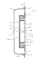
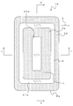
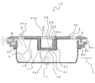
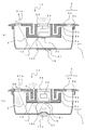
- FIG. 2 is a plan view showing the LED lighting device 1; AA line sectional drawing of FIG. BB sectional drawing of FIG. The top view which shows the LED lighting apparatus 1g.
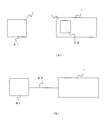
- FIG. 8 is a cross-sectional view taken along line II of FIG. 7; (A) shows a configuration in which the LED lighting device 1 and the external signal transmission device 41 are connected by wireless, and (b) shows a configuration in which the LED lighting device 1 and the external signal transmission device 41 are connected by the wiring 43 Figure showing. Sectional drawing which shows the LED lighting apparatus 1a.
- Sectional drawing which shows the LED lighting apparatus 1b is sectional drawing which shows the LED lighting apparatus 1c, (b) is sectional drawing which shows LED lighting apparatus 1d. (A) is sectional drawing which shows the LED lighting apparatus 1e, (b) is sectional drawing which shows the LED lighting apparatus 1f.
- FIG. 1 is a plan view of the LED lighting device 1
- FIG. 2 is a sectional view taken along the line AA of FIG. 1
- FIG. 3 is a sectional view taken along the line BB of FIG.
- the LED lighting device 1 mainly includes a frame member 3, an outer light reflection plate 11, an LED light source 15, a sound source 17, and the like.
- the LED lighting device 1 is an LED lighting device with a speaker function.
- the outer light reflection plate 11 is in the form of a recess having an opening at one side.
- the outer light reflection plate 11 doubles as an outer frame of the LED lighting device 1.
- the frame member 3 is attached to the opening of the outer light reflection plate 11.
- the outside light reflection plate 11 is joined to the frame member 3 via the vibration isolation member 35.
- the anti-vibration member 35 suppresses transmission of the vibration of the outside light reflection plate 11 to the frame member 3.
- the frame member 3 includes an inner frame portion 3 b and an outer frame portion 3 a disposed around the inner frame portion 3 b.
- the frame member 3 is made of, for example, a thermoplastic resin.
- the anti-vibration member 35 may be provided, but may not be provided.
- the LED light source 15 is provided substantially at the center of the inner light reflection plate 13 so that the light emitting surface faces the outer light reflection plate 11, and the sound source 17 substantially corresponds to the outer surface of the outer light reflection plate 11. It is located in the center.
- the sound source 17 is provided on the outer surface of the outer light reflection plate 11, thereby reducing the absorption of light by the sound source 17 and providing a light guiding space formed by the inner light reflection plate 13 and the outer light reflection plate 11. The effective area of the light reflection plate to be formed can be enlarged.
- a light extraction unit 5 is formed between the outer frame 3a and the inner frame 3b. That is, the light extraction portion 5 is formed on the frame member 3.
- the light extraction portion 5 is a portion from which light is extracted from the inside of the recess formed by the outer light reflection plate 11.
- the light extraction portion 5 is formed in a ring shape around the inner frame portion 3b in plan view.
- a C shape may be used. That is, for example, the light extraction portion 5 is formed in a ring shape or a C shape around the inner frame portion 3b in plan view, but may be formed in other shapes.
- the light extraction portion 5 is continuously formed between the inner frame portion 3b and the outer frame portion 3a inward of the outer frame portion 3a and in contact with the inner frame portion 3b from the outer side of the inner frame portion 3b. That is, the light extraction portion 5 is formed between the inner frame 3 b and the outer frame 3 a so as to be continuously adjacent to either the inner frame 3 b or the outer frame 3 a.
- the outer light reflection plate 11 is fixed to the outer frame portion 3 a of the frame member 3 at the opening of the outer light reflection plate 11.
- FIGS. 1 to 3 show the case where the light extraction portion 5 is formed between the outer frame portion 3a and the inner frame portion 3b, but the present invention is not limited to this.
- FIG. 4 is a plan view of the LED lighting device 1g
- FIG. 5 is a cross-sectional view taken along the line FF of FIG. 4
- FIG. 6 is a cross-sectional view taken along the line GG of FIG.
- the LED lighting device 1g is configured substantially the same as the LED lighting device 1, except that the light extraction portion 5 and the outer light reflection plate 11 are fixed without the outer frame portion 3a. That is, the frame member 3 of the LED lighting device 1 g is configured of the inner frame portion 3 b and the light extraction portion 5. Further, in the LED lighting device 1 described above, one LED light source 15 is provided, and a plurality of LED light sources 15 are disposed on the surface of the inner light reflecting plate 13 facing the outer light reflecting plate 11. The points are different.
- the sound source 17 is disposed substantially at the center of the outer surface of the outer light reflecting plate 11, whereas in the LED lighting device 1 g, the sound source 17 is substantially at the center of the inner surface of the outer light reflecting plate 11. It is arranged. As described above, the LED lighting device 1 g is different from the LED lighting device 1 in the number of the LED light sources 15 and the arrangement of the sound sources.
- the outer frame 3a is not used as the frame member 3.
- the light extraction portion 5 and the inner frame portion 3b can also be formed.
- the light extraction part 5 is formed so as to be adjacent to the outer side of the inner side frame 3b continuously with the inner side frame 3b. Even with the illumination device having such a structure, light extraction can be performed from the light extraction unit 5 as in the case where the outer frame 3 a is provided. In this case, it is possible to perform light extraction from the LED lighting device 1g in a wide angle by enlarging the area of the light extraction portion 5 as compared with the LED lighting device 1 in the case where the outer frame portion 3a is present.
- planar view shape of the light extraction part 5 can be made into not only said shape but various shapes.
- the shape of the light extraction portion 5 is not only the above ring shape or C shape, but also D shape, E shape, F shape, L shape, H shape, U shape, ⁇ shape, ⁇ It may be formed in any letter shape, or two ring shapes, D-shapes, C-shapes, I-shapes, etc. may be formed to face each other.
- the light extraction unit 5 is provided with a light extraction member 31 a.
- a material of the light extraction member 31a for example, either an acrylic resin, a silicone resin, an epoxy resin, a polycarbonate resin, or a transparent or translucent resin plate or a glass plate can be selected.
- the light extraction member 31a can diffuse the light emitted from the inside to reduce the glare.
- the inner frame portion 3 b has a separate extraction portion 7 for extracting sound and light separately from the light extraction portion 5.
- Another extraction portion 7 is formed by combining two members facing each other, and a sound and light extraction space 9c is formed between the members.
- the members project in a part of the circumferential direction. Etc. (see Fig. 2). Further, the two members are joined in a state in which the space for taking out sound and light 9c is maintained by fitting claws, bolts or the like which are not shown.
- the sound and light extraction space 9 c of another extraction portion 7 is an inner frame portion so as to open toward the sound and light intake port 9 b on the inner space side where the sound source 17 is disposed and the outside of the LED lighting device 1
- a sound and light outlet 9a formed at the top of 3b is provided at both ends.
- the sound and light inlet 9b and the sound and light outlet 9a are separated from each other by a predetermined distance, and the inner frame portion 3b has the sound and light inlet 9b and the sound and light outlet 9a.
- a continuous sound and light extraction space 9c is formed to connect to each other. That is, the internal space of the LED lighting device 1 and the external space communicate with each other in the sound and light extraction space 9c.
- Another extraction unit 7 functions as a sound extraction space and a light extraction space capable of extracting sound and light from the inside to the outside of the LED lighting device 1. That is, another extraction unit 7 forms a sound and light extraction space 9 c of a predetermined length capable of extracting sound and light from the inside to the outside of the LED lighting device 1 in the inside of the LED lighting device 1. It is. For this reason, the sound generated by the vibration of the sound source 17 can be taken out directly from the other extraction part 7 to the outside. In addition, the detail of another extraction part 7 is mentioned later.
- the inner light reflection plate 13 is disposed on the bottom surface (inner surface side) of the inner frame portion 3b so as to face the outer light reflection plate 11 directly or through the wiring board 19a. That is, the inner light reflection plate 13 is disposed at a position facing the outer light reflection plate 11.
- the inner light reflection plate 13 doubles as an inner frame.
- the opening of the inner light reflection plate 13 is fixed to the inner frame 3b. That is, the openings of the outer light reflection plate 11 and the inner light reflection plate 13 are fixed to the frame member 3.
- a sound source 17 is disposed substantially at the center of the inner surface of the outer light reflection plate 11. Further, a hole 21 is provided substantially at the center of the inner light reflection plate 13, and an LED light source 15 is provided in the hole 21 so as to face the outer light reflection plate 11. That is, the LED light source 15 and the sound source 17 are disposed at any position on the facing surface of the inner light reflection plate 13 and the outer light reflection plate 11. Even when the sound source 17 is disposed on the outer surface of the outer light reflection plate 11, the sound source 17 is directly joined to the sound source 17 and the sound source 17 is disposed if it is disposed at a position where the direct vibration part faces the LED light source 15.
- the LED light source 15 is considered to be disposed at a position facing the LED light source 15 in the space formed between the facing surfaces of the inner light reflection plate 13 and the outer light reflection plate 11. Further, not only the sound source 17 and the LED light source 15 are disposed to face each other, but also the LED light source 15 may be disposed on the inner surface of the outer light reflection plate 11 and the sound source 17 may be disposed on the outer surface of the outer light reflection plate 11 it can.
- the LED light source 15 is disposed in the space formed between the facing surfaces of the inner light reflection plate 13 and the outer light reflection plate 11, and the sound source 17 is formed of the inner light reflection plate 13 and the outer light reflection plate 11. It is disposed at a position different from that of the LED light source 15 in the space formed between the facing surfaces, or at the opposite surface of the outer light reflecting plate 11. That is, the LED light source 15 and the joint portion of the sound source 17 to which the sound source 17 directly vibrates are opposed to each other substantially at the center of the space formed between the opposing surfaces of the inner light reflection plate 13 and the outer light reflection plate 11. Or the LED light source 15 is disposed on the substantially central inner surface of the outer light reflection plate 11 and the sound source 17 is disposed on the substantially central outer surface of the outer light reflection plate 11. Just do it.
- the LED light source 15 is connected to the wiring board 19a. As described above, the wiring board 19 a is covered with the inner light reflection plate 13. Therefore, only the light emitting surface of the LED light source 15 is exposed to the internal space from the hole 21.
- the number of the LED light sources 15 may be one as shown in FIG. 2 or a plurality of LED light sources 15 as shown in FIG.
- the wiring board 19a is a control board for controlling the LED light source 15 and the like, and is a rigid board such as a glass epoxy board, for example.
- the sound source 17 is a piezoelectric element or a speaker.
- the outer side light reflection plate 11 and the inner side light reflection plate 13 be made of micro-foamed resin.
- the outer side light reflection plate 11 be a light reflection plate made of micro-foamed resin which doubles as an acoustic diaphragm.
- the micro-foamed resin plate is formed of a micro-foamed resin sheet (a porous member having a large number of micro cells).
- the micro-foamed resin sheet used in the present invention is an insulating resin sheet having a foam layer at the center and a non-foam layer on both sides.
- the foam layer refers to a layer in which bubbles are generated by foaming.
- the micro-foamed resin plate since the micro-foamed resin plate has an extremely low density, harmonic distortion is extremely small. Further, the micro foamed resin plate can reduce the weight of the outer light reflection plate 11 and the inner light reflection plate 13 because of the low density. Moreover, the reproduction sound pressure characteristic (sound pressure level) at the time of using a micro-foamed resin board as an acoustic diaphragm is favorable.
- the average cell diameter of the micro-foamed resin plate is preferably 20 ⁇ m or less, and more preferably 10 ⁇ m or less.
- the average bubble diameter when the average bubble diameter is too small, the light transmittance increases and the reflectance decreases.
- the average bubble diameter needs to be 0.2 ⁇ m to 20 ⁇ m or less.
- the average cell diameter is preferably 0.5 ⁇ m to 10 ⁇ m.
- the ratio of the light reflectance to the reflector be 90% or more in total reflectance and 90% or more in diffuse reflectance. Both the total reflectance and the diffuse reflectance can preferably satisfy 95% or more.
- the microfoam resin plate is at least any of PET resin (polyethylene terephthalate resin), PC resin (polycarbonate resin), flame retardant PC resin, acrylic resin, flame retardant acrylic resin, PMMA resin (polymethyl methacrylate resin) It is preferable to comprise from heel.
- An inner storage portion 23 is formed on the inner side (central side) of another takeout portion 7 formed inside the inner frame portion 3b.
- a light reflection plate 25 is provided on the inner surface of the inner storage portion 23, and an inner illumination space 29 is formed.
- An inner LED light source 27 is provided at any position of the inner illumination space 29.
- the inner LED light source 27 is connected to the wiring board 19 b.
- the inner LED light source 27 provided inside the inner storage 23 may be provided at the bottom of the inner storage 23 or may be provided on the side wall.
- the wiring board 19b is covered with the light reflecting plate 25 and holes are formed at positions corresponding to the inner LED light sources 27 of the light reflecting plate 25. Therefore, in the inner LED light source 27, only the light emitting surface is exposed to the inner illumination space 29 from the hole, as in the LED light source 15 described above.
- a light extraction member 31 b is disposed at the light extraction portion from the inner illumination space 29.
- the light extraction member 31b is made of, for example, the same material as the light extraction member 31a.
- the light and light inlet 9b has a light guiding space forming a bent waveguide arranged at an angle which is not visible from the sound and light outlet 9a. That is, the sound and light extraction space 9c forms a curved waveguide.
- the cross-sectional shape of the sound and light extraction space 9c forming the bent waveguide is substantially U-shaped.
- the sound and light extraction space 9c by bending the sound and light extraction space 9c at an angle of 90 degrees or less with respect to the sound and light propagation directions, the light guided from the inside from another extraction part 7 can be more reliably Can be prevented from being emitted outside directly from the sound and light outlet 9a.
- the inner surface of the sound and light extraction space 9c of another extraction portion 7 may be formed of a light reflective member. In this way, the light guided through the sound and light extraction space 9c can be efficiently reflected.
- the inner surface of the sound and light extraction space 9c of another extraction portion 7 may be formed of a light absorbing member. By doing this, it is possible to efficiently absorb the light guided through the sound and light extraction space 9c.
- the shape of the sound and light extraction space 9c is set appropriately, and the length of the sound and light extraction space 9c is determined by the width of the sound and light inlet 9b and the sound and light outlet 9a.
- the light and light from the LED light source 15 incident from the sound and light inlet 9b are taken out from the sound and light until it is taken out from the sound and light outlet 9a. Multiple reflection can be performed inside the space 9c.
- the inner surface is formed of a light absorbing or light reflecting member, and reflection and absorption are repeated in the sound and light extraction space 9c, thereby the intensity (brightness) of the light and light extracted from the light and light extraction port 9a. Can be adjusted or nearly zero.
- a sound and light extraction space 9c connecting the sound and light intake 9b of another extraction section 7, the sound and light extraction port 9a, the sound and light intake 9b and the sound and light extraction port 9a
- the width of each is set to be larger than the wavelength of the light of the LED light source 15 and smaller than the wavelength of the sound extracted from the sound source 17. More specifically, the sound and light inlet 9b of another extraction portion 7, the sound and light outlet 9a, the sound and light inlet 9b and the sound and light outlet 9a
- the width of the extraction space 9c is set to 2 to 10 mm, which is less than the wavelength of sound waves in the human audible range. By doing so, it is possible to prevent the sound extracted from the sound extraction port 9a from interfering with each other in the sound and light extraction space. Further, the distance between the sound inlet 9b and the sound outlet 9a of the other pickup portion 7 is formed at least five times as large as the width of the sound inlet 9b and the sound outlet 9a.
- the distance between the sound and light inlet 9b and the sound and light outlet 9a is at least five times the width of the sound and light inlet 9b and the sound and light outlet 9a, For example, light incident at 45 ° with respect to the normal direction of the sound and light inlet 9b is approximately 4 to 5 in the light guiding space from the sound and light inlet 9b to the sound and light outlet 9a. It can be reflected several times. For this reason, the intensity
- the distance between the sound and light inlet 9b and the sound and light outlet 9a is at least six times the width of the sound and light inlet 9b and the sound and light outlet 9a.
- the ratio be two times or less, or eight times or more and ten times or less. By doing so, even if the incident angle of the light and light incident on the sound and light intake 9b with respect to the normal direction of the light intake 9b is further reduced, it is possible in the light guiding space toward the light outlet. It is desirable because the number of reflections can be increased.
- the width of the sound and light extraction space 9c for connecting the sound and light inlet 9b, the sound and light outlet 9a, the sound and light inlet 9b and the sound and light outlet 9a is visible It is sufficiently large compared to the light wavelength of 450 to 650 nm, and the quantum mechanical confinement effect of light does not have to be considered.
- the frequency of the audible region as the acoustic vibration of human voice is 20 Hz to 20 kHz
- the speed of sound at room temperature 20 ° C. is about 343 m / sec. It becomes 71 cm.
- the width of the opening is set to about 10 mm or less, the sound and light inlet 9b, the sound and light outlet 9a, the sound and light inlet 9b and the sound and light outlet 9a are connected.
- the width of the sound and light extraction space 9c will be shorter than this wavelength.
- the width of the opening is preferably 8 mm or less, preferably half a wavelength or less, and more preferably 5 mm or less.
- the sound waves when the sound waves are extracted from the sound and light extraction space, the sound waves do not mutually interfere and decay within the sound and light extraction space. That is, it is possible to prevent the sound extracted from the sound extraction port 9a from interfering with each other inside the sound and light extraction space. Further, since this space is a curved space, even if the total length of the space is an integral multiple of the frequency of a predetermined sound, a standing wave is not generated and amplified.
- the light guide space is formed by arranging the inner light reflection plate 13 so as to face the outer light reflection plate 11.
- the light emitted from the LED light source 15 is multi-reflected between the outer light reflection plate 11 and the inner light reflection plate 13, and the light is extracted from the light extraction portion 5 to the outside (arrow C in the figure).
- the outer side light reflection plate 11 and the inner side light reflection plate 13 are comprised with a light reflection plate with high diffuse reflectivity, it is possible to reduce the attenuation of the light in the light guide space in the LED lighting device 1. And the extracted light can be made uniform.
- the LED light source 15 is arranged substantially at the center of the light guiding space, the light from the LED light source 15 is subjected to many times of mutual diffuse reflection in the curved waveguide between the inner light reflection plate 13 and the outer light reflection plate 11. It is possible to take out the repeated light from the light extraction part 5 as uniform indirect light.
- the other extraction portion 7 since the other extraction portion 7 has the sound and light extraction space 9 c composed of a bent waveguide, the amount of light leaking from the other extraction portion 7 can be adjusted (reduced). As a result, the luminance of the light extracted from the light extraction unit 5 can be made greater than the luminance of the light extracted from the other extraction unit 7. For example, it is possible to prevent the light guided from the inside to the other extraction portion 7 from the sound and light extraction port 9a by significantly reducing the luminance level and preventing the light from being emitted directly to the outside.
- the sound source 17 is attached to the outside light reflection plate 11 which doubles as a diaphragm.
- the sound source 17 vibrates the outside light reflection plate 11 to acoustically vibrate the air inside, and the acoustic vibration of the air in the LED lighting device 1 is directly taken out as a sound from another extraction unit 7 (see FIG. Middle arrow E). That is, when the sound source 17 is driven, the outer light reflection plate 11 is vibrated by the sound source 17, and the outer light reflection plate 11 functions as an acoustic diaphragm. That is, the sound generated by the vibration of the sound source 17 can be taken out directly from the other extraction unit 7 to the outside of the lighting device. For this reason, the sound extracted from the other extraction unit 7 is larger than the sound extracted from the light extraction unit 5. At this time, since the sound and light extraction space 9c is not blocked by the light transmitting member or the like, no sound is heard.
- sound stagnation means that vibration energy is absorbed, sound pressure level decreases, or sound is reflected and interfered inside the lighting device.
- the sound generated by the vibration of the sound source inside the lighting device does not directly communicate the space inside the lighting device with the outside, so the inside of the lighting device The sound can not be taken directly out of the lighting device.
- the light extraction member of the frame member or the light extraction portion is vibrated, and the vibration vibrates the air in front of the lighting device, and the vibration energy is absorbed by these members to reduce the sound pressure level.
- the sound since the sound can not be directly taken out of the lighting device, the sound is reflected and interferes inside the lighting device.
- FIGS. 1 to 6 although another takeout portion 7 is disposed toward the front surface (in the same direction as the light takeout portion 5) of the LED lighting device, the present invention is not limited thereto.
- 7 is a plan view of the LED lighting device 1h
- FIG. 8 is a sectional view taken along the line HH of FIG. 7
- FIG. 9 is a sectional view taken along the line II of FIG.
- the LED lighting device 1 h is configured in substantially the same manner as the LED lighting device 1 except that another extraction portion 7 is provided in the outer frame portion 3 a.
- another extraction portion 7 in the outer frame portion 3a, light can be extracted from the light extraction portion 5 in the entire direction as in the LED lighting device described above.
- sound can be extracted from the other extraction unit 7 to the side of the LED lighting device.
- another takeout portion 7 may be provided in the outer frame portion 3a or in the inner frame portion 3b, and either the outer frame portion 3a or the inner frame portion 3b may be provided with the other takeout portion 7 You just have to. That is, in any one of the frame members 3, another extraction unit 7 for extracting sound and light may be provided separately from the light extraction unit 5.
- another extraction unit 7 includes an inlet 9b for sound and light on the side of the inner space in which the sound source 17 is disposed, and an extraction outlet 9a for sound and light opened toward the outside of the lighting apparatus.
- it may be provided in any of the inner frame portion 3b.
- the inner LED light source 27 is disposed in the inner storage portion 23.
- the light emitted from the inner LED light source 27 is multi-reflected by the light reflection plate 25 on the inner surface of the inner illumination space 29, and the light is extracted to the outside (arrow D in the figure). By doing this, light can be extracted separately from the light extraction part 5.
- the light emission color of the LED light source 15 and the inner LED light source 27 it is possible to obtain a lighting device having excellent designability and decorativeness.
- an audio signal or a music signal wirelessly transmitted from the external signal transmission device 41 is received by the receiver 39 incorporated in the LED lighting device 1.
- the received audio signal or music signal is amplified by an amplifier or amplifier circuit not shown.
- the receiver 39, the amplifier or amplifier circuit, and the sound source 17 the sound source 17 can be vibrated.
- the outer light reflection plate 11 on which the sound source 17 is disposed is acoustically vibrated, and voice or music can be taken out.
- BlueTooth registered trademark
- BlueTooth registered trademark
- the external signal transmission device 41 such as a smartphone and the LED lighting device 1 can be connected without using a cable, and large capacity data such as music other than voice can be transmitted and received.
- the external signal transmission device 41 and the amplifier or amplification circuit in the LED lighting device 1 may be connected by the wiring 43.
- the audio signal or the music signal transmitted from the external signal transmission device 41 is amplified by the amplifier or amplifier circuit.
- the sound source 17 is vibrated, and the outer light reflection plate 11 on which the sound source 17 is disposed is acoustically vibrated, so that voice or music can be taken out.
- the lighting device has the wiring 43 or the receiver 39, and when the signal from the external signal transmission device 41 is received by the wiring 43 or the receiver 39, the sound corresponding to the signal is output from the piezoelectric element or the speaker It is possible to output.
- the light from the LED light source 15 is efficiently reflected by the outer light reflection plate 11 and the inner light reflection plate 13, so that uniform light with higher luminance than the light extraction portion 5 is extracted. be able to.
- the sound generated by the vibration of the sound source 17 can be directly taken out of the lighting device from another extraction portion 7. For this reason, it can suppress that a sound stays in the inside of an illuminating device.
- the cross-sectional shape of the sound and light extraction space 9c of another extraction portion 7 is substantially U-shaped and a curved waveguide is formed, the leakage of light from the other extraction portion 7 can be suppressed.
- the widths of the sound and light inlet 9b, the sound and light outlet 9a, and the sound and light outlet space 9c are all greater than the wavelength of the light of the LED light source 15, and the sound is extracted from the sound source 17. By setting the wavelength smaller than the wavelength of light, interference and reflection as waves can be suppressed.
- the sound source 17 is disposed on the back side of the LED lighting device 1 and causes the entire outer light reflecting plate 11 to function as a diaphragm, the sound source 17 is not exposed on the surface of the LED lighting device 1. Therefore, it is possible to widen the vibration area by the sound source 17 while securing the area of the light extraction unit 5 etc., and it is possible to obtain the small-sized LED lighting device 1 with the speaker function with good sound quality.
- the hole 21 is provided substantially at the center of the inner light reflection plate 13 and the LED light source 15 is provided in the hole 21 to face the outer light reflection plate 11, only the light emitting surface of the LED light source 15 is exposed from the hole 21 It can be done. Therefore, light can be efficiently reflected.
- the inner storage portion 23 is formed inside the other extraction portion 7
- the inner LED light source 27 is provided inside the inner storage portion 23
- the light reflection plate 25 is provided on the inner surface of the inner storage portion 23.
- a space 29 can be formed. In this way, light can be efficiently extracted separately from both the inner illumination space 29 and the light extraction unit 5.
- the LED lighting device 1 has the receiver 39 and the audio corresponding to the signal can be output from the speaker when the signal from the external signal transmission device 41 is received by the receiver 39, for example, Audio signals or music signals can be transmitted and received wirelessly such as BlueTooth (registered trademark). For this reason, it is not necessary to connect the external signal transmission device 41 and the LED lighting device 1 by wire.
- BlueTooth registered trademark
- the LED lighting device 1 can be used as an audio ceiling speaker or the like by interlocking with the car stereo or portable terminal.
- the external signal transmission device 41 may be, for example, a collision safety device that detects information in front of a vehicle and reports an abnormality, a driving support system, or the like.
- the receiver 39 receives a predetermined reception signal from the collision safety device, sensor information of the driving support system, etc., the sound source 17 can output a warning voice and an instruction voice.
- FIG. 11 is a cross-sectional view showing the LED lighting device 1a.
- components having the same functions as those of the LED lighting device 1 are denoted by the same reference numerals as those in FIGS. 1 to 3, and redundant description in each embodiment will be omitted.
- the LED lighting device 1 a has substantially the same configuration as the LED lighting device 1, but differs in that the switch 33 is disposed in the inner storage 23.
- the switch 33 is, for example, for operating the LED light source 15 or the like.
- the switch 33 is connected to the wiring board 19a.
- the sound source 17 can be operated by connecting with the receiver 39 and the drive unit of the sound source 17 which are not shown. Further, here, the drive unit of the receiver 39 and the sound source 17 can be integrated with a power supply unit outside the lighting apparatus.
- the switch 33 may not be a push switch but an electrostatic switch. In addition, the switch 33 may be disposed in a plurality instead of only one inside the inner storage portion 23.
- a plurality of storage portions may be formed for the inner storage portion 23 formed inside another takeout portion 7.
- the inner LED light source 27 may be disposed in the central storage section, and one or more switches 33 may be disposed in the outer storage sections (both sides of the inner illumination space 29).
- the switch 33 can switch on and off the LED light source 15 and the inner LED light source 27. That is, by switching the switch 33, light can be extracted from either the light extraction unit 5 or the inner illumination space 29.
- the same effect as that of the first embodiment can be obtained.
- the inner LED light source 27 may be disposed inside the inner storage portion 23 to form the inner illumination space 29, the switch 33 may be disposed as the operation portion, or these may be combined. .
- Fig.13 (a) is sectional drawing which shows the LED lighting apparatus 1c.
- the inner side LED light source 27 can also be arrange
- the LED lighting device 1c has substantially the same configuration as the LED lighting device 1a and the like, but the form of another extraction portion 7 is different.
- the sound and light extraction space 9c of another extraction portion 7 in the LED lighting device 1c is bent in a substantially V-shape. Even in this case, it is not possible to visually recognize the sound and light inlet 9b from the sound and light outlet 9a. For this reason, it is possible to suppress the internal light from being directly emitted to the sound and light extraction port 9a, and it is possible to adjust the light guiding amount by reflection and absorption in the sound and light extraction space 9c.
- the sound and light extraction space 9c of another extraction portion 7 is bent in a substantially L shape. Even in this case, it is not possible to visually recognize the sound and light inlet 9b from the sound and light outlet 9a. For this reason, it is possible to suppress the internal light from being directly emitted to the sound and light extraction port 9a, and it is possible to adjust the light guiding amount by reflection and absorption in the sound and light extraction space 9c.
- the shape of the sound and light extraction space 9c is not limited to the U-shape, and is bent at a predetermined angle (for example, 90 degrees or more with respect to the propagation direction).
- the waveguide may be bent so that the inlet 9b can not be viewed.
- the cross-sectional shape of the sound and light extraction space 9c forming the curved waveguide can be any of L-shaped, U-shaped, V-shaped, and S-shaped.
- FIG. 14A is a cross-sectional view showing the LED lighting device 1 e.
- the LED lighting device 1 e has substantially the same configuration as the LED lighting device 1 a and the like, but the arrangement of the LED light source 15 and the sound source 17 is different.
- the LED light source 15 is disposed substantially at the center of the outer light reflection plate 11. Further, a sound source 17 is provided substantially at the center of the inner light reflection plate 13 so as to face the outer light reflection plate 11.
- the wiring board 19a is disposed on the outer surface side of the outer light reflection plate 11, and the LED light source 15 is connected to the wiring board 19a. Further, a hole 21 is formed substantially at the center of the outer light reflection plate 11, and the light emitting surface of the LED light source 15 is exposed to the inner surface of the outer light reflection plate 11 from the hole 21.
- the light emitted from the LED light source 15 is multi-reflected between the inner light reflection plate 13 and the outer light reflection plate 11 and is extracted from the light extraction unit 5.
- the vibration generated by the sound source 17 vibrates the whole of the frame member 3 and the outer light reflection plate 11 so that the sound is taken forward.
- the sound source 17 may be disposed substantially at the center of one of the outer light reflection plate 11 and the inner light reflection plate 13, and the LED light source 15 may be a reflection plate in which the sound source 17 is not disposed.
- One or more may be provided substantially at the center of That is, the LED light source 15 and the sound source 17 may be disposed to face each other at any position in the space formed between the facing surfaces of the inner light reflection plate 13 and the outer light reflection plate 11.
- FIG. 14 (b) is a cross-sectional view showing the LED lighting device 1 f.
- the LED lighting device 1 f has substantially the same configuration as the LED lighting device 1 a and the like, but differs in that a sound source 17 a is provided instead of the sound source 17.
- the sound source 17 a is disposed substantially at the center of the outer light reflection plate 11.
- the sound source 17a is a small dynamic speaker.
- the diaphragm 37 of the sound source 17a is formed of a micro-foam resin plate. As described above, by using a micro-foam resin plate as the vibration plate 37 of the sound source 17a, it can function as a reflection plate of the light from the LED light source 15.
- the same effect as that of the first embodiment can be obtained.
- the sound quality can be further improved by using the sound source 17a which is a dynamic type speaker.
- the diaphragm 37 of the sound source 17 a by a micro-foam resin plate, it is possible to suppress the attenuation of the light of the LED light source 15 inside the light guiding space.
- a lighting apparatus having the outer frame portion 3 a is provided.
- the light extraction portion 5 is extended to the portion of the outer frame portion 3a with respect to the portion corresponding to the outer frame portion 3a and the light extraction portion 5 to constitute the light extraction member 31a. Even then, a lighting device having substantially the same effect can be obtained.
Landscapes
- Engineering & Computer Science (AREA)
- Multimedia (AREA)
- Physics & Mathematics (AREA)
- Acoustics & Sound (AREA)
- Signal Processing (AREA)
- General Engineering & Computer Science (AREA)
- Arrangement Of Elements, Cooling, Sealing, Or The Like Of Lighting Devices (AREA)
- Non-Portable Lighting Devices Or Systems Thereof (AREA)
Abstract
Dans la présente invention, un élément de cadre (3) est fixé à une ouverture dans une plaque de réflexion de lumière extérieure (11). L'élément de cadre (3) est composé d'une partie de cadre intérieure (3b), et d'une partie de cadre extérieure (3a) disposée autour de la partie de cadre intérieure (3b). Une partie d'extraction de lumière (5) est formée entre la partie de cadre extérieure (3a) et la partie de cadre intérieure (3b). La partie de cadre intérieure (3b) est constituée par une partie d'extraction séparée (7) qui extrait des vibrations acoustiques et de la lumière. Un espace (9c) de la partie d'extraction séparée (7) comprend, aux deux extrémités, un orifice d'entrée de son (9b) d'un côté espace interne où une source sonore (17) est disposée, et un orifice d'extraction de son (9a) formé dans le haut de la partie de cadre intérieure (3b) de façon à déboucher à l'extérieur d'un dispositif d'éclairage à diode électroluminescente (DEL) (1). L'orifice d'entrée de son (9b) et l'orifice d'extraction de son (9a) sont formés séparés l'un de l'autre d'une distance prescrite, et l'espace (9c) est formé de façon continue dans la partie de cadre intérieure (3b) de façon à relier l'orifice d'entrée de son (9b) et l'orifice d'extraction de son (9a).
Priority Applications (3)
| Application Number | Priority Date | Filing Date | Title |
|---|---|---|---|
| EP18831779.6A EP3653932B1 (fr) | 2017-07-11 | 2018-07-10 | Dispositif d'éclairage à del à fonction de haut-parleur, et procédé d'extraction de lumière et de son d'un dispositif d'éclairage à del à fonction de haut-parleur |
| JP2019529736A JP6790272B2 (ja) | 2017-07-11 | 2018-07-10 | スピーカ機能付led照明装置、スピーカ機能付led照明装置からの光と音の取出し方法 |
| US16/739,912 US10823393B2 (en) | 2017-07-11 | 2020-01-10 | LED illumination device with speaker function, and method for extracting light and sound from LED illumination device with speaker function |
Applications Claiming Priority (2)
| Application Number | Priority Date | Filing Date | Title |
|---|---|---|---|
| JP2017135168 | 2017-07-11 | ||
| JP2017-135168 | 2017-07-11 |
Related Child Applications (1)
| Application Number | Title | Priority Date | Filing Date |
|---|---|---|---|
| US16/739,912 Continuation US10823393B2 (en) | 2017-07-11 | 2020-01-10 | LED illumination device with speaker function, and method for extracting light and sound from LED illumination device with speaker function |
Publications (1)
| Publication Number | Publication Date |
|---|---|
| WO2019013216A1 true WO2019013216A1 (fr) | 2019-01-17 |
Family
ID=65002549
Family Applications (1)
| Application Number | Title | Priority Date | Filing Date |
|---|---|---|---|
| PCT/JP2018/026073 Ceased WO2019013216A1 (fr) | 2017-07-11 | 2018-07-10 | Dispositif d'éclairage à del à fonction de haut-parleur, et procédé d'extraction de lumière et de son d'un dispositif d'éclairage à del à fonction de haut-parleur |
Country Status (4)
| Country | Link |
|---|---|
| US (1) | US10823393B2 (fr) |
| EP (1) | EP3653932B1 (fr) |
| JP (1) | JP6790272B2 (fr) |
| WO (1) | WO2019013216A1 (fr) |
Cited By (6)
| Publication number | Priority date | Publication date | Assignee | Title |
|---|---|---|---|---|
| CN110856087A (zh) * | 2019-11-25 | 2020-02-28 | 歌尔股份有限公司 | 扬声器和电子设备 |
| JP2023017530A (ja) * | 2021-07-26 | 2023-02-07 | パナソニックIpマネジメント株式会社 | 照明器具 |
| JP2023519015A (ja) * | 2020-03-27 | 2023-05-09 | 維沃移動通信有限公司 | 電子機器 |
| JP2023121845A (ja) * | 2018-12-11 | 2023-08-31 | ホーチキ株式会社 | 防災装置 |
| JP2023162446A (ja) * | 2019-01-21 | 2023-11-08 | ホーチキ株式会社 | 防災装置 |
| US20240183525A1 (en) * | 2021-04-20 | 2024-06-06 | Lg Electronics Inc. | Speaker assembly |
Families Citing this family (3)
| Publication number | Priority date | Publication date | Assignee | Title |
|---|---|---|---|---|
| USD904319S1 (en) * | 2018-11-16 | 2020-12-08 | Promier Products Inc. | Light switch with sliding actuator and integrated light source |
| CN213906845U (zh) * | 2020-12-18 | 2021-08-06 | 瑞声光电科技(常州)有限公司 | 扬声器箱 |
| KR102538145B1 (ko) * | 2021-12-17 | 2023-05-31 | 주식회사 사운드퍼퓸코리아 | 향기 발산 조절기능을 갖춘 음향장치 |
Citations (9)
| Publication number | Priority date | Publication date | Assignee | Title |
|---|---|---|---|---|
| JP2003023693A (ja) | 1999-10-04 | 2003-01-24 | Matsushita Electric Ind Co Ltd | スピーカ |
| JP2007305472A (ja) * | 2006-05-12 | 2007-11-22 | Takenaka Komuten Co Ltd | 照明器具 |
| JP2009231128A (ja) | 2008-03-24 | 2009-10-08 | Panasonic Electric Works Co Ltd | Led照明装置 |
| JP2012019347A (ja) * | 2010-07-07 | 2012-01-26 | Sony Corp | スピーカ装置 |
| JP2013225418A (ja) | 2012-04-20 | 2013-10-31 | Sony Corp | 電球型光源装置 |
| JP2015027329A (ja) | 2013-07-30 | 2015-02-12 | 株式会社ユアーズ・トレード | 就寝用光源及び音源供給装置 |
| JP2015102891A (ja) | 2013-11-21 | 2015-06-04 | 三菱電機株式会社 | 運転支援装置および運転支援方法 |
| JP2016532248A (ja) * | 2013-06-06 | 2016-10-13 | ドルビー ラボラトリーズ ライセンシング コーポレイション | オーディオ装置のためのライティング |
| JP2017059446A (ja) | 2015-09-17 | 2017-03-23 | 古河電気工業株式会社 | Led照明装置用枠体、led照明装置、led照明装置の光取り出し方法およびled照明装置用枠体の製造方法 |
Family Cites Families (8)
| Publication number | Priority date | Publication date | Assignee | Title |
|---|---|---|---|---|
| US2501968A (en) * | 1946-03-25 | 1950-03-28 | Emil J Sassin | Combined lighting fixture and radio loud-speaker |
| JP2006157841A (ja) * | 2004-11-30 | 2006-06-15 | Koichi Nakagawa | 照明機能付スピーカユニット |
| CN201114660Y (zh) * | 2007-09-21 | 2008-09-10 | 丁峰 | 一种带发光体的扬声器及报警装置 |
| US8042961B2 (en) * | 2007-12-02 | 2011-10-25 | Andrew Massara | Audio lamp |
| JP2010129183A (ja) * | 2008-11-25 | 2010-06-10 | Panasonic Electric Works Co Ltd | 音響照明器具 |
| DE102009021144A1 (de) * | 2009-05-13 | 2010-11-18 | K+H Vertriebs- Und Entwicklungsgesellschaft Mbh | Lautsprechervorrichtung |
| JP5644593B2 (ja) * | 2011-03-07 | 2014-12-24 | ソニー株式会社 | スピーカー装置 |
| GB201503426D0 (en) * | 2015-02-27 | 2015-04-15 | Native Design Ltd | Light and speaker driver device |
-
2018
- 2018-07-10 EP EP18831779.6A patent/EP3653932B1/fr not_active Not-in-force
- 2018-07-10 JP JP2019529736A patent/JP6790272B2/ja not_active Expired - Fee Related
- 2018-07-10 WO PCT/JP2018/026073 patent/WO2019013216A1/fr not_active Ceased
-
2020
- 2020-01-10 US US16/739,912 patent/US10823393B2/en active Active
Patent Citations (9)
| Publication number | Priority date | Publication date | Assignee | Title |
|---|---|---|---|---|
| JP2003023693A (ja) | 1999-10-04 | 2003-01-24 | Matsushita Electric Ind Co Ltd | スピーカ |
| JP2007305472A (ja) * | 2006-05-12 | 2007-11-22 | Takenaka Komuten Co Ltd | 照明器具 |
| JP2009231128A (ja) | 2008-03-24 | 2009-10-08 | Panasonic Electric Works Co Ltd | Led照明装置 |
| JP2012019347A (ja) * | 2010-07-07 | 2012-01-26 | Sony Corp | スピーカ装置 |
| JP2013225418A (ja) | 2012-04-20 | 2013-10-31 | Sony Corp | 電球型光源装置 |
| JP2016532248A (ja) * | 2013-06-06 | 2016-10-13 | ドルビー ラボラトリーズ ライセンシング コーポレイション | オーディオ装置のためのライティング |
| JP2015027329A (ja) | 2013-07-30 | 2015-02-12 | 株式会社ユアーズ・トレード | 就寝用光源及び音源供給装置 |
| JP2015102891A (ja) | 2013-11-21 | 2015-06-04 | 三菱電機株式会社 | 運転支援装置および運転支援方法 |
| JP2017059446A (ja) | 2015-09-17 | 2017-03-23 | 古河電気工業株式会社 | Led照明装置用枠体、led照明装置、led照明装置の光取り出し方法およびled照明装置用枠体の製造方法 |
Cited By (12)
| Publication number | Priority date | Publication date | Assignee | Title |
|---|---|---|---|---|
| JP2023121845A (ja) * | 2018-12-11 | 2023-08-31 | ホーチキ株式会社 | 防災装置 |
| JP7697994B2 (ja) | 2018-12-11 | 2025-06-24 | ホーチキ株式会社 | 防災装置 |
| JP2023162446A (ja) * | 2019-01-21 | 2023-11-08 | ホーチキ株式会社 | 防災装置 |
| JP7792383B2 (ja) | 2019-01-21 | 2025-12-25 | ホーチキ株式会社 | 防災装置 |
| CN110856087A (zh) * | 2019-11-25 | 2020-02-28 | 歌尔股份有限公司 | 扬声器和电子设备 |
| JP2023519015A (ja) * | 2020-03-27 | 2023-05-09 | 維沃移動通信有限公司 | 電子機器 |
| JP7478837B2 (ja) | 2020-03-27 | 2024-05-07 | 維沃移動通信有限公司 | 電子機器 |
| US12316794B2 (en) | 2020-03-27 | 2025-05-27 | Vivo Mobile Communication Co., Ltd. | Electronic device |
| US20240183525A1 (en) * | 2021-04-20 | 2024-06-06 | Lg Electronics Inc. | Speaker assembly |
| US12123587B2 (en) * | 2021-04-20 | 2024-10-22 | Lg Electronics Inc. | Speaker assembly |
| JP2023017530A (ja) * | 2021-07-26 | 2023-02-07 | パナソニックIpマネジメント株式会社 | 照明器具 |
| JP7668488B2 (ja) | 2021-07-26 | 2025-04-25 | パナソニックIpマネジメント株式会社 | 照明器具 |
Also Published As
| Publication number | Publication date |
|---|---|
| EP3653932A4 (fr) | 2020-12-30 |
| EP3653932B1 (fr) | 2022-02-23 |
| JP6790272B2 (ja) | 2020-11-25 |
| EP3653932A1 (fr) | 2020-05-20 |
| JPWO2019013216A1 (ja) | 2020-02-27 |
| US20200173644A1 (en) | 2020-06-04 |
| US10823393B2 (en) | 2020-11-03 |
Similar Documents
| Publication | Publication Date | Title |
|---|---|---|
| JP6790272B2 (ja) | スピーカ機能付led照明装置、スピーカ機能付led照明装置からの光と音の取出し方法 | |
| EP2988525B1 (fr) | Haut-parleur comprenant un appareil à haut-parleur et un appareil d'éclairage | |
| US8300869B2 (en) | Lighting and audio communication system | |
| CN107990293B (zh) | 音响照明装置 | |
| JP2010268018A (ja) | スピーカー装置及び電子機器 | |
| CN101098568A (zh) | 扬声器箱和扬声器系统 | |
| JP2006502657A (ja) | 指向特性を改善した音響再生装置 | |
| US8891807B2 (en) | Loudspeaker apparatus with light source and cooling device | |
| EP3420738B1 (fr) | Collecteur plan pour haut-parleur permettant une meilleure dispersion sonore | |
| CN207854146U (zh) | 用于扬声器的辐射体及音响系统 | |
| JP2010093803A (ja) | スピーカシステム | |
| JP7453010B2 (ja) | 照明装置 | |
| CN223816204U (zh) | 电子设备 | |
| CN114930872B (zh) | 用于通过混响扩散声音的音箱 | |
| CN209371038U (zh) | 吸顶灯 | |
| CN216795186U (zh) | 导光件、无源辐射器以及音响设备 | |
| US20260043957A1 (en) | Speaker device | |
| CN221354473U (zh) | 头戴式耳机 | |
| US20250211896A1 (en) | Loudspeaker assembly | |
| KR102876946B1 (ko) | 스피커 일체형 조명 | |
| CN214756752U (zh) | 被动盆组件及音箱 | |
| CN222839793U (zh) | 发声装置和车辆 | |
| CN112073883A (zh) | 照明装置 | |
| CN222356493U (zh) | 具有氛围灯光散射结构的音箱 | |
| CN217382606U (zh) | 均光单元及电子设备 |
Legal Events
| Date | Code | Title | Description |
|---|---|---|---|
| 121 | Ep: the epo has been informed by wipo that ep was designated in this application |
Ref document number: 18831779 Country of ref document: EP Kind code of ref document: A1 |
|
| ENP | Entry into the national phase |
Ref document number: 2019529736 Country of ref document: JP Kind code of ref document: A |
|
| NENP | Non-entry into the national phase |
Ref country code: DE |
|
| ENP | Entry into the national phase |
Ref document number: 2018831779 Country of ref document: EP Effective date: 20200211 |